


87654321
Service Manual Rev.0
L100 / L150 / 154 / L170 / L174 Series

Application
This manual has been issued by Canon Inc. for qualied persons to learn technical theory,
installation, maintenance, and repair of products. This manual covers all localities where the
products are sold. For this reason, there may be information in this manual that does not
apply to your locality.
Corrections
This manual may contain technical inaccuracies or typographical errors due to improvements
or changes in products. When changes occur in applicable products or in the contents of this
manual, Canon will release technical information as the need arises. In the event of major
changes in the contents of this manual over a long or short period, Canon will issue a new
edition of this manual.
The following paragraph does not apply to any countries where such provisions are
inconsistent with local law.
Trademarks
The product names and company names used in this manual are the registered trademarks
of the individual companies.
Copyright
This manual is copyrighted with all rights reserved. Under the copyright laws, this manual may
not be copied, reproduced or translated into another language, in whole or in part, without the
consent of Canon Inc.
© CANON INC. 2011
Caution
Use of this manual should be strictly supervised to avoid disclosure of condential
information.
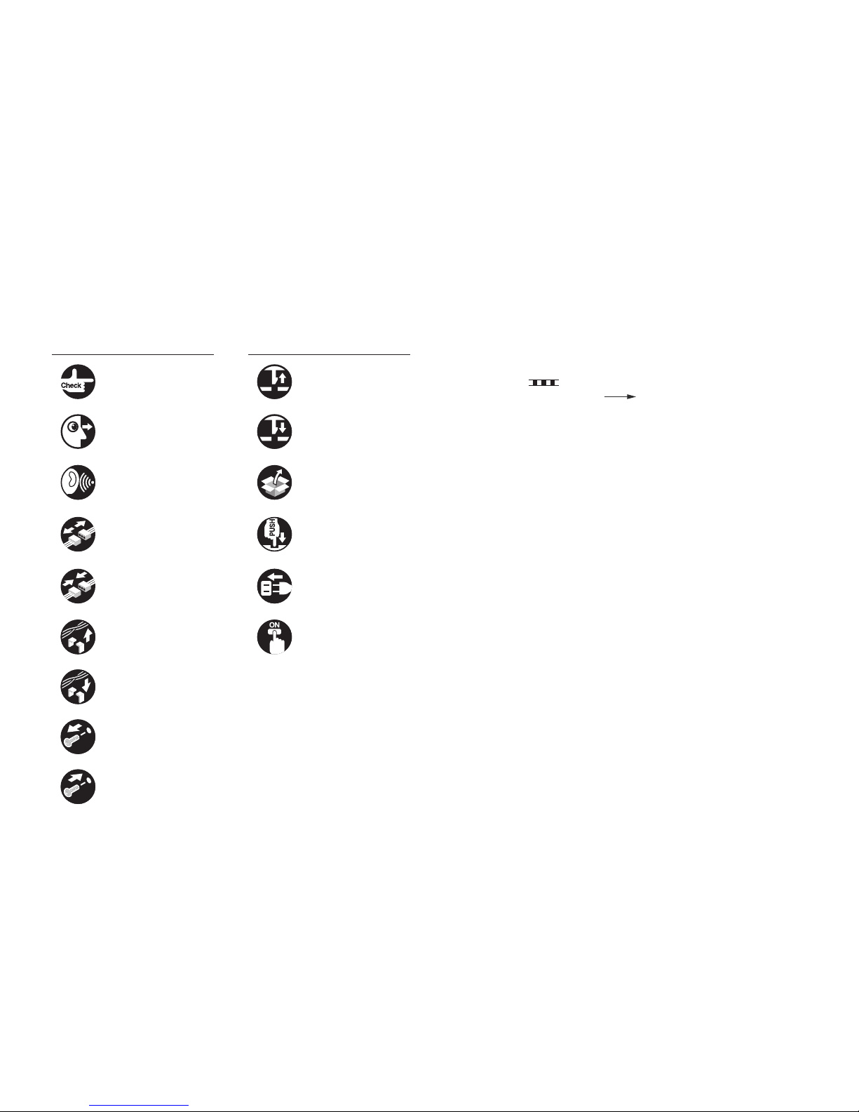
Explanation of Symbols
The following symbols are used throughout this Service Manual.
Symbols Explanation Symbols Explanation
Check. Remove the claw.
Check visually. Insert the claw.
Check the noise. Use the bundled part.
Disconnect the connector. Push the part.
Connect the connector. Plug the power cable.
Remove the cable/wire
from the cable guide or wire
saddle.
Turn on the power.
Set the cable/wire to the
cable guide or wire saddle.
Remove the screw.
Tighten the screw.
The following rules apply throughout this Service Manual:
1. Each chapter contains sections explaining the purpose of specic functions and the
relationship between electrical and mechanical systems with reference to the timing of
operation.
In the diagrams, represents the path of mechanical drive; where a signal name
accompanies the symbol, the arrow indicates the direction of the electric signal.
The expression "turn on the power" means ipping on the power switch, closing the front
door, and closing the delivery unit door, which results in supplying the machine with power.
2. In the digital circuits, '1' is used to indicate that the voltage level of a given signal is "High",
while '0' is used to indicate "Low". (The voltage value, however, differs from circuit to
circuit.) In addition, the asterisk (*) as in "DRMD*" indicates that the DRMD signal goes on
when '0'.
In practically all cases, the internal mechanisms of a microprocessor cannot be checked
in the eld. Therefore, the operations of the microprocessors used in the machines are not
discussed: they are explained in terms of from sensors to the input of the DC controller
PCB and from the output of the DC controller PCB to the loads.
The descriptions in this Service Manual are subject to change without notice for product
improvement or other purposes, and major changes will be communicated in the form of
Service Information bulletins.
All service persons are expected to have a good understanding of the contents of this Service
Manual and all relevant Service Information bulletins and be able to identify and isolate faults
in the machine.

Contents
0
Safety Precautions
CDRH Provisions -------------------------------------------------------------0-6
Laser Safety --------------------------------------------------------------------0-6
About Laser Beams --------------------------------------------------------------- 0-6
Handling Laser Scanner Unit --------------------------------------------------- 0-6
Toner Safety -------------------------------------------------------------------- 0-7
About Toner ------------------------------------------------------------------------- 0-7
Handling Adhered Toner --------------------------------------------------------- 0-7
Notes on Handling Lithium Battery ---------------------------------------0-7
Notes on Assembly/Disassembly -----------------------------------------0-7
1
Product Overview
Product Lineup -----------------------------------------------------------------1-2
Host Machine ----------------------------------------------------------------------- 1-2
L100 / L170 / L174 ------------------------------------------------------------------------- 1-2
L150 -------------------------------------------------------------------------------------------- 1-2
L150 CHN / L150 KOR / L154 ----------------------------------------------------------- 1-2
Product Features --------------------------------------------------------------1-2
Product Features ------------------------------------------------------------------- 1-2
Specications ------------------------------------------------------------------1-3
Product Specications ------------------------------------------------------------ 1-3
ADF Specications ---------------------------------------------------------------- 1-3
FAX Specications ---------------------------------------------------------------- 1-4
Parts Name ---------------------------------------------------------------------1-4
External View ----------------------------------------------------------------------- 1-4
Front side of the machine (L100 / L170 / L174) ------------------------------------- 1-4
Rear side of the machine (L100 / L170 / L174) ------------------------------------- 1-5
Front side of the machine (L150) ------------------------------------------------------- 1-6
Rear side of the machine (L150)-------------------------------------------------------- 1-7
Front side of the machine (L150 CHN / L150 KOR / L154) ---------------------- 1-7
Rear side of the machine (L150 CHN / L150 KOR / L154) ---------------------- 1-8
Cross Sectional View ------------------------------------------------------------- 1-9
Operation Panel (L100 / L170 / L174) ---------------------------------------- 1-9
Operation Panel (L150 / L150 CHN / L150 KOR / L154) ---------------1-10
2
Technical Overview
Basic Conguration -----------------------------------------------------------2-2
Conguration function ------------------------------------------------------------ 2-2
Basic Sequence -------------------------------------------------------------------- 2-2
Basic Sequence of Operation ----------------------------------------------------------- 2-2
Print Sequence ------------------------------------------------------------------------------ 2-3
Power-On Sequence----------------------------------------------------------------------- 2-4
Controller System -------------------------------------------------------------2-5
Main Controller --------------------------------------------------------------------- 2-5
Overview -------------------------------------------------------------------------------------- 2-5
Engine Controller ------------------------------------------------------------------ 2-5
General description ------------------------------------------------------------------------ 2-5
Power Supply ----------------------------------------------------------------------- 2-6
Power Supply -------------------------------------------------------------------------------- 2-6
Protective Functions ----------------------------------------------------------------------- 2-6
Service Tasks ----------------------------------------------------------------------- 2-7
At parts replacement ----------------------------------------------------------------------- 2-7
Maintenance --------------------------------------------------------------------------------- 2-7
Notes on service tasks -------------------------------------------------------------------- 2-7
Original Exposure System --------------------------------------------------2-8
Overview ----------------------------------------------------------------------------- 2-8
Major Components ---------------------------------------------------------------- 2-8
Various Control ------------------------------------------------------------------------------ 2-8
Detecting Jam ---------------------------------------------------------------------- 2-9
Jam Detection Outline --------------------------------------------------------------------- 2-9
Service Tasks ----------------------------------------------------------------------- 2-9
At parts replacement ----------------------------------------------------------------------- 2-9
Maintenance --------------------------------------------------------------------------------- 2-9
Notes on service tasks -------------------------------------------------------------------- 2-9
Laser Exposure System ---------------------------------------------------2-10
Overview ----------------------------------------------------------------------------2-10
Overview -------------------------------------------------------------------------------------2-10
Controlling the Laser Activation Timing -------------------------------------- 2-11

Laser ON/OFF Control -------------------------------------------------------------------2-11
Horizontal Sync Control ------------------------------------------------------------------2-11
Laser Control -----------------------------------------------------------------------2-12
Auto Power Control (APC) --------------------------------------------------------------2-12
Laser Scanner Motor Control --------------------------------------------------2-12
Overview -------------------------------------------------------------------------------------2-12
Scanner Motor Fault Detection --------------------------------------------------------- 2-13
Service Tasks ----------------------------------------------------------------------2-13
At parts replacement ---------------------------------------------------------------------- 2-13
Maintenance --------------------------------------------------------------------------------2-13
Notes on service tasks -------------------------------------------------------------------2-13
Image Formation System ------------------------------------------------- 2-14
Overview/Conguration ---------------------------------------------------------2-14
Overview -------------------------------------------------------------------------------------2-14
Print Process --------------------------------------------------------------------------------2-14
Static Latent Image Formation Block -------------------------------------------------2-15
Development Block------------------------------------------------------------------------2-15
Transfer Block ------------------------------------------------------------------------------2-16
Fixing Block ---------------------------------------------------------------------------------2-16
Drum Cleaning Block ---------------------------------------------------------------------2-16
High-Voltage Control ------------------------------------------------------------- 2-17
Overview -------------------------------------------------------------------------------------2-17
Generating Primary Charging Bias ---------------------------------------------------- 2-17
Generating Developing Bias ------------------------------------------------------------2-17
Generating Transfer Bias ----------------------------------------------------------------2-17
Toner Cartridge --------------------------------------------------------------------2-18
Toner Level Detection --------------------------------------------------------------------2-18
Specication of Toner level display ----------------------------------------------------2-18
Operation when toner level is Low/Nearly Out -------------------------------------2-18
Toner Cartridge Absence/Presence Detection -------------------------------------2-19
Service Tasks ----------------------------------------------------------------------2-19
At parts replacement ---------------------------------------------------------------------- 2-19
Maintenance --------------------------------------------------------------------------------2-19
Notes on service tasks -------------------------------------------------------------------2-19
Fixing System ----------------------------------------------------------------2-20
Overview/Conguration ---------------------------------------------------------2-20
Overview -------------------------------------------------------------------------------------2-20
Main Parts of Fixing assembly ---------------------------------------------------------2-20
Various Control Mechanisms --------------------------------------------------2-21
Fixing Temperature Control -------------------------------------------------------------2-21
Protective Functions ----------------------------------------------------------------------2-21
Other Functions -------------------------------------------------------------------2-23
Throughput Down Control ---------------------------------------------------------------2-23
Service Tasks ----------------------------------------------------------------------2-24
At parts replacement ---------------------------------------------------------------------- 2-24
Maintenance --------------------------------------------------------------------------------2-24
Notes on service tasks -------------------------------------------------------------------2-24
Pickup Feed System ------------------------------------------------------- 2-25
Overview ----------------------------------------------------------------------------2-25
Overview -------------------------------------------------------------------------------------2-25
Detecting Jams --------------------------------------------------------------------2-26
Jam Detection Outline --------------------------------------------------------------------2-26
Delay Jam -----------------------------------------------------------------------------------2-26
Stationary Jam -----------------------------------------------------------------------------2-28
Other Jams ----------------------------------------------------------------------------------2-28
Service Tasks ----------------------------------------------------------------------2-29
At parts replacement ---------------------------------------------------------------------- 2-29
Maintenance --------------------------------------------------------------------------------2-29
Notes on service tasks -------------------------------------------------------------------2-29
3
Periodical Services
Periodically Replaced Parts ------------------------------------------------3-2
Periodically Replaced Parts ----------------------------------------------------- 3-2
Consumables ------------------------------------------------------------------3-2
Consumables ----------------------------------------------------------------------- 3-2
Periodical Service -------------------------------------------------------------3-2
Scheduled Servicing -------------------------------------------------------------- 3-2
Cleaning -------------------------------------------------------------------------3-2
4
Disassembly/Assembly
PREFACE -----------------------------------------------------------------------4-2
Outline -------------------------------------------------------------------------------- 4-2
List Of Parts --------------------------------------------------------------------4-3
External View ----------------------------------------------------------------------- 4-3
Front Side (L100/L170/L174/L250/L150 CHN/L150 KOR/L154) --------------- 4-3

Rear Side (L100/L170/L174/L250/L150 CHN/L150 KOR/L154) ---------------- 4-4
Front Side (L150 EUR/L150 AUS)------------------------------------------------------ 4-4
Rear Side (L150 EUR/L150 AUS) ------------------------------------------------------ 4-5
Front Side (L150 CHN/L150 KOR/L154) --------------------------------------------- 4-6
Rear Side (L150 CHN/L150 KOR/L154) ---------------------------------------------- 4-7
List of Main Unit -------------------------------------------------------------------- 4-7
ADF Unit (L100/L170/L174/L250/L150 CHN/L150 KOR/L154) ----------------- 4-7
ADF Unit (L150 EUR/L150 AUS) ------------------------------------------------------- 4-8
ADF Unit (L150 CHN/L150 KOR/L154) ----------------------------------------------- 4-8
Printer Unit ----------------------------------------------------------------------------------- 4-9
Electrical Components ------------------------------------------------------------ 4-9
ADF Unit (L100/L170/L174/L250/L150 CHN/L150 KOR/L154) ----------------- 4-9
ADF Unit (L150 EUR/L150 AUS) ------------------------------------------------------4-10
Motor ------------------------------------------------------------------------------------------ 4-10
Solenoid -------------------------------------------------------------------------------------- 4-11
Sensor ----------------------------------------------------------------------------------------4-11
Switch/Speaker -----------------------------------------------------------------------------4-12
Heater/Thermistor/Thermoswitch/ -----------------------------------------------------4-12
PCB -------------------------------------------------------------------------------------------4-13
List of Connectors ----------------------------------------------------------- 4-14
ADF Unit ----------------------------------------------------------------------------4-14
(L100/L170/L174/L250/L150 CHN/L150 KOR/L154) -----------------------------4-14
(L150 EUR/L150 AUS) -------------------------------------------------------------------4-15
Printer Unit --------------------------------------------------------------------------4-16
External Cover ---------------------------------------------------------------4-18
Layout Drawing -------------------------------------------------------------------- 4-18
Front Side (L100/L170/L174/L250/L150 CHN/L150 KOR/L154) --------------4-18
Rear Side (L100/L170/L174/L250/L150 CHN/L150 KOR/L154) ---------------4-19
Front Side (L150 EUR/L150 AUS)-----------------------------------------------------4-19
Rear Side (L150 EUR/L150 AUS) -----------------------------------------------------4-20
Front Side (L150 CHN/L150 KOR/L154) --------------------------------------------4-21
Rear Side (L150 CHN/L150 KOR/L154) ---------------------------------------------4-22
Removing the ADF Left Cover -------------------------------------------------4-23
Procedure ------------------------------------------------------------------------------------4-23
Removing the ADF Right Cover -----------------------------------------------4-23
Procedure ------------------------------------------------------------------------------------4-23
Removing the Handset Base Unit
(L100/L170/L174/L250/L150 CHN/L150 KOR/L154) --------------------4-24
Preparation ----------------------------------------------------------------------------------4-24
Procedure ------------------------------------------------------------------------------------4-24
Removing the ADF Left Upper Cover
(L150 EUR/L150 AUS) ----------------------------------------------------------4-26
Procedure ------------------------------------------------------------------------------------4-26
Removing the Left Cover -------------------------------------------------------4-27
Procedure ------------------------------------------------------------------------------------4-27
Removing the Right Cover -----------------------------------------------------4-28
Procedure ------------------------------------------------------------------------------------4-28
Removing the Front Cover Unit -----------------------------------------------4-29
Preparation ----------------------------------------------------------------------------------4-29
Procedure ------------------------------------------------------------------------------------4-29
Removing the Rear Cover ------------------------------------------------------4-29
Preparation ----------------------------------------------------------------------------------4-29
Procedure ------------------------------------------------------------------------------------4-29
Removing the Upper Cover ----------------------------------------------------4-30
Preparation ----------------------------------------------------------------------------------4-30
Procedure ------------------------------------------------------------------------------------4-30
Controller System -----------------------------------------------------------4-33
Layout Drawing -------------------------------------------------------------------- 4-33
Removing the Operation Panel Unit -----------------------------------------4-34
Procedure ------------------------------------------------------------------------------------4-34
Removing the Drive Belt --------------------------------------------------------4-34
Preparation ----------------------------------------------------------------------------------4-34
Procedure ------------------------------------------------------------------------------------4-34
Removing the Main Motor ------------------------------------------------------4-36
Preparation ----------------------------------------------------------------------------------4-36
Procedure ------------------------------------------------------------------------------------4-36
Removing the Main Controller PCB ------------------------------------------4-39
Before Replacing the Main Controller PCB -----------------------------------------4-39
Preparation ----------------------------------------------------------------------------------4-39
Procedure ------------------------------------------------------------------------------------4-39
After Replacing the Main Controller PCB -------------------------------------------- 4-40
Removing the Engine Controller PCB ---------------------------------------4-40
Preparation ----------------------------------------------------------------------------------4-40
Procedure ------------------------------------------------------------------------------------4-40
Removing the Communication PCB Unit -----------------------------------4-44

Preparation ----------------------------------------------------------------------------------4-44
Procedure ------------------------------------------------------------------------------------4-44
Removing the NCU PCB -------------------------------------------------------- 4-45
Preparation ----------------------------------------------------------------------------------4-45
Procedure ------------------------------------------------------------------------------------4-45
Removing the Paper Leading Edge Sensor--------------------------------4-45
Preparation ----------------------------------------------------------------------------------4-45
Procedure ------------------------------------------------------------------------------------4-45
Removing the Fixing Delivery/Paper Width Sensor PCB ---------------4-47
Preparation ----------------------------------------------------------------------------------4-47
Procedure ------------------------------------------------------------------------------------4-47
Removing the Toner Sensor ---------------------------------------------------4-49
Preparation ----------------------------------------------------------------------------------4-49
Procedure ------------------------------------------------------------------------------------4-49
Removing the Speaker ----------------------------------------------------------4-51
Preparation ----------------------------------------------------------------------------------4-51
Procedure ------------------------------------------------------------------------------------4-51
Original Exposure System ------------------------------------------------ 4-52
Layout Drawing -------------------------------------------------------------------- 4-52
(L100/L170/L174/L250/L150 CHN/L150 KOR/L154) -----------------------------4-52
(L150 EUR/L150 AUS) -------------------------------------------------------------------4-53
Removing the ADF Unit ---------------------------------------------------------4-54
Preparation ----------------------------------------------------------------------------------4-54
Procedure ------------------------------------------------------------------------------------4-54
Removing the ADF Upper Unit
(L100/L170/L174/L250/L150 CHN/L150 KOR/L154) --------------------4-56
Preparation ----------------------------------------------------------------------------------4-56
Procedure ------------------------------------------------------------------------------------4-56
Removing the ADF Upper Unit (L150 EUR/L150 AUS) -----------------4-58
Preparation ----------------------------------------------------------------------------------4-58
Procedure ------------------------------------------------------------------------------------4-58
Removing the Document Feed Tray -----------------------------------------4-61
Preparation ----------------------------------------------------------------------------------4-61
Procedure ------------------------------------------------------------------------------------4-61
Removing the ADF Upper Unit and ADF Lower Unit
(L100/L170/L174/L250/L150 CHN/L150 KOR/L154) --------------------4-62
Preparation ----------------------------------------------------------------------------------4-62
Procedure ------------------------------------------------------------------------------------4-62
Removing the ADF Upper Unit and ADF Lower Unit
(L150 EUR/L150 AUS) ----------------------------------------------------------4-65
Preparation ----------------------------------------------------------------------------------4-65
Procedure ------------------------------------------------------------------------------------4-65
Removing the CIS Unit ----------------------------------------------------------4-68
Preparation ----------------------------------------------------------------------------------4-68
Procedure ------------------------------------------------------------------------------------4-68
Removing the White Plate Retainer ------------------------------------------ 4-69
Preparation ----------------------------------------------------------------------------------4-69
Procedure ------------------------------------------------------------------------------------4-69
Removing the ADF Pickup Roller --------------------------------------------- 4-70
Preparation ----------------------------------------------------------------------------------4-70
Procedure ------------------------------------------------------------------------------------4-70
Removing the ADF Feed Roller -----------------------------------------------4-72
Preparation ----------------------------------------------------------------------------------4-72
Procedure ------------------------------------------------------------------------------------4-72
Removing the ADF Separation Pad ------------------------------------------ 4-74
Procedure ------------------------------------------------------------------------------------4-74
Removing the ADF Delivery Roller -------------------------------------------4-75
Preparation ----------------------------------------------------------------------------------4-75
Procedure ------------------------------------------------------------------------------------4-75
Laser Exposure System ---------------------------------------------------4-77
Layout Drawing -------------------------------------------------------------------- 4-77
Removing the Laser Scanner Unit --------------------------------------------4-77
Preparation ----------------------------------------------------------------------------------4-77
Procedure ------------------------------------------------------------------------------------4-77
Image Formation System ------------------------------------------------- 4-79
Layout Drawing -------------------------------------------------------------------- 4-79
Removing the Transfer Roller --------------------------------------------------4-79
Procedure ------------------------------------------------------------------------------------4-79
Fixing System ----------------------------------------------------------------4-81
Layout Drawing -------------------------------------------------------------------- 4-81
Removing the Fixing Assembly ------------------------------------------------4-81
Preparation ----------------------------------------------------------------------------------4-81
Procedure ------------------------------------------------------------------------------------4-81
Pickup Feed System ------------------------------------------------------- 4-86
Layout Drawing -------------------------------------------------------------------- 4-86

Removing the Pickup Unit ------------------------------------------------------4-86
Preparation ----------------------------------------------------------------------------------4-86
Procedure ------------------------------------------------------------------------------------4-86
Removing the Pickup Roller ----------------------------------------------------4-90
Preparation ----------------------------------------------------------------------------------4-90
Removing the Pickup Solenoid ------------------------------------------------ 4-91
Preparation ----------------------------------------------------------------------------------4-91
Procedure ------------------------------------------------------------------------------------4-91
Removing the Separation Pad -------------------------------------------------4-93
Preparation ----------------------------------------------------------------------------------4-93
5
Adjustment
Electrical Adjustment ---------------------------------------------------------5-2
Electric part-related adjustment ------------------------------------------------ 5-2
When Replacing the Main Controller PCB ------------------------------------------- 5-2
After Replacing the Main Controller PCB --------------------------------------------- 5-2
6
Trouble Shooting
Test Print ------------------------------------------------------------------------6-2
Test Print Function ----------------------------------------------------------------- 6-2
Trouble Shooting Items ------------------------------------------------------6-3
Image Faults ------------------------------------------------------------------------ 6-3
Smudged/Streaked ------------------------------------------------------------------------- 6-3
Repetitive image defects ruler ----------------------------------------------------------- 6-4
Mechanical Adjustment ------------------------------------------------------6-4
Conrming Nip Width ------------------------------------------------------------- 6-4
Version Upgrade --------------------------------------------------------------6-5
Overview ----------------------------------------------------------------------------- 6-5
Preparation -------------------------------------------------------------------------- 6-5
System Requirements --------------------------------------------------------------------- 6-5
Preparation ----------------------------------------------------------------------------------- 6-5
Downloading System Software ------------------------------------------------- 6-6
Log Collector -------------------------------------------------------------------6-8
Overview ----------------------------------------------------------------------------- 6-8
Scope of Application ----------------------------------------------------------------------- 6-8
Operation Procedure----------------------------------------------------------------------- 6-8
Troubleshooting ----------------------------------------------------------------------------- 6-9
7
Error Codes
Overview ------------------------------------------------------------------------7-2
Error Codes ---------------------------------------------------------------------7-3
FAX Error Code ----------------------------------------------------------------7-4
Error Code Overview -------------------------------------------------------------- 7-4
Overview -------------------------------------------------------------------------------------- 7-4
User Error Code -------------------------------------------------------------------- 7-4
Error Code ------------------------------------------------------------------------------------ 7-4
Service Error Code ---------------------------------------------------------------- 7-4
Error Code ------------------------------------------------------------------------------------ 7-4
8
Service Mode
Overview ------------------------------------------------------------------------8-2
Entering Service Mode. ---------------------------------------------------------- 8-2
Exiting Service Mode ------------------------------------------------------------- 8-2
Service Mode Menu --------------------------------------------------------------- 8-2
Screen ow of Service mode ------------------------------------------------------------ 8-2
COPIER -------------------------------------------------------------------------8-3
DISPLAY ----------------------------------------------------------------------------- 8-3
VERSION ------------------------------------------------------------------------------------- 8-3
CCD -------------------------------------------------------------------------------------------- 8-3
I/O -------------------------------------------------------------------------------------- 8-3
R-CON ----------------------------------------------------------------------------------------- 8-3
ADJUST ------------------------------------------------------------------------------ 8-3
CCD -------------------------------------------------------------------------------------------- 8-3
FUNCTION -------------------------------------------------------------------------- 8-4
CLEAR ---------------------------------------------------------------------------------------- 8-4
MISC-R ---------------------------------------------------------------------------------------- 8-4
MISC-P ---------------------------------------------------------------------------------------- 8-4
SYSTEM -------------------------------------------------------------------------------------- 8-4
PARAM ---------------------------------------------------------------------------------------- 8-4
SPLMAN -------------------------------------------------------------------------------------- 8-5
OPTION ------------------------------------------------------------------------------ 8-5
BODY ------------------------------------------------------------------------------------------ 8-5
COUNTER --------------------------------------------------------------------------- 8-6
TOTAL ----------------------------------------------------------------------------------------- 8-6

PICK-UP -------------------------------------------------------------------------------------- 8-6
FEEDER -------------------------------------------------------------------------------------- 8-7
JAM -------------------------------------------------------------------------------------------- 8-7
FEEDER -------------------------------------------------------------------------8-8
ADJUST ------------------------------------------------------------------------------ 8-8
FUNCTION -------------------------------------------------------------------------- 8-8
FAX -------------------------------------------------------------------------------8-9
List of SSSW ------------------------------------------------------------------------ 8-9
List of MENU -----------------------------------------------------------------------8-10
List of NUM -------------------------------------------------------------------------8-11
Setting of NCU Parameters ----------------------------------------------------8-11
TONE/PULSE ------------------------------------------------------------------------------ 8-11
2ND DTN ------------------------------------------------------------------------------------8-12
BUSTONE0 ---------------------------------------------------------------------------------8-12
BUSTONE1 ---------------------------------------------------------------------------------8-12
REORDRTN --------------------------------------------------------------------------------8-13
MULTI -----------------------------------------------------------------------------------------8-13
AUTO RX ------------------------------------------------------------------------------------8-13
CNGDTCT ----------------------------------------------------------------------------------- 8-13
SPECIALB ----------------------------------------------------------------------------------- 8-14
SPECIALN -----------------------------------------------------------------------------------8-14
RKEY -----------------------------------------------------------------------------------------8-14
PBXDIALT -----------------------------------------------------------------------------------8-14
PBXBUSYT ---------------------------------------------------------------------------------8-14
TESTMODE ------------------------------------------------------------------ 8-15
SYSTEM ----------------------------------------------------------------------------8-15
DRAM -----------------------------------------------------------------------------------------8-15
SPEAKER -----------------------------------------------------------------------------------8-15
SCAN --------------------------------------------------------------------------------8-15
ADJUST -------------------------------------------------------------------------------------- 8-15
SENSOR ------------------------------------------------------------------------------------- 8-15
ADFTEST ------------------------------------------------------------------------------------ 8-15
FAX ----------------------------------------------------------------------------------- 8-16
MODEM --------------------------------------------------------------------------------------8-16
FACULTY ------------------------------------------------------------------------------------8-16
PANEL -------------------------------------------------------------------------------8-16
9
Appendix
Service Tools ------------------------------------------------------------------- 9-2
Solvent/Oil List -----------------------------------------------------------------9-3
General Circuit Diagram ------------------------------------------------------ IV
General Circuit Diagram ----------------------------------------------------------- IV
Signal Input/Output List ------------------------------------------------------9-5
General Timing Chart --------------------------------------------------------9-6
Backup Data --------------------------------------------------------------------9-7

■CDRH Provisions
■Laser Safety
■Toner Safety
■Notes on Handling
Lithium Battery
■Notes on Assembly/
Disassembly
Safety Precautions
L100/L150/L154/L170/L174
Series
0-11
0-11
CDRH Provisions
Food and Drug CDRH (Center for Devices and Radiological Health) under FDA (Food and
Drug Administration) enforced provisions of the section for laser and laser products on August
2, 1976. These provisions are applicable to all laser products manufactured or assembled
after August 1, 1976 and allow only products certied their compliance with the provisions
to market in the US. Each product shall have afxed the applicable label as shown below to
follow the labeling requirements prescribed in CDRH provisions.
Note that the wording included in labels is different depending on laser product
classications.
F-0-1
Laser Safety
About Laser Beams
Laser radiation may be hazardous to human. The laser scanner unit mounted in this device is
sealed in the protective housing and the external cover to prevent laser beams from leaking
to the environment. As long as the device is operated under normal conditions, users are
safely guarded from laser leaks.
This product is certicated as a Class 1 laser product under IEC60825-1:2007.
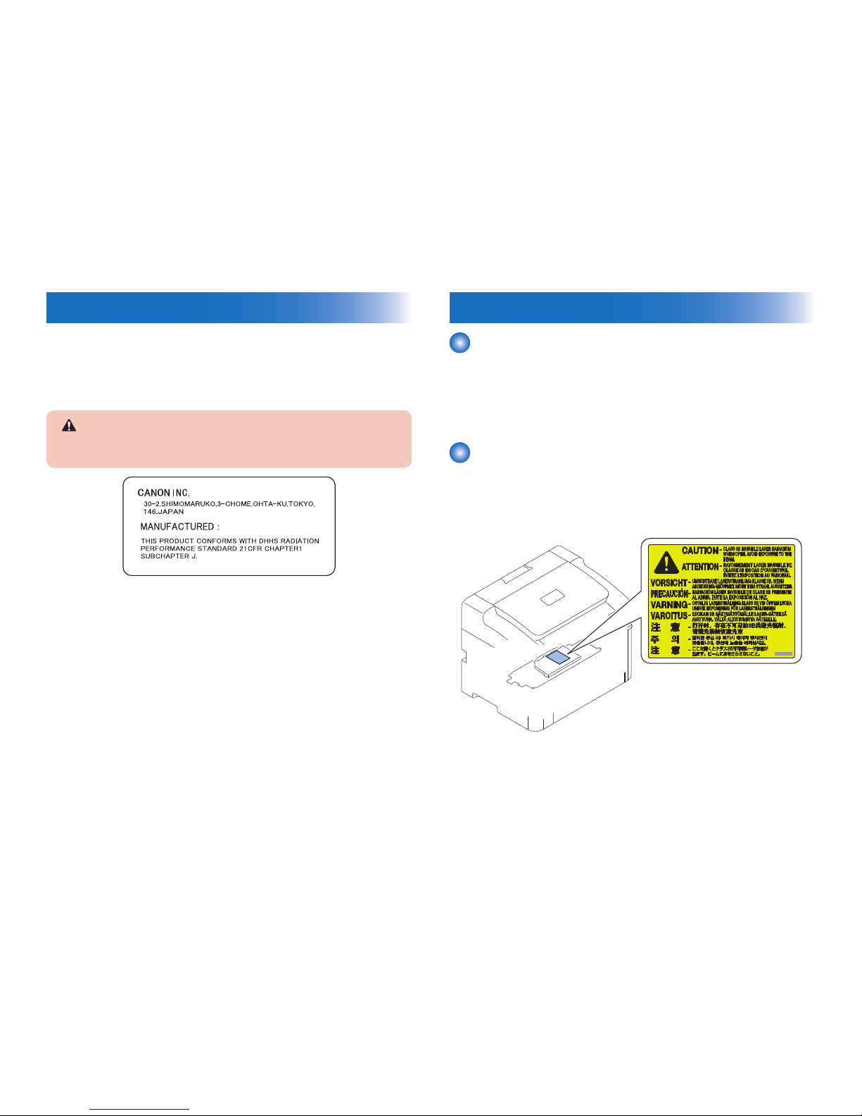
Handling Laser Scanner Unit
Before providing service works for the laser scanner unit and its peripherals, ensure to turn
off the power of the device.
Any cover with potential dangers of laser beam reection has afxed the caution label at the
position shown in the gure below.
F-0-2

0-12
0-12
Toner Safety
About Toner
Toner is a non-toxic material composed of plastic, iron, small amount of pigment, etc.
Never throw toner in ames to avoid explosion.
Handling Adhered Toner
• Use dry tissue paper to wipe off toner adhered to skin or clothes and wash in water.
• Never use warm water for cleaning up toner to prevent toner particles from being able to
soak into bers permanently.
• Toner particles are reactive with vinyl polymers. Avoid contacting these materials.
F-0-3
Notes on Handling Lithium Battery
CAUTION:
The battery installed in this machine is xed and cannot be replaced.
When disposing of an old battery, remove it from the PCB and follow the
local regulation.
The following warnings are given to comply with Safety Principles (EN60950).
Achtung:
Wenn mit dem falschen Typ ausgewechselt, besteht Explosionsgefahr.
Gebrauchte Batterien gemäß der Anleitung beseitigen.
Notes on Assembly/Disassembly
Follow the items below to assemble/disassemble the device.
1. Disconnect the power plug to avoid any potential dangers during assembling/disassembling
works.
2. If not specially instructed, reverse the order of disassembly to reinstall.
3. Ensure to use the right screw type (length, diameter, etc.) at the right position when
assembling.
4. To keep electric conduction, binding screws with washers are used to attach the grounding
wire and the varistor. Ensure to use the right screw type when assembling.
5. Unless it is specially needed, do not operate the device with some parts removed.
6. Never remove the paint-locked screws when disassembling.

1
1
Product Overview
Product Overview
■Product Lineup
■Product Features
■Specications
■Parts Name

1
1
1-2
1-2
Product Overview > Product Features > Product Features
Product Overview > Product Features > Product Features
Product Lineup
Host Machine
Model name L100 / L170 / L174 L150
L150 CHN / L150 KOR
/ L154
Conguration
3in1 single-sided ADF 3in1 single-sided ADF 3in1 single-sided ADF
Design
SADF
○ ○ ○
Engine 1-sided
Yes Yes Yes
LAN Port
- - -
FAX
○ ○ ○
Options
■L100 / L170 / L174
None
■L150
Handset
■L150 CHN / L150 KOR / L154
None
T-1-1
Product Features
Product Features
1. Compact/high-speed printer
This machine is a high-speed B&W printer with a compact body design and the print speed
of 19 ppm (LTR).
2. Reduced standby time and low energy consumption
This machine uses the on-demand xing method in which power is supplied to the heater
only at printing.
This realized the reduction of standby time and low energy consumption during standby.
3. Reduced operation noise and stabilized image quality
This machine uses the belt drive method for the Main Motor's drive transmission.
The operation noise is reduced and image quality is stabilized compared to the
conventional gear drive method (see NOTE).
4. Improved user operability
User operability is improved by concentrating the maintenance processes (jam removal
and cartridge replacement) in a single location at the Upper Cover.
Note:
By changing the drive method from gear to belt, uneven cycle of the Photosensitive
Drum is reduced. This makes it possible to realize stabilized image quality.
1
1
1-3
1-3
Product Overview > Specications > ADF Specications
Product Overview > Specications > ADF Specications
Specications
Product Specications
Copyboard Stream reading
Machine installation method Desktop
Light source LED
Image reading method CIS
Photosensitive medium OPC Drum (φ24 mm )
Exposure method Laser beam (semiconductor laser)
Charging method Roller charging method
Developing method Jumping development method
Transfer method Roller transfer method
Separation method Curvature separation
Paper feed method Pickup Tray : Pad separation method
Multi-purpose Tray : None
Delivery method Face-down
Drum cleaning method Blade cleaning
Fixing method On-demand method
Toner supplying method Toner Cartridge replacement
Toner level detection Yes
Document type Sheet
Maximum document size 216 mm×356 mm
Magnication ratio 100 % magnication
50 to 200 % (in increments of 1 %)
Resolution at reading 600 dpi × 600 dpi
600 dpi x 196 dpi/600 dpi x 392 dpi (At the time of FAX)
Print resolution 600 dpi x 400 dpi/600 dpi x 600 dpi *
Warm-up time Minimum (without Toner Cartridge replacement): 14 sec. or less /
When a new Toner Cartridge is installed: 42 sec. or less
First print time 7.7 sec. or less (LTR, default setting)
First copy time 21.3 sec. or less (LTR, default setting)
Print speed 18 ppm mode setting:19 ppm (LTR)
12 ppm mode setting: 12.4ppm(LTR)
Copy speed 12.4 ppm (LTR) **
Paper size Fixed size:
A4, B5, A5, LGL, LTR, Statement, Executive, Ofcio, B-ofcio,
M-ofcio, Government-Letter, Government-Legal, Foolscap,
A-foolscap, Envelope COM10, Envelope C5, Envelope B5,
Envelope DL
Custom size:
Width: 76.2 to 216 mm, Length: 127 to 356 mm
Paper types Plain paper (60 to 89 g/m2), Heavy paper (90 to 163 g/m2), Rough
paper (60 to 163 g/m2), Transparency, Label, Envelope
Pickup Tray capacity Approx. 150 sheets (plain paper: 60 to 80 g/m2)
Delivery Tray capacity Approx. 60 sheets (plain paper: 60 to 80 g/m2)
Environment temperature range 10 to 30 degrees Centigrade
Environment humidity range 20 to 80 %
Duplex method None
Host Interface Standard: USB/Hi-speed USB, Options: None
Hard disk capacity Standard: None, Options: None
Memory capacity Standard: 64 MB, Options: None
Power supply AC110 to 127 V +/- 10 %, ( 50,60 Hz +/- 2 Hz)
AC220 to 240 V +/- 10 %, ( 50,60 Hz +/- 2 Hz)
Maximum power consumption 900 W or less (120 V), 1020 W or less (230 V)
Power consumption 410 W or less (120 V), 400 W or less (230 V)
External dimensions (W x D xH) 372 × 276 × 254 mm
Weight L100 / L170 / L174
Approx. 8.24 kg (including Toner Cartridge)
L150
Approx. 8.0 kg (including Toner Cartridge)
L150 CHN / L150 KOR / L154
Approx. 8.2 kg (including Toner Cartridge)
*: Resolution switching
With this machine, 2 types of resolution can be switched by setting "Copy Type" on the
printer driver.
Speed priority (at the time of shipment): 600 dpi × 400 dpi
Resolution priority: 600 dpi × 600 dpi
**: Copy : 600 dpi x 600 dpi only
ADF Specications
Document Exposure LED
Document Scan document stream reading by xed contact image sensor (CIS)
Scanning Resolution 600 dpi (horizontal scanner) X 600 dpi (vertical scanner)
Number Of Gradations 256
Magnication 50 % to 200 % (1 % increment)
horizontal : image processing by Main Controller PCB
vertical : image processing by Main Controller PCB
Lens CIS/Color
CIS Unit number of lines: 1 line
number of pixels: 5148 pixels as total pixels (5107 pixels as
effective pixels)
maximum document scanning width: 216 mm
Documentdrive control CIS is xed, and does not execute drive control.
Document is moved by the DF Motor, which is controlled by the
Main Controller PCB.
Document size detection None
T-1-2
T-1-3
1
1
1-4
1-4
Product Overview > Parts Name > External View > Front side of the machine (L100 / L170 / L174)
Product Overview > Parts Name > External View > Front side of the machine (L100 / L170 / L174)
FAX Specications
Suitable Line Public Switched Telephone Network (PSTN)*1
Communication Protocol Super G3
Modem speed 33.6 Kbps
Data compression method MH, MR, MMR
Transmission Speed Approx. 3 sec. per page*2
(ECM-MMR, sent from memory at 33.6 Kbps)
Send/receive memory L100 / L150 / L170 / L174
Transmission: 10 jobs / Reception: 30 jobs
(Total number of sent/received pages: approx. 512 pages *2)
L150 CHN / L150 KOR / L154
Transmission: 10 jobs / Reception: 30 jobs
(Total number of sent/received pages: approx. 346 pages *2)
Fax Resorution (Normal) : 200dpi x 100 dpi
(Fine) : 200dpi x 200 dpi
(Photo) : 200dpi x 200 dpi
(Super ne) : 200dpi x 400 dpi
Dial method L100 / L170 / L174
One-touch dial : 30
L150 / L150 CHN / L150 KOR / L154
One-touch dial : 15
Abbreviation dial : 100
Group dial : 129
Address book dial
Normal dial : entry by numeric keypad
Auto redial
Manual redial
Concurrent transmission : 140
Reception method Auto reception
Remote reception by a telephone (initial setting ID: 25)
Report output TX Report
Communication Management Report
(to be output automatically for every 40 communications)
RX Report
Number Display Not supported
*1The Public Switched Telephone Network (PSTN) currently supports 28.8 Kbps modem
speed or lower. Note that speeds can vary depending on the telephone line conditions.
*2Based on ITU-T (ITU Telecommunication Standardization Sector) Standard Chart No. 1,
MMR standard mode.
T-1-4
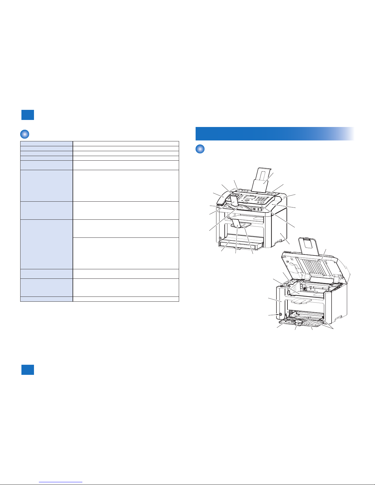
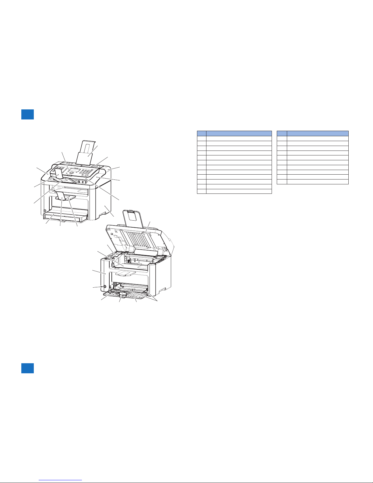
Parts Name
External View
■Front side of the machine (L100 / L170 / L174)
[6]
[7]
[9]
[8]
[4]
[5]
[3]
[2]
[1]
[12]
[11]
[10]
[13]
[14]
[15]
[17]
[18]
[19]
[20]
[21]
[22]
[23]
[24]
[16]
F-1-1
1
1
1-5
1-5
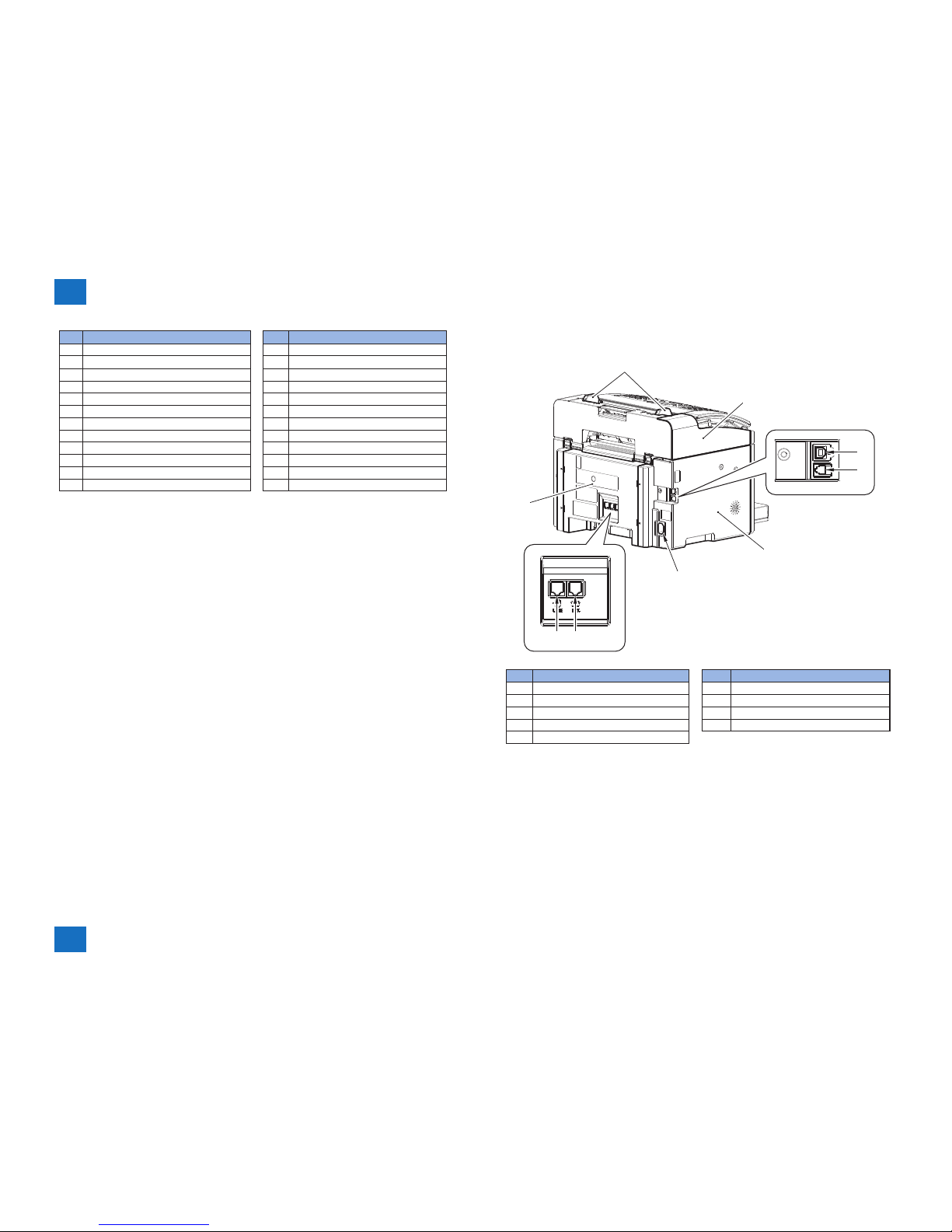
Product Overview > Parts Name > External View > Rear side of the machine (L100 / L170 / L174)
Product Overview > Parts Name > External View > Rear side of the machine (L100 / L170 / L174)
No. Name No. Name
[1] Document Pickup Tray [13] Handset
[2] Document Feed Tray [14] Onetouch Cover
[3] ADF Right Cover [15] Operation Panel Unit
[4] ADF Upper Cover [16] ADF Lower Cover
[5] ADF Upper Unit Lower Cover [17] Pickup Tray Paper Guides
[6] Right Cover [18] Pickup Tray
[7] Delivery Auxiliary Tray [19] Pickup Tray Trailing Edge Paper
[8] Delivery Stopper [20] Small Size Paper Guides
[9] Dust Cover [21] Power Button
[10] Document Return Tray [22] Front Cover Unit
[11] Document Stopper [23] Delivery Tray
[12] Handset Base [24] Upper Cover
■Rear side of the machine (L100 / L170 / L174)
[1]
[2]
[5]
[6]
[7][8]
[9]
[3]
[4]
No. Name No. Name
[1] Document Guides [6] Power Supply Socket
[2] ADF Left Cover [7] External Device Jack
[3] USB Port [8] Telephon Line Jack
[4] Handset Jack [9] Rear Cover
[5] Left Cover
F-1-2
1
1
1-6
1-6
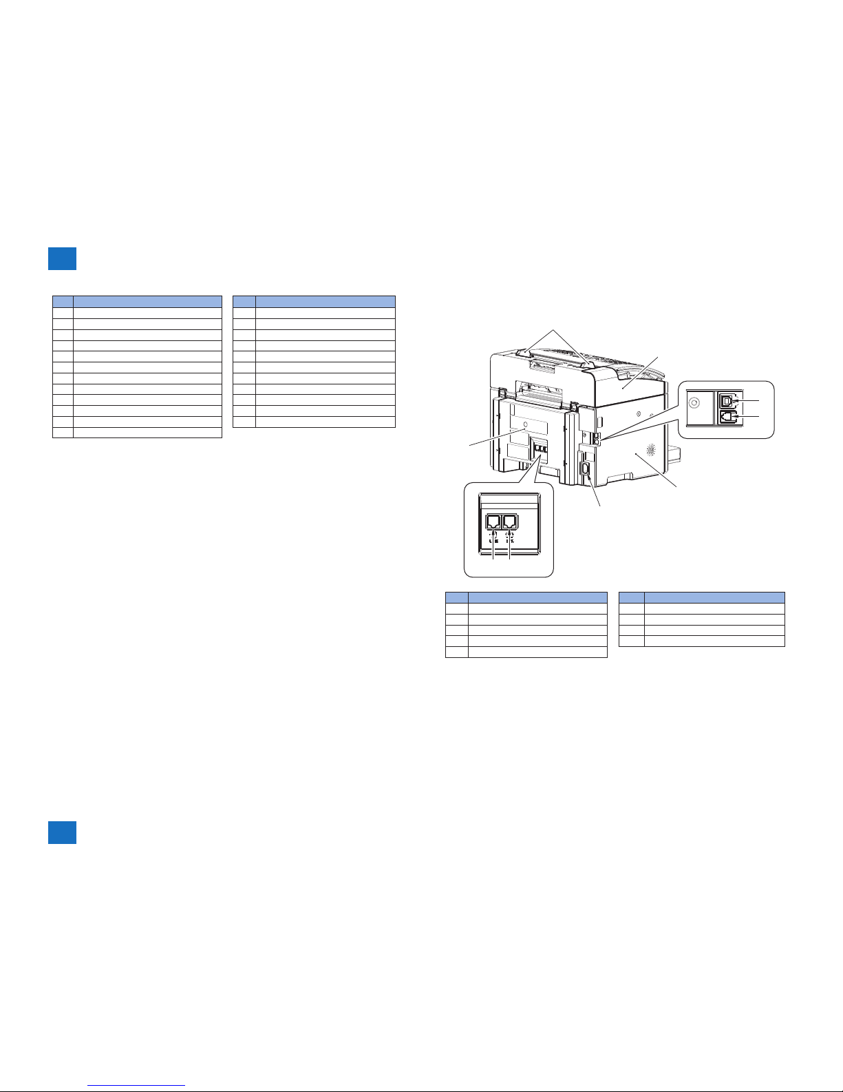
Product Overview > Parts Name > External View > Front side of the machine (L150)
Product Overview > Parts Name > External View > Front side of the machine (L150)
■Front side of the machine (L150)
[7]
[9]
[8]
[12]
[13]
[15]
[16]
[17]
[18]
[19]
[20]
[21]
[22]
[6]
[4]
[5]
[3]
[2]
[1]
[14]
[11]
[10]
F-1-3
No. Name No. Name
[1] Document Pickup Tray [13] Operation Panel Unit
[2] Document Feed Tray [14] ADF Lower Cover
[3] ADF Right Cover [15] Pickup Tray Paper Guides
[4] ADF Upper Cover [16] Pickup Tray
[5] ADF Upper Unit Lower Cover [17] Pickup Tray Trailing Edge Paper
[6] Right Cover [18] Small Size Paper Guides
[7] Delivery Auxiliary Tray [19] Power Button
[8] Delivery Stopper [20] Front Cover Unit
[9] Dust Cover [21] Delivery Tray
[10] Document Return Tray [22] Upper Cover
[11] Document Stopper
[12] ADF Left Upper Cover
1
1
1-7
1-7
Product Overview > Parts Name > External View > Front side of the machine (L150 CHN / L150 KOR / L154)
Product Overview > Parts Name > External View > Front side of the machine (L150 CHN / L150 KOR / L154)
■Rear side of the machine (L150)
[1]
[2]
[3]
[4]
[5]
[7] [6][8]
[9]
No. Name No. Name
[1] Document Guides [6] Handset Jack
[2] ADF Left Cover [7] External Device Jack
[3] USB Port [8] Telephon Line Jack
[4] Left Cover [9] Rear Cover
[5] Power Supply Socket
F-1-4
■Front side of the machine (L150 CHN / L150 KOR / L154)
[7]
[9]
[8]
[12]
[11]
[10]
[13]
[14]
[16]
[17]
[18]
[19]
[20]
[21]
[22]
[23]
[6]
[4]
[5]
[3]
[2]
[1]
[15]
F-1-5
1
1
1-8
1-8
Product Overview > Parts Name > External View > Rear side of the machine (L150 CHN / L150 KOR / L154)
Product Overview > Parts Name > External View > Rear side of the machine (L150 CHN / L150 KOR / L154)
No. Name No. Name
[1] Document Pickup Tray [13] Handset
[2] Document Feed Tray [14] Operation Panel Unit
[3] ADF Right Cover [15] ADF Lower Cover
[4] ADF Upper Cover [16] Pickup Tray Paper Guides
[5] ADF Upper Unit Lower Cover [17] Pickup Tray
[6] Right Cover [18] Pickup Tray Trailing Edge Paper
[7] Delivery Auxiliary Tray [19] Small Size Paper Guides
[8] Delivery Stopper [20] Power Button
[9] Dust Cover [21] Front Cover Unit
[10] Document Return Tray [22] Delivery Tray
[11] Document Stopper [23] Upper Cover
[12] Handset Base
■Rear side of the machine (L150 CHN / L150 KOR / L154)
[1]
[2]
[5]
[6]
[7][8]
[9]
[3]
[4]
No. Name No. Name
[1] Document Guides [6] Power Supply Socket
[2] ADF Left Cover [7] External Device Jack
[3] USB Port [8] Telephon Line Jack
[4] Handset Jack [9] Rear Cover
[5] Left Cover
F-1-6
1
1
1-9
1-9
Product Overview > Parts Name > Operation Panel (L100 / L170 / L174)
Product Overview > Parts Name > Operation Panel (L100 / L170 / L174)
Cross Sectional View
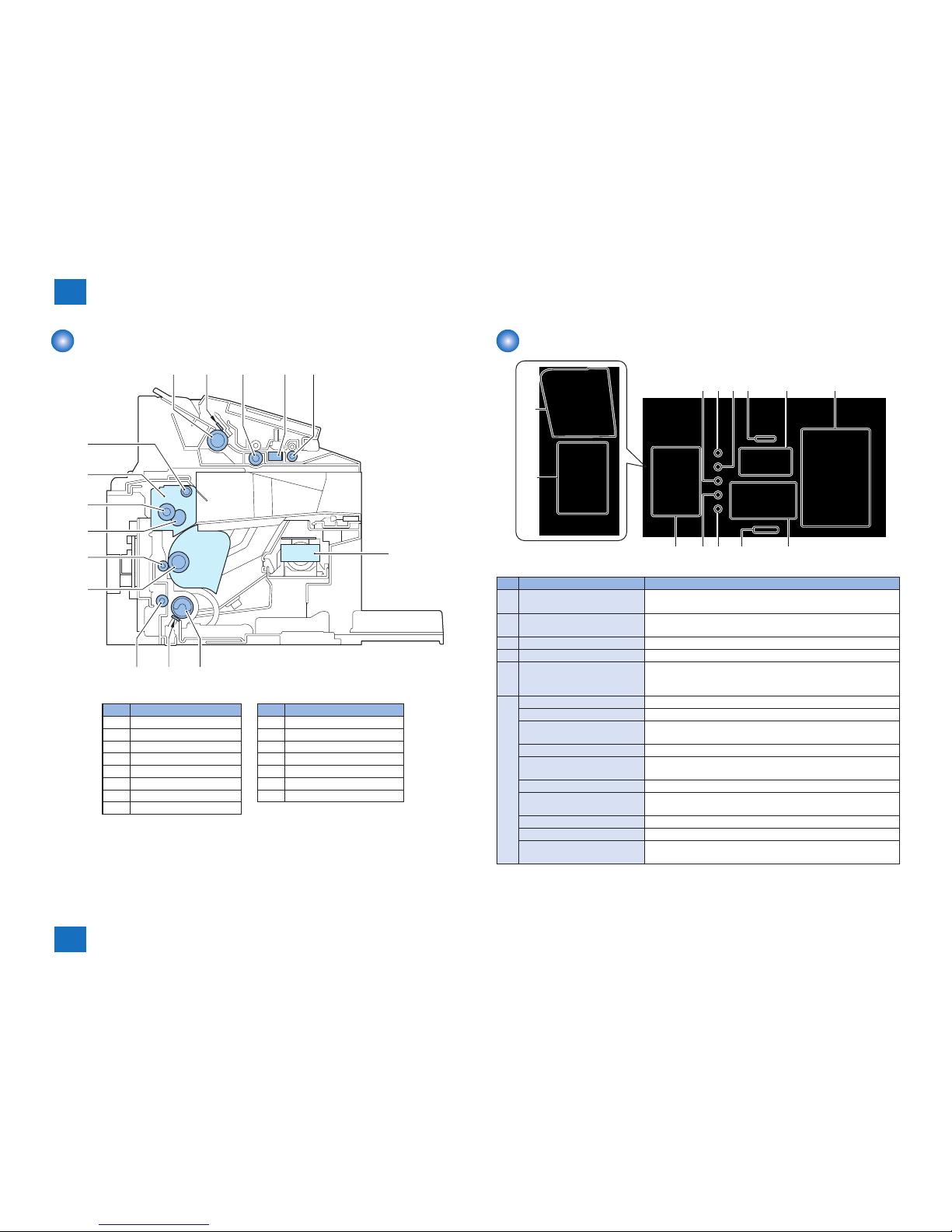
[1] [2] [3] [4] [5]
[6]
[7][8][9]
[10]
[11]
[12]
[13]
[14]
[15]
No. Name No. Name
[1] ADF Pickup Roller [9] Feed Roller
[2] ADF Separation Pad [10] Photosensitive Drum
[3] ADF Feed Roller [11] Transfer Roller
[4] CIS Unit [12] Fixing Film Unit
[5] ADF Delivery Roller [13] Fixing Pressure Roller
[6] Laser Scanner Unit [14] Fixing Assembly
[7] Pickup Roller [15] Delivery Roller
[8] Separation Pad
F-1-7
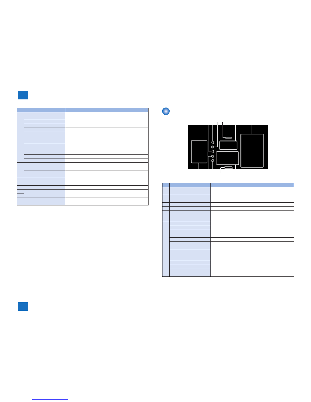
Operation Panel (L100 / L170 / L174)
[2] [3][1] [4] [5] [6]
[7][8][10]
[11]
[12]
[9]
[13]
No. Name Function
[1] [Redial] key Calls up the destination of last transmission. (This is enabled
only when the fax basic screen is displayed.)
[2] [Address Book] key Searches the destination registered to One-Touch Dial and
Coded Dial by name.
[3] [Coded Dial] key Species the destination registered to the Coded Dial.
[4] [FAX/COPY] key Switches the mode between copy and fax.
[5] LCD Displays a message or operation status. Displays menu,
selected item, texts, numbers and other information when
changing settings.
[6] [Menu] key Registers various settings.
[Paper Settings] key Species the paper size and type to place in the pickup tray.
[Report] key Prints a report and list. Also allows to set whether to
automatically print a report.
[Clear] key Deletes a text or number.
[Energy Saver] key/lamp Manually sets and cancels energy saver mode.Lights up in
green when in the energy saver mode.
Numeric keys ([0]-[9]) Enters a text or number.
[*] key Switches the text entry mode. Use to send the tone signal from
the dial line when sending fax.
[#] key Use to enter a signal.
[Stop] key Stops the job.
[Start] key/lamp Starts copy or fax operation.Lights up in green when a copy or
fax operation is in starting state.
F-1-8
1
1
1-10
1-10
Product Overview > Parts Name > Operation Panel (L150 / L150 CHN / L150 KOR / L154)
Product Overview > Parts Name > Operation Panel (L150 / L150 CHN / L150 KOR / L154)
No. Name Function
[7] [Status Monitor/Cancel]
key
Conrms and cancels a job. Also allows monitoring of this
product's status.
[Back] key Returns to the screen one layer before.
[▲] Key Selects the upper setting item or increases a setting value.
[▼] Key Selects the lower setting item or decreases a setting value.
[◄] Key Returns to the screen one layer before. Or moves the cursor
to the left. Press to lower the volume level when the fax tone is
playing.
[►] Key Proceeds to the screen one layer after. Or moves the cursor to
the right. Press to raise the volume level when the fax tone is
playing.
[OK] key Determines settings and registered data.
[Reset] key Resets settings.
[8] [Processing/Data] lamp Blinks in green when this product is running. Lights up in green
when a job is waiting.
[Error] lamp Blinks in orange when an error occurs. Or lights up in orange
instead.
[9] [Hook] key Push to dial with the telephone receiver of the external phone
on the hook.
[10] [Pause] key Inserts a pause in the fax number.
[11] [One-touch Speed Dial]
keys
Species the destination registered to the One-Touch Dial
1-30..
[12]
[13] Onetouch Cover By opening the Onetouch Cover, one-touch dials 16 to 30 are
enabled.
T-1-5
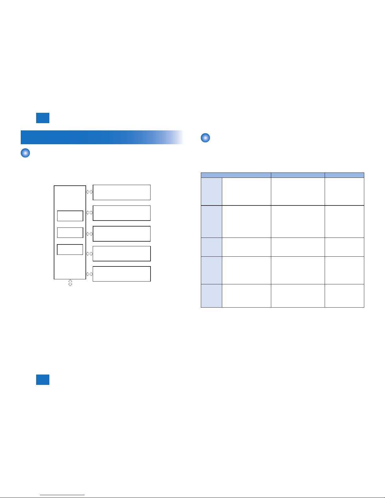
Operation Panel (L150 / L150 CHN / L150 KOR / L154)
[2] [3][1] [4] [5] [6]
[7][8][10]
[11]
[9]
No. Name Function
[1] [Redial] key Calls up the destination of last transmission. (This is enabled
only when the fax basic screen is displayed.)
[2] [Address Book] key Searches the destination registered to One-Touch Dial and
Coded Dial by name.
[3] [Coded Dial] key Species the destination registered to the Coded Dial.
[4] [FAX/COPY] key Switches the mode between copy and fax.
[5] LCD Displays a message or operation status. Displays menu,
selected item, texts, numbers and other information when
changing settings.
[6] [Menu] key Registers various settings.
[Paper Settings] key Species the paper size and type to place in the pickup tray.
[Report] key Prints a report and list. Also allows to set whether to
automatically print a report.
[Clear] key Deletes a text or number.
[Energy Saver] key/lamp Manually sets and cancels energy saver mode.Lights up in
green when in the energy saver mode.
Numeric keys ([0]-[9]) Enters a text or number.
[*] key Switches the text entry mode. Use to send the tone signal from
the dial line when sending fax.
[#] key Use to enter a signal.
[Stop] key Stops the job.
[Start] key/lamp Starts copy or fax operation.Lights up in green when a copy or
fax operation is in starting state.
F-1-9

1
1
1-11
1-11
Product Overview > Parts Name > Operation Panel (L150 / L150 CHN / L150 KOR / L154)
Product Overview > Parts Name > Operation Panel (L150 / L150 CHN / L150 KOR / L154)
No. Name Function
[7] [Status Monitor/Cancel]
key
Conrms and cancels a job. Also allows monitoring of this
product's status.
[Back] key Returns to the screen one layer before.
[▲] Key Selects the upper setting item or increases a setting value.
[▼] Key Selects the lower setting item or decreases a setting value.
[◄] Key Returns to the screen one layer before. Or moves the cursor
to the left. Press to lower the volume level when the fax tone is
playing.
[►] Key Proceeds to the screen one layer after. Or moves the cursor to
the right. Press to raise the volume level when the fax tone is
playing.
[OK] key Determines settings and registered data.
[Reset] key Resets settings.
[8] [Processing/Data] lamp Blinks in green when this product is running. Lights up in green
when a job is waiting.
[Error] lamp Blinks in orange when an error occurs. Or lights up in orange
instead.
[9] [Hook] key Push to dial with the telephone receiver of the external phone
on the hook.
[10] [Pause] key Inserts a pause in the fax number.
[11] [One-touch Speed Dial]
keys
Species the destination registered to the One-Touch Dial
1-15..
T-1-6

2
2
Technical Overview
Technical Overview
■Basic Conguration
■Controller System
■Original Exposure System
■Laser Exposure System
■Image Formation System
■Fixing System
■Pickup Feed System
2
2
2-2
2-2
Technical Overview > Basic Conguration > Basic Sequence > Basic Sequence of Operation
Technical Overview > Basic Conguration > Basic Sequence > Basic Sequence of Operation
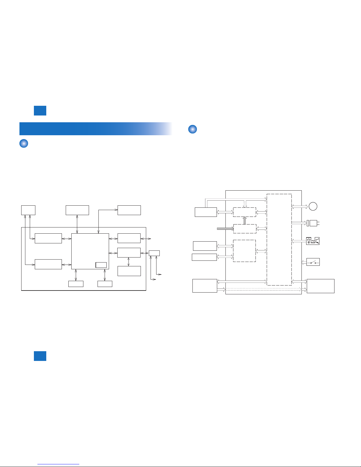
Basic Conguration
Conguration function
The machine may be broadly divided into the following 6 functional blocks: control
system,original exposure system, laser exposure system, image formation system, pickup
feed system and xing system.
Original exposure system
External device
Control system
Laser exposure system
Pickup feed system
Image formation system
Fixing system
Main
controler
Engine
controler
Power
supply
F-2-1
Basic Sequence
■Basic Sequence of Operation
The engine controller controls the operation sequence. The following table provides an outline
of machine operation occurring from when the power switch is turned on to when printing
ends and Main Motor (M1) stop, indicating the purposes of intervals and engine operation.
Interval Purpose Remarks
WAIT
(Wait)
From power-ON until initial
drive for Main Motor (M1) is
completed.
To clear potential from the drum
surface and to clean the transfer
roller.
Also to bring the heater
temperature up to the targeted
temperature.
Detect whether the
Toner cartridge is
installed or not.
STBY
(Standby)
From the end of the WAIT
period or the LSTR period
until the print command is
sent from the main controller.
Or, from the end of the LSTR
period until power switch is
turned OFF.
To keep the printer ready to
print.
INTR
(initial
rotation)
From the input of the print
command from the main
controller until the Pickup
Solenoid (SL1) is turned ON.
To stabilize the photosensitive
drum sensitivity in preparation
for printing. Also to clean the
transfer roller.
PRINT
(print)
From the end of the INTR
period until the Paper
Leading Edge Sensor
(PS751) detects the trailing
edge of paper.
To form image on the
photosensitive drum based on
the VIDEO (/VDO, VDO) signals
input from the main controller,
and to transfer the toner image
onto paper.
LSTR
(last
rotation)
From the end of PRINT
period until the Main Motor
(M1) stops.
To deliver the last paper
completely out of the printer.
Return to the INTR
period as soon as
another print command
is sent from the main
controller.
T-2-1
2
2
2-3
2-3
Technical Overview > Basic Conguration > Basic Sequence > Print Sequence
Technical Overview > Basic Conguration > Basic Sequence > Print Sequence
■Print Sequence
Fixing heater
CIS Unit
Document Feed Motor (M3)
Sequence
WAIT
Power-on
Start KEY
0.9
0.1
0.3
0.1
Max.1.5
2.4
0.5
0.5
0.06
0.06
0.9
2.0
2.0
Forcible emission
Forcible emission
Masking emission Masking emission Masking emission
1.3Print temperature control
Print command
Print command
Waiting for
a print command
0.5
1.1
0.1
0.8
Max.4.1
1.1
Cleaning bias Cleaning bias Print bias Cleaning bias
BD emission/
Forcible emission
Controls at 80 C
Relay
1
Print command
Scanner motor (M2)
Laser diode
Main motor (M1)
Pickup solenoid (SL1)
Leading edge sensor (PS751)
Fixing delivery sensor (PS701)
Primary charging bias (DC)
Developing bias (AC)
Developing bias (DC)
Transfer bias
STBY INTR PRINT LSTR STBY
(Unit:Seconds)
2
3
4
5
6
7
8
9
10
11
12
13
14
15
F-2-2

2
2
2-4
2-4
Technical Overview > Basic Conguration > Basic Sequence > Power-On Sequence
Technical Overview > Basic Conguration > Basic Sequence > Power-On Sequence
■Power-On Sequence
The sequences from the power-ON to the STBY period are described below.
1) Power-ON.
2) CPU initialization.
3) Video interface communication start.
4) Residual paper check.
Detecting paper presence by each sensor signaling.
5) Initial drive for Main Motor (M1).
6) Initial drive for Fixing Heater (H1).
Controlling xing temperature targeting for 120 deg C.
7) Initial drive of the Scanner Motor (M2).
8) High-voltage control.
Detect cartridge presence after primary charging AC bias is applied.
Cleaning transfer roller.
9) Failure/Abnormality check.
Detecting xing unit failure and door open during above periods.
2
2
2-5
2-5
Technical Overview > Controller System > Engine Controller > General description
Technical Overview > Controller System > Engine Controller > General description
Controller System
Main Controller
■Overview
The Main Controller receives print information from the Reader and external equipment
(computer, etc.). Video data is created from the received print information, and is sent to the
Engine Controller.
There are 2 types of print information from the external equipment: engine command data to
exchange the status or unique information of a printer and dot data for printing.
In the case of receiving dot data, video data is created and is sent to the Engine Controller.
In the case of receiving engine command data, printer status is returned to the external
equipment after communicating with the Engine Controller.
EXTERNAL
DEVICE
USB
INTERFACE
CONTROL PANEL
ENGINE
CONTROLLER
DRAM
MAIN CONTROLLER
Flash ROM
READER
CONVERTER
ANALOG TO DIGITAL
MOTOR DRIVER
DC/DC CONVERTER
CPU
ASIC
FAX MODEM
NCU
EXT
HANDSET
TEL
FAX LINE
F-2-3
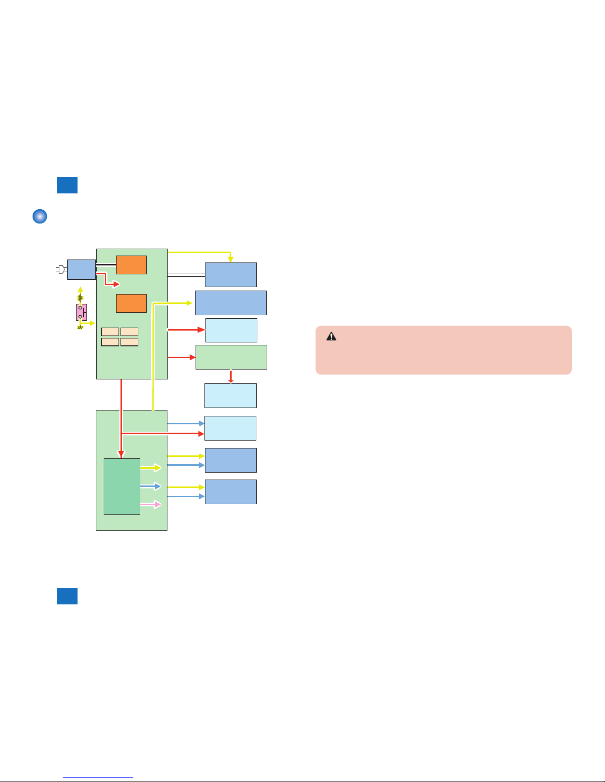
Engine Controller
■General description
Engine controller is the circuit to control the operation sequence of the host machine and it is
controlled by the CPU inside the engine controller.
When the Power Switch (SW1100) is turned ON and DC power is supplied through the low
voltage power inside engine controller, CPU starts the printer operation control.
Then, CPU drives the loads such as laser diode, motors and solenoids etc. according to the
image data that is input by the main controller when status becomes stand-by mode.
The following is the block diagram of this circuit.
AC input
Fixing
assembly
Motor
M
Transfer roller
High-voltage
power supply
Low-voltage
power supply
Laser scanner
unit
Solenoid
Main controller
Toner Cartridge
Sensor
CPU
Switch
Engine controller
Fixing control
F-2-4
2
2
2-6
2-6
Technical Overview > Controller System > Power Supply > Protective Functions
Technical Overview > Controller System > Power Supply > Protective Functions
Power Supply
■Power Supply
5.5V
3.3V
24V
3.3V
5.5V
5.5V
3.3V
Main Controller PCB
CIS Unit
Control Pan el Unit
5.5V
3.3V
1.0V
24V
DC/DC
Converte r
24V
3.3V
Engine Contr oller PCB
5V
Generatin g
Circuit
Protectio n
Circuit
Motor Drive r PCB
Laser Sca nner Unit
Fixing Ass embly
PickupSole noid
(SL1)
24V
Power
Supply
Assembly
24V
Main Motor
(M1)
24V
DF Motor
(M3)
3.3V
SW1100
FU101 FU201
FU202 FU203
F-2-5
■Protective Functions
●Power protective function
Low voltage power circuit carries the overcurrent preventive function against and overvoltage
preventive function that block the voltage output automatically to prevent the power circuit
brokerage when the overcurrent or overvoltage occur due to load errors such as short circuit
etc.
Thus, when the DC power cannot be output from the low voltage circuit, the protective
function against overcurrent or overvoltage may be working. Turn OFF the Power Switch
(SW1100) to x load errors and turn ON the Power Switch (SW1100) again (see CAUTION).
Also the circuit carries the 4 fuses (FU101, FU201, FU202, FU203) as another preventive
function. The fuses blow to block the power supply when overcurrent occurs in AC line.
CAUTION:
When restoring the low voltage power after protective function is activated, leave it for
2 minutes or more from turning off the Power Switch (SW1100) or plugging out before
turning ON.
●Safety function
The host machine equips the function of stopping 24V in part of the high voltage power unit to
avoid users and engineers from getting burned or electric shock.
When the cartridge door is opened, the Door Switch (SW501) is turned off and 24V supplied
to the high voltage power unit is shut.
Engine controller CPU determines the door open when the Door Switch (SW501) is turned
OFF.

2
2
2-7
2-7
Technical Overview > Controller System > Service Tasks > Notes on service tasks
Technical Overview > Controller System > Service Tasks > Notes on service tasks
Service Tasks
■At parts replacement
●When Replacing the Main Controller PCB
The Main Controller PCB stores data shown in the Backup Data List.
When replacing the Main Controller PCB, it is necessary to back up data in advance and
install it after replacing the PCB.
●Before Replacing the Main Controller PCB
• Check the version.
Service mode > COPIER > DISPLAY > VERSION
• Output the system data on a piece of paper as needed.
Service mode> COPIER > FUNCTION > MISC-P > OUTPUT >SYS-DAT
• Export address book data to the PC (backup of address book data)
●After Replacing the Main Controller PCB
• Check the version.
Service mode > COPIER > DISPLAY > VERSION
When the version differs, execute upgrading.
• Set country group.
Service mode > COPIER > OPTION > BODY > LOCALE
• Clear the data to enable the country group.
Service mode> COPIER > FUNCTION > CLEAR > ALL
The machine will be automatically restarted
If USA, EUROPE, ASIA, or OCEANIA is selected as the country group, make selections for
“Language” and ”Select Country/Region” when the machine is restarted.
The options available for “Language” and ”Select Country/Region” are shown in the
following list
Country group Language Select ountry/Region
USA English,French,Portuguese,Spanish United States(US),Canada(CA),
Brazil(BR),Mexico(MX),Other
Country group Language Select ountry/Region
EUROPE Bulgarian,Croatian,Czech,Danish,
Dutch,English,Estonian,Finnish,
French,German,Grrek,Hangarian,
Italian,Norwegian,Polish,Portuguese,
Romanian,Russian,Slovak,Slovene,
Spanish,Swedish,Turkish
Austria (AT),Belarus (BY),Belgium (BE),
Czech Republic (CZ),Denmark (DK),
Egypt (EG),Finland (FI),France (FR),
Germany (DE),Greece (GR),
Hungary (HU),Ieland (IE),Italy (IT),
Jodan (JO),Luxembourg (LU),
Netherland (NL),Norway (NO),
Poland (PL),Portugal (PT),Russia (RU),
Saudi Arabia (SA),Slovenia (SI),
South Africa (ZA),Spain (ES),
Sweden (SE),Switzerland (CH),
Ukraina (UA),Great Britain (GB),Other
ASIA Chinese (Simplied)
Chinese (Traditional),English,Frranch,
Japanese,Korean,Portuguese,Spanish,
Thai,Vietnamese
Hongkong (HK),Singapore (SG),
Malaysia (MY),Vetnam (VN),
Argentina (AR),Other (Asia),
Other (Latin America)
OCEANIA Chinese (Simplied)
Chinese (Traditional),English,Frranch,
Japanese,Korean,Portuguese,Spanish,
Thai,Vietnamese
Australia (AU),New Zealand (NZ),
Other
• Make settings of system data as needed.
• Import address book data from the PC (installation of address book data)
■Maintenance
No periodically replaced parts, durable parts or periodical service is set for this product.
■Notes on service tasks
None.
T-2-2