


Feb 6 2008
Service Manual
L90/L140/L160/L230 Series
FAX-L140


Application
This manual has been issued by Canon Inc. for qualified persons to learn technical theory, installa tion, ma intenance, and repair
of products. This manual covers all localities where the products are sold. For this reason, there may be information in this
manual that does not apply to your locality.
Corrections
This manual may contain technical inaccuracies or typographical errors due to improvements or changes in products. When
changes occur in applicable products or in the contents of this manual, Canon will release technical information as the need
arises. In the event of major changes in the contents of this manual over a long or short period, Canon will issue a new edition
of this manual.
The following paragraph does not apply to any countries where such provisions are inconsistent with local law.
Trademarks
The product names and company names used in this manual are the registered trademarks of the individual companies.
Copyright
This manual is copyrighted with all rights reserved. Under the copyright laws, this manual may not be copied, reproduced or
translated into another language, in whole or in part, without the written consent of Canon Inc.
COPYRIGHT © 2001 CANON INC.
Printed in Japan
Caution
Use of this manual should be strictly supervised to avoid disclosure of confidential information.
Introduction
Symbols Used
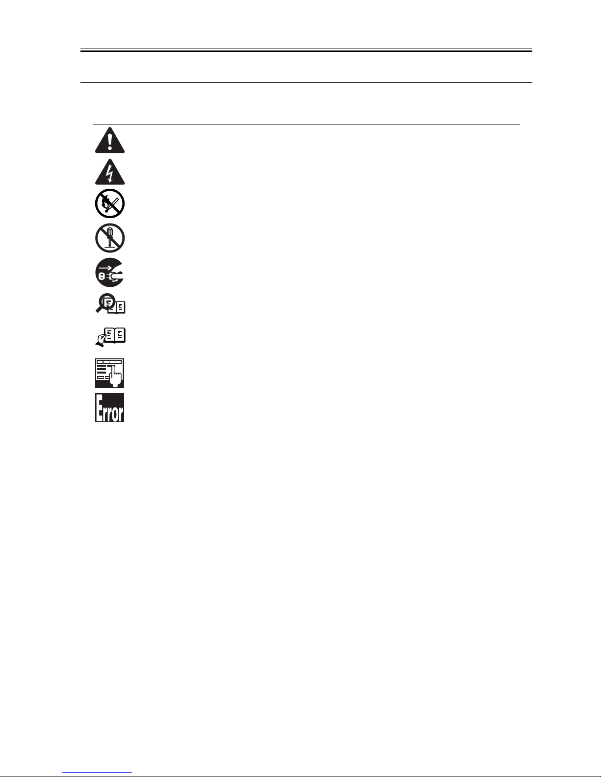
This documentation uses the following symbols to indicate special information:
Symbol Description
Indicates an item of a non-specific nature, possibly classified as Note, Caution, or Warning.
Indicates an item requiring care to avoid electric shocks.
Indicates an item requiring care to avoid combustion (fire).
Indicates an item prohibiting disassembly to avoid electric shocks or problems.
Indicates an item requiring disconnection of the power plug from the electric outlet.
Indicates an item intended to provide notes assisting the understanding of the topic in question.
Indicates an item of reference assisting the understanding of the topic in question.
Provides a description of a service mode.
Provides a description of the nature of an error indication.
Memo
REF.

Introduction
The following rules apply throughout this Service Manual:
1. Each chapter contains sections explaining the purpose of specific functions and the relationship between electrical and mechanical systems with reference to the timing of operation.
In the diagrams, represents the path of mechanical drive; where a signal name accompanies the symbol , the arrow indicates the
direction of the electric signal.
The expression "turn on the power" m eans flipping on the power switch, closing the front door, and closing the delivery unit door, which results in
supplying the machine with power.
2. In the digital circuits, '1'is used to indicate that the voltage level of a given signal is "High", while '0' is used to indicate "Low".(The voltage value, however, differs from circuit to circuit.) In addition, the asterisk (*) as in "DRMD*" indicates that the DRMD signal goes on when '0'.
In practically all cases, the internal mechanisms of a microprocessor cannot be checked in the fi eld. Therefore, the operations of the microprocessors
used in the machines are not discussed: they are explained in terms of from sensors to the input of the DC controller PCB and from the output of the
DC controller PCB to the loads.
The descriptions in this Service Manual are subject to change without notice for product improvement or other purposes, and major changes will be communicated in the form of Service Information bulletins.
All service persons are expected to have a good understanding of the contents of this Service Manual and all relevant Service Information bulletins and be
able to identify and isolate faults in the machine."


Contents
Contents
Chapter 1 Introduction
1.1 Product Specifications................................................................................................................................1- 1
1.1.1 Names of Parts.................................... .................................................. ....................................... ... ........................1- 1
1.1.1.1 External View........................................................................................................................................................................... 1- 1
1.1.1.2 Operation Panel....................................................................................................................................................................... 1- 2
1.1.2 Safety ......................................................................................................................................................................1- 2
1.1.2.1 Safety of Laser Light................................................................................................................................................................ 1- 2
1.1.2.2 Handling the Laser Unit ...........................................................................................................................................................1- 3
1.1.2.3 Safety of Toner ........................................................................................................................................................................1- 3
1.1.2.4 Point to Note about Fire........................................................................................................................................................... 1- 3
1.1.2.5 Point to Note about Battery Replacement................................................................................................................................ 1- 3
1.1.3 Function List............................ ... ................................................... .. ........................................................................1- 4
1.1.3.1 Scanning Range (Transmission).............................................................................................................................................. 1- 4
1.1.3.2 Printing Range (Reception)...................................................................................................................................................... 1- 4
1.1.3.3 Printing Range (Printer) ........................................................................................................................................................... 1- 5
1.1.3.4 System Requirements for Printer Driver .................................................................................................................................. 1- 5
Chapter 2 Document Feed and Exposure System
2.1 Overview/Configuration ..............................................................................................................................2- 1
2.1.1 Overview..................................................................................................................................................................2- 1
2.2 Parts Replacement Procedure ...................................................................................................................2- 1
2.2.1 Separation Guide Unit.................................... ... ..................................................... ....................................... ..........2- 1
2.2.1.1 Preparation for Removing the Scraper ....................................................................................................................................2- 1
2.2.1.2 Removing the Scraper ............................................................................................................................................................. 2- 1
2.2.2 Contact Sensor.................................... ....................................................................................................................2- 2
2.2.2.1 Preparation for Removing the Contact Sensor ........................................................................................................................ 2- 2
2.2.2.2 Removing the Contact Sensor.................................................................................................................................................2- 2
2.2.3 Separation Roller................................... ..................................................................................................................2- 3
2.2.3.1 Preparation for Removing the Document Separation Roller.................................................................................................... 2- 3
2.2.3.2 Removing the Document Separation Roller............................................................................................................................. 2- 3
2.2.4 Feed Roller.......................................................................................................... ..................................... .. .............2- 4
2.2.4.1 Preparation for Removing the Document Feed Roller.............................................................................................................2- 4
2.2.4.2 Removing the Document Feed Roller...................................................................................................................................... 2- 4
2.2.5 Reader Unit ...................................................................................................... ... ....................................... ... ..........2- 5
2.2.5.1 Preparation for Removing the Reader Unit.............................................................................................................................. 2- 5
2.2.5.2 Removing the Reader Unit.......................................................................................................................................................2- 5
2.2.6 Document Feed Motor.............................................................................................................................................2- 5
2.2.6.1 Preparation for Removing the Document Feed Motor ............................................................................................................. 2- 5
2.2.6.2 Removing the Document Feed Motor......................................................................................................................................2- 5
2.2.7 DS/DES Sensor.......................................................................................................................................................2- 5
2.2.7.1 Preparation for Removing the DS/DES Sensor ....................................................................................................................... 2- 5
2.2.7.2 Removing the DS/DES Sensor................................................................................................................................................2- 6
Chapter 3 Laser Exposure
3.1 Overview/Configuration ..............................................................................................................................3- 1
3.1.1 Overview..................................................................................................................................................................3- 1
3.2 Parts Replacement Procedure ...................................................................................................................3- 1
3.2.1 Laser/Scanner Unit..................................................................................................................................................3- 1
3.2.1.1 Preparation for Removing the Laser/Scanner Unit .................................................................................................................. 3- 1
3.2.1.2 Removing the Laser/Scanner Unit........................................................................................................................................... 3- 1

Contents
Chapter 4 Image Formation
4.1 Overview/Configuration..............................................................................................................................4- 1
4.1.1 Overview..................................................................................................................................................................4- 1
4.2 Toner Cartridge ..........................................................................................................................................4- 1
4.2.1 Display the message................................................................................................................. ... ...........................4- 1
4.3 Parts Replacement Procedure ...................................................................................................................4- 1
4.3.1 Transfer Charging Roller.................................................................................................................................. ........4- 1
4.3.1.1 Removing the Transfer Charging Roller ..................................................................................................................................4- 1
Chapter 5 Pickup and Feed System
5.1 Overview/Configuration..............................................................................................................................5- 1
5.1.1 Overview..................................................................................................................................................................5- 1
5.2 Detection Jams........ ... ... ... .......................................... ... .... ... ... ... ................................................................5- 1
5.2.1 Jam Detection Outline..................................................................................................................... .........................5- 1
5.2.1.1 Type of Jams ........................................................................................................................................................................... 5- 1
5.2.2 Delay Jams......................................................................................................................................................... ... ..5- 2
5.2.2.1 Pickup Delay Jam .................................................................................................................................................................... 5- 2
5.2.2.2 Delivery Delay Jam..................................................................................................................................................................5- 2
5.2.3 Stationary Jams.................... ... ... .................................................. ... ....................................... .................................5- 2
5.2.3.1 Pickup Stationary Jam ............................................................................................................................................................. 5- 2
5.2.3.2 Delivery Stationary Jam...........................................................................................................................................................5- 2
5.2.4 Other Jams.......................................................................................................................... ... .................................5- 2
5.2.4.1 Fixing Wrap Jam...................................................................................................................................................................... 5- 2
5.2.4.2 Initial Jam................................................................................................................................................................................. 5- 2
5.2.4.3 Cover Open Jam...................................................................................................................................................................... 5- 2
5.3 Parts Replacement Procedure ...................................................................................................................5- 2
5.3.1 Pickup Unit............................................................................................................. ... ...............................................5- 2
5.3.1.1 Preparation for Removing the Paper Pickup Unit .................................................................................................................... 5- 2
5.3.1.2 Removing the Paper Pickup Unit.............................................................................................................................................5- 2
5.3.2 Cassette Pickup Roller.................................................................................................................. .. .........................5- 3
5.3.2.1 Removing the Cassette Pickup Roller ..................................................................................................................................... 5- 3
5.3.3 Cassette Pickup Solenoid........................................................................................................................................5- 3
5.3.3.1 Preparation for Removing the Cassette Pickup Solenoid........................................................................................................5- 3
5.3.3.2 Removing the Cassette Pickup Solenoid................................................................................................................................. 5- 3
5.3.4 Cassette Separation Pad................................................................................................................................. ... .....5- 3
5.3.4.1 Removing the Cassette Separation Pad.................................................................................................................................. 5- 3
5.3.5 Main Motor................................................................................................................................. ..............................5- 4
5.3.5.1 Preparation for Removing the Main Motor...............................................................................................................................5- 4
5.3.5.2 Removing the Main Motor........................................................................................................................................................5- 4
Chapter 6 Fixing System
6.1 Overview/Configuration..............................................................................................................................6- 1
6.1.1 Overview..................................................................................................................................................................6- 1
6.2 Various Control Mechanisms ............................................ ... ... ... .... .......................................... ..................6- 1
6.2.1 Controlling the Temperature of the Fixing Unit........................................................................................................6- 1
6.2.1.1 Heater Temperature Control....................................................................................................................................................6- 1
6.3 Protection Function ....................................................................................................................................6- 3
6.3.1 Protective Mechanisms............................................................................................................................................6- 3
6.3.2 Detection of a Fault......................................................... ....................................................................................... ..6- 3
6.4 Parts Replacement Procedure ...................................................................................................................6- 3
6.4.1 Fixing Unit................................................. .. ... ................................................... ....................................... ................6- 3
6.4.1.1 Preparation for Removing the Fixing Unit................................................................................................................................6- 3
6.4.1.2 Removing the Fixing Unit......................................................................................................................................................... 6- 3
6.4.2 Fixing Film Unit....................................................................... ... ..............................................................................6- 3
6.4.2.1 Preparation for Removing the Fixing Film Unit ........................................................................................................................ 6- 3

Contents
6.4.2.2 Removing the Fixing Film Unit.................................................................................................................................................6- 3
6.4.3 Fixing Pressure Roller.................................................................................................................. ... ........................6- 4
6.4.3.1 Preparation for Removing the Fixing Pressure Roller..............................................................................................................6- 4
6.4.3.2 Removing the Fixing Pressure Roller ......................................................................................................................................6- 4
Chapter 7 External and Controls
7.1 Power Supply .............................................................................................................................................7- 1
7.1.1 Protection Function................................................................................................................................... ...............7- 1
7.1.1.1 Protective Mechanisms............................................................................................................................................................ 7- 1
7.1.2 Backup Battery........................................................................................................................................................7- 1
7.1.2.1 Battery-backed up Data ........................................................................................................................................................... 7- 1
7.2 Parts Replacement Procedure ...................................................................................................................7- 1
7.2.1 Front Cover................................................................................................................................... ...........................7- 1
7.2.1.1 Preparation for Detaching the Front Cover..............................................................................................................................7- 1
7.2.1.2 Detaching the Front Cover....................................................................................................................................................... 7- 1
7.2.2 Rear Cover..............................................................................................................................................................7- 1
7.2.2.1 Preparation for Detaching the Rear Cover...............................................................................................................................7- 1
7.2.2.2 Detaching the Rear Cover .......................................................................................................................................................7- 1
7.2.3 Right Cover................................................................................................................................... ...........................7- 2
7.2.3.1 Preparation for Detaching the Right Cover..............................................................................................................................7- 2
7.2.3.2 Detaching the Right Cover....................................................................................................................................................... 7- 2
7.2.4 Left Cover................................................................................................................................................. ...............7- 2
7.2.4.1 Preparation for Detaching the Left Cover ................................................................................................................................7- 2
7.2.4.2 Detaching the Left Cover ......................................................................................................................................................... 7- 2
7.2.5 External Cover......................................................................................................................... .. ... ...........................7- 2
7.2.5.1 Removing the Document Feed Tray and the Paper Tray Cover.............................................................................................. 7- 2
7.2.6 Upper Cover............................................................................................................................................................7- 3
7.2.6.1 Preparation for Detaching the Upper Cover.............................................................................................................................7- 3
7.2.6.2 Detaching the Upper Cover .....................................................................................................................................................7- 3
7.2.7 Cartridge Cover.................................................................................................................... ... ................................7- 3
7.2.7.1 Preparation for Detaching the Cartridge Cover........................................................................................................................ 7- 3
7.2.7.2 Detaching the Cartridge Cover ................................................................................................................................................7- 3
7.2.8 Operation Panel Unit .................................................................................................................... ...........................7- 4
7.2.8.1 Preparation for Removing the Control Panel Unit.................................................................................................................... 7- 4
7.2.8.2 Removing the Control Panel Unit............................................................................................................................................. 7- 4
7.2.9 SCNT Board............................................................................................................................................................7- 4
7.2.9.1 Preparation for Removing the SCNT Board.............................................................................................................................7- 4
7.2.9.2 Removing the SCNT Board .....................................................................................................................................................7- 4
7.2.10 DCNT Board..........................................................................................................................................................7- 4
7.2.10.1 Preparation for Removing the DCNT Board........................................................................................................................... 7- 4
7.2.10.2 Removing the DCNT Board ...................................................................................................................................................7- 4
7.2.11 High-voitage Power Supply PCB...........................................................................................................................7- 5
7.2.11.1 Preparation for Removing the High-Voltage Power Supply Board......................................................................................... 7- 5
7.2.11.2 Removing the High-Voltage Power Supply Board .................................................................................................................7- 5
7.2.12 Powwer Supply PCB................................................................................................................................. .............7- 6
7.2.12.1 Preparation for Removing the Power Supply Board ..............................................................................................................7- 6
7.2.12.2 Removing the Power Supply Board ....................................................................................................................................... 7- 6
7.2.13 Top Sensor............................................................................................................................................................7- 6
7.2.13.1 Preparation for Removing the Paper Leading Edge / the Paper Width Sensor PCB.............................................................7- 6
7.2.13.2 Removing the Paper Leading Edge/ the Paper Width Sensor PCB.......................................................................................7- 6
7.2.14 Paper Delivery Sensor...........................................................................................................................................7- 6
7.2.14.1 Preparation for Removing the Paper Delivery Sensor PCB................................................................................................... 7- 6
7.2.14.2 Removing the Paper Delivery Sensor PCB............................................................................................................................7- 6
7.2.15 Toner Sensor.........................................................................................................................................................7- 6
7.2.15.1 Preparation for Removing the Toner Sensor ......................................................................................................................... 7- 6
7.2.15.2 Removing the Toner Sensor .................................................................................................................................................. 7- 7
7.2.16 Paper Width Sensor................................................................................................................................ .. .............7- 7
7.2.16.1 Preparation for Removing the Paper Width Sensor PCB....................................................................................................... 7- 7

Contents
7.2.16.2 Removing the Paper Width Sensor PCB ............................................................................................................................... 7- 7
7.2.17 Speaker..................................................................................................................................................................7- 7
7.2.17.1 Preparation for Removing the Speaker.................................................................................................................................. 7- 7
7.2.17.2 Removing the Speaker........................................................................................................................................................... 7- 7
Chapter 8 Maintenance and Inspection
8.1 Periodically Replaced Parts .................................................... ... .... ... .........................................................8- 1
8.1.1 Periodic Replacement Parts .................................................................................................................................. ..8- 1
8.2 Consumables .............................................................................................................................................8- 1
8.2.1 Consumable................................................................................................................................................ ... ..........8- 1
8.3 Periodical Service.......................................................................................................................................8- 1
8.3.1 Scheduled service Parts............................................................................................................ ... ...........................8- 1
8.4 Cleaning .....................................................................................................................................................8- 1
8.4.1 Items Requiring Cleaning........................................ .. ... ..................................................... ..................................... ..8- 1
8.4.2 Cleaning Method (external covers)..........................................................................................................................8- 2
8.4.3 Cleaning Method (scanning unit)......................... ... ..................................................... ... .................................... .....8- 2
8.4.4 Cleaning (printer unit).............................................................................................................................. .. ..............8- 3
Chapter 9 Measurement and Adjustments
9.1 Image Adjustments.....................................................................................................................................9- 1
9.1.1 Adjusting the Paper Margin......................................................................................................................................9- 1
9.1.2 Read Adjustment ............................................................................................................................... ... ...................9- 1
9.1.3 Print Adjustment................................................................................................................... ....................................9- 1
Chapter 10 Correcting Faulty Images
10.1 Troubleshooting......................................................................................................................................10- 1
10.1.1 Phenomenon Table..............................................................................................................................................10- 1
10.1.1.1 Symptoms ............................................................................................................................................................................ 10- 1
10.2 Outline of Electrical Components ...........................................................................................................10- 1
10.2.1 Sensor................................................................................................................................................. ... ..............10- 1
10.2.1.1 Arrangement of Sensors and Switches................................................................................................................................ 10- 1
10.2.2 PCBs....................................................................................................................................................................10- 2
10.2.2.1 Arrangement of PCBs .......................................................................................................................................................... 10- 2
Chapter 11 Error Code
11.1 Error Code.............................................................................................................................................. 11- 1
11.1.1 Error Code................................................................................................................................ ... .. .......................11- 1
Chapter 12 Service Mode
12.1 Outline ....................................................................................................................................................12- 1
12.1.1 Service Data Setting ............................................. .. ... ................................................... .. .....................................12- 1
12.1.2 Service Data Entry Method.................. ... .. ................................................... ... .....................................................12- 1
12.1.3 Service Data menu.................................................................................... ... ....................................... .................12- 2
12.2 Default Settings ......................................................................................................................................12- 3
12.2.1 SSSW Default Settings........................................................................................................................................12- 3
12.3 Service Soft Switch Settings (SSSW)...................................................................................................12- 10
12.3.1 Outline................................................................................................................................................................12- 10
12.3.1.1 Explanation of SOFT SWITCH........................................................................................................................................... 12- 10
12.3.2 SSSW-SW02:.....................................................................................................................................................12- 10
12.3.2.1 List of Functions.................................................................................................................................................................12- 10
12.3.2.2 Details of Bit 2 and Bit 3..................................................................................................................................................... 12- 11
12.3.3 SSSW-SW10......................................................................................................................................................12- 11

Contents
12.3.3.1 List of Functions................................................................................................................................................................. 12- 11
12.3.3.2 Details of Bit 1....................................................................................................................................................................12- 11
12.3.3.3 Details of Bit 2....................................................................................................................................................................12- 11
12.3.4 SSSW-SW16.....................................................................................................................................................12- 11
12.3.4.1 List of Functions................................................................................................................................................................. 12- 11
12.3.4.2 Details of Bit 3....................................................................................................................................................................12- 12
12.3.5 SSSW-SW30.....................................................................................................................................................12- 12
12.3.5.1 List of Functions................................................................................................................................................................. 12- 12
12.3.5.2 Details of Bit 7 and Bit 8..................................................................................................................................................... 12- 12
12.3.6 SSSW-SW37.....................................................................................................................................................12- 12
12.3.6.1 List of Functions................................................................................................................................................................. 12- 12
12.3.6.2 Details of Bit 1 through Bit 6...............................................................................................................................................12- 13
12.3.7 SSSW-SW51.....................................................................................................................................................12- 13
12.3.7.1 List of Functions................................................................................................................................................................. 12- 13
12.3.7.2 Details of Bit 3 and Bit 4..................................................................................................................................................... 12- 13
12.3.8 SSSW-SW54.....................................................................................................................................................12- 14
12.3.8.1 List of Functions................................................................................................................................................................. 12- 14
12.3.8.2 Details of Bit 6 and Bit 7..................................................................................................................................................... 12- 14
12.3.8.3 Details of Bit 8....................................................................................................................................................................12- 14
12.4 Report Output (REPORT).....................................................................................................................12- 15
12.4.1 SERVICE DATA LIST.................................................................. .. ....................................................................12- 15
12.5 Test Mode (TEST) ................................................................................................................................12- 15
12.5.1 Overview............................................................................................................................................................12- 15
12.5.1.1 Test Mode Overview .......................................................................................................................................................... 12- 15
12.5.1.2 Test Mode Menu ................................................................................................................................................................ 12- 15
12.5.2 Faculty Test.......................................................................................................................................................12- 15
12.5.2.1 PRINT TEST PATTERN ....................................................................................................................................................12- 15
12.5.2.2 ADF FEED TEST ............................................................................................................................................................... 12- 16
12.5.2.3 Sensor Tests...................................................................................................................................................................... 12- 16
Chapter 13 Service Tools
13.1 Service Tools........................................................................................ ... ... ... .........................................13- 1
13.1.1 Solvent/Oil List.....................................................................................................................................................13- 1

Contents

Chapter 1 Introduction


Contents
Contents
1.1 Product Specifications....................................................................................................................................................1-1
1.1.1 Names of Parts ............................................................................................................................................................................. 1-1
1.1.1.1 External View..................................................................................................................................................................................................1-1
1.1.1.2 Operation Panel...............................................................................................................................................................................................1-2
1.1.2 Safety ........................................................................................................................................................................................... 1-2
1.1.2.1 Safety of Laser Light.......................................................................................................................................................................................1-2
1.1.2.2 Handling the Laser Unit ..................................................................................................................................................................................1-3
1.1.2.3 Safety of Toner................................................................................................................................................................................................1-3
1.1.2.4 Point to Note about Fire ..................................................................................................................................................................................1-3
1.1.2.5 Point to Note about Battery Replacement.......................................................................................................................................................1-3
1.1.3 Function List ................................................................................................................................................................................ 1-4
1.1.3.1 Scanning Range (Transmission) ...... ......................................... .......................................... . ...........................................................................1-4
1.1.3.2 Printing Range (Reception).............................................................................................................................................................................1-4
1.1.3.3 Printing Range (Printer) ..................................................................................................................................................................................1-5
1.1.3.4 System Requirements for Printer Driver.........................................................................................................................................................1-5

Chapter 1
1-1
1.1 Product Specifications
1.1.1 Names of Parts
1.1.1.1 External View
0018-4889
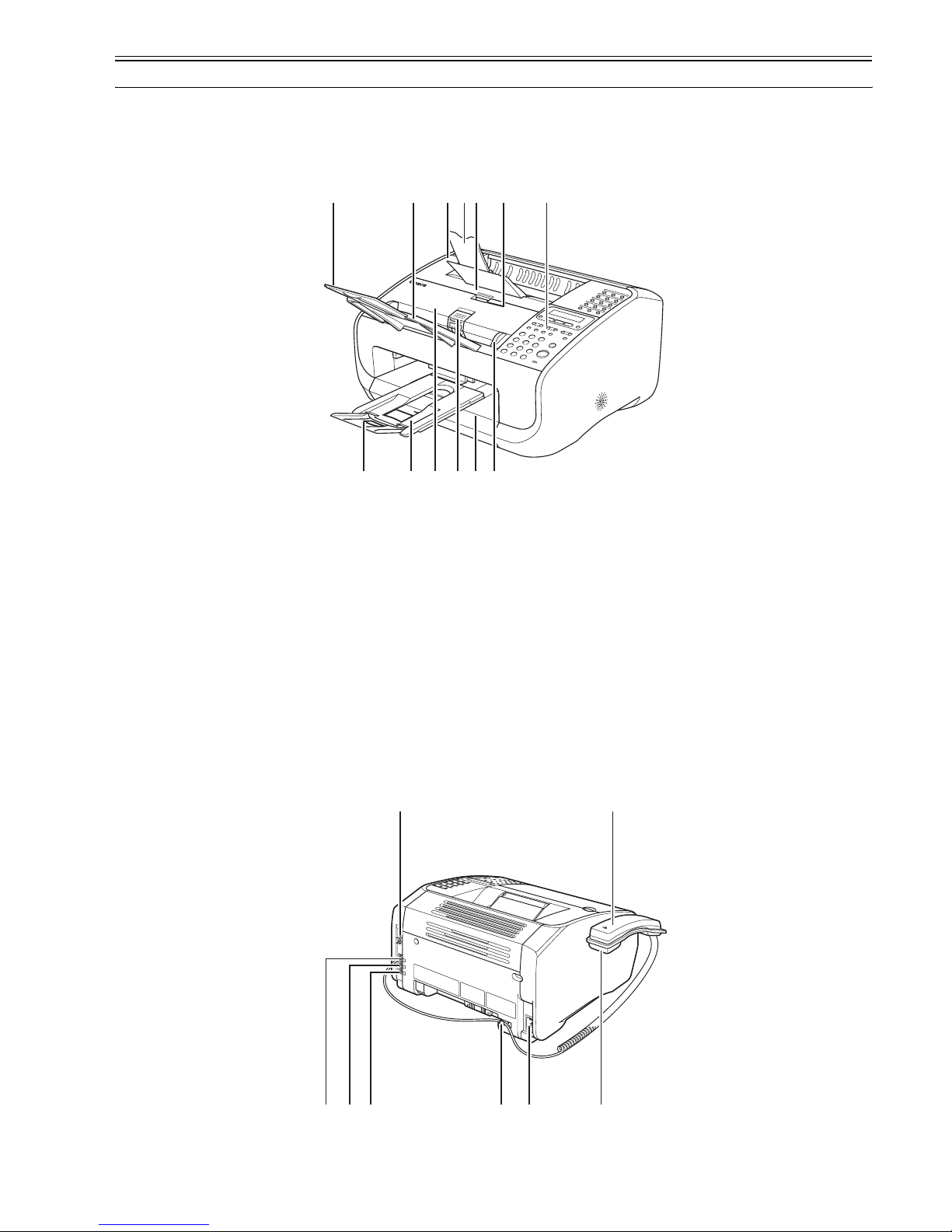
Front
F-1-1
T-1-1
Rear
F-1-2
[A] Paper delivery tray [H] Automatic document feeder (ADF)
[B] Paper delivery tray extension [I] Document feeder tray
[C] Cartridge cover [J] Document feeder tray extention
[D] Notch [K] Document delivery tray
[E] Operation panel [L] Document delivery tray extension
[F] Document release lever [M] Paper stack cover
[G] Document guides
ABI
J
C D E
F GMKL H
P N
OUT
RSQ
Chapter 1
1-2
T-1-2
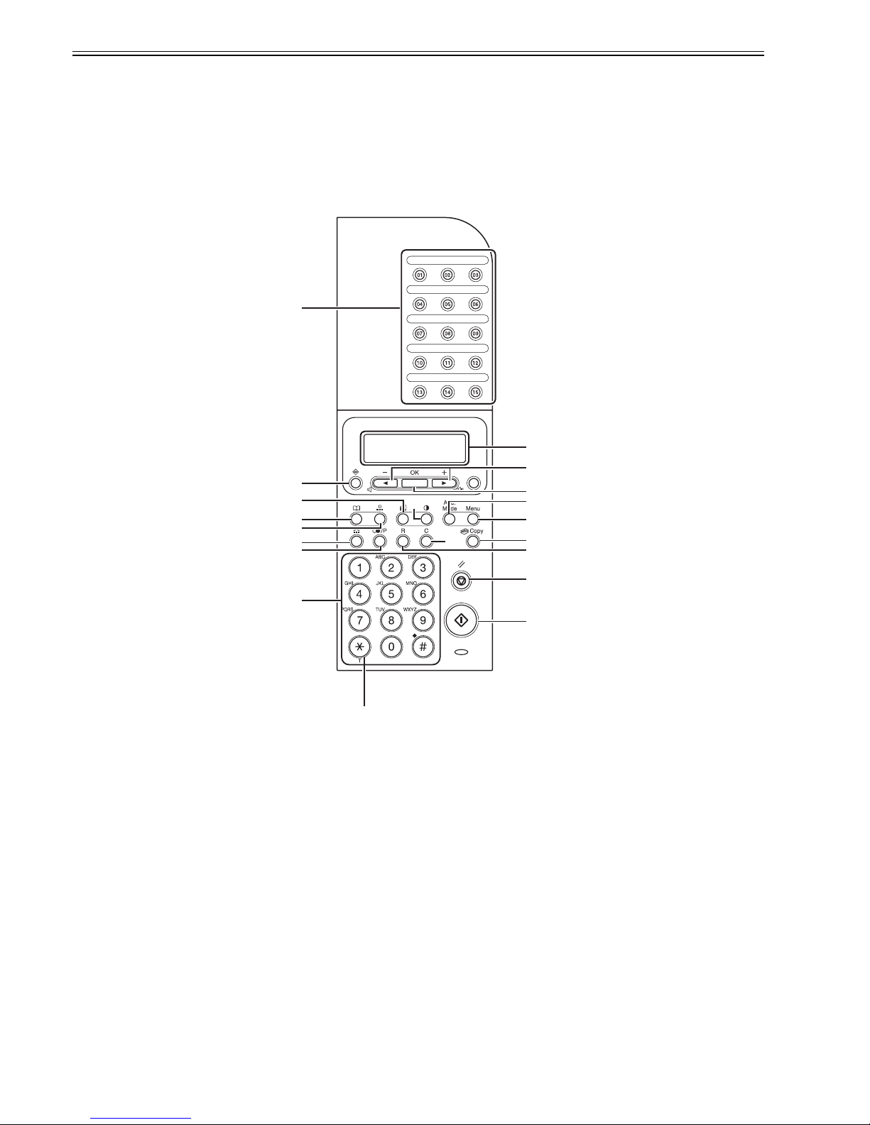
1.1.1.2 Operation Panel
0018-4891
F-1-3
T-1-3
1.1.2 Safety
1.1.2.1 Safety of Laser Light
0018-4892
Laser radiation could be hazardous to the human body. For this reason, laser radiation emitted inside this machine is hermetically sealed within the protective housing and external cover. No radiation can leaak from the machine in the normal operation of the product by the user.
[N] Handset (Optional) [R] External device jack
[O] Handset cradle (Optional) [S] Line jack
[P] USB port [T] Handset cable retainer(Optional)
[Q] Handset jack [U] Power socket
[A] One-touch speed dialing button [K] Hook button
[B] LCD [L] Numeric buttons
[C] Additional mode button [M] Tone butt on
[D] Menu button [N] Copy button
[E] Status button [O] +/- button
[F] Image Quality button [P] Density button
[G] Directory button [Q] OK button
[H] Coded dial button [R] Clear button
[I] Redial/Pause button [S] Stop/Reset button
[J] R button [T] Start button
M
R
P
A
H
K
I
G
E
L
F
S
T
Q
B
C
D
J
N
O

Chapter 1
1-3
1.1.2.2 Handling the Laser Unit
0018-4894
The laser scanner unit emits invisible laser light inside it. If exposed to laser light, the human eye can irreparably be damaged. Never attempt to disassembl e the
laser scanner unit. (It is not designed for servicing in the field).
The covers around the laser scanner unit are identified by the following label [1].
F-1-4
1.1.2.3 Safety of Toner
0018-4895
The machine's toner is a non-toxic material composed of plastic, iron, and small amounts of dye.
Do not put the toner into fire. It may explode.
Toner on the Skin or Clothes
1. If your skin or clothes came into contact with toner, wash with water at once.
2. Do not use warm or hot water, which will cause the toner to jell, permanently fusing it with the fibers of the clothes.
3. Do not bring toner into contact with vinyl material. They are likely to react with each other.
1.1.2.4 Point to Note about Fire
0018-4896
It is dangerous to throw lithium batteries and parts and components containing flammable substances, such as cartridges, etc., into fire. Such parts and components
must be disposed of in accordance with local laws and regulations.
1.1.2.5 Point to Note about Battery Replacement
0018-4897
The batteries must be replaced correctly to avoid explosion.
Do not replace any battery with one not indicated for the machine, i.e., use one of the same type or equivalent. Be sure to dispose of used batteries according to
local laws and regulations.
[1]
Chapter 1
1-4
1.1.3 Function List
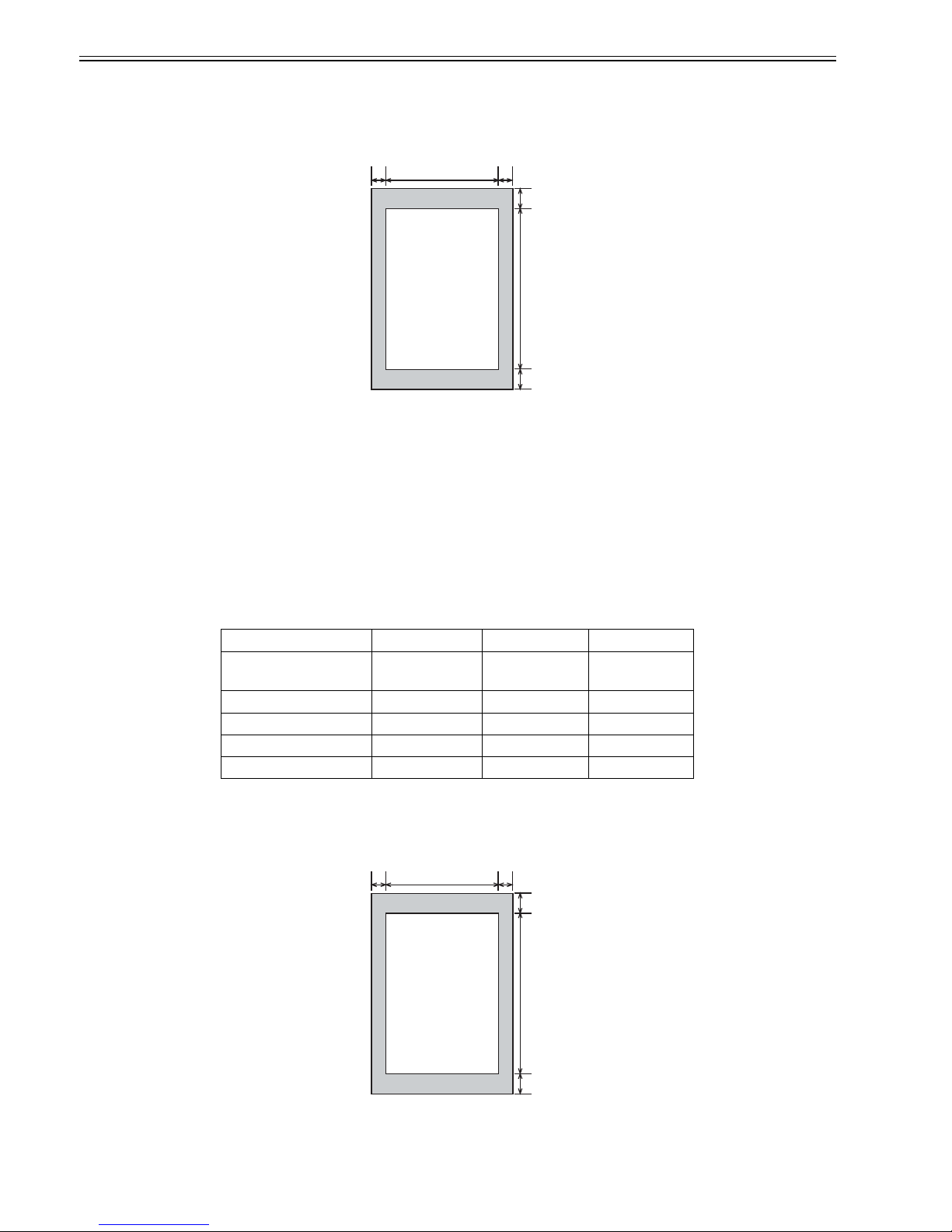
1.1.3.1 Scanning Range (Transmission)
0018-4882
F-1-5
T-1-4
T-1-5
1.1.3.2 Printing Range (Reception)
0018-4883
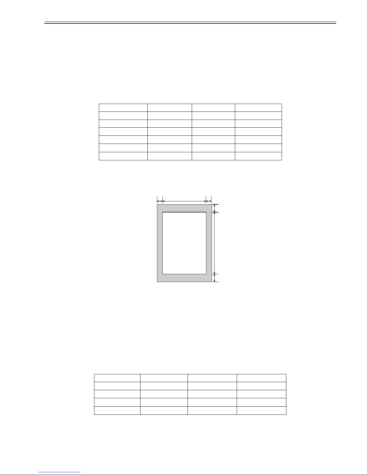
F-1-6
[1] Document leading edge [6] Effective scanning length
[2] Left margin [7] Bottom margin
[3] Effective scanning width [8] Scanning drop out range
[4] Right margin [9] Scanning range
[5] Top margin [10] Document trailing edge
Item A4 Letter Legal
Effective scanning width 208 +1.0/-1.0 mm 214 +1.0/-1.0 mm 214 +1.0/-1.0 mm
Left margin 1.0 +2.0/-2.0 mm 1.0 +2.0/-2.0 mm 1.0 +2.0/-2.0 mm
Right margin (1.0 mm) (1.0 mm) (1.0 mm)
Top margin (ADF) 2.0 +2.0/-2.0 mm 2.0 +2.0/-2.0 mm 2.0 +2.0/-2.0 mm
Bottom margin (ADF) 2.0 +2.0/-2.0 mm 2.0 +2.0/-2.0 mm 2.0 +2.0/-2.0 mm
[9]
[8]
[4][2]
[5]
[7]
[3]
[6]
[1]
[10]
[9]
[8]
[4][2]
[5]
[7]
[3]
[6]
[1]
[10]
Chapter 1
1-5
T-1-6
T-1-7
1.1.3.3 Printing Range (Printer)
0018-4884
F-1-7
T-1-8
T-1-9
1.1.3.4 System Requirements for Printer Driver
0018-4885
Operating System
Windows 98/98SE, Windows Me, Windows 2000 Professional, Windows XP
[1] Paper leading edge [6] Effective printing length
[2] Left margin [7] Bottom margin
[3] Effective printing width [8] Printing drop out range
[4] Right margin [9] Printing range
[5] Top margin [10] Paper trailing edge
Item A4 Letter Legal
Effective printing width 206 +2.0/-2.0 mm 212 +2.0/-2.0 mm 212 +2.0/-2.0 mm
Effective printing length 290 +3.0/-3.0 mm 272.4 +3.0/-3.0 mm 348.6 +3.0/-3.0 mm
Left margin 2.0 +2.0/-2.0 mm 2.0 +2.0/-2.0 mm 2.0 +2.0/-2.0 mm
Right margin (2.0 mm) (2.0 mm) (2.0 mm)
Top margin 2.0 +2.0/-2.0 mm 2.0 +2.0/-2.0 mm 2.0 +2.0/-2.0 mm
Bottom margin 5.0 +7.0/-4.0 mm 5.0 +7.0/-4.0 mm 5.0 +7.0/-4.0 mm
[1] Paper leading edge [6] Effective printing length
[2] Left margin [7] Bottom margin
[3] Effective printing width [8] Printing drop out range
[4] Right margin [9] Printing range
[5] Top margin [10] Paper trailing edge
Item A4 Letter Legal
Left margin 4.0 +2.0/-2.0 mm 4.0 +2.0/-2.0 mm 4.0 +2.0/-2.0 mm
Right margin 4.0 +2.0/-2.0 mm 4.0 +2.0/-2.0 mm 4.0 +2.0/-2.0 mm
Top margin 5.0 +2.0/-2.0 mm 5.0 +2.0/-2.0 mm 5.0 +2.0/-2.0 mm
Bottom margin 6.0 +5.0/-5.0 mm 6.0 +5.0/-5.0 mm 6.0 +5.0/-5.0 mm
[9]
[8]
[4][2]
[5]
[7]
[3]
[6]
[1]
[10]

Chapter 1
1-6
Computer
Any computer on whitch Windows 98/98SE, Windows Me, Windows 2000, or Windows XP runs properly.
T-1-10
*Log on as a user with adoministrator privileges is recommended.
OS CPU RAM Available Free Disk Space
Windows 98/98SE
Intel 80486DX 66 MHz or
greater
24 MB of RAM or
greater is
recommended
At least 355MB or greater is
recommended
Windows Me
Intel Pentium 150 MHz or
greater
32 MB of RAM or
greater is
recommended
At least 295MB or greater is
recommended
Windows 2000*
Professional
Intel Pentium 133 MHz or
greater
64 MB of RAM or
greater is
recommended
At least 655MB or greater is
recommended
Windows XP*
Pentium/Celeron series 300
MHz or greater
128 MB of RAM or
greater is
recommended
At least 1.5 GB or greater is
recommended

Chapter 2 Document Feed and Exposure System


Contents
Contents
2.1 Overview/Configuration ................................................................................................................................................2-1
2.1.1 Overview...................................................................................................................................................................................... 2-1
2.2 Parts Replacement Procedure.........................................................................................................................................2-1
2.2.1 Separation Guide Unit.................................................................................................................................................................. 2-1
2.2.1.1 Preparation for Removing the Scraper............................................................................................................................................................2-1
2.2.1.2 Removing the Scraper .....................................................................................................................................................................................2-1
2.2.2 Contact Sensor ............................................................................................................................................................................. 2-2
2.2.2.1 Preparation for Removing the Contact Sensor................................................................................................................................................2-2
2.2.2.2 Removing the Contact Sensor.........................................................................................................................................................................2-2
2.2.3 Separation Roller ......................................................................................................................................................................... 2-3
2.2.3.1 Preparation for Removing the Document Separation Roller ..........................................................................................................................2-3
2.2.3.2 Removing the Document Separation Roller ...................................................................................................................................................2-3
2.2.4 Feed Roller................................................................................................................................................................................... 2-4
2.2.4.1 Preparation for Removing the Document Feed Roller....................................................................................................................................2-4
2.2.4.2 Removing the Document Feed Roller.............................................................................................................................................................2-4
2.2.5 Reader Unit .................................................................................................................................................................................. 2-5
2.2.5.1 Preparation for Removing the Reader Unit.....................................................................................................................................................2-5
2.2.5.2 Removing the Reader Unit..............................................................................................................................................................................2-5
2.2.6 Document Feed Motor ................................................................................................................................................................. 2-5
2.2.6.1 Preparation for Removing the Document Feed Motor....................................................................................................................................2-5
2.2.6.2 Removing the Document Feed Motor.............................................................................................................................................................2-5
2.2.7 DS/DES Sensor............................................................................................................................................................................ 2-5
2.2.7.1 Preparation for Removing the DS/DES Sensor ..............................................................................................................................................2-5
2.2.7.2 Removing the DS/DES Sensor........................................................................................................................................................................2-6

Chapter 2
2-1
2.1 Overview/Configuration
2.1.1 Overview
0018-4898
F-2-1
T-2-1
Reading from the ADF
To avoid skew feeding, documents loaded on the document tray are
retained in the horizontal direction by the slide guide. Then, the
documents are separated one sheet each using differences in the
coefficient of friction among the separation roller, documents, and
separation guide.
After that, the feeder roller feeds the document onto the reading glass,
and the Contact sensor reads out image data of the document; then, the
delivery roller delivers it to the delivery tray.
The document feed motor drives the various rollers of the ADF.
2.2 Parts Replacement Procedure
2.2.1 Separation Guide Unit
2.2.1.1 Preparation for Removing the Scraper
0018-4167
1) Remove the document feed tray and the paper tray cover. (page 7-2)Ref-
erence[Removing the Document Feed Tray and the Paper Tray Cover]
2) Detach the right cover. (page 7-2)
Reference[Detaching the Right Cov-
er]
3) Detach the left cover. (page 7-2)
Reference[Detaching the Left Cover]
4) Detach the front cover. (page 7-1)
Reference[Detaching the Front Cov-
er]
5) Detach the rear cover. (page 7-1)
Reference[Detaching the Rear Cover]
6) Detach the cartridge cover. (page 7-3)
Reference[Detaching the Car-
tridge Cover]
7) Remove the control panel unit. (page 7-4)
Rference[Removing the Con-
trol Panel Unit]
8) Detach the upper cover. (page 7-3)
Reference[Detaching the Upper Cov-
er]
9) Remove the reader unit. (page 2-5)
Reference[Removing the Reader
Unit]
2.2.1.2 Removing the Scraper
0018-4168
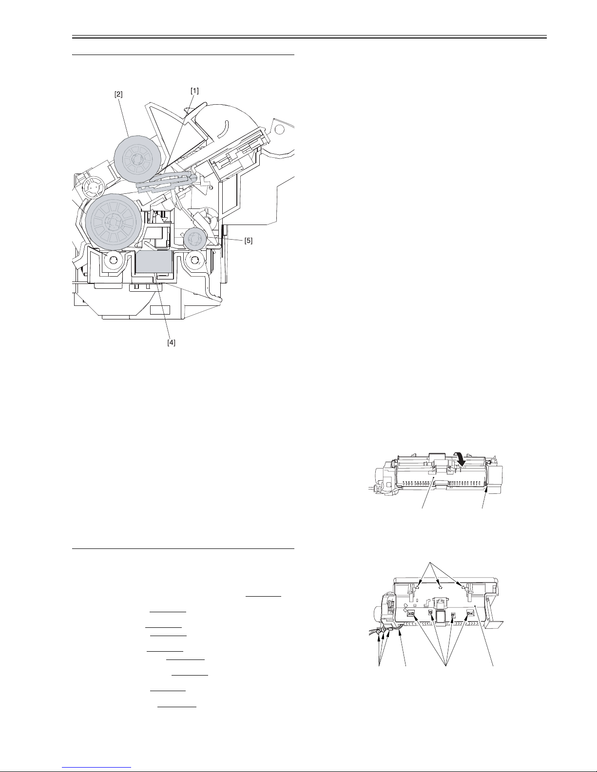
1) Free the claw [1], and detach the upper reader unit frame [2].
F-2-2
2) Free the harness [1] from the cable guide [2].
3) Remove the 7 screws [3], and detach the cover [4].
F-2-3
4) Free the 2 claws [1], and detach the Separation guide unit [2].
[1] Separation guide [4] Contact sensor
[2] Separation roller [5] Document delivery roller
[3] Document feed roller
[1][2]
[1][2] [3]
[3]
[4]
Chapter 2
2-2
F-2-4
2.2.2 Contact Sensor
2.2.2.1 Preparation for Removing the Contact Sensor
0018-4169
1) Remove the document feed tray and the paper tray cover. (page 7-2)Ref-
erence[Removing the Document Feed Tray and the Paper Tray Cover]
2) Detach the right cover. (page 7-2)
Reference[Detaching the Right Cov-
er]
3) Detach the left cover. (page 7-2)
Reference[Detaching the Left Cover]
4) Detach the front cover. (page 7-1)
Reference[Detaching the Front Cov-
er]
5) Detach the rear cover. (page 7-1)
Reference[Detaching the Rear Cover]
6) Detach the cartridge cover. (page 7-3)
Reference[Detaching the Car-
tridge Cover]
7) Remove the control panel unit. (page 7-4)
Rference[Removing the Con-
trol Panel Unit]
8) Detach the upper cover. (page 7-3)
Reference[Detaching the Upper Cov-
er]
9) Remove the reader unit. (page 2-5)
Reference[Removing the Reader
Unit]
2.2.2.2 Removing the Contact Sensor
0018-4170
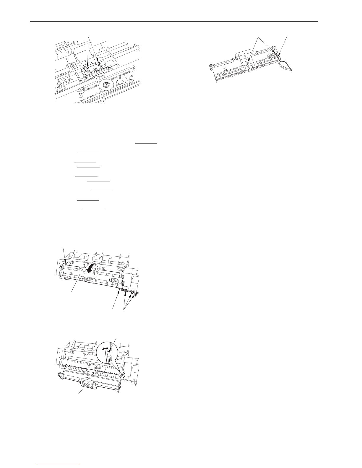
1) Free the harness [1] from the cable guide [2].
2) Open the lower reader unit frame [3], and free the claw [4].
F-2-5
3) Free the claw [1], and detach the lower reader unit frame [2].
F-2-6
4) Remove the 2 screws [1], and remove the grounding wire [2].
F-2-7
[1]
[2]
[1]
[2]
[3]
[4]
[1]
[2]
[1] [2]
Chapter 2
2-3
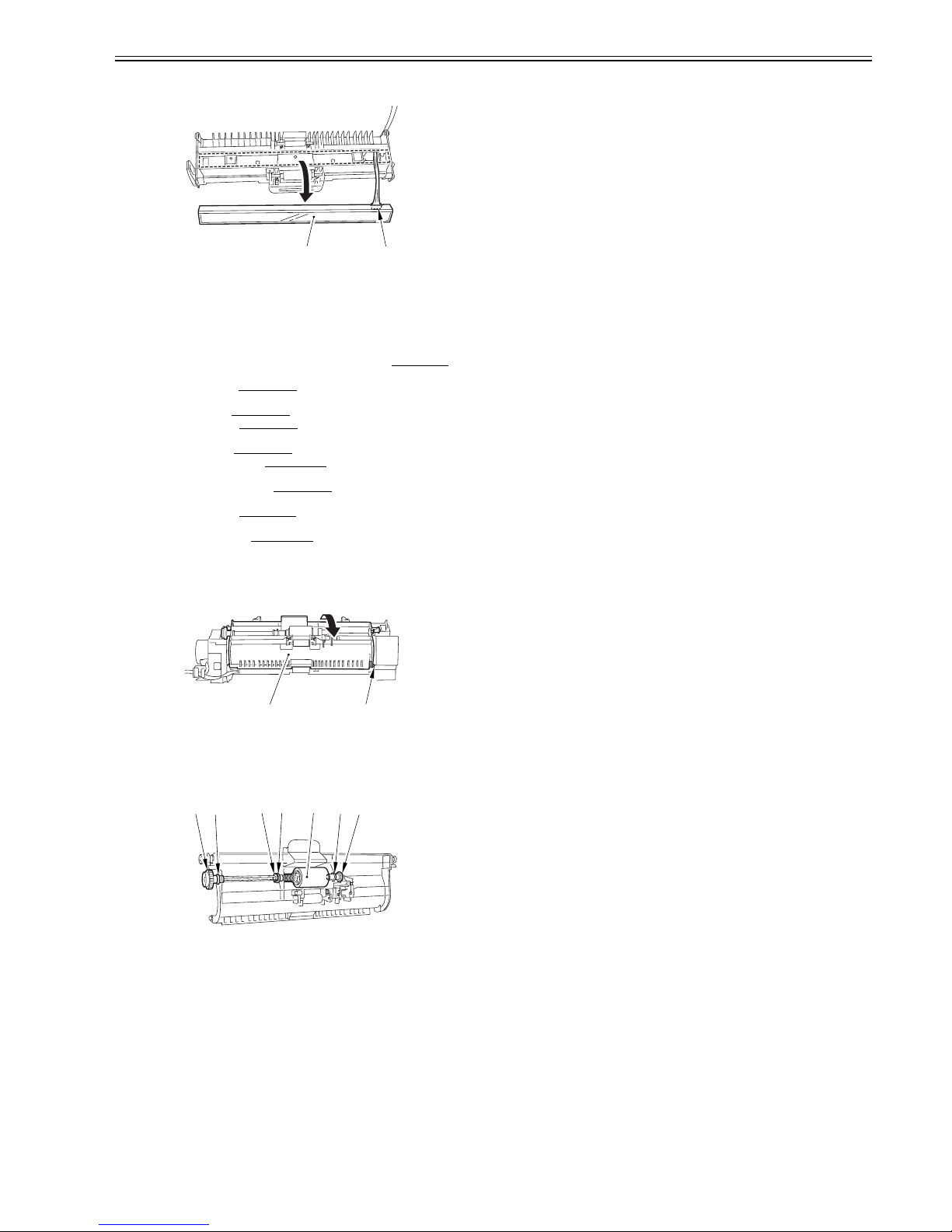
5) Detach the contact sensor [1] from the lower reader unit frame, and disconnect the connector [2].
F-2-8
2.2.3 Separation Roller
2.2.3.1 Preparation for Removing the Document
Separation Roller
0018-4171
1) Remove the document feed tray and the paper tray cover. (page 7-2)Reference[Removing the Document Feed Tray and the Paper Tray Cover]
2) Detach the right cover. (page 7-2)
Reference[Detaching the Right Cov-
er]
3) Detach the left cover. (page 7-2)
Reference[Detaching the Left Cover]
4) Detach the front cover. (page 7-1)
Reference[Detaching the Front Cov-
er]
5) Detach the rear cover. (page 7-1)
Reference[Detaching the Rear Cover]
6) Detach the cartridge cover. (page 7-3)
Reference[Detaching the Car-
tridge Cover]
7) Remove the control panel unit. (page 7-4)
Rference[Removing the Con-
trol Panel Unit]
8) Detach the upper cover. (page 7-3)
Reference[Detaching the Upper Cov-
er]
9) Remove the reader unit. (page 2-5)
Reference[Removing the Reader
Unit]
2.2.3.2 Removing the Document Separation Roller
0018-4172
1) Free the claw [1], and detach the upper reader unit frame [2].
F-2-9
2) While freeding the claw, detach the 2 gears [1].
3) Detach the 2 bushings [2].
4) Remove the E-ring [3], and detach the bushing [4].
5) Remove the separation roller [5] together with the shaft.
F-2-10
[1] [2]
[1][2]
[1]
[1]
[2]
[2]
[3] [4] [5]
Chapter 2
2-4
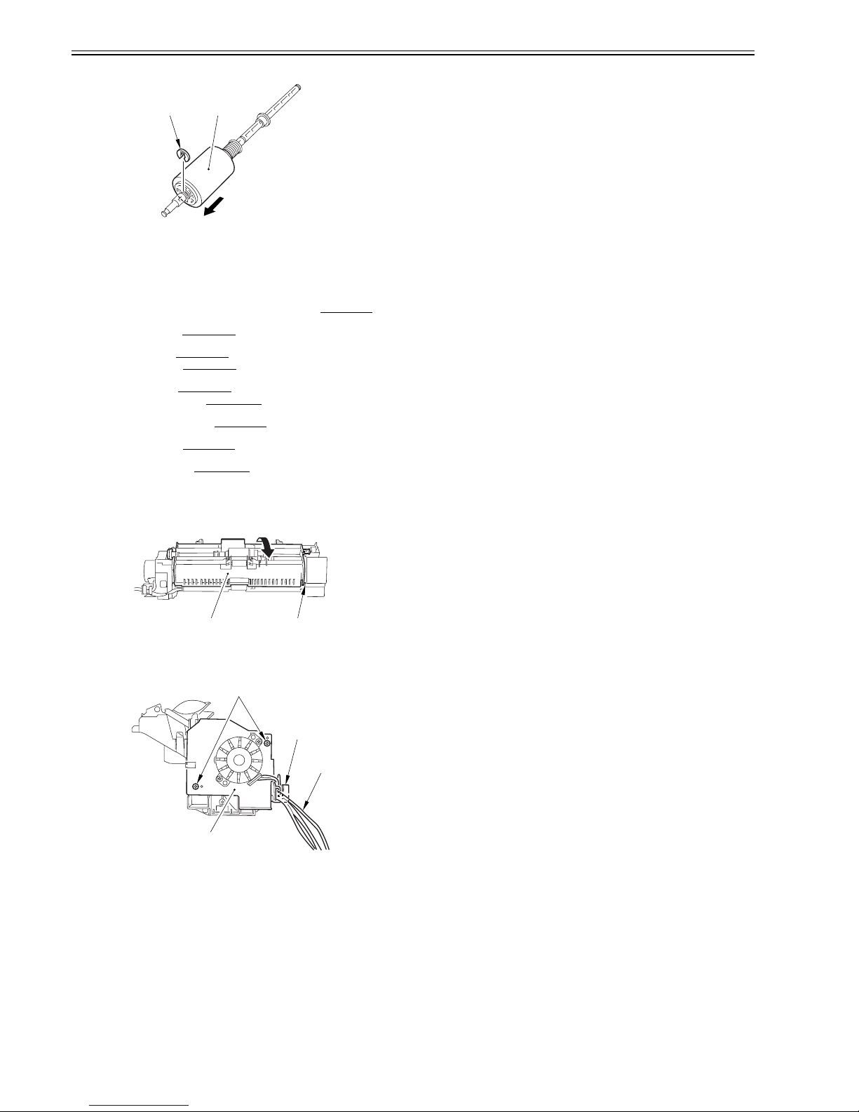
6) Remove the E-ring [1], and detach the separation roller [2] from the shaft.
F-2-11
2.2.4 Feed Roller
2.2.4.1 Preparation for Removing the Document Feed
Roller
0018-4173
1) Remove the document feed tray and the paper tray cover. (page 7-2)Ref-
erence[Removing the Document Feed Tray and the Paper Tray Cover]
2) Detach the right cover. (page 7-2)
Reference[Detaching the Right Cov-
er]
3) Detach the left cover. (page 7-2)
Reference[Detaching the Left Cover]
4) Detach the front cover. (page 7-1)
Reference[Detaching the Front Cov-
er]
5) Detach the rear cover. (page 7-1)
Reference[Detaching the Rear Cover]
6) Detach the cartridge cover. (page 7-3)
Reference[Detaching the Car-
tridge Cover]
7) Remove the control panel unit. (page 7-4)
Rference[Removing the Con-
trol Panel Unit]
8) Detach the upper cover. (page 7-3)
Reference[Detaching the Upper Cov-
er]
9) Remove the reader unit. (page 2-5)
Reference[Removing the Reader
Unit]
2.2.4.2 Removing the Document Feed Roller
0018-4174
1) Free the claw [1], and detach the upper reader unit frame [2].
F-2-12
2) Free the harness [1] from the cable guide [2].
3) Remove the 2 screws [3], and detach the side plate [4].
F-2-13
[1] [2]
[1][2]
[4]
[3]
[2]
[1]
 Loading...