

Canon i-SENSYS MF4340d, i-SENSYS MF4350d, i-SENSYS D450d, i-SENSYS MF4370dn, i-SENSYS MF4380dn Service Manual
...
Aug 22 2008
Service Manual
MF4300 Series


Application
This manual has been issued by Canon Inc. for qualified persons to learn technical theory, installa tion, ma intenance, and repair
of products. This manual covers all localities where the products are sold. For this reason, there may be information in this
manual that does not apply to your locality.
Corrections
This manual may contain technical inaccuracies or typographical errors due to improvements or changes in products. When
changes occur in applicable products or in the contents of this manual, Canon will release technical information as the need
arises. In the event of major changes in the contents of this manual over a long or short period, Canon will issue a new edition
of this manual.
The following paragraph does not apply to any countries where such provisions are inconsistent with local law.
Trademarks
The product names and company names used in this manual are the registered trademarks of the individual companies.
Copyright
This manual is copyrighted with all rights reserved. Under the copyright laws, this manual may not be copied, reproduced or
translated into another language, in whole or in part, without the written consent of Canon Inc.
COPYRIGHT © 2001 CANON INC.
Printed in Japan
Caution
Use of this manual should be strictly supervised to avoid disclosure of confidential information.

Introduction
Symbols Used
This documentation uses the following symbols to indicate special information:
Symbol Description
Indicates an item of a non-specific nature, possibly classified as Note, Caution, or Warning.
Indicates an item requiring care to avoid electric shocks.
Indicates an item requiring care to avoid combustion (fire).
Indicates an item prohibiting disassembly to avoid electric shocks or problems.
Indicates an item requiring disconnection of the power plug from the electric outlet.
Indicates an item intended to provide notes assisting the understanding of the topic in question.
Indicates an item of reference assisting the understanding of the topic in question.
Provides a description of a service mode.
Provides a description of the nature of an error indication.
Memo
REF.

Introduction
The following rules apply throughout this Service Manual:
1. Each chapter contains sections explaining the purpose of specific functions and the relationship between electrical and mechanical systems with reference to the timing of operation.
In the diagrams, represents the path of mechanical drive; where a signal name accompanies the symbol , the arrow indicates the
direction of the electric signal.
The expression "turn on the power" m eans flipping on the power switch, closing the front door, and closing the delivery unit door, which results in
supplying the machine with power.
2. In the digital circuits, '1'is used to indicate that the voltage level of a given signal is "High", while '0' is used to indicate "Low".(The voltage value, however, differs from circuit to circuit.) In addition, the asterisk (*) as in "DRMD*" indicates that the DRMD signal goes on when '0'.
In practically all cases, the internal mechanisms of a microprocessor cannot be checked in the fi eld. Therefore, the operations of the microprocessors
used in the machines are not discussed: they are explained in terms of from sensors to the input of the DC controller PCB and from the output of the
DC controller PCB to the loads.
The descriptions in this Service Manual are subject to change without notice for product improvement or other purposes, and major changes will be communicated in the form of Service Information bulletins.
All service persons are expected to have a good understanding of the contents of this Service Manual and all relevant Service Information bulletins and be
able to identify and isolate faults in the machine."


Contents
Contents
Chapter 1 Introduction
1.1 Product Specifications................................................................................................................................1- 1
1.1.1 Names of Parts.................................... .................................................. ....................................... ... ........................1- 1
1.1.1.1 External View........................................................................................................................................................................... 1- 1
1.1.1.2 Section View (Host Machine)................................................................................................................................................... 1- 4
1.1.1.3 Section View (ADF/DADF)....................................................................................................................................................... 1- 5
1.1.1.4 Control panel............................................................................................................................................................................1- 6
1.1.2 Safety ......................................................................................................................................................................1- 7
1.1.2.1 Safety of the Host Machine's Laser Mechanism......................................................................................................................1- 7
1.1.2.2 CDRH Regulations................................................................................................................................................................... 1- 7
1.1.2.3 Handling of the Laser Assembly .............................................................................................................................................. 1- 8
1.1.2.4 Safety of the Toner .................................................................................................................................................................. 1- 8
1.1.2.5 Fire Attention............................................................................................................................................................................1- 8
1.1.2.6 Points no Note when Replacing / Disposing the Lithium Battery.............................................................................................1- 8
1.1.3 Product Specifications.............................................................................................................................................1- 9
1.1.3.1 Host Machine Specifications.................................................................................................................................................... 1- 9
1.1.3.2 ADF/DADF Specifications...................................................................................................................................................... 1- 10
1.1.3.3 FAX Specifications................................................................................................................................................................. 1- 10
1.1.4 Function List............................ ... ................................................... .. ......................................................................1- 11
1.1.4.1 Scanning Range (ADF/DADF)...............................................................................................................................................1- 11
1.1.4.2 Scanning Range (copyboard) ................................................................................................................................................ 1- 11
1.1.4.3 Recording Range (Copy) ....................................................................................................................................................... 1- 12
1.1.4.4 Recording Range (Reception) ...............................................................................................................................................1- 13
1.1.4.5 Recording Range (Printer).....................................................................................................................................................1- 13
1.1.4.6 Operation Environment of the Printer Driver.......................................................................................................................... 1- 14
1.1.4.7 Network Specifications........................................................................................................................................................... 1- 14
Chapter 2 Basic Operation
2.1 Construction ...............................................................................................................................................2- 1
2.1.1 Function Configuration ............................................................................................................................................2- 1
2.2 Basic Sequence..........................................................................................................................................2- 1
2.2.1 Basic Operation Sequence............................................................................................................................... .......2- 1
Chapter 3 Original Exposure System
3.1 Basic Construction......................................................................................................................................3- 1
3.1.1 Specifications / Control / Function List ....................................................................................................................3- 1
3.1.2 Major Components.............................. .. ..................................................................................................................3- 1
3.2 Parts Replacement Procedure ...................................................................................................................3- 3
3.2.1 Scanner Unit............................................................................................................................ .. ..............................3- 3
3.2.1.1 Preparation for Removing the Scanner Unit ............................................................................................................................ 3- 3
3.2.1.2 Removing the Scanner Unit.....................................................................................................................................................3- 3
3.2.2 Reader Motor............................................... .................................................. ... .......................................................3- 3
3.2.2.1 Preparation for Removing the Flat Bed Motor .........................................................................................................................3- 3
3.2.2.2 Removing the Flat Bed Motor .................................................................................................................................................. 3- 3
3.2.3 Contact Sensor.................................... ....................................................................................................................3- 5
3.2.3.1 Removing the Contact Sensor.................................................................................................................................................3- 5
Chapter 4 Original Feeding System
4.1 Basic Operation..........................................................................................................................................4- 1
4.1.1 Basic Operation (ADF) ................................................. ... .................................................. ... ...................................4- 1

Contents
4.1.2 Basic Operation (DADF)..................... .......................................................................................... .. .........................4- 2
4.1.3 Original Detection ....................................................................................................................................................4- 4
4.2 Detection Jams........ ... ... ... .......................................... ... .... ... ... ... ................................................................4- 5
4.2.1 Jam Detection....................................................................................................................................... ... ................4- 5
4.3 ADF/DADF .................................................................................................................................................4- 6
4.3.1 Pick-up Roller................................... ... .................................................. ...................................................................4- 6
4.3.1.1 Removing the ADF Pickup Roller ............................................................................................................................................ 4- 6
4.3.1.2 Removing the DADF Pickup Roller Unit ..................................................................................................................................4- 6
4.3.2 ADF Motor................................ ... .................................................. ...........................................................................4- 8
4.3.2.1 Preparation for Removing the ADF/DADF Motor..................................................................................................................... 4- 8
4.3.2.2 Removing the ADF Motor ........................................................................................................................................................ 4- 8
4.3.2.3 Removing the DADF Motor......................................................................................................................................................4- 9
4.3.3 Separation Pad.................. ................................................... .................................................................................4- 12
4.3.3.1 Removing the ADF Separation Pad....................................................................................................................................... 4- 12
4.3.3.2 Removing the DADF Separation Pad .................................................................................................................................... 4- 12
Chapter 5 Laser Exposure
5.1 Overview/Configuration..............................................................................................................................5- 1
5.1.1 Overview..................................................................................................................................................................5- 1
5.2 Controlling the Laser Activation Timing......................................................................................................5- 2
5.2.1 Laser ON / OFF Control................................................................................................................................. .. ........5- 2
5.3 Controlling the Intensity of Laser Light.......................................................................................................5- 2
5.3.1 Auto Photoelectric Current Control (APC) ...............................................................................................................5- 2
5.4 Controlling the Laser Scanner Motor..........................................................................................................5- 4
5.4.1 Overview..................................................................................................................................................................5- 4
5.4.2 Scanner Motor Speed Control.................................................................................................................................5- 4
5.4.3 Detection of Fault of the Scanner Motor...................... ..................................................... ... ... .................................5- 4
5.5 Parts Replacement Procedure ...................................................................................................................5- 5
5.5.1 Laser/Scanner Unit..................................................................................................................................................5- 5
5.5.1.1 Preparation for Removing the Laser Scanner Unit .................................................................................................................. 5- 5
5.5.1.2 Removing the Laser Scanner Unit...........................................................................................................................................5- 5
Chapter 6 Image Formation
6.1 Overview/Configuration..............................................................................................................................6- 1
6.1.1 Configuration..................................................................................................................... ... ....................................6- 1
6.1.2 Print Process..................................................................................................................... ... ....................................6- 1
6.2 Driving and Controlling the High-Voltage System ......................................................................................6- 2
6.2.1 Generation of Transfer Charging Bias.................................................................................................. ...................6- 2
6.3 Toner Cartridge ..........................................................................................................................................6- 3
6.3.1 Toner Level Detection................................................................... ... ........................................................................6- 3
6.4 Parts Replacement Procedure ...................................................................................................................6- 4
6.4.1 Transfer Charging Roller.................................................................................................................................. ........6- 4
6.4.1.1 Removing the Transfer Charging Roller ..................................................................................................................................6- 4
Chapter 7 Pickup and Feed System
7.1 Overview/Configuration..............................................................................................................................7- 1
7.1.1 Overview..................................................................................................................................................................7- 1
7.2 Other Control................. ... ... .......................................... .... ... ......................................................................7- 2
7.2.1 Overview..................................................................................................................................................................7- 2
7.3 Detection Jams........ ... ... ... .......................................... ... .... ... ... ... ................................................................7- 3
7.3.1 Jam Detection Outline..................................................................................................................... .........................7- 3
7.3.1.1 Overview.................................................................................................................................................................................. 7- 3
7.3.2 Delay Jams......................................................................................................................................................... ... ..7- 3
7.3.2.1 Pickup Delay Jam .................................................................................................................................................................... 7- 3

Contents
7.3.2.2 Delivery Delay Jam.................................................................................................................................................................. 7- 3
7.3.3 Stationary Jams................................ ... .. ................................................... ...............................................................7- 3
7.3.3.1 Pickup Stationary Jam ............................................................................................................................................................. 7- 3
7.3.3.2 Delivery Stationary Jam...........................................................................................................................................................7- 3
7.3.4 Other Jams..............................................................................................................................................................7- 3
7.3.4.1 Door Open Jam........................................................................................................................................................................7- 3
7.3.4.2 Wrapping Jam.......................................................................................................................................................................... 7- 4
7.3.4.3 Residual Jam at Startup........................................................................................................................................................... 7- 5
7.4 Duplex Unit............................................... .... ... .......................................... ... ... ...........................................7- 6
7.4.1 Overview..................................................................................................................................................................7- 6
7.5 Parts Replacement Procedure ...................................................................................................................7- 7
7.5.1 Main Motor............................................................................................................................... ................................7- 7
7.5.1.1 Preparation for Removing Main Motor.....................................................................................................................................7- 7
7.5.1.2 Removing Main Motor.............................................................................................................................................................. 7- 7
7.5.2 Separation Pad........................................................................................................................................................7- 7
7.5.2.1 Preparation for Removing Separation Pad .............................................................................................................................. 7- 7
7.5.2.2 Removing Separation Pad....................................................................................................................................................... 7- 7
7.5.3 Pickup Roller .............................................................................................................................................. .............7- 7
7.5.3.1 Removing Pickup Roller........................................................................................................................................................... 7- 7
Chapter 8 Fixing System
8.1 Overview/Configuration ..............................................................................................................................8- 1
8.1.1 Specification/Control/Function List........................................................................................................... ...............8- 1
8.1.2 Overview..................................................................................................................................................................8- 1
8.2 Various Control Mechanisms......................................................................................................................8- 3
8.2.1 Controlling the Temperature of the Fixing Unit........................................................................................................8- 3
8.2.1.1 Fixing Temperature Control ..................................................................................................................................................... 8- 3
8.3 Protection Function.....................................................................................................................................8- 4
8.3.1 Protection Function................................................................................................................................... ...............8- 4
8.4 Parts Replacement Procedure ...................................................................................................................8- 6
8.4.1 Fixing Unit.............................................. ... ................................................... .. ........................................ ..................8- 6
8.4.1.1 Preparation for Removing Fixing Assembly............................................................................................................................. 8- 6
8.4.1.2 Removing Fixing Assembly......................................................................................................................................................8- 6
8.4.2 Fixing Film Unit........................................................................................................................................................8- 6
8.4.2.1 Preparation for Removing Fixing Film Unit .............................................................................................................................. 8- 6
8.4.2.2 Removing Fixing Film Unit.......................................................................................................................................................8- 7
Chapter 9 External and Controls
9.1 Control Panel..............................................................................................................................................9- 1
9.1.1 Outline................................................................................................................................................................. ... .9- 1
9.2 Power Supply .............................................................................................................................................9- 1
9.2.1 Power Supply .................................................... .. ................................................... ... ....................................... ... ....9- 1
9.2.1.1 Power Supply Route ................................................................................................................................................................ 9- 1
9.2.2 Protection Function................................................................................................................................... ...............9- 1
9.2.2.1 Protecting Function.................................................................................................................................................................. 9- 1
9.3 Parts Replacement Procedure ...................................................................................................................9- 2
9.3.1 Front Cover................................................................................................................................... ...........................9- 2
9.3.1.1 Removing the Front Cover....................................................................................................................................................... 9- 2
9.3.2 Rear Cover..............................................................................................................................................................9- 2
9.3.2.1 Preparation for Removing the Rear Cover...............................................................................................................................9- 2
9.3.2.2 Removing the Rear Cover ....................................................................................................................................................... 9- 2
9.3.3 Right Cover................................................................................................................................... ...........................9- 2
9.3.3.1 Removing the Right Cover....................................................................................................................................................... 9- 2
9.3.4 Left Cover................................................................................................................................................. ...............9- 3
9.3.4.1 Removing the Left Cover ......................................................................................................................................................... 9- 3
9.3.5 Upper Cover............................................................................................................................................................9- 4

Contents
9.3.5.1 Preparation for Removing the Upper Cover............................................................................................................................. 9- 4
9.3.5.2 Removing the Upper Cover ..................................................................................................................................................... 9- 4
9.3.6 Cartridge Cover.......................................................................................................................... ..............................9- 4
9.3.6.1 Preparation for Removing the Printer Cover............................................................................................................................ 9- 4
9.3.6.2 Removing the Printer Cover..................................................................................................................................................... 9- 4
9.3.7 Operation Panel Unit....................................................................................................................... ... ......................9- 4
9.3.7.1 Removing the Control Panel Unit.............................................................................................................................................9- 4
9.3.8 SCNT Board...................................................................................................................... .......................................9- 5
9.3.8.1 Preparation for Removing the SCNT PCB............................................................................................................................... 9- 5
9.3.8.2 Removing the SCNT PCB........................................................................................................................................................ 9- 5
9.3.8.3 Actions At Replacing the SCNT PCB....................................................................................................................................... 9- 5
9.3.9 DCNT Board ................................................................................................................................ ............................9- 6
9.3.9.1 Preparation for Removing the DCNT PCB............................................................................................................................... 9- 6
9.3.9.2 Removing the DCNT PCB ....................................................................................................................................................... 9- 6
9.3.10 Power Supply PCB....................................... ... ....................................................................................... ... .............9- 7
9.3.10.1 Preparation for Removing the Power Supply PCB................................................................................................................. 9- 7
9.3.10.2 Removing the Power Supply PCB ......................................................................................................................................... 9- 7
9.3.11 High-voltage Power Supply Board.........................................................................................................................9- 7
9.3.11.1 Preparation for Removing the High Voltage PCB..................................................................................................................9- 7
9.3.11.2 Removing the High Voltage PCB........................................................................................................................................... 9- 8
Chapter 10 Maintenance and Inspection
10.1 Periodically Replaced Parts....................................................................................................................10- 1
10.1.1 Periodically Replaced Parts.................................................................................................................................10- 1
10.2 Periodical Service........... ... .... ... ... ... .... ... .......................................... ... ... .... ... ... .......................................10- 1
10.2.1 Periodically Service Items....................................................................................................................................10- 1
10.3 Cleaning .................................................................................................................................................10- 1
10.3.1 Cleaning Items.....................................................................................................................................................10- 1
10.3.2 Cleaning Method (External Covers). ....................................................................................................................10- 1
10.3.3 Cleaning Method (Reader Unit) ...........................................................................................................................10- 2
10.3.4 Cleaning Method (Pressure Roller)........................................................................................................... ... ........10- 3
Chapter 11 Measurement and Adjustments
11.1 Basic Adjustments.............................................. ... ... ... .... .......................................... ... ... .......................11- 1
11.1.1 Paper Margin Adjustment.....................................................................................................................................11- 1
11.1.2 Reading Adjustment.............................................................................................................................................11- 1
11.1.3 Print Adjustment...................................................................................................................................................11- 2
Chapter 12 Correcting Faulty Images
12.1 Outline of Electrical Components ...........................................................................................................12- 1
12.1.1 Clutch/Solenoid/Motor/Fan...................................................................................................................................12- 1
12.1.1.1 List of Solenoids/Motors....................................................................................................................................................... 12- 1
12.1.2 Sensor................................................................................................................................................. ... ..............12- 3
12.1.2.1 List of Sensors .....................................................................................................................................................................12- 3
12.1.3 PCBs....................................................................................................................................................................12- 5
12.1.3.1 List of PCBs .........................................................................................................................................................................12- 5
Chapter 13 Error Code
13.1 Error Code.............................................................................................................................................. 13- 1
13.1.1 Error Code Outline...............................................................................................................................................13- 1
13.1.2 Error Code................................................................................................................................ ... .. .......................13- 1
Chapter 14 Service Mode

Contents
14.1 Outline ....................................................................................................................................................14- 1
14.1.1 Setting Service Data........................................................ ... .................................................................................14- 1
14.1.2 How to Activate Service Mode.............................................................................................................................14- 1
14.1.3 Service Data Menu......................... ... .................................................. ... .............................................................14- 2
14.2 Service Soft Switch Settings (SSSW).....................................................................................................14- 4
14.2.1 Outline ........................................................................................................................................... ... ... ................14- 4
14.2.1.1 SOFT SWITCH Explained.............................................................................................. ...................................................... 14- 4
14.2.2 SSSW-SW02:......................................................................................................................................................14- 6
14.2.2.1 Function List......................................................................................................................................................................... 14- 6
14.2.2.2 Bit 2 and 3 Elaborated..........................................................................................................................................................14- 6
14.2.2.3 Bit 5 Elaborated....................................................................................................................................................................14- 6
14.2.3 SSSW-SW04.......................................................................................................................................................14- 6
14.2.3.1 Function List......................................................................................................................................................................... 14- 6
14.2.3.2 Bit 8 Elaborated....................................................................................................................................................................14- 7
14.2.4 SSSW-SW10.......................................................................................................................................................14- 7
14.2.4.1 Function List......................................................................................................................................................................... 14- 7
14.2.4.2 Bit 1 Elaborated....................................................................................................................................................................14- 8
14.2.4.3 Bit 2 Elaborated....................................................................................................................................................................14- 8
14.2.5 SSSW-SW16.......................................................................................................................................................14- 8
14.2.5.1 Function List......................................................................................................................................................................... 14- 8
14.2.6 SSSW-SW20.......................................................................................................................................................14- 8
14.2.6.1 ã@î\àÍóó............................................................................................................................................................................... 14- 8
14.2.6.2 Bit6ÅA7ÅA8ÇÃè⁄çÞ.............................................................................................................................................................. 14- 8
14.2.7 SSSW-SW21.......................................................................................................................................................14- 9
14.2.7.1 Function List......................................................................................................................................................................... 14- 9
14.2.7.2 Bit 4 Elaborated....................................................................................................................................................................14- 9
14.2.8 SSSW-SW23.......................................................................................................................................................14- 9
14.2.8.1 ã@î\àÍóó............................................................................................................................................................................... 14- 9
14.2.8.2 Bit5ÅA6ÇÃè⁄çÞ .................................................................................................................................................................. 14- 10
14.2.8.3 Bit7ÅA8ÇÃè⁄çÞ .................................................................................................................................................................. 14- 10
14.2.9 SSSW-SW30.....................................................................................................................................................14- 10
14.2.9.1 Function List....................................................................................................................................................................... 14- 10
14.2.9.2 Bit 7 and 8 Elaborated........................................................................................................................................................14- 11
14.2.10 SSSW-SW37 ...................................................................................................................................................14- 11
14.2.10.1 Function List.....................................................................................................................................................................14- 11
14.2.10.2 Bit 1 to Bit 6 Elaborated.................................................................................................................................................... 14- 11
14.2.11 SSSW-SW39 ...................................................................................................................................................14- 12
14.2.11.1 Function List.....................................................................................................................................................................14- 12
14.2.11.2 Bit 7 Elaborated................................................................................................................................................................ 14- 12
14.2.11.3 Bit 8 Elaborated................................................................................................................................................................ 14- 13
14.2.12 SSSW-SW51 ...................................................................................................................................................14- 13
14.2.12.1 Function List.....................................................................................................................................................................14- 13
14.2.12.2 Bit 3 and 4 Elaborated......................................................................................................................................................14- 13
14.2.13 SSSW-SW54 ...................................................................................................................................................14- 13
14.2.13.1 Function List.....................................................................................................................................................................14- 13
14.2.13.2 Bit 6 and 7 Elaborated......................................................................................................................................................14- 14
14.3 Test Mode (TEST) ................................................................................................................................14- 15
14.3.1 Overview............................................................................................................................................................14- 15
14.3.1.1 Outline of test mode...........................................................................................................................................................14- 15
14.3.1.2 Test mode menu ................................................................................................................................................................ 14- 15
14.3.2 Faculty Test.......................................................................................................................................................14- 16
14.3.2.1 Print test pattern................................................................................................................................................................. 14- 16
14.3.2.2 êMçÜÉeÉXÉg .................................................................................................................................................................... 14- 16
14.3.2.3 Sensor test.........................................................................................................................................................................14- 16
14.3.2.4 Key test .............................................................................................................................................................................. 14- 16
Chapter 15 Service Tools
15.1 Service Tools........................................................................................ ... ... ... .........................................15- 1

Contents
15.1.1 Solvents / Lubricants Table.............................................................................................................. ... ... ..............15- 1

Chapter 1 Introduction


Contents
Contents
1.1 Product Specifications....................................................................................................................................................1-1
1.1.1 Names of Parts ............................................................................................................................................................................. 1-1
1.1.1.1 External View..................................................................................................................................................................................................1-1
1.1.1.2 Section View (Host Machine)................................................... ......................................... .............................................................................1-4
1.1.1.3 Section View (ADF/DADF) ............... .... ... ......................................... ... .........................................................................................................1-5
1.1.1.4 Control panel...................................................................................................................................................................................................1-6
1.1.2 Safety ........................................................................................................................................................................................... 1-7
1.1.2.1 Safety of the Host Machine's Laser Mechanism. ... .... ......................................... ... ... ......................................................................................1-7
1.1.2.2 CDRH Regulations..........................................................................................................................................................................................1-7
1.1.2.3 Handling of the Laser Assembly.....................................................................................................................................................................1-8
1.1.2.4 Safety of the Toner..........................................................................................................................................................................................1-8
1.1.2.5 Fire Attention ..................................................................................................................................................................................................1-8
1.1.2.6 Points no Note when Replacing / Disposing the Lithium Battery ..................................................................................................................1-8
1.1.3 Product Specifications ................................................................................................................................................................. 1-9
1.1.3.1 Host Machine Specifications...........................................................................................................................................................................1-9
1.1.3.2 ADF/DADF Specifications ...........................................................................................................................................................................1-10
1.1.3.3 FAX Specifications .......................................................................................................................................................................................1-10
1.1.4 Function List .............................................................................................................................................................................. 1-11
1.1.4.1 Scanning Range (ADF/DADF)........ ... .... ......................................... ... ..........................................................................................................1-11
1.1.4.2 Scanning Range (copyboard) ........................................ ... ... ..........................................................................................................................1-11
1.1.4.3 Recording Range (Copy)...............................................................................................................................................................................1-12
1.1.4.4 Recording Range (Reception) .......................................................................................................................................................................1-13
1.1.4.5 Recording Range (Printer) ............................................................................................................................................................................1-13
1.1.4.6 Operation Environment of the Printer Driver ...............................................................................................................................................1-14
1.1.4.7 Network Specifications .................................................................................................................................................................................1-14

Chapter 1
1-1
1.1 Product Specifications
1.1.1 Names of Parts
1.1.1.1 External View
0020-2535
i-SENSYS MF4300dn / i-SENSYS MF4350d / i-SENSYS MF4380dn / i-SENSYS MF4310/4318 / i-SENSYS MF4320d / i-SENSYS MF4330d / i-SENSYS
MF4340d / i-SENSYS D450d / i-SENSYS MF4370dn
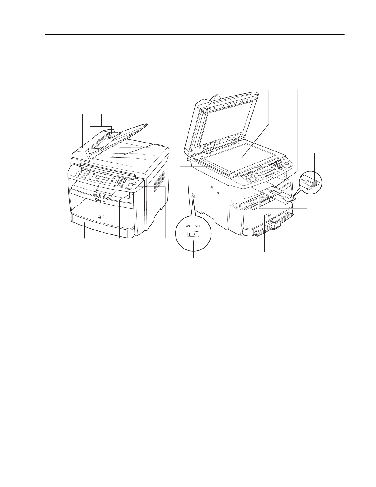
Front View (Body)(In the case of ADF)
F-1-1
T-1-1
[1] ADF (Automatic Document Feeder) [10] Platen glass
[2] Slide Guides [11] Output tray extension
[3] Document feeder tray [12] Paper stopper
[4] Document delivery tray [13] Slide guides for multi-purpose tray
[5] Operation panel [14] Paper guide rail
[6] USB memory port [15] Dust cover
[7] Output tray [16] Multi-purpose tray
[8] Paper cassette [17] Main power switch
[9] Scanning area
[1] [2] [3] [4]
[8] [7] [6] [5]
[9] [10] [11]
[12]
[13]
[14][15][16]
[17]
Chapter 1
1-2
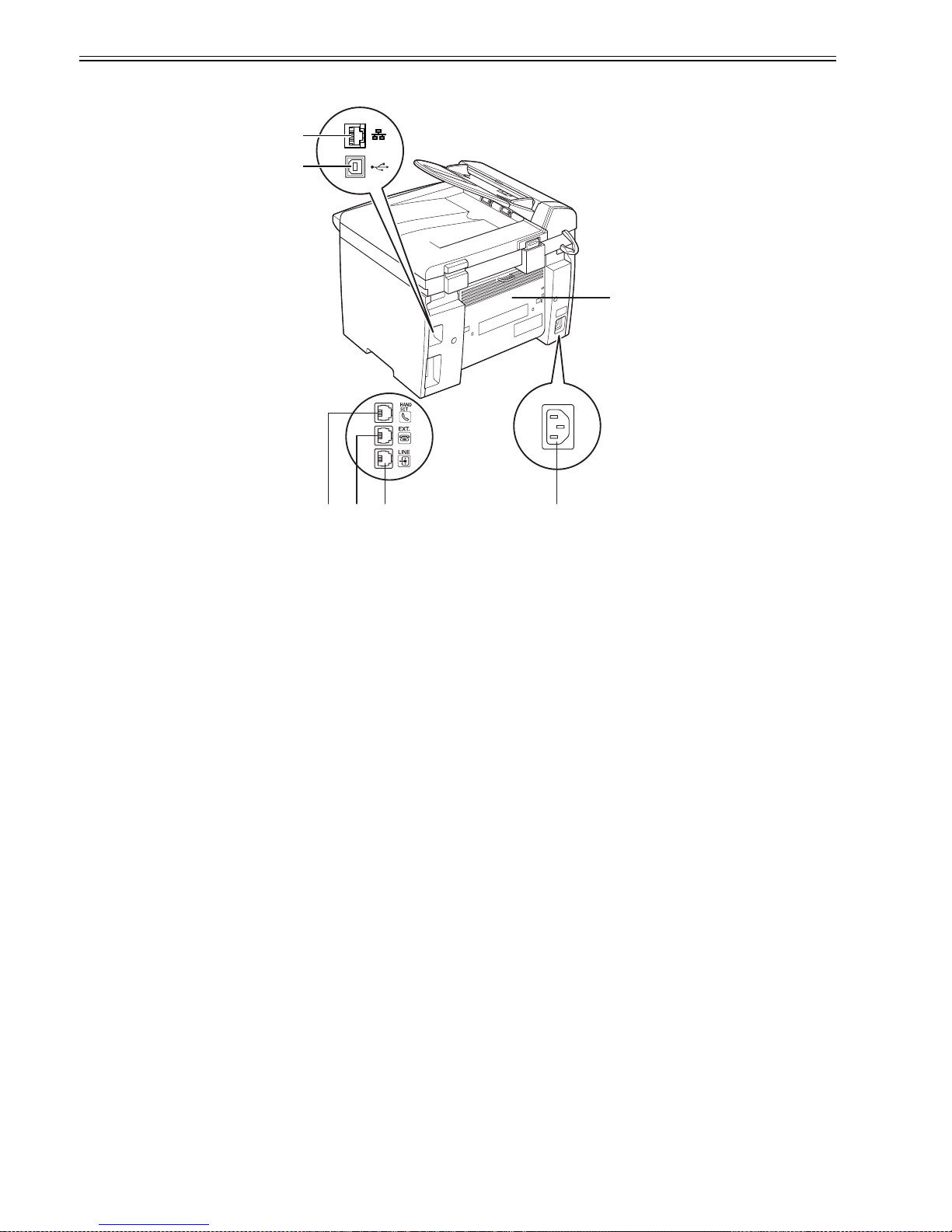
Rear View (Body)(In the case of ADF)
F-1-2
T-1-2
Front View (Body)(In the case of DADF)
[1] USB port [5] External device jack
[2] Rear cover [6] Handset jack
[3] Power socket [7] Ethernet port
[4] Telephone line jack
[1]
[2]
[4][5][6] [3]
[7]
Chapter 1
1-3
F-1-3
T-1-3
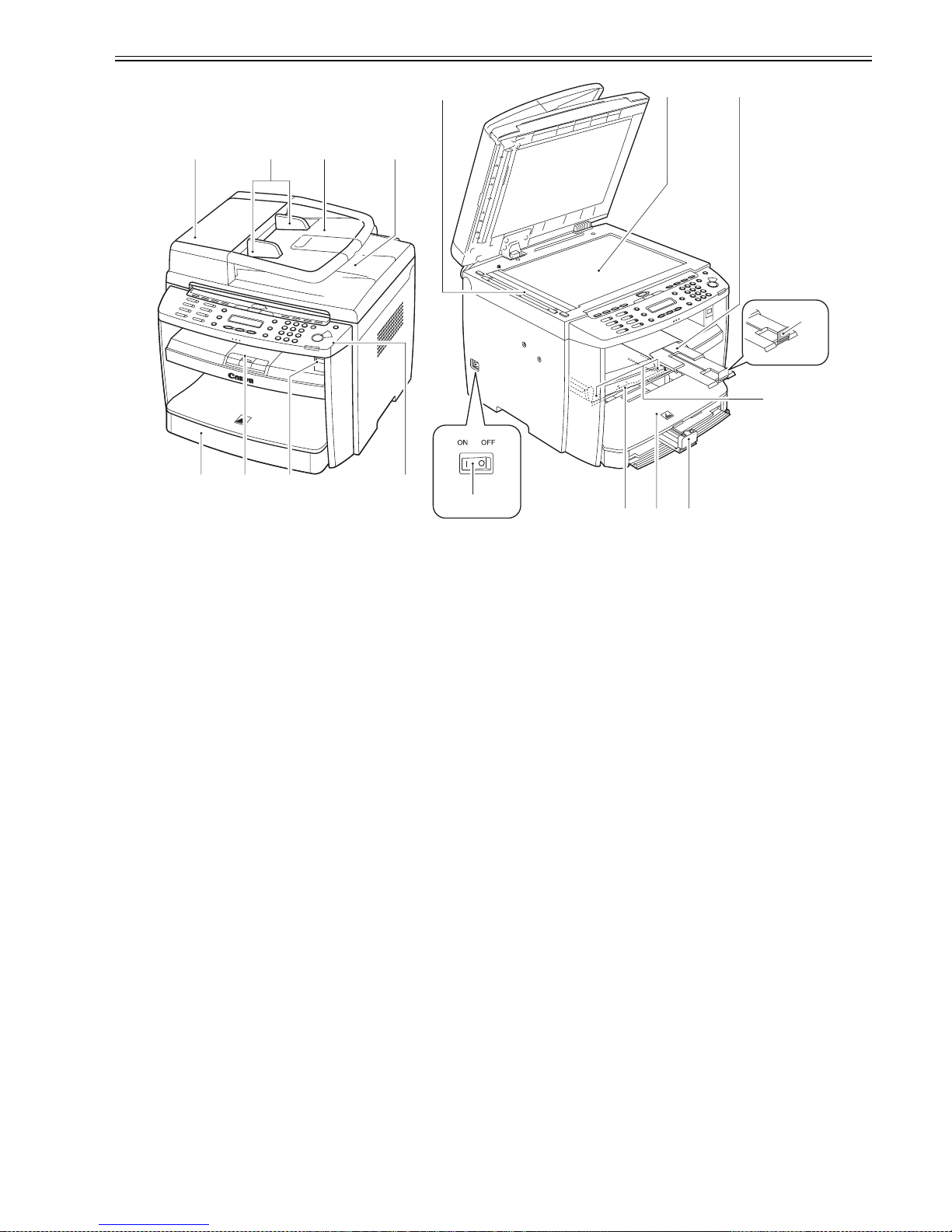
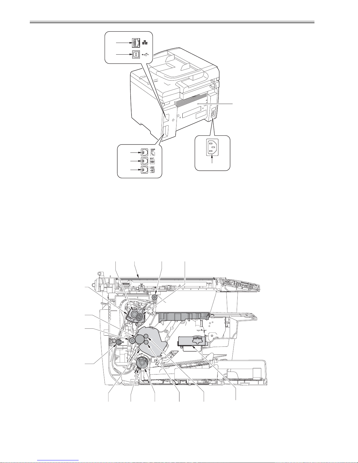
Rear View (Body)(In the case of DADF)
[1] DADF (Duplex Automatic Document Feeder) [10] Platen glass
[2] Slide Guides [11] Output tray extension
[3] Document feeder tray [12] Paper stopper
[4] Document delivery tray [13] Slide guides for multi-purpose tray
[5] Operation panel [14] Paper guide rail
[6] USB memory port [15] Dust cover
[7] Output tray [16] Multi-purpose tray
[8] Paper cassette [17] Main power switch
[9] DADF Scanning area
[1] [2] [3] [4]
[8] [7] [6] [5]
[9] [10] [11]
[12]
[14][15][16]
[17]
[13]
Chapter 1
1-4
F-1-4
T-1-4
1.1.1.2 Section View (Host Machine)
0020-2546
i-SENSYS MF4300dn / i-SENSYS MF4350d / i-SENSYS MF4380dn / i-SENSYS MF4310/4318 / i-SENSYS MF4320d / i-SENSYS MF4330d / i-SENSYS
MF4340d / i-SENSYS D450d / i-SENSYS MF4370dn
F-1-5
[1] USB port [5] External device jack
[2] Rear cover [6] Handset jack
[3] Power socket [7] Ethernet port
[4] Telephone line jack
[1] pressure roller [8] pick-up roller
[2] copyboard glass (scanning glass) [9] separation pad
[1]
[7]
[6]
[5]
[4]
[3]
[2]
[1] [2] [3] [4]
[6][7][8][9]
[11]
[12]
[10]
[13]
[14]
[5]
Chapter 1
1-5
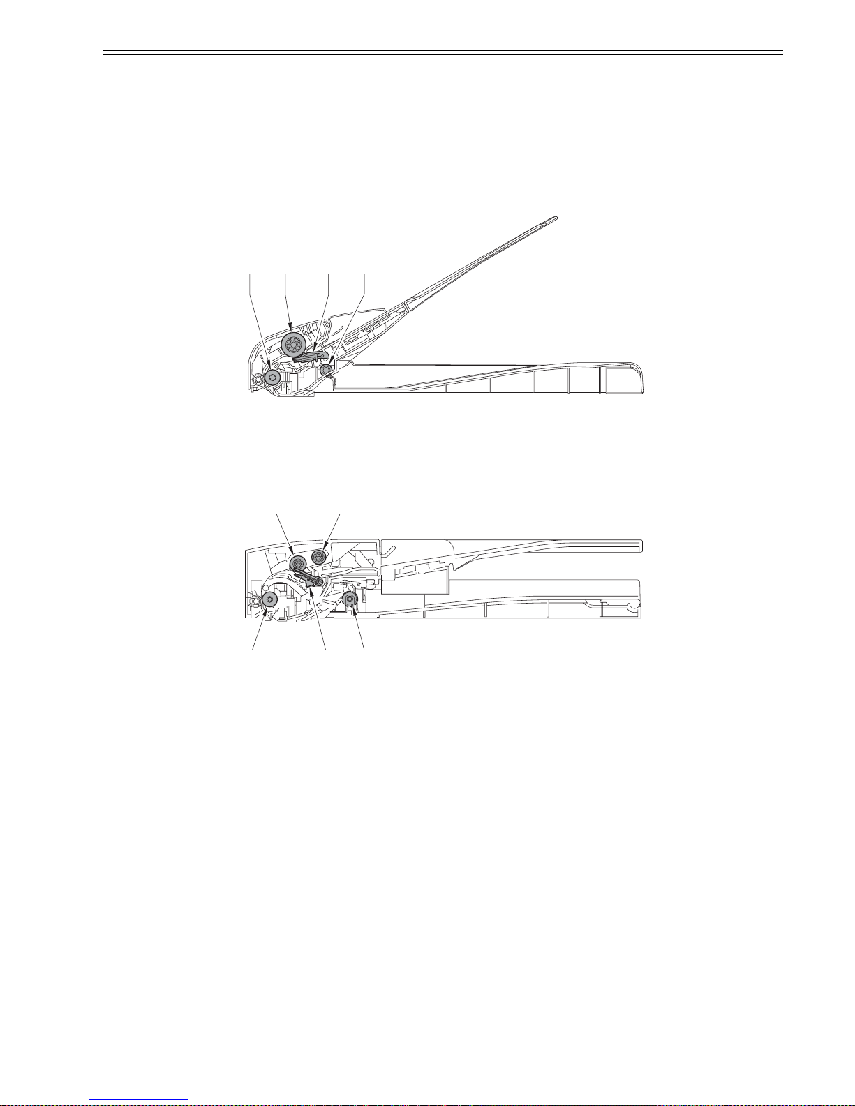
1.1.1.3 Section View (ADF/DADF)
0020-2548
i-SENSYS MF4300dn / i-SENSYS MF4350d / i-SENSYS MF4380dn / i-SENSYS MF4310/4318 / i-SENSYS MF4320d / i-SENSYS MF4330d / i-SENSYS
MF4340d / i-SENSYS D450d / i-SENSYS MF4370dn
ADF Section view
F-1-6
[1] registration roller
[2] pickup roller
[3] separation pad
[4] delivery roller
DADF Section View
F-1-7
[1] registration roller
[2] separation roller
[3] pickup roller
[4] separation pad
[5] delivery roller
[3] delivery roller [10] cartridge
[4] fixing film unit [11] duplexing feeding roller
[5] laser scanner unit [12] transfer charging roller
[6] primary charging roller [13] photosensitive drum
[7] developing cylinder [14] fixing unit
[1] [2] [3] [4]
[1]
[2] [3]
[4][5]

Chapter 1
1-6
1.1.1.4 Control panel
0020-2549
i-SENSYS MF4300dn / i-SENSYS MF4350d / i-SENSYS MF4380dn / i-SENSYS MF4310/4318 / i-SENSYS MF4320d / i-SENSYS MF4330d / i-SENSYS
MF4340d / i-SENSYS D450d / i-SENSYS MF4370dn
F-1-8
T-1-5
[1] [System Monitor] key [13] [Stop/Reset] key
[2] [View Settings] key [14] Error indicator
[3] [COPY] key [15] Processing/Data indicator
[4] [SEND/FAX] key [16] [Start] key
[5] [SCAN] key [17] Numeric key
[6] [Additional Functions] key [18] [Tone] key
[7] [2-Sided] key [19] [Clear] key
[8] [Enlarge/Reduce] key [20] [+] key
[9] [Density] key [21] [OK] key
[10] [Image Quality] key [22] [-] key
[11] [Collate/2 on 1] key [23] LCD display
[12] [Energy Saver] key key [24] [Toner Gauge] key
[1] [2] [3] [4] [5] [6] [7] [8] [9] [10] [11] [12]
[13][14][15][16][17][18][19][20][21][21][24]
[23]
COPY FAX SCAN

Chapter 1
1-7
F-1-9
T-1-6
1.1.2 Safety
1.1.2.1 Safety of the Host Machine's Laser Mechanism
0020-2550
i-SENSYS MF4300dn / i-SENSYS MF4350d / i-SENSYS MF4380dn / i-SENSYS MF4310/4318 / i-SENSYS MF4320d / i-SENSYS MF4330d / i-SENSYS
MF4340d / i-SENSYS D450d / i-SENSYS MF4370dn
Laser radiation can prove to be harmful to the human body. The host machine's laser scanning system is completely sealed by means of a protective housing and
external covers so that its light will not leak outside the host machine as long as the host machine is used normally.
1.1.2.2 CDRH Regulations
0020-2551
i-SENSYS MF4300dn / i-SENSYS MF4350d / i-SENSYS MF4380dn / i-SENSYS MF4310/4318 / i-SENSYS MF4320d / i-SENSYS MF4330d / i-SENSYS
MF4340d / i-SENSYS D450d / i-SENSYS MF4370dn
The Center for Devices and Radiological Health (CDRH) of the US Food and Drug Administrator put into forth regulations that relate to laser products on August
2nd, 1976.
These regulations apply to laser products produced on and after Aug ust 1st, 1976, and prohibit the sale of laser products without certification.
The following labels certify compliance with the CDRH regulations, and must be attached to all laser products that are sold in the US.
F-1-10
[1] [Hook] key [4] [Address Book] key
[2] [Recall/Pause] key [5] R key
[3] [Coded Dial] key [6] One-Touch Speed Dial keys
[1] [2] [3] [4]
[5][6]
CANON
30-2, SHIMOMARUKO, 3-CHOME, OHTAKU, TOKYO,
146, JAPAN.
MANUFACTURED:
THIS PRODUCT CONFORMS WITH DHHS RADIATION
PERFORMANCE STANDARD 21CFR CHAPTER 1
SUBCHAPTER J.
Chapter 1
1-8
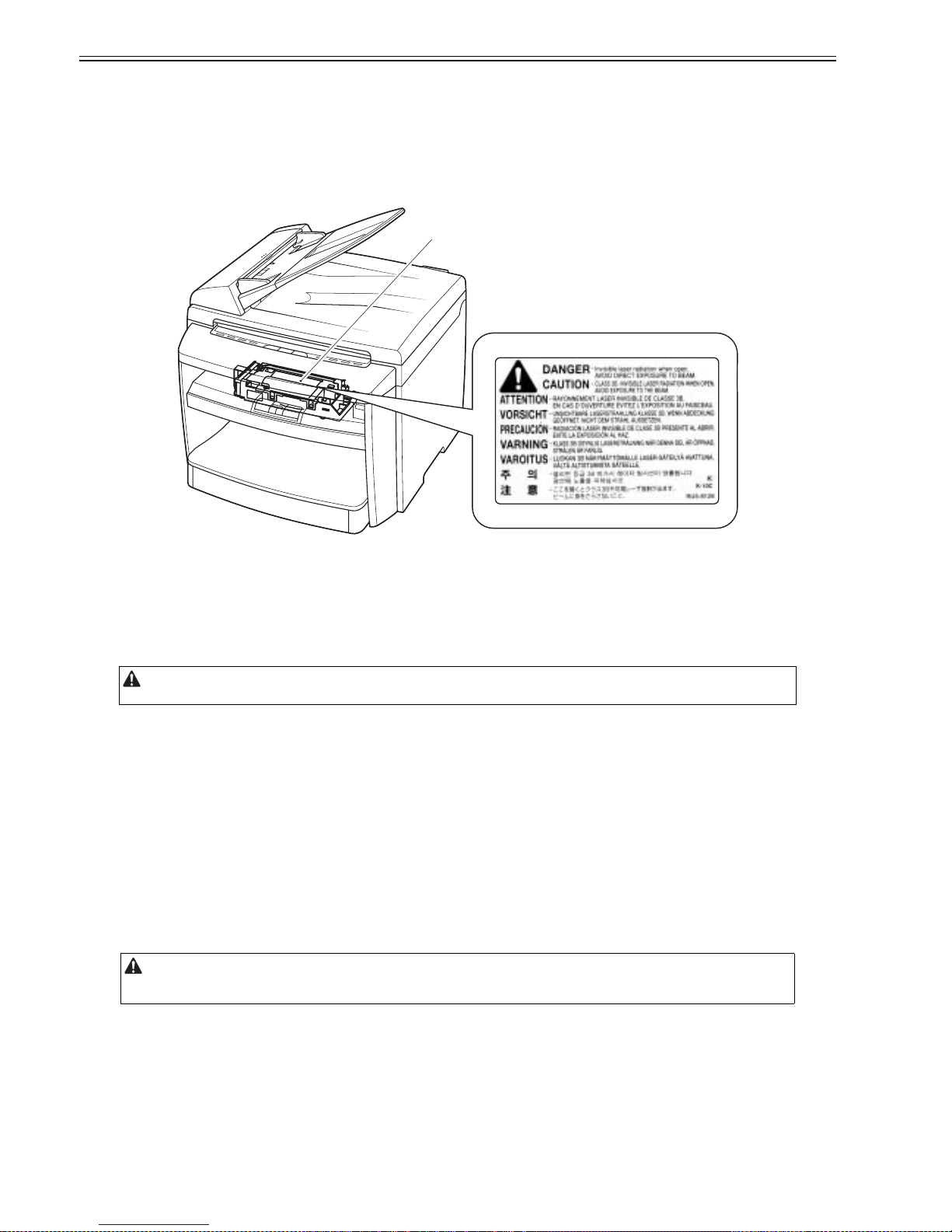
1.1.2.3 Handling of the Laser Assembly
0020-2552
i-SENSYS MF4300dn / i-SENSYS MF4350d / i-SENSYS MF4380dn / i-SENSYS MF4310/4318 / i-SENSYS MF4320d / i-SENSYS MF4330d / i-SENSYS
MF4340d / i-SENSYS D450d / i-SENSYS MF4370dn
When performing servicing work around the laser scanner unit of this machine, be sure not to insert a highly reflective tool such as a driver directly into the laser
light path. Also be sure to take off a watch or ring, etc. during servicing work. (Otherwise, the reflected laser beam may enter the eye.) The color of the laser light
for this machine is red. The labels [1] and [2] shown in the figure below are attached on the covers where the laser light may be reflected. Further, no adjustment
can be made to the laser scanner unit of this machine in the field.
The label [1] shown in the figure below is attached on the cover of the laser scanner assembly.
F-1-11
1.1.2.4 Safety of the Toner
0020-2553
i-SENSYS MF4300dn / i-SENSYS MF4350d / i-SENSYS MF4380dn / i-SENSYS MF4310/4318 / i-SENSYS MF4320d / i-SENSYS MF4330d / i-SENSYS
MF4340d / i-SENSYS D450d / i-SENSYS MF4370dn
Toner in General
Toner is a non-toxic material made up of plastic, iron, and small amounts of dye.
How to handle the toner adhered
1. When toner is adhered to the skin or clothing, wipe it off the skin or clothing by a dry tissue and wash the skin or clothing with water.
2. If you use hot water, toner is turned into gel and soaks into clothing. Under such a condition, toner cannot be removed.
3. Do not make toner come into contact with a vinyl material because they tend to react with each other.
1.1.2.5 Fire Attention
0020-2554
i-SENSYS MF4300dn / i-SENSYS MF4350d / i-SENSYS MF4380dn / i-SENSYS MF4310/4318 / i-SENSYS MF4320d / i-SENSYS MF4330d / i-SENSYS
MF4340d / i-SENSYS D450d / i-SENSYS MF4370dn
It is dangerous to throw the parts that include combustible materials such as lithium battery and toner cartridge etc., into fire. Any used battery must always be
disposed according to the appropriate local regulations.
1.1.2.6 Points no Note when Replacing / Disposing the Lithium Battery
0020-2555
i-SENSYS MF4300dn / i-SENSYS MF4350d / i-SENSYS MF4380dn / i-SENSYS MF4310/4318 / i-SENSYS MF4320d / i-SENSYS MF4330d / i-SENSYS
MF4340d / i-SENSYS D450d / i-SENSYS MF4370dn
Be sure not to throw toner into the fire. Doing so may cause an explosion.
There is a risk of explosion if the battery is replaced with an incorrect type.
Be sure to discard the used battery following the instruction in the manual.
[1]

Chapter 1
1-9
1.1.3 Product Specifications
1.1.3.1 Host Machine Specifications
0020-2556
i-SENSYS MF4300dn / i-SENSYS MF4350d / i-SENSYS MF4380dn / i-SENSYS MF4310/4318 / i-SENSYS MF4320d / i-SENSYS MF4330d / i-SENSYS
MF4340d / i-SENSYS D450d / i-SENSYS MF4370dn
Copyboard Fixed
Body Desktop (ADF standard type:MF4130/MF4150 only)
Light source type LED
Image reading method Contact Sensor Reading Method
Photosensitive medium OPD drum
Reproduction method Indirect electrostatic copying method
Exposure method Semiconductor laser
Charging method Roller contact charging method
Development method Dry system - element jumping development method
Transfer method Roller transfer method
Separation method Electrostatic separation (neutralizing needle) and curvature separation
Pickup method Cassette pick-up: 1 cassette
Manual feeding pick-up
Cassette pickup method Pad separation method
Multifeeder pickup method Pad separation method
Drum cleaning method Rubber blade
Fixing method On-demand fixing
Toner supply type By drum style toner cartridge
Toner type Magnetic negative toner
Toner save mode Yes
Original type Sheets, books, solids (up to 2 kg)
Maximum original size Fixed: 216mm x 297mm
ADF: 216mm x 356mm
Reproduction ratio 1 to 1 + / - 1.0 %, 1 to 2.00, 1 to 1.29, 1 to 0.78, 1 to 0.64, 1 to 0.50
Zoom: 0.50 to 2.00 (specified by the percent)
Reading resolution 600 x 600 dpi
Printing resolution 600 x 600 dpi
Warm-up time 10.0 seconds or less
First print time 9.0 seconds or less (A4/LTR)
Print speed One-sided:
Approximately 22 sheets / minute (A4)
Approximately 23 sheets / minute (LTR)
Double-sided:
Approximately 11 sheets / minutes
Cassette paper size LTR, LGL, A4, B5, A5, Executive, Envelope (COM10, Monarch,
DL,ISO-C5), Oficio, Brazil-Oficio, Mexico-Oficio, Folio, GovernmentLTR, Government-LGL, Foolscap (76 x 127 to 216 x 356 mm)
Multifeeder paper size LTR, LGL, A4, B5, A5, Executive, Envelope (COM10, Monarch,
DL,ISO-C5), Oficio, Brazil-Oficio, Mexico-Oficio, Folio, GovernmentLTR, Government-LGL, Foolscap (76 x 127 to 216 x 356 mm)
Cassette paper type Plai n paper (64 to 90g / m2), thick paper (105 to 128g / m2), recycled
paper (64 to 80g / m2), transparency, label, envelop, and postcard
Multifeeder tray paper type Plain paper (64 to 90g / m2), thick paper (105 to 128g / m2), recycled
paper (64 to 80g / m2), transparency, label, envelop, and postcard
Cassette capacity 250 sheets (80g / m2 paper)
Multifeeder tray capacity 10 sheets (plain paper: 80g / m2 paper)
1 sheet (transparency, envelop)
Delivery tray stack 100 sheets (plain paper: 80g / m2 paper)
50 sheets (thick paper: 91 to 105g / m2 paper)
30 sheets (thick paper: 106 to 128g / m2 paper)
10 sheets (label, transparency, envelop, postcard)
Continuous reproduction 1 to 99 sheets
Energy save mode Yes. (Manual ON / OFF, autom atically OFF after a se t period of time,
automatically ON when receiving facsimile / print data, automatically
ON when placing paper on ADF, automatically ON when sending
facsimile from PC, automatically ON when NW PULL SCAN,
automatically ON when USB SCAN)
Network Yes
Operating environment
(temperature range)
15 to 30 degrees C
Operating environment
(humidity range)
5 to 90 %

Chapter 1
1-10
1.1.3.2 ADF/DADF Specifications
0020-2557
i-SENSYS MF4300dn / i-SENSYS MF4350d / i-SENSYS MF4380dn / i-SENSYS MF4310/4318 / i-SENSYS MF4320d / i-SENSYS MF4330d / i-SENSYS
MF4340d / i-SENSYS D450d / i-SENSYS MF4370dn
1.1.3.3 FAX Specifications
0020-2558
i-SENSYS MF4300dn / i-SENSYS MF4350d / i-SENSYS MF4380dn / i-SENSYS MF4310/4318 / i-SENSYS MF4320d / i-SENSYS MF4330d / i-SENSYS
MF4340d / i-SENSYS D450d / i-SENSYS MF4370dn
Operating environment
(atmospheric pressure)
0.16 to 1.01 hPa (0. 6 to 1 bar)
Power supply rating 120V, or 230V
Power consumption (maximum) Maximum consumption: less than 630W
Power consumption During operation: approximately 440W or less (reference value)At
standby: approximately 9.0W (referenve velue)
In sleep mode: approximately 3W (reference value)
Ozone Maximum: less than 0.05 ppm, average: less than 0.02 ppm
Dimensions 390 (W) x 432 (D) x 370 (H) mm (with original pick-up tray)
Weight Approximately 13.4kg (including toner cartridges)
Original orientation Face-up method
Original position center reference
Original processing mode ADF:1-sided to 1-sided copy, 1-sided to 2-sided copy
DADF:1-sided to 1-sided copy, 1-sided to 2 -sided copy,2-sided to 1sided copy, 2-sided to 2-sided copy
Original reading stream reading method
Stack ADF:
35 sheets (80 g/m2 or less)
25 sheets (LGL size)
DADF:
50 sheets (80 g/m2 or less)
50 sheets (LGL size)
Mixed original sizes No
Original AE detection No
Original size recognition No
Stamp No
Operating environment pursuant to the host machine
Applicable lines Analog line (single line)
- Telephone subscriber line (PSTN)
Transmission method Half-duplex communication
Modulation method <G3 image signal>
ITU-T V.27 ter (2.4Kbps, 4.8Kbps)
ITU-T V.29 (7.2Kbps, 9.6Kbps)
ITU-T V.17 (TC7.2Kbps, TC9.6Kbps, 12Kbps, 14.4Kbps)
ITU-T V.34 (2.4Kbps, 4.8Kbps, 7.2Kbps, 9.6Kbps, 12Kbps, 14.4Kbps,
16.8Kbps, 19.2Kbps, 21.6Kbps, 24Kbps, 26.4Kbps, 28.8Kbps,
31.2Kbps, 33.6Kbps)
<G3 procedure signal>
ITU-T V.21 No.2 (300bps)
ITU-T V.8, V.34 (1200bps)
Transmission speed 33.6Kbps, 31.2Kbps, 28.8Kbps, 26.4Kbps, 24Kbps, 21.6Kbps,
19.2Kbps, 16.8Kbps, 14.4Kbps, 12Kbps, TC9.6Kbps, TC7.2Kbps,
9.6Kbps, 7.2Kbps, 4.8Kbps, 2.4Kbps
With automatic fallback function
Coding MMR, MR, MH
Error correction ITU-T ECM
Minimum receive input level V.17, V.27ter, V.29: -6 to -43 dBm
V.34: -10 to -43 dBm
Modem IC CONEXANT SFX336
Scanning line density Standard: 8 dots / mm x 3.85 lines / mm
Fine: 8 dots / mm x 7.7 lines / mm
Super fine/ 8 dots / mm X 15.4 lines / mm
Half tone 256 gradation sequence
Printing resolution 600 dpi x 600 dpi
Reduction for reception Fixed reduction: No
Automatic reduction: 75 to 100%
FAX/TEL switching Yes.
Chapter 1
1-11
1.1.4 Function List
1.1.4.1 Scanning Range (ADF/DADF)
0020-2559
i-SENSYS MF4300dn / i-SENSYS MF4350d / i-SENSYS MF4380dn / i-SENSYS MF4310/4318 / i-SENSYS MF4320d / i-SENSYS MF4330d / i-SENSYS
MF4340d / i-SENSYS D450d / i-SENSYS MF4370dn
F-1-12
T-1-7
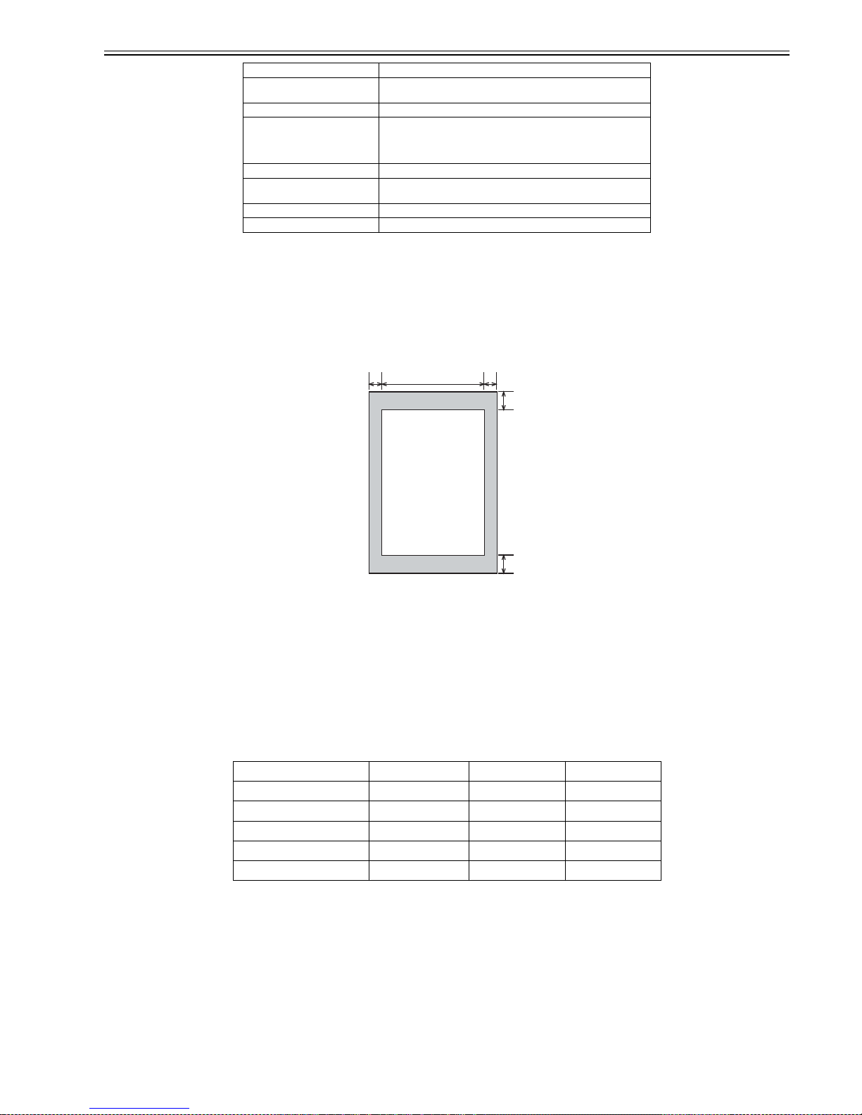
1.1.4.2 Scanning Range (copyboard)
0020-2560
i-SENSYS MF4300dn / i-SENSYS MF4350d / i-SENSYS MF4380dn / i-SENSYS MF4310/4318 / i-SENSYS MF4320d / i-SENSYS MF4330d / i-SENSYS
MF4340d / i-SENSYS D450d / i-SENSYS MF4370dn
Answering machine connection Yes.
Remote reception ID entry method
ID: 2 digits (default is 25)
Memory reception Approximately 256 sheets
Auto dialing One-touch dial: 8 (EC; 7)
Speed dial: 100
Group dial: Maximum 108 (EC; 107)
Delayed transmission No.
Broadcast transmission Number of Destination: Maximum 124 (one-touch / speed dial: 108, ten
key: 16)
Dual access Reservation Capacity: Maximum 256 jobs
Image data backup No.
[1] leading edge of original [6] trailing edge margin
[2] left margin [7] non-scanning area
[3] effective scanning width [8] scanning range
[4] right marginmargin [9] trailing edge of original
[5] leading edge margin
item A4 Letter Legal
effective scanning width 206 +2.0/-2.0 mm 212 +2.0/-2.0 mm 212 +2.0/-2.0 mm
left margin 2.0 +2.0/-2.0 mm 2.0 +2.0/-2.0 mm 2.0 +2.0/-2.0 mm
right margin 2.0 +2.0/-2.0 mm 2.0 +2.0/-2.0 mm 2.0 +2.0/-2.0 mm
leading edge margin 2.0 +2.0/-2.0 mm 2.0 +2.0/-2.0 mm 2.0 +2.0/-2.0 mm
trailing edge margin 2.0 +2.0/-2.0 mm 2.0 +2.0/-2.0 mm 2.0 +2.0/-2.0 mm
[8]
[7]
[4][2]
[5]
[6]
[3]
[1]
[9]
Chapter 1
1-12
F-1-13
T-1-8
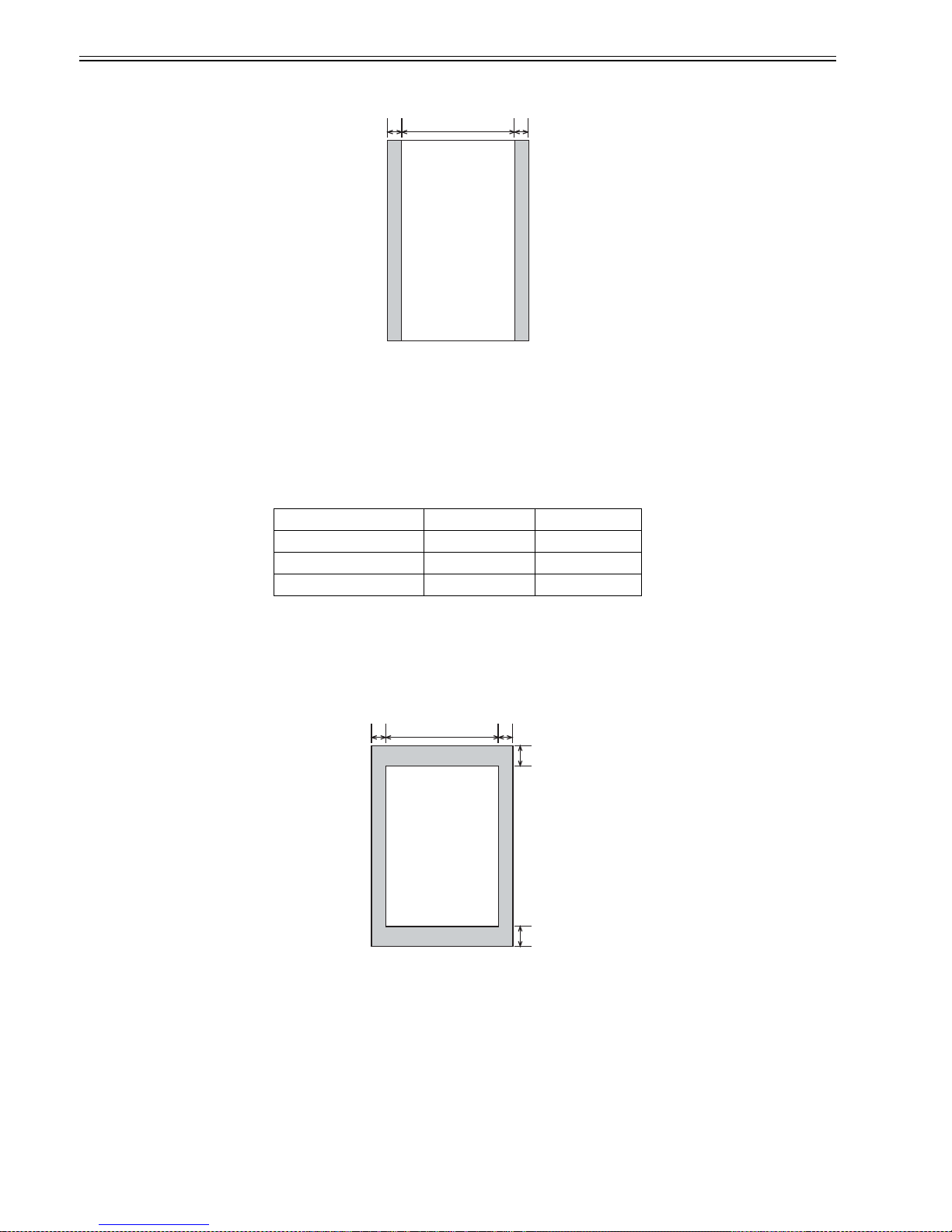
1.1.4.3 Recording Range (Copy)
0020-2561
i-SENSYS MF4300dn / i-SENSYS MF4350d / i-SENSYS MF4380dn / i-SENSYS MF4310/4318 / i-SENSYS MF4320d / i-SENSYS MF4330d / i-SENSYS
MF4340d / i-SENSYS D450d / i-SENSYS MF4370dn
F-1-14
[1] leading edge of document [4] right margin
[2] left margin [5] scanning range
[3] effective scanning width [6] trailing edge of document
item A4 Letter
effective scanning width 206 mm 212 mm
left margin 2.0 +2.0/-2.0 mm 2.0 +2.0/-2.0 mm
right margin 2.0 +2.0/-2.0 mm 2.0 +2.0/-2.0 mm
[1] leading edge of document [6] trailing edge margin
[2] left margin [7] non-scanning area
[3] effective scanning width [8] scanning range
[4] right margin [9] trailing edge of document
[5] trailing edge margin
[5]
[4][2]
[3]
[1]
[6]
[8]
[7]
[4][2]
[5]
[6]
[3]
[1]
[9]
Chapter 1
1-13
T-1-9
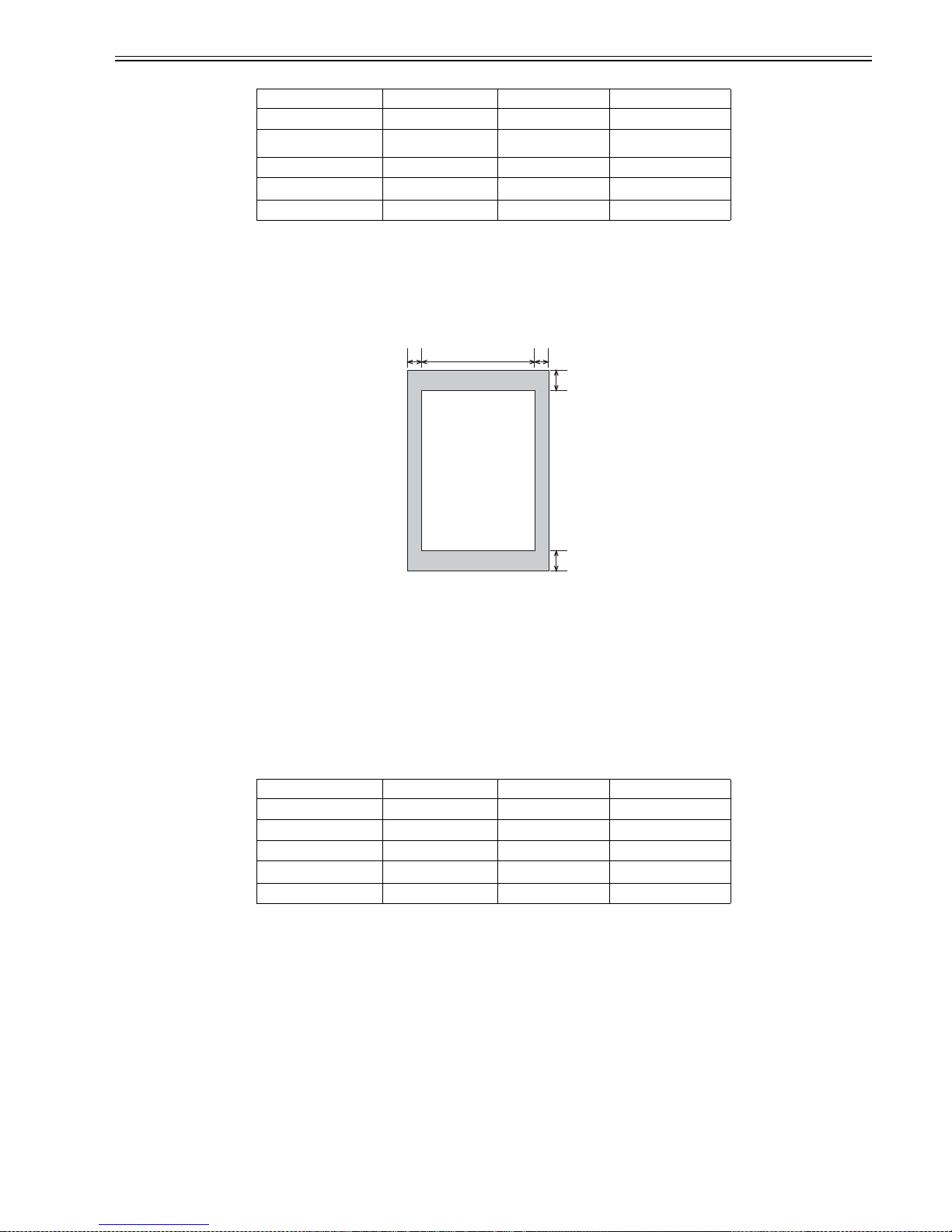
1.1.4.4 Recording Range (Reception)
0020-2562
i-SENSYS MF4300dn / i-SENSYS MF4350d / i-SENSYS MF4380dn / i-SENSYS MF4310/4318 / i-SENSYS MF4320d / i-SENSYS MF4330d / i-SENSYS
MF4340d / i-SENSYS D450d / i-SENSYS MF4370dn
F-1-15
T-1-10
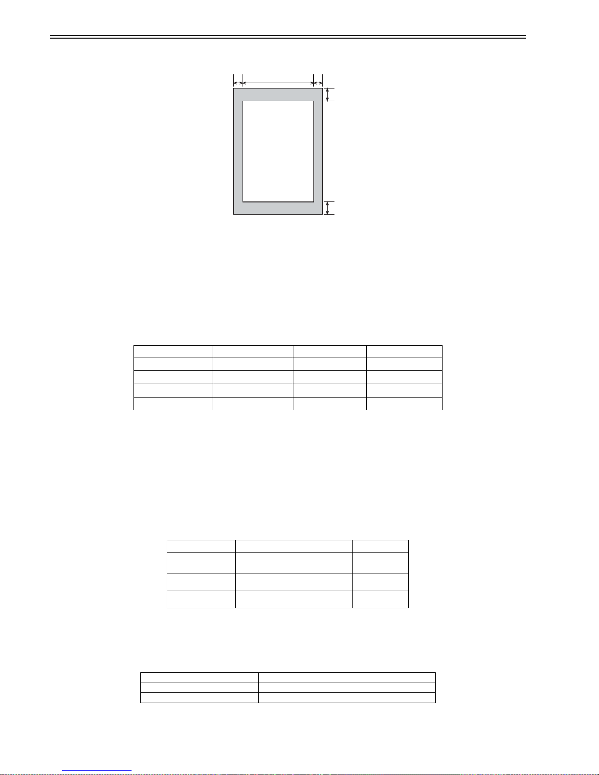
1.1.4.5 Recording Range (Printer)
0020-2563
i-SENSYS MF4300dn / i-SENSYS MF4350d / i-SENSYS MF4380dn / i-SENSYS MF4310/4318 / i-SENSYS MF4320d / i-SENSYS MF4330d / i-SENSYS
MF4340d / i-SENSYS D450d / i-SENSYS MF4370dn
item A4 Letter Legal
effective recording width 204 +1.0/-2.0 mm 210 +2.0/-2.0 mm 210 +2.0/-2.0 mm
effective recording left
margin
3.0 +2.0/-2.0 mm 3.0 +2.0/-2.0 mm 3.0 +2.0/-2.0 mm
right margin 3.0 +2.0/-2.0 mm 3.0 +2.0/-2.0 mm 3.0 +2.0/-2.0 mm
leading edge margin 4.0 +2.0/-2.0 mm 4.0 +2.0/-2.0 mm 4.0 +2.0/-2.0 mm
trailing edge margin 5.0 +2.0/-2.0 mm 5.0 +2.0/-2.0 mm 5.0 +2.0/-2.0 mm
[1] leading edge of document [6] trailing edge margin
[2]left margin [7] non-scanning area
[3] effective scanning width [8] scanning range
[4] right margin [9]trailing edge of document
[5] leading edge margin
item A4 Letter Legal
effective recording width 206 +1.0/-2.0 mm 212 +2.0/-2.0 mm 212 +2.0/-2.0 mm
left margin 2.0 +2.0/-2.0 mm 2.0 +2.0/-2.0 mm 2.0 +2.0/-2.0 mm
right margin 2.0 +2.0/-2.0 mm 2.0 +2.0/-2.0 mm 2.0 +2.0/-2.0 mm
leading edge margin 2.0 +2.0/-2.0 mm 2.0 +2.0/-2.0 mm 2.0 +2.0/-2.0 mm
trailing edge margin 6.0 +2.0/-2.0 mm 6.0 +2.0/-2.0 mm 6.0 +2.0/-2.0 mm
[8]
[7]
[4][2]
[5]
[6]
[3]
[1]
[9]
Chapter 1
1-14
F-1-16
T-1-11
1.1.4.6 Operation Environment of the Printer Driver
0020-2564
i-SENSYS MF4350d / i-SENSYS MF4380dn / i-SENSYS MF4310/4318 / i-SENSYS MF4320d / i-SENSYS MF4 330d / i-SENSYS MF434 0d / i-SENSYS D450d
/ i-SENSYS MF4370dn
Operation environment
Windows 2000, Windows XP, Windows Vista
Computer
Computer in which Windows 2000, Windows XP, or Windows Vista runs proper ly.
Hardware environment
- IBM PC or IBM compatible PC
- CD-ROM drive or network environment accessible to CD-ROM
- PC equipped with USB port
T-1-12
* Log in as a user account to which the administrator's right is authorized.
1.1.4.7 Network Specifications
0020-2565
i-SENSYS MF4380dn / i-SENSYS MF4370dn
[1] leading edge of document [6] trailing edge margin
[2] left margin [7] non-scanning area
[3] effective scanning width [8] scanning range
[4] right margin [9] trailing edge of document
[5] leading edge margin
item A4 Letter Legal
left margin 5.0 +2.0/-2.0 mm 5.0 +2.0/-2.0 mm 5.0 +2.0/-2.0 mm
right margin 5.0 +2.0/-2.0 mm 5.0 +2.0/-2.0 mm 5.0 +2.0/-2.0 mm
leading edge margin 6.0 +2.0/-2.0 mm 6.0 +2.0/-2.0 mm 6.0 +2.0/-2.0 mm
trailing edge margin 6.0 +2.0/-2.0 mm 6.0 +2.0/-2.0 mm 6.0 +2.0/-2.0 mm
OS CPU RAM
Windows 2000 Intel Pentium 133 MHz or more 128 MB or more
Windows XP Intel Pentium ii/ Celeron 300 MHz or more 128 MB or more
Windows Vista Intel Pentium 800MHz or faster 512MB or more
Connector RJ45
Communication speed 10Base-T/100Base-TX
Communication mode FULL DUPLEX/half DUPLEX
[8]
[7]
[4][2]
[5]
[6]
[3]
[1]
[9]
 Loading...