


Feb 27 2007
Service Manual
i-SENSYS LBP5300 Series


Application
This manual has been issued by Canon Inc. for qualified persons to learn technical theory, installation, maintenance, and repair
of products. This manual covers all localities where the products are sold. For this reason, there may be information in this
manual that does not apply to your locality.
Corrections
This manual may contain technical inaccuracies or typographical errors due to improvements or changes in products. When
changes occur in applicable products or in the contents of this manual, Canon will release technical information as the need
arises. In the event of major changes in the contents of this manual over a long or short period, Canon will issue a new edition
of this manual.
The following paragraph does not apply to any countries where such provisions are inconsistent with local law.
Trademarks
The product names and company names used in this manual are the registered trademarks of the individual companies.
Copyright
This manual is copyrighted with all rights reserved. Under the copyright laws, this manual may not be copied, reproduced or
translated into another language, in whole or in part, without the written consent of Canon Inc.
COPYRIGHT © 2001 CANON INC.
Printed in Japan
Caution
Use of this manual should be strictly supervised to avoid disclosure of confidential information.

Introduction
Symbols Used
This documentation uses the following symbols to indicate special information:
Symbol Description
Indicates an item of a non-specific nature, possibly classified as Note, Caution, or Warning.
Indicates an item requiring care to avoid electric shocks.
Indicates an item requiring care to avoid combustion (fire).
Indicates an item prohibiting disassembly to avoid electric shocks or problems.
Indicates an item requiring disconnection of the power plug from the electric outlet.
Indicates an item intended to provide notes assisting the understanding of the topic in question.
Indicates an item of reference assisting the understanding of the topic in question.
Provides a description of a service mode.
Provides a description of the nature of an error indication.
Memo
REF.

Introduction
The following rules apply throughout this Service Manual:
1. Each chapter contains sections explaining the purpose of specific functions and the relationship between electrical and mechanical systems with reference to the timing of operation.
In the diagrams, represents the path of mechanical drive; where a signal name accompanies the symbol , the arrow indicates the
direction of the electric signal.
The expression "turn on the power" means flipping on the power switch, closing the front door, and closing the delivery unit door, which results in
supplying the machine with power.
2. In the digital circuits, '1'is used to indicate that the voltage level of a given signal is "High", while '0' is used to indicate "Low".(The voltage value, however, differs from circuit to circuit.) In addition, the asterisk (*) as in "DRMD*" indicates that the DRMD signal goes on when '0'.
In practically all cases, the internal mechanisms of a microprocessor cannot be checked in the field. Therefore, the operations of the microprocessors
used in the machines are not discussed: they are explained in terms of from sensors to the input of the DC controller PCB and from the output of the
DC controller PCB to the loads.
The descriptions in this Service Manual are subject to change without notice for product improvement or other purposes, and major changes will be communicated in the form of Service Information bulletins.
All service persons are expected to have a good understanding of the contents of this Service Manual and all relevant Service Information bulletins and be
able to identify and isolate faults in the machine."


Contents
Contents
Chapter 1 PRODUCT DESCRIPTION
1.1 Features .....................................................................................................................................................1- 1
1.1.1 Feature ....................................................................................................................................................................1- 1
1.2 System construction ................................................................................................................................... 1- 1
1.2.1 System Construction ...............................................................................................................................................1- 1
1.2.2 System Cnstruction .................................................................................................................................................1- 1
1.3 Product Specifications ................................................................................................................................1- 2
1.3.1 Product Specifications .............................................................................................................................................1- 2
1.3.2 Product Specifications .............................................................................................................................................1- 3
1.4 Name of Parts.............................................................................................................................................1- 4
1.4.1 External View...........................................................................................................................................................1- 4
1.4.2 External View...........................................................................................................................................................1- 4
1.4.3 Cross Section View .................................................................................................................................................1- 5
1.5 Using the Machine...................................................................................................................................... 1- 6
1.5.1 Control Panel...........................................................................................................................................................1- 6
1.5.2 Control Panel...........................................................................................................................................................1- 7
1.5.3 Job Menu.................................................................................................................................................................1- 8
1.5.4 Setup Menu (1)........................................................................................................................................................1- 8
1.5.5 Setup Menu (2)......................................................................................................................................................1- 10
1.5.6 Setup Menu (3)......................................................................................................................................................1- 11
1.5.7 Setup Menu (4)......................................................................................................................................................1- 13
1.5.8 Setup Menu (5)......................................................................................................................................................1- 14
1.5.9 Utility Menu............................................................................................................................................................1- 15
1.5.10 Reset Menu .........................................................................................................................................................1- 15
1.5.11 Pickup Selection Menu ........................................................................................................................................1- 15
1.6 Safety ....................................................................................................................................................... 1- 16
1.6.1 Safety of the Laser Light........................................................................................................................................ 1- 16
1.6.2 Regulations Under the Center for Devices and Radiological Health (CDRH) .......................................................1- 16
1.6.3 Safety of Toner......................................................................................................................................................1- 16
1.6.4 Handling the Laser Unit .........................................................................................................................................1- 16
Chapter 2 TECHNICAL REFERENCE
2.1 Functional Configuration............................................................................................................................. 2- 1
2.1.1 Outline .....................................................................................................................................................................2- 1
2.2 Basic Sequense..........................................................................................................................................2- 1
2.2.1 Basic Sequence of Operation..................................................................................................................................2- 1
2.2.2 Power-On Sequence ...............................................................................................................................................2- 1
2.3 LASER EXPOSURE SYSTEM ................................................................................................................... 2- 2
2.3.1 Overview/Configuration ...........................................................................................................................................2- 2
2.3.1.1 Outline...................................................................................................................................................................................... 2- 2
2.3.2 Laser Control ........................................................................................................................................................... 2- 3
2.3.2.1 Outline...................................................................................................................................................................................... 2- 3
2.3.2.2 Image masking control ............................................................................................................................................................. 2- 4
2.3.2.3 Failure detection ...................................................................................................................................................................... 2- 5
2.3.3 Laser Scanner Motor Control ..................................................................................................................................2- 5
2.3.3.1 Outline...................................................................................................................................................................................... 2- 5
2.3.3.2 Failure detection ...................................................................................................................................................................... 2- 6
2.4 IMAGE FORMATION SYSTEM.................................................................................................................. 2- 6
2.4.1 Overview/Configuration ...........................................................................................................................................2- 6
2.4.1.1 Outline...................................................................................................................................................................................... 2- 6

Contents
2.4.1.2 Print Process............................................................................................................................................................................ 2- 7
2.4.1.3 Electrostatic latent image formation block ............................................................................................................................... 2- 8
2.4.1.4 Development block .................................................................................................................................................................. 2- 9
2.4.1.5 Transfer block ........................................................................................................................................................................ 2- 10
2.4.1.6 Fixing block ............................................................................................................................................................................ 2- 11
2.4.1.7 Cleaning block ....................................................................................................................................................................... 2- 12
2.4.2 Image Stabilizaton Control.....................................................................................................................................2- 12
2.4.2.1 Image Stabilization Control .................................................................................................................................................... 2- 12
2.4.2.2 Environment related corrective control .................................................................................................................................. 2- 12
2.4.2.3 Color gradation corrective control .......................................................................................................................................... 2- 13
2.4.2.4 Color Misregistration Corrective Control ................................................................................................................................ 2- 14
2.4.3 Toner Cartridge......................................................................................................................................................2- 16
2.4.3.1 Outline.................................................................................................................................................................................... 2- 16
2.4.3.2 Memory tag ............................................................................................................................................................................ 2- 17
2.4.3.3 Cartridge presence detection ................................................................................................................................................. 2- 17
2.4.3.4 Developing roller engagement/disengagement control.......................................................................................................... 2- 17
2.4.4 Transfer Unit ..........................................................................................................................................................2- 18
2.4.4.1 ETB Unit................................................................................................................................................................................. 2- 18
2.4.4.2 Automatic bias control............................................................................................................................................................ 2- 19
2.4.4.3 ETB cleaning.......................................................................................................................................................................... 2- 20
2.4.4.4 Transfer roller engagement/disengagement control .............................................................................................................. 2- 21
2.5 Pickup/Feeding/Delivery System.............................................................................................................. 2- 24
2.5.1 Overview/Configuration..........................................................................................................................................2- 24
2.5.1.1 Outline.................................................................................................................................................................................... 2- 24
2.5.2 Other Control .........................................................................................................................................................2- 25
2.5.2.1 Cassette pick-up mechanism ................................................................................................................................................. 2- 25
2.5.2.2 Multi-purpose tray (MPT) pick-up........................................................................................................................................... 2- 26
2.5.2.3 Skew correction by the registration shutter ............................................................................................................................ 2- 27
2.5.2.4 Transport Speed Control........................................................................................................................................................ 2- 27
2.5.2.5 Warp control........................................................................................................................................................................... 2- 28
2.5.2.6 Fixing roller pressurizing/release control ............................................................................................................................... 2- 28
2.5.3 Detecting Jams ......................................................................................................................................................2- 29
2.5.3.1 Jam Detection Outline............................................................................................................................................................ 2- 29
2.5.3.2 Delay Jams ............................................................................................................................................................................ 2- 29
2.5.3.3 Stationary Jams ..................................................................................................................................................................... 2- 30
2.5.3.4 Other Jams ............................................................................................................................................................................ 2- 30
2.5.4 Duplex Feeding......................................................................................................................................................2- 30
2.5.4.1 Outline.................................................................................................................................................................................... 2- 30
2.5.4.2 Duplexing reverse/feed operation .......................................................................................................................................... 2- 31
2.5.4.3 Duplexing pick-up operation .................................................................................................................................................. 2- 33
2.6 FIXING UNIT SYSTEM ............................................................................................................................ 2- 34
2.6.1 Overview/Configuration..........................................................................................................................................2- 34
2.6.1.1 Outline.................................................................................................................................................................................... 2- 34
2.6.2 Various Control Mechanisms.................................................................................................................................2- 35
2.6.2.1 Fixing Temperature Control ................................................................................................................................................... 2- 35
2.6.3 Protective Functions ..............................................................................................................................................2- 36
2.6.3.1 outline .................................................................................................................................................................................... 2- 36
2.6.3.2 Failure detection .................................................................................................................................................................... 2- 36
2.7 EXTERNAL AND CONTROLS SYSTEM ................................................................................................. 2- 36
2.7.1 Power Supply.........................................................................................................................................................2- 36
2.7.1.1 Power Supply ......................................................................................................................................................................... 2- 36
2.7.1.2 Other Function ....................................................................................................................................................................... 2- 37
2.8 ENGINE CONTROL SYSTEM ................................................................................................................. 2- 38
2.8.1 Construction...........................................................................................................................................................2- 38
2.8.1.1 Outline.................................................................................................................................................................................... 2- 38
2.8.2 DC Controller .........................................................................................................................................................2- 38
2.8.2.1 Outline.................................................................................................................................................................................... 2- 38
2.8.2.2 Operation of each block ......................................................................................................................................................... 2- 39
2.8.2.3 Fan/Motor Control .................................................................................................................................................................. 2- 40
2.8.2.4 Drum motor failure detection.................................................................................................................................................. 2- 40

Contents
2.8.2.5 ETB motor failure detection ................................................................................................................................................... 2- 40
2.8.2.6 Fixing motor failure detection ................................................................................................................................................. 2- 40
2.8.2.7 Exhaust fan failure detection.................................................................................................................................................. 2- 40
2.8.2.8 Duplexing cooling fan failure detection .................................................................................................................................. 2- 41
2.8.3 Video Controller PCB ............................................................................................................................................2- 41
2.8.3.1 Outline.................................................................................................................................................................................... 2- 41
2.8.3.2 Overview ................................................................................................................................................................................ 2- 41
2.8.3.3 Outline of the Block ................................................................................................................................................................ 2- 42
2.8.3.4 Outline of the Block ................................................................................................................................................................ 2- 43
Chapter 3 DISASSEMBLY AND ASSEMBLY
3.1 EXTERNAL AND CONTROLS SYSTEM ...................................................................................................3- 1
3.1.1 Rear Cover ..............................................................................................................................................................3- 1
3.1.1.1 Removing the Rear Cover ....................................................................................................................................................... 3- 1
3.1.2 Right Cover..............................................................................................................................................................3- 1
3.1.2.1 Preparation for Removing the Right Cover .............................................................................................................................. 3- 1
3.1.2.2 Removing the Right Cover ....................................................................................................................................................... 3- 1
3.1.3 Left Cover ................................................................................................................................................................3- 1
3.1.3.1 Preparation for Removing the Left Cover ................................................................................................................................ 3- 1
3.1.3.2 Removing the Left Cover ......................................................................................................................................................... 3- 1
3.1.4 Upper Cover ............................................................................................................................................................3- 2
3.1.4.1 Preparation for Removing the Upper Cover............................................................................................................................. 3- 2
3.1.4.2 Removing the Upper Cover ..................................................................................................................................................... 3- 2
3.1.5 Front Cover..............................................................................................................................................................3- 2
3.1.5.1 Preparation for Removing the Front Cover .............................................................................................................................. 3- 2
3.1.5.2 Removing the Front Cover ....................................................................................................................................................... 3- 2
3.1.6 Main Drive Unit ........................................................................................................................................................3- 3
3.1.6.1 Preparation for Removing the Main Drive Unit ........................................................................................................................ 3- 3
3.1.6.2 Removing the Main Drive Unit ................................................................................................................................................. 3- 3
3.1.6.3 Points to Note When Mounting Main Drive Unit....................................................................................................................... 3- 5
3.1.7 Operation Panel Unit ...............................................................................................................................................3- 7
3.1.7.1 Preparation for Removing the Control Panel ........................................................................................................................... 3- 7
3.1.7.2 Removing the Control Panel .................................................................................................................................................... 3- 7
3.1.8 DC Controller PCB ..................................................................................................................................................3- 7
3.1.8.1 Before Removing the DC Controller PCB ................................................................................................................................ 3- 7
3.1.8.2 Preparation for Removing the DC Controller PCB ................................................................................................................... 3- 7
3.1.8.3 Removing the DC Controller PCB............................................................................................................................................ 3- 7
3.1.9 Video Controller PCB ..............................................................................................................................................3- 8
3.1.9.1 Preparation for Removing the Video Controller PCB ............................................................................................................... 3- 8
3.1.9.2 Preparation for Removing the Video Controller PCB ............................................................................................................... 3- 8
3.1.9.3 Removing the Video Controller PCB........................................................................................................................................ 3- 8
3.1.9.4 Removing the Video Controller PCB........................................................................................................................................ 3- 8
3.1.10 Memory Controller PCB.........................................................................................................................................3- 9
3.1.10.1 Before Removing the Memory Controller PCB ...................................................................................................................... 3- 9
3.1.10.2 Preparation for Removing the Memory Controller PCB ......................................................................................................... 3- 9
3.1.10.3 Removing the Memory Controller PCB .................................................................................................................................. 3- 9
3.1.11 Interface Controller PCB...................................................................................................................................... 3- 10
3.1.11.1 Removing the Network Interface Board ............................................................................................................................... 3- 10
3.1.12 Duplexing Driver PCB.......................................................................................................................................... 3- 10
3.1.12.1 Preparation for Removing the Duplexing Driver PCB .......................................................................................................... 3- 10
3.1.12.2 Removing the Duplexing Driver PCB ................................................................................................................................... 3- 10
3.1.13 Low-Voltage Power Supply Assembly .................................................................................................................3- 10
3.1.13.1 Preparation for Removing the Low-Voltage Power Supply PCB.......................................................................................... 3- 10
3.1.13.2 Removing the Low-Voltage Power Supply PCB .................................................................................................................. 3- 10
3.1.14 High-voltage PCB ................................................................................................................................................3- 11
3.1.14.1 Preparation for Removing the High-Voltage Power Supply PCB ......................................................................................... 3- 11
3.1.14.2 Removing the High-Voltage Power Supply PCB.................................................................................................................. 3- 11
3.1.15 Cooling Fan .........................................................................................................................................................3- 11
3.1.15.1 Preparation for Removing the Cooling Fan .......................................................................................................................... 3- 11

Contents
3.1.15.2 Removing the Cooling Fan................................................................................................................................................... 3- 12
3.1.16 Duplex Fan...........................................................................................................................................................3- 12
3.1.16.1 Preparation for Removing the Duplexing Fan ...................................................................................................................... 3- 12
3.1.16.2 Removing the Duplexing Fan............................................................................................................................................... 3- 12
3.2 LASER EXPOSURE SYSTEM ................................................................................................................. 3- 13
3.2.1 Laser Scanner Unit ................................................................................................................................................3- 13
3.2.1.1 Preparation for Removing the Laser / Scanner Unit .............................................................................................................. 3- 13
3.2.1.2 Preparation for Removing the Laser / Scanner Unit .............................................................................................................. 3- 13
3.2.1.3 Removing the Laser / Scanner Unit ....................................................................................................................................... 3- 13
3.3 IMAGE FORMATION SYSTEM................................................................................................................ 3- 14
3.3.1 Developing Estrangement Solenoid.......................................................................................................................3- 14
3.3.1.1 Preparation for Removing the Developing Estrangement Solenoid....................................................................................... 3- 14
3.3.1.2 Removing the Developing Estrangement Solenoid ............................................................................................................... 3- 14
3.3.1.3 Points to Note when Attaching the Developing Estrangement Solenoid ............................................................................... 3- 14
3.3.2 ETB Unit.................................................................................................................................................................3- 15
3.3.2.1 Removing the ETB Unit ......................................................................................................................................................... 3- 15
3.3.3 ETB Motor..............................................................................................................................................................3- 15
3.3.3.1 Preparation for Removing the ETB Motor .............................................................................................................................. 3- 15
3.3.3.2 Removing the ETB Motor....................................................................................................................................................... 3- 15
3.3.4 ETB Estrangement Solenoid..................................................................................................................................3- 16
3.3.4.1 Preparation for Removing the ETB Estrangement Solenoid.................................................................................................. 3- 16
3.3.4.2 Removing the ETB Estrangement Solenoid .......................................................................................................................... 3- 16
3.3.5 Toner Cartridge Motor............................................................................................................................................3- 17
3.3.5.1 Preparation for Removing the Toner Cartridge Motor............................................................................................................ 3- 17
3.3.5.2 Removing the Toner Cartridge Motor .................................................................................................................................... 3- 17
3.3.6 Color Misregistration/Image Density Sensor..........................................................................................................3- 17
3.3.6.1 Preparation for Removing the Color Displacement / Density Sensor .................................................................................... 3- 17
3.3.6.2 Removing the Color Displacement / Density Sensor ............................................................................................................. 3- 17
3.4 PICKUP/FEEDING/DELIVERY SYSTEM................................................................................................. 3- 17
3.4.1 Paper Pick-up Feeder Unit.....................................................................................................................................3- 17
3.4.1.1 Preparation for Removing the Pick-Up / Feed Assembly....................................................................................................... 3- 17
3.4.1.2 Removing the Pick-Up / Feed Assembly ............................................................................................................................... 3- 17
3.4.2 Pickup Motor..........................................................................................................................................................3- 18
3.4.2.1 Preparation for Removing the Pick-Up Motor ........................................................................................................................ 3- 18
3.4.2.2 Removing the Pick-Up Motor ................................................................................................................................................. 3- 18
3.4.3 Cassette Pickup Roller...........................................................................................................................................3- 19
3.4.3.1 Removing the Cassette Pick-Up Roller.................................................................................................................................. 3- 19
3.4.4 Cassette Pick-up Solenoid.....................................................................................................................................3- 19
3.4.4.1 Preparation for Removing the Cassette Pick-Up Solenoid .................................................................................................... 3- 19
3.4.4.2 Removing the Cassette Pick-Up Solenoid ............................................................................................................................. 3- 19
3.4.5 Cassette Separation Pad.......................................................................................................................................3- 21
3.4.5.1 Removing the Cassette Separation Pad ................................................................................................................................ 3- 21
3.4.6 Manual Pickup Roller.............................................................................................................................................3- 21
3.4.6.1 Removing the Manual Feed Pick-Up Roller ........................................................................................................................... 3- 21
3.4.7 Multi-purpose Pickup Solenoid ..............................................................................................................................3- 21
3.4.7.1 Preparation for Removing the Manual Feed Pick-Up Solenoid ............................................................................................. 3- 21
3.4.7.2 Removing the Manual Feed Pick-Up Solenoid ...................................................................................................................... 3- 21
3.4.8 Manual Separation Pad .........................................................................................................................................3- 23
3.4.8.1 Preparation for Removing the Manual Feed Separation Pad ................................................................................................ 3- 23
3.4.8.2 Removing the Manual Feed Separation Pad ......................................................................................................................... 3- 23
3.4.9 Duplexing Reverse Motor ......................................................................................................................................3- 23
3.4.9.1 Preparation for Removing the Duplexing Reversing Motor.................................................................................................... 3- 23
3.4.9.2 Removing the Duplexing Reversing Motor ............................................................................................................................ 3- 23
3.4.10 Duplexing Feed Motor..........................................................................................................................................3- 24
3.4.10.1 Preparation for Removing the Duplexing Feed Motor.......................................................................................................... 3- 24
3.4.10.2 Removing the Duplexing Feed Motor................................................................................................................................... 3- 24
3.4.11 Duplexing Flapper Solenoid .................................................................................................................................3- 25
3.4.11.1 Preparation for Removing the Duplexing Flapper Solenoid ................................................................................................. 3- 25
3.4.11.2 Removing the Duplexing Flapper Solenoid.......................................................................................................................... 3- 25

Contents
3.5 FIXING SYSTEM ...................................................................................................................................... 3- 25
3.5.1 Fixing Assembly ....................................................................................................................................................3- 25
3.5.1.1 Removing the Fixing Assembly.............................................................................................................................................. 3- 25
3.5.2 Fixing Sleeve Unit.................................................................................................................................................. 3- 26
3.5.2.1 Preparation for Removing the Fixing Sleeve Unit .................................................................................................................. 3- 26
3.5.2.2 Removing the Fixing Sleeve Unit ........................................................................................................................................... 3- 26
3.5.3 Fixing Motor...........................................................................................................................................................3- 28
3.5.3.1 Preparation for Removing the Fixing Motor ........................................................................................................................... 3- 28
3.5.3.2 Removing the Fixing Motor .................................................................................................................................................... 3- 28
Chapter 4 MAINTENANCE AND INSPECTION
4.1 Periodically Replaced Parts........................................................................................................................ 4- 1
4.1.1 Periodically Replaced Parts.....................................................................................................................................4- 1
4.2 Consumables..............................................................................................................................................4- 1
4.2.1 Durables Replaced by the User...............................................................................................................................4- 1
4.2.2 Durables Replaced by the Service Person..............................................................................................................4- 1
4.3 Periodical Service ....................................................................................................................................... 4- 1
4.3.1 Periodic Service.......................................................................................................................................................4- 1
4.4 Cleaning ..................................................................................................................................................... 4- 1
4.4.1 Pick-up roller............................................................................................................................................................4- 1
4.4.2 Separation pad ........................................................................................................................................................4- 1
4.4.3 Registration roller ....................................................................................................................................................4- 1
4.4.4 Registration shutter .................................................................................................................................................4- 1
4.4.5 Feed guide...............................................................................................................................................................4- 1
4.4.6 Delivery roller...........................................................................................................................................................4- 1
4.4.7 Fixing inlet guide......................................................................................................................................................4- 1
4.4.8 Color misregistration/Density sensor.......................................................................................................................4- 1
Chapter 5 TROUBLESHOOTING
5.1 MEASUREMENT AND ADJUSTMENT ......................................................................................................5- 1
5.1.1 Adjustment of Electrical Components.....................................................................................................................5- 1
5.1.1.1 After Replacing the DC controller PCB .................................................................................................................................... 5- 1
5.1.1.2 After Replacing the DC controller PCB .................................................................................................................................... 5- 1
5.1.1.3 After Replacing the Video Controller PCB ............................................................................................................................... 5- 1
5.1.1.4 After Replacing the Video Controller PCB ............................................................................................................................... 5- 1
5.1.1.5 Replacing EEPROM (When E747-000 occurs) ....................................................................................................................... 5- 1
5.1.2 Adjustment of Fixing System ..................................................................................................................................5- 1
5.1.2.1 Checking the Nip Width (fixing pressure roller)........................................................................................................................ 5- 1
5.2 SERVICE TOOLS.......................................................................................................................................5- 3
5.2.1 Standard Tools ........................................................................................................................................................5- 3
5.2.2 Solvent/Oil List.........................................................................................................................................................5- 3
5.3 ERROR CODE ........................................................................................................................................... 5- 3
5.3.1 Error Code ...............................................................................................................................................................5- 3
5.3.2 Error Code ...............................................................................................................................................................5- 5
5.3.3 A4-XX_ERROR .......................................................................................................................................................5- 9
5.3.4 A5-XX_ERROR .......................................................................................................................................................5- 9
5.3.5 A7-XX_ERROR .......................................................................................................................................................5- 9
5.3.6 D7-XX_ERROR .....................................................................................................................................................5- 10
5.3.7 D8-XX_ERROR .....................................................................................................................................................5- 10
5.4 Version Up................................................................................................................................................ 5- 10
5.4.1 Outline ................................................................................................................................................................... 5- 10
5.4.1.1 Overview of Upgrading Work ................................................................................................................................................. 5- 10
5.4.1.2 Construction of Firmware ....................................................................................................................................................... 5- 10
5.4.1.3 Outline of the Service Support Tool ....................................................................................................................................... 5- 11
5.4.2 Making Preparations..............................................................................................................................................5- 13

Contents
5.4.2.1 Registering the Firmware ....................................................................................................................................................... 5- 13
5.4.2.2 Making Connections .............................................................................................................................................................. 5- 15
5.4.3 Downloading the System Software........................................................................................................................5- 16
5.4.3.1 Downloading Procedure......................................................................................................................................................... 5- 16
5.5 Service Mode ........................................................................................................................................... 5- 19
5.5.1 Outline....................................................................................................................................................................5- 19
5.5.1.1 Outline.................................................................................................................................................................................... 5- 19
5.5.1.2 Outline.................................................................................................................................................................................... 5- 20
5.5.2 Service Mode Table...............................................................................................................................................5- 20
5.5.2.1 Service Mode Items ............................................................................................................................................................... 5- 20
5.5.2.2 Service Mode ......................................................................................................................................................................... 5- 20

Chapter 1 PRODUCT DESCRIPTION


Contents
Contents
1.1 Features ..........................................................................................................................................................................1-1
1.1.1 Feature.......................................................................................................................................................................................... 1-1
1.2 System construction .......................................................................................................................................................1-1
1.2.1 System Construction .................................................................................................................................................................... 1-1
1.2.2 System Cnstruction ...................................................................................................................................................................... 1-1
1.3 Product Specifications....................................................................................................................................................1-2
1.3.1 Product Specifications ................................................................................................................................................................. 1-2
1.3.2 Product Specifications ................................................................................................................................................................. 1-3
1.4 Name of Parts.................................................................................................................................................................1-4
1.4.1 External View .............................................................................................................................................................................. 1-4
1.4.2 External View .............................................................................................................................................................................. 1-4
1.4.3 Cross Section View...................................................................................................................................................................... 1-5
1.5 Using the Machine .........................................................................................................................................................1-6
1.5.1 Control Panel ............................................................................................................................................................................... 1-6
1.5.2 Control Panel ............................................................................................................................................................................... 1-7
1.5.3 Job Menu...................................................................................................................................................................................... 1-8
1.5.4 Setup Menu (1) ............................................................................................................................................................................ 1-8
1.5.5 Setup Menu (2) .......................................................................................................................................................................... 1-10
1.5.6 Setup Menu (3) .......................................................................................................................................................................... 1-11
1.5.7 Setup Menu (4) .......................................................................................................................................................................... 1-13
1.5.8 Setup Menu (5) .......................................................................................................................................................................... 1-14
1.5.9 Utility Menu............................................................................................................................................................................... 1-15
1.5.10 Reset Menu .............................................................................................................................................................................. 1-15
1.5.11 Pickup Selection Menu ............................................................................................................................................................ 1-15
1.6 Safety ...........................................................................................................................................................................1-16
1.6.1 Safety of the Laser Light............................................................................................................................................................ 1-16
1.6.2 Regulations Under the Center for Devices and Radiological Health (CDRH).......................................................................... 1-16
1.6.3 Safety of Toner .......................................................................................................................................................................... 1-16
1.6.4 Handling the Laser Unit............................................................................................................................................................. 1-16

Chapter 1
1-1
1.1 Features
1.1.1 Feature
0013-7282
/ i-SENSYS LBP5360 / i-SENSYS LBP5300
1. High-speed printing and high image quality
This printer realizes high-speed printing for both full-color and monochrome print. Regardless of this high-speed, the toner with fine particle enables to produce
vivid image with the resolution of 600 dpi.
Full color/Monochrome: 22 pages/min.
2. Electrostatic Transportation Belt (ETB)
This printer adopts the "Electrostatic Transportation Belt" (hereafter ETB) method for image transfer and paper feed process. In order to realize the high-speed
color printing, toner images of all four colors on the photosensitive drum are transferred onto paper directly.
3. Four consecutive drum method (Inline method)
This printer adopts the four consecutive drum method. The toner cartridges are aligned vertically and all four colors are transferred on paper in one sequential
operation. This realizes highspeed color printing, as this method needs less time to transfer compared to the rotary method where each color is transferred
separately.
4. Color on-demand fixing method
The machine uses an on-demand fixing method combined with a ceramic heater so far mostly used in a mono-color printer. The fact has led to a shorter warmup period and lower energy consumption.
5. 500-sheet paper feeder
This printer can be installed optional 500-sheet paper feeder in addition to the standard MPT (100 sheets available) and cassette (250 sheets available). This
enables high-volume printing of maximum 850 sheets.
6. Automatic duplex printing
There are simplex and duplex models for this printer. Automatic duplex printing is available with the duplex model.
1.2 System construction
1.2.1 System Construction
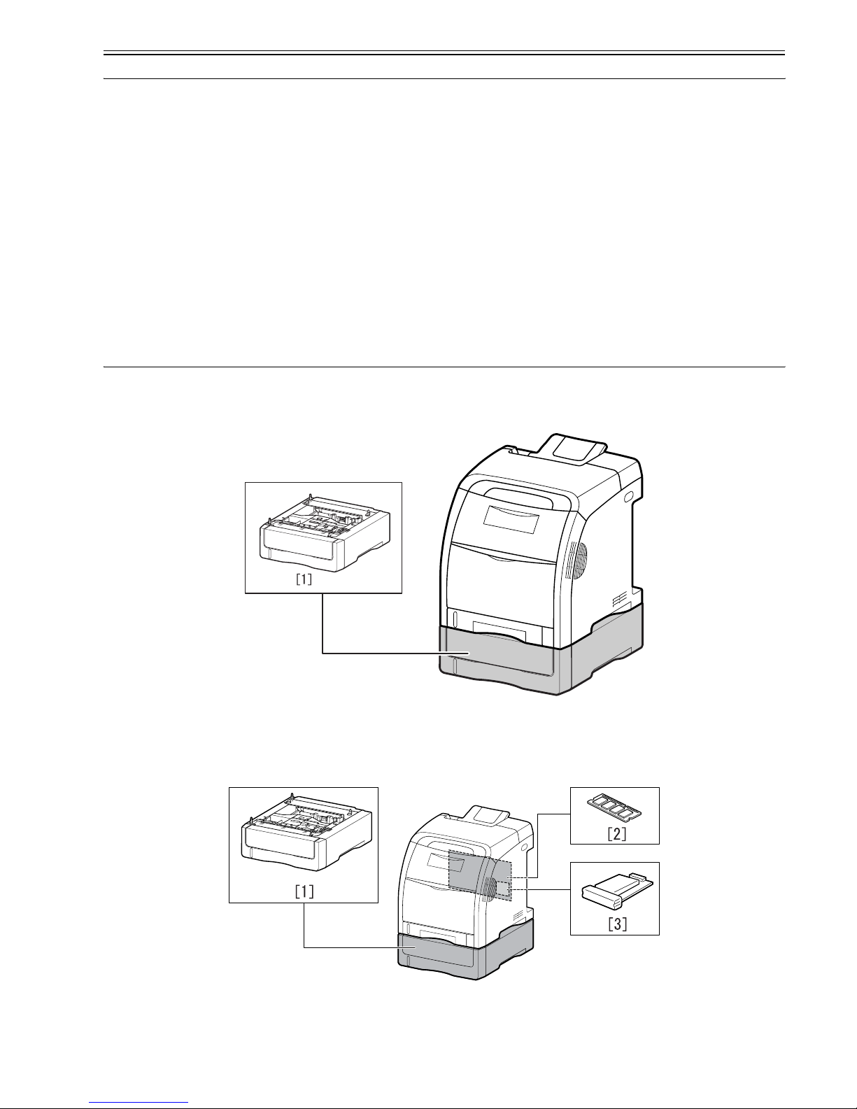
0014-2771
i-SENSYS LBP5300
F-1-1
[1] Paper Feeder PF-93
1.2.2 System Cnstruction
0014-7502
i-SENSYS LBP5360
F-1-2
[1] Paper Feeder PF-93
[2] RAM
[3] Hard Disc HD-93

Chapter 1
1-2
1.3 Product Specifications
1.3.1 Product Specifications
0015-7509
i-SENSYS LBP5300
Body installation method Desktop page printer
Photosensitive medium OPC drum
Charging method Roller charging
Exposure method Laser scanning
Development method Contact development
Transfer method By Electrostatic Transportation Belt
Separation method Curvature
Pickup method By cassette/manual feeder
Cassette pickup method By separation pad
Drum cleaning method By blade
Trasnsfer cleaning method Drum static collection
Fixing method On-demand
Delivery method Face-down
Contrast adjustment function Auto
Toner level detection function Available
Toner type non-magnetic, 1-component dry toner
Toner supply type By EP cartridge (Printable pages: approx. 6,000 pages (Canon Genuine
Cartridge, and for A4 or Letter size paper at 5 % page coverage with the
default print density setting))
Warm-up time 0 second from standby mode (20°C (68°F)
(40 seconds or less from power ON
Image margin (Leading edge) 5.0+1.5/-1.5mm
Image margin (Trailing edge) 5.0+1.5/-1.5mm
Image margin (Left/right) 5.0+1.0/-1.0mm
Number of gradations 16 gradations
Printing resolution 600dpi x 600dpi
First print time 10.1 sec or less (approx.; both mono- and full-color)
Print speed (A4) 21 impressions/min (approx.; both mono- and full color)
Cassette paper size A4, B5, A5, LGL, LTR, Exective, Foolscap, 16K
Custom sizes
When loading paper in portrait orientation:
Width 148.0 to 215.9 mm; Length 210.0 to 355.6 mm
When loading paper in landscape orientation (Only when UFR II Printer
Driver is used):
Width 210.0 to 215.9 mm; Length 210.0 to 215.9 mm
Multifeeder paper size A4, B5, A5, LGL, LTR, Exective, Stantmrnt, Foolscap, 16K, Envelope
DL, Envelope COM10, Envelope C5, Envelope Monarch, Envelope B5,
Index Card
Custom sizes
When loading paper in portrait orientation:
Width 76.2 to 215.9 mm; Length 127.0 to 355.6 mm
When loading paper in landscape orientation (Only when UFR II Printer
Driver is used):
Width 127.0 to 215.9 mm; Length 127.0 to 215.9 mm
Cassette paper type Plain paper (60 to 105 g/m2)
Multifeeder tray paper type Plain paper (60 to 105 g/m2), heavy paper (106 to 216 g/m2), Coated
paper, Envelope, Label, Transparency
Cassette capacity 250 sheets (64 g/m2)
Multifeeder tray capacity approx. 100 sheets (64 g/m2)
Delivery tray stack 200 sheets (64 g/m2)
Memory 8 MB (addition not possible)
Auto gradation correction Available
Operating environment
(Temperature range)
10 to 30 deg C
Operating environment
(Humidity range)
10 to 80%RH
Operating environment
(Atmospheric pressure)
810.6 to 1013.3 hpa (0.8 to 1.0 atm)
Noise 35 dB or less (standby); 53 dB or less (print)
Power supply rating AC220V - 240V 50/60 Hz
Power consumption (Maximum) 1213W or less
Power consumption Average during standby: approx. 45 W
Average during operation: approx. 415 W
Dimensions 412mm(W) x 453mm(D) x 437.7mm(H)

Chapter 1
1-3
1.3.2 Product Specifications
0015-7508
i-SENSYS LBP5360
Weight 22.0 kg (approx.; excluding cartridges)
Body installation method Desktop page printer
Photosensitive medium OPC drum
Charging method Roller charging
Exposure method Laser scanning
Development method Contact development
Transfer method By Electrostatic Transportation Belt
Separation method Curvature
Pickup method By cassette/manual feeder
Cassette pickup method By separation pad
Drum cleaning method By blade
Trasnsfer cleaning method Drum static collection
Fixing method On-demand
Delivery method Face-down
Contrast adjustment function Auto
Toner level detection function Available
Toner type non-magnetic, 1-component dry toner
Toner supply type By EP cartridge (Printable pages: approx. 6,000 pages (Canon Genuine
Cartridge, and for A4 or Letter size paper at 5 % page coverage with the
default print density setting))
Warm-up time 0 second from standby mode (20°C (68°F)
(40 seconds or less from power ON
Image margin (Leading edge) 5.0+1.5/-1.5mm
Image margin (Trailing edge) 5.0+1.5/-1.5mm
Image margin (Left/right) 5.0+1.0/-1.0mm
Number of gradations 16 gradations
Printing resolution 600dpi x 600dpi
First print time 10.1 sec or less (approx.; both mono- and full-color)
Print speed (A4) 21 impressions/min (approx.; both mono- and full color)
Cassette paper size A4, B5, A5, LGL, LTR, Exective, Foolscap, 16K
Custom sizes
When loading paper in portrait orientation:
Width 148.0 to 215.9 mm; Length 210.0 to 355.6 mm
When loading paper in landscape orientation (Only when UFR II Printer
Driver is used):
Width 210.0 to 215.9 mm; Length 210.0 to 215.9 mm
Multifeeder paper size A4, B5, A5, LGL, LTR, Exective, Stantmrnt, Foolscap, 16K, Envelope
DL, Envelope COM10, Envelope C5, Envelope Monarch, Envelope B5,
Index Card
Custom sizes
When loading paper in portrait orientation:
Width 76.2 to 215.9 mm; Length 127.0 to 355.6 mm
When loading paper in landscape orientation (Only when UFR II Printer
Driver is used):
Width 127.0 to 215.9 mm; Length 127.0 to 215.9 mm
Cassette paper type Plain paper (60 to 105 g/m2)
Multifeeder tray paper type Plain paper (60 to 105 g/m2), heavy paper (106 to 216 g/m2), Coated
paper, Envelope, Label, Transparency
Cassette capacity 250 sheets (64 g/m2)
Multifeeder tray capacity approx. 100 sheets (64 g/m2)
Delivery tray stack 200 sheets (64 g/m2)
Memory 128 MB (384 MB max.)
Auto gradation correction Available
Operating environment
(Temperature range)
10 to 30 deg C
Operating environment
(Humidity range)
10 to 80%RH
Operating environment
(Atmospheric pressure)
810.6 to 1013.3 hpa (0.8 to 1.0 atm)
Noise 35 dB or less (standby); 53 dB or less (print)
Power supply rating AC220V - 240V 50/60 Hz
Power consumption (Maximum) 1257W or less
Power consumption Average during standby: approx. 45W
Average during operation: approx. 416W
Dimensions 412mm(W) x 453mm(D) x 437.7mm(H)
Weight 22.0 kg (approx.; excluding cartridges)
Chapter 1
1-4
1.4 Name of Parts
1.4.1 External View
0014-2125
i-SENSYS LBP5300
F-1-3
F-1-4
1.4.2 External View
0014-9930
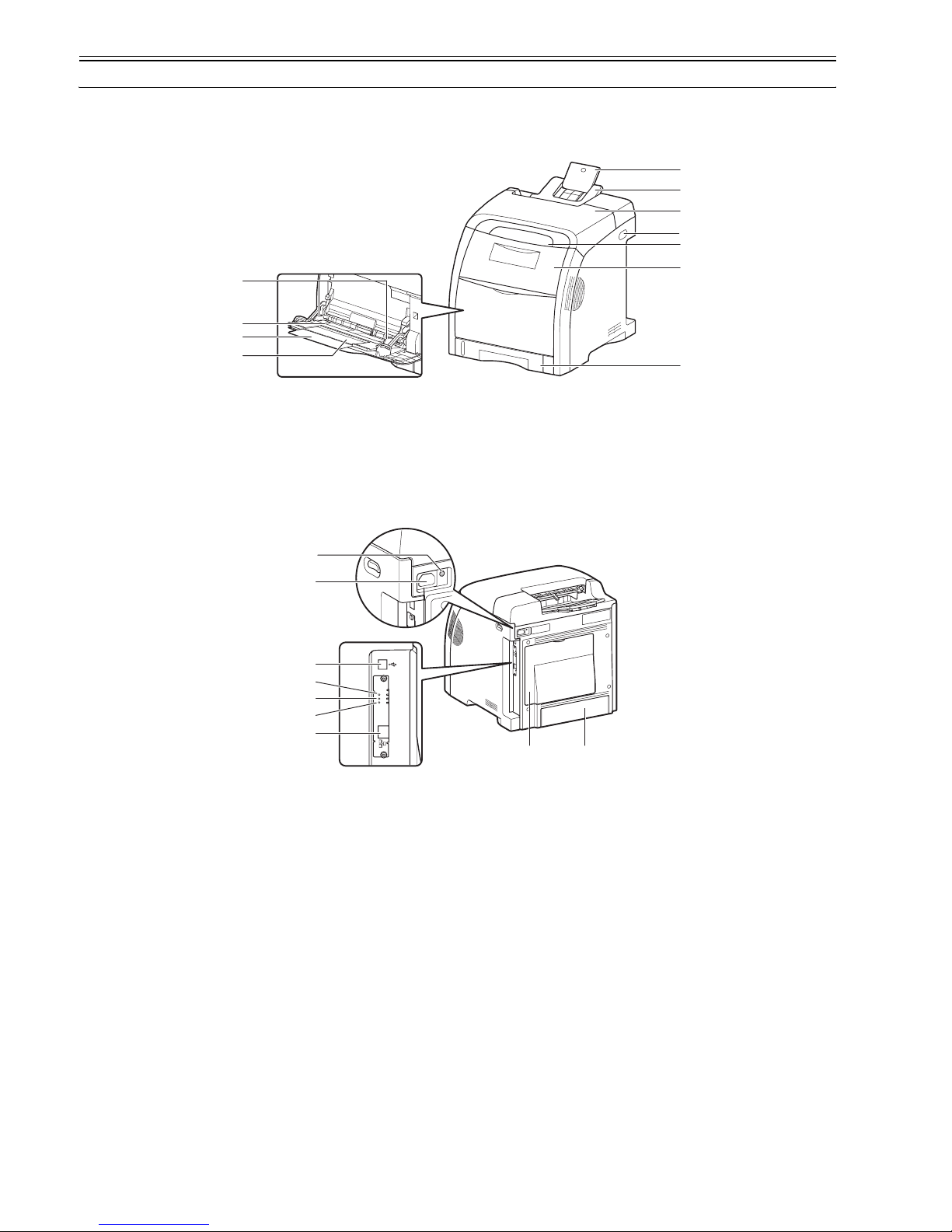
/ i-SENSYS LBP5360
[1] Auxiliary Tray [2] Output Tray
[3] Top Cover [4] Power Switch
[5] Control Panel [6] Front Cover
[7] Paper Cassette [8] Tray Extension
[9] Auxiliary Tray [10] Multi-purpose Tray
[11] Paper Guides
[1] Cassette Protective Cover [2] Rear Cover
[3] LAN Connector [4] 100 Indicator (Green)
[5] LNK Indicator (Green) [6] ERR Indicator (Orange)
[7] USB Connector [8] Power Socket
[11]
[10]
[9]
[8]
[1]
[2]
[3]
[4]
[5]
[6]
[7]
[7]
[8]
[6]
[5]
[4]
[3]
[9]
[1][2]
Chapter 1
1-5
F-1-5
F-1-6
1.4.3 Cross Section View
0014-2126
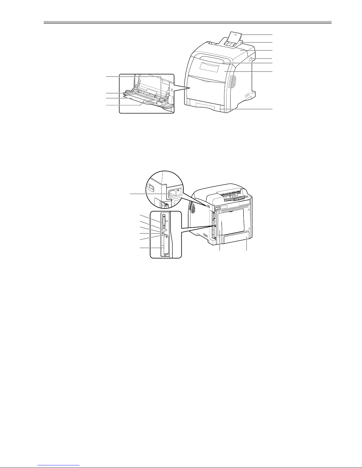
/ i-SENSYS LBP5360 / i-SENSYS LBP5300
[1] Auxiliary Tray [2] Output Tray
[3] Top Cover [4] Power Switch
[5] Control Panel [6] Front Cover
[7] Paper Cassette [8] Tray Extension
[9] Auxiliary Tray [10] Multi-purpose Tray
[11] Paper Guides
[1] Cassette Protective Cover [2] Rear Cover
[3] Expansion Slot [4] USB Connector
[5] 100 Indicator (Green) [6] LNK Indicator (Green)
[7] LAN Connector [8] Parallel Connector
[9] Power Socket
[11]
[10]
[9]
[8]
[1]
[2]
[3]
[4]
[5]
[6]
[7]
[9]
[7]
[8]
[6]
[5]
[4]
[3]
[1][2]
Chapter 1
1-6
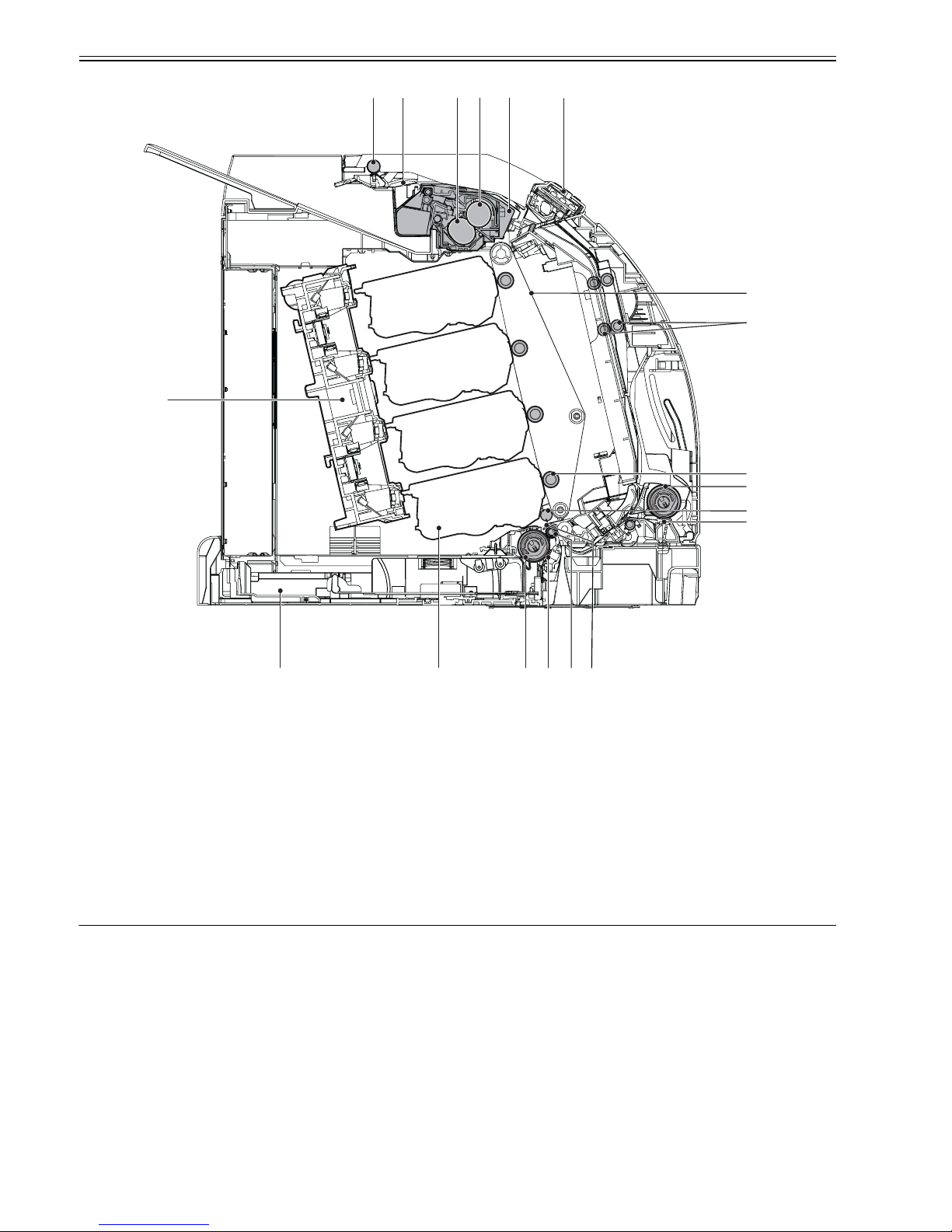
F-1-7
1.5 Using the Machine
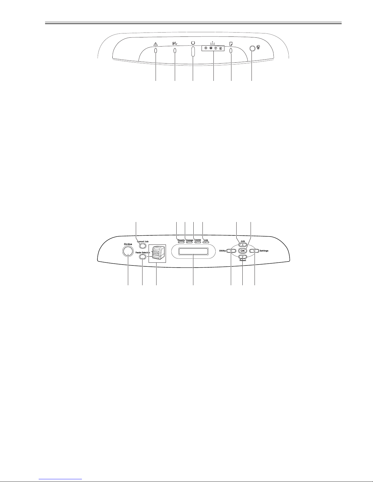
1.5.1 Control Panel
0014-2127
i-SENSYS LBP5300
[1] Duplexing reverse roller [2] Duplexing flapper
[3] Fixing sleeve [4] Fixing pressure roller
[5] Fixing unit [6] Control panel
[7] ETB [8] Duplexing feed roller
[9] Transfer roller [10] Multi-purpose tray pick-up roller
[11] Attraction roller [12] Multi-purpose tray paper separation pad
[13] Registration shutter [14] Registration roller
[15] Cassette paper separation pad [16] Cassette pick-up roller
[17] EP cartridge [18] Cassette
[19] Laser/Scanner unit
[1]
[2]
[3]
[4]
[5]
[6]
[7]
[8]
[9]
[10]
[11]
[12]
[16] [14][13][15]
[17]
[18]
[19]
Chapter 1
1-7
F-1-8
[1] Alarm Indicator (Orange)
On: Service call is occurring.
Blinking: An error is occurring, disabling printing.
[2] Paper Jam Indicator (Orange)
Blinking: A paper jam is occurring, disabling printing.
[3] Ready Indicator (Green)
On: The printer is in the sleep mode and ready to print.
Blinking: The printer is busy performing some kind of processing or operation, such as printing, warming up, calibrating, or pausing a job.
[4] Toner Indicator (Orange)
On: Toner cartridge replacement is required.
Blinking: Cannot print because toner cartridge replacement is required or any toner cartridge is not installed properly.
Indicator of the color that requires toner cartridge replacement comes on or blinks. "K", "Y", "C", and "M" indicate black, yellow, cyan, and magenta
respectively.
[5] Load Paper Indicator (Orange)
On: There is no paper in any paper source.
Blinking: No paper or paper of an inappropriate size is loaded.
[6] Cancel Job Key/ Cancel Job Indicator (Orange)
Pressing this key cancels the job in which an error is occurring and that in a printing process. The indicator comes on while pressing the key. The indicator blinks
while a job is in the cancellation process.
1.5.2 Control Panel
0015-1827
i-SENSYS LBP5360
The control panel consists of a status indication segment, control keys, and LEDs. The following shows the individual LEDs and the functions of the keys:
F-1-9
[1] [Cancel Job] Key
On offline:
Cancels the job when the Job indicator is on or blinking. Does not function when the Job indicator is off.
On online:
Cancels the job when the Job indicator is on or blinking. Does not function when the Job indicator is off.
[2] Ready Indicator (Green)
On:
The printer is ready to print. (If the printer has entered Power Save Mode when it is online, only the Ready indicator (green) is on, and all the other indicators
are off.)
Blinking:
The printer is performing a self-diagnostic test. The printer is in a warm-up state.
Off:
The printer cannot print.
[3] Message Indicator (Orange)
On:
The printer cannot print because a problem has occurred in the printer. (If the printer has entered Power Save Mode when it is offline, only the Message indicator
(orange) is on, and all the other indicators are off.)
Off:
The printer is in a normal state.
[4] HDD Indicator (Green)
On:
Data is being read from the hard disk or being written to the hard disk.
Off:
Data is not being read from the hard disk or being written to the hard disk.
[5] Job Indicator (Green)
On:
The printer is receiving print data, or any print data remains in the printer memory.
Blinking:
The printer is processing print data.
Off:
There is no print data in the printer memory.
[6] [Job] Key
[1] [2] [3] [4] [5] [6]
[14] [11] [8][9][10][13] [12]
[1] [7][2] [3] [4] [5] [6]

Chapter 1
1-8
On offline:
Does not function when the printer is offline.
On online:
Displays the JOB menu.
On menu operation:
Goes back to the previous menu (Goes back up the hierarchy).
[7] [OK] Key
On offline:
Does not function when the printer is offline.
On online:
Does not function when the printer is online.
On menu operation:
Goes to the next menu (Goes down the hierarchy). In a lowest menu level (When a setting value is displayed), determines the setting.
[8] [Settings] Key
On offline:
Displays the SETUP menu.
On online:
Displays the SETUP menu. However, the [User Maintenance Menu] options cannot be specified when the printer is online.
On menu operation:
Displays the next right item in the menu. Increases the setting value.
[9] [Reset] Key
On offline:
Displays the RESET menu.
On online:
Displays the RESET menu.
On menu operation:
Goes to the next menu (Goes down the hierarchy). In a lowest menu level (When a setting value is displayed), determines the setting.
[10] [Utility] Key
On offline:
Does not function when the printer is offline.
On online:
Displays the UTILITY menu.
On menu operation:
Displays the next left item in the menu. Decreases the setting value.
[11] Display
Displays the printer status, messages, the settings and setting values of the menu functions.
[12] Paper Source Indicators (Green)
On:
The indicator for the currently selected paper source comes on.
Blinking:
There is no paper in the currently selected paper source, or the paper cassette is not set. For the multi-purpose tray, the indicator comes on even when no paper
is loaded.
Off:
No paper source is selected. No paper cassette including the optional one or paper feeder is set.
13] [Feeder Selection] Key
On offline:
Displays the SELECT FEEDER menu.
On online:
Displays the SELECT FEEDER menu.
On menu operation:
Does not function.
[14] [Online] Key/Online Indicator (Green)
Turns on (online)/off (offline) the connection to the computer. This key also has the function that, when an error has occurred, releases the printer from the error
temporarily and continues the paused job. However, depending on the error, you may not be able to cancel it out.
The Online indicator under the Online key indicates the following printer status with its status.
On:
Online (The printer can receive print data from the computer.)
Off:
Offline (The printer cannot receive print data from the computer.)
However, if the printer has entered Power Save Mode, the Online indicator is off even when the printer is online.
1.5.3 Job Menu
0015-1828
i-SENSYS LBP5360
T-1-1
1.5.4 Setup Menu (1)
0015-1837
i-SENSYS LBP5360
CONTROL MENU
T-1-2
Item Setting
Job menu ENCRYPTED PRINT -
SECURED PRINT STOREJOB LIST STOREJOB PRINT JOB LOG LIST STORE LOG LST REPORTLOG LST E-MAIL PRT LOG -
Item Setting Notes
POWER SAVE MODE PANEL OFF*, ON, OFF
PWR SAVE IN ERR ON*, OFF

Chapter 1
1-9
FEEDER MENU
T-1-3
POWER SAVE TIME 30 minutes*, 60 minutes, 180 minutes, 5 minutes, 15 minutes
WARNING STEP
CHECK TONER CONT.PRINTING*, STOP PRINTING
AUTO ERROR SKIP ON, OFF
PANEL LANGUAGE JAPANESE*, ENGLISH, FRENCH, GERMAN, ITALIAN, SPANISH
ALARM 1 TIME*, CONTINUOUS
SHOW WARNINGS
CHECK TONER ON*, OFF
CASSETTE EMPTY ON*, OFF
E-MAIL TRAN.ERR ON*, OFF This item is displayed only when an optional hard disk is
installed.
DATE AND TIME
DATE SETTING 2001/01/01 to 2089/12/31
TIME SETTING 00:00:00 to 23:59:59
TIMER SETTINGS
WAKE UP TIMER ON*, OFF
WAKE UP TIME 00:00 to 23:59
POW. SAVE TIMER ON*, OFF
POWER SAVE TIME 00:00 to 23:59
CALIBRATE TIMER ON*, OFF
CALIBRATE TIME 00:00 to 23:59
HARD DISK ON*, OFF This item is displayed only when an optional hard disk is
installed.
INTERRUPT PRINT ON*, OFF This item is displayed only when an optional hard disk is
installed.
SECURING TIME 1 hours*, 2 hours, 3 hours, 6 hours, 12 hours, 24 hours This item is displayed only when an optional hard disk is
installed.
SECURED TYPE IMAGE*, PDL This item is displayed only when an optional hard disk is
installed.
RIP Once ON*, OFF This item is displayed only when an optional hard disk is
installed.
ASSURE JOB LOG ON*, OFF This item is displayed only when an optional hard disk is
installed.
Item Setting Notes
TRAY PAPER SIZE A4*, LTR, LGL, EXEC, MIXED SIZES, CUSTOM SIZE,
CUSTOM SIZE R, ENV. ISO-C5, ENV. COM10, ENV.
MONARCH, ENV. DL, ENV. ISO-B5, INDEX CARD, STMT,
FLSC, 16K, A5, B5
CASSETTE1 SIZE A4*, LTR, LGL, EXEC, CUSTOM SIZE, CUSTOM SIZE R, A5,
B5, FLSC, 16K
CASSETTE2 SIZE A4*, LTR, LGL, EXEC, CUSTOM SIZE, CUSTOM SIZE R, A5,
B5, FLSC, 16K
CASSETTE2 SIZE is displayed only when the
optional paper feeder is installed.
STD PAPER SIZE A4*, LTR, LGL, EXEC, MIXED SIZES, CUSTOM SIZE,
CUSTOM SIZE R, ENV. ISO-C5, ENV. COM10, ENV.
MONARCH, ENV. DL, ENV. ISO-B5, INDEX CARD, STMT,
FLSC, 16K, A5, B5
TRAY PRIORITY OFF*, ON
INVLDPAPER TRAY OFF*, ON
AUTO SELECTION
TRAY ON*, OFF
CASSETTE 1 ON*, OFF
CASSETTE 2 ON*, OFF CASSETTE2 is displayed only when the optional
paper feeder is installed.
STD PAPER TYPE PLAIN PAPER*, PLAIN PAPER H, HEAVY PAPER 1, HEAVY
PAPER 2, HEAVY PAPER 3, TRANSPARENCIES,
ENVELOPE, COATED PAPER, LABEL, ROUGH PAPER
TRAY PAPER TYPE PLAIN PAPER*, PLAIN PAPER H, HEAVY PAPER 1, HEAVY
PAPER 2, HEAVY PAPER 3, TRANSPARENCIES,
ENVELOPE, COATED PAPER, LABEL, ROUGH PAPER,
MIXED TYPES
CASSETTE1 TYPE PLAIN PAPER*, PLAIN PAPER H, ROUGH PAPER, MIXED
TYPES
CASSETTE2 TYPE PLAIN PAPER*, PLAIN PAPER H, ROUGH PAPER, MIXED
TYPES
CASSETTE2 TYPE is displayed only when the
optional paper feeder is installed.
MANUAL 2-SIDED 1ST SIDE*, 2ND SIDE
2-SIDED PRINT. OFF*, ON
Item Setting Notes

Chapter 1
1-10
1.5.5 Setup Menu (2)
0015-1830
i-SENSYS LBP5360
LAYOUT MENU
T-1-4
QUALITY MENU
T-1-5
Item Setting Notes
COPIES 1* to 9999
OFFSET Y -50.0 mm to 0.0 mm* to +50.0 mm
OFFSET X -50.0 mm to 0.0 mm* to +50.0 mm
BIND.LOCATION LONG EDGE*, SHORT EDGE
GUTTER -50.0 mm to 0.0 mm* to +50.0 mm
ALT.METHOD ON*, OFF
Item Setting Notes
GRADATION LEVEL HIGH 1*, HIGH 2
TONER SAVE ON, OFF*
DENSITY:CYAN 1 to 15 (7*)
DENSITY:MAGENTA 1 to 15 (7*)
DENSITY:YELLOW 1 to 15 (7*)
DENSITY:BLACK 1 to 15 (7*)
COLOR MODE AUTO*, COLOR, BLACK & WHITE
HALFTONES
B & W HALFTONES
TEXT HIGH RESOL.*, RESOLUTION, GRADATION, COLOR
TONE
GRAPHICS GRADATION*, COLOR TONE, HIGH RESOL.,
RESOLUTION
IMAGE COLOR TONE*, HIGH RESOL., RESOLUTION,
GRADATION
COLOR HALFTONES
TEXT HIGH RESOL.*, RESOLUTION, GRADATION, COLOR
TONE
GRAPHICS GRADATION*, COLOR TONE, HIGH RESOL.,
RESOLUTION
IMAGE GRADATION*, COLOR TONE, HIGH RESOL.,
RESOLUTION
GRAY COMPENSATE
TEXT ON*, OFF
GRAPHICS ON*, OFF
IMAGE ON, OFF*
CMS
CMS SELECTION PRINTER*, HOST
CMS/GAMMA
TEXT CMS*, GAMMA
GRAPHICS CMS*, GAMMA
IMAGE CMS*, GAMMA
RGB SRCE PROF.
TEXT sRGBv1.31*, HDTV gamma 1.5, HDTV gamma 1.8, HDTV
gamma 2.4, DOWN LOAD FILE Set CMS/GAMMA to CMS to enable this item.
GRAPHICS sRGBv1.31*, HDTV gamma 1.5, HDTV gamma 1.8, HDTV
gamma 2.4, DOWN LOAD FILE Set CMS/GAMMA to CMS to enable this item.
IMAGE sRGBv1.31*, HDTV gamma 1.5, HDTV gamma 1.8, HDTV
gamma 2.4, DOWN LOAD FILE Set CMS/GAMMA to CMS to enable this item.
OUTPUT PROFILE
TEXT Nomal*, Photo Set CMS/GAMMA to CMS to enable this item.
GRAPHICS Nomal*, Photo Set CMS/GAMMA to CMS to enable this item.
IMAGE Nomal*, Photo Set CMS/GAMMA to CMS to enable this item.
MATCHING METHOD
TEXT SATURATION*, COLORIMETRIC, PERCEPTUAL Set CMS/GAMMA to CMS to enable this item.
GRAPHICS PERCEPTUAL*, SATURATION, COLORIMETRIC Set CMS/GAMMA to CMS to enable this item.
IMAGE PERCEPTUAL*, SATURATION, COLORIMETRIC Set CMS/GAMMA to CMS to enable this item.
GAMMA
TEXT 1.4*, 1.8, 2.2, 1.0 Set CMS/GAMMA to CMS to enable this item.
GRAPHICS 1.4*, 1.8, 2.2, 1.0 Set CMS/GAMMA to CMS to enable this item.
IMAGE 1.4*, 1.8, 2.2, 1.0 Set CMS/GAMMA to CMS to enable this item.
QUALITY CHANGE CONT.PRINTING*, STOP PRINTING

Chapter 1
1-11
1.5.6 Setup Menu (3)
0015-1831
i-SENSYS LBP5360
INTERFACE MENU
T-1-6
Item Setting Notes
I/F CONNECTION
PARALLEL ON*, OFF
USB ON*, OFF
NETWORK ON*, OFF
MODE TIMEOUT 5 to 15* to 300 sec, OFF
NETWORK MENU

Chapter 1
1-12
TCP/IP SETTINGS
IP MODE MANUAL*, AUTO
PROTOCOL PROTOCOL is displayed only when IP MODE is
set to AUTO.
DHCP OFF*, ON
BOOTP OFF*, ON
RARP OFF*, ON
IP SETTINGS
IP ADDRESS 0.0.0.0*
SUBNET MASK 0.0.0.0*
GATEWAY ADDRESS 0.0.0.0*
DNS
PRIMARY ADD. 0.0.0.0*
SECONDARY ADD. 0.0.0.0*
WIN
S
ON, OFF*
ARP
/
PIN
G
ON*, OFF
FTP
FTP PRINT ON*, OFF
FTP SETTINGS ON*, OFF
LPD PRINT ON*, OFF
RAW PRINT ON*, OFF
BMLinkS OFF*, ON
IPP PRINT ON*, OFF
HTTP ON*, OFF
SNTP ON*, OFF
RESPONSE ON*, OFF
IP ADD.RANGE
REJECT RX/PRT OFF*, ON
REJECT ADD.SET. reject IP address 1 through reject IP address 8 REJECT ADD.SET. and PERMIT ADD.SET. are
displayed only when REJECT RX/PRT, PERMIT
RX/PRT, REJ SET/BROWSE, PMT SET/
BROWSE, or PERMIT RECEIVE is set to ON.
PERMIT RX/PRT OFF*, ON
PERMIT ADD.SET. permit IP address 1 through permit IP address 8 REJECT ADD.SET. and PERMIT ADD.SET. are
displayed only when REJECT RX/PRT, PERMIT
RX/PRT, REJ SET/BROWSE, PMT SET/
BROWSE, or PERMIT RECEIVE is set to ON.
REJ SET/BROWSE OFF*, ON
REJECT ADD.SET. permit IP address 1 through permit IP address 8 REJECT ADD.SET. and PERMIT ADD.SET. are
displayed only when REJECT RX/PRT, PERMIT
RX/PRT, REJ SET/BROWSE, PMT SET/
BROWSE, or PERMIT RECEIVE is set to ON.
PMT SET/BROWSE OFF*, ON
PERMIT ADD.SET. permit IP address 1 through permit IP address 8 REJECT ADD.SET. and PERMIT ADD.SET. are
displayed only when REJECT RX/PRT, PERMIT
RX/PRT, REJ SET/BROWSE, PMT SET/
BROWSE, or PERMIT RECEIVE is set to ON.
MAC ADDRESS SET
PERMIT RECEIVE OFF*, ON
PERMIT ADD.SET. permit MAC address 1 through permit MAC address 50 REJECT ADD.SET. and PERMIT ADD.SET. are
displayed only when REJECT RX/PRT, PERMIT
RX/PRT, REJ SET/BROWSE, PMT SET/
BROWSE, or PERMIT RECEIVE is set to ON.
AppleTalk ON*, OFF This item is displayed only when NETWORK in the
I/F ONNECTION options is set to ON.
SMB
SMB SERVER OFF*, ON
SMB OFF*, ON SMB is displayed only when an optional hard disk
is installed, HARD DISK is set to ON, and SMB
SERVER is set to ON.
SNMP ON*, OFF This item is displayed only when NETWORK in the
I/F CONNECTION options is set to ON.
SPOOLER OFF*, ON This item is displayed only when NETWORK in the
I/F CONNECTION options is set to ON, an
optional hard disk is installed, and HARD DISK is
set to ON.
START WAIT TIME 0 to 300 (0*) This item is displayed only when NETWORK in the
I/F CONNECTION options is set to ON.
REMOTE UI SET. This item is displayed only when NETWORK in the
I/F CONNECTION options is set to ON.
REMOTE UI ON*, OFF
Item Setting Notes

Chapter 1
1-13
1.5.7 Setup Menu (4)
0015-1832
i-SENSYS LBP5360
USER MAIN.
T-1-7
T-1-8
CONNECT.RECOG. ON*, OFF
EXT.RX BUFFER OFF*, ON This item is displayed only when an optional RAM
module is installed.
Item Setting Notes
ADJ.START POS.
OFFSET Y(TRAY) -5.0 mm to +5.0 mm (0.0 mm*)
OFFSET X(TRAY) -2.22 mm to +2.22 mm (0.0 mm*)
OFFSET Y(CASS1) -5.0 mm to +5.0 mm (0.0 mm*)
OFFSET X(CASS1) -2.22 mm to +2.22 mm (0.0 mm*)
OFFSET Y(CASS2) -5.0 mm to +5.0 mm (0.0 mm*) OFFSET Y (CASS2) and OFFSET X (CASS2) are
displayed only when the optional paper feeder is
installed.
OFFSET X(CASS2) -2.22 mm to +2.22 mm (0.0 mm*) OFFSET Y (CASS2) and OFFSET X (CASS2) are
displayed only when the optional paper feeder is
installed.
OFFSET Y(DUP.) -5.0 mm to +5.0 mm (0.0 mm*)
OFFSET X(DUP.) -2.22 mm to +2.22 mm (0.0 mm*)
RECVRY PRINTING ON*, OFF
SPECIAL MODE J OFF*, ON
SUBSTITUTE SIZE OFF*, ON
SP.IMAGE MODE OFF*, LEVEL1, LEVEL2
HDD MAINTENANCE
HDD ALL ERASE OFF*, ON This item is displayed only when an optional hard disk
is installed.
QUICK FORMAT - This item is displayed only when an optional hard disk
is installed, and HDD ALL ERASE is set to OFF.
STD FORMAT - This item is d isplayed only when an optional hard disk
is installed.
SP.PRINT MODE
COATED PAPER OFF*, ON
CURL ADJUSTMENT OFF*, ON
UPDATE FIRMWARE
USB NETWORK -
Item Setting Notes
ADJ.START POS.
OFFSET Y(TRAY) -5.0 mm to +5.0 mm (0.0 mm*)
OFFSET X(TRAY) -2.22 mm to +2.22 mm (0.0 mm*)
OFFSET Y(CASS1) -5.0 mm to +5.0 mm (0.0 mm*)
OFFSET X(CASS1) -2.22 mm to +2.22 mm (0.0 mm*)
OFFSET Y(CASS2) -5.0 mm to +5.0 mm (0.0 mm*) OFFSET Y (CASS2) and OFFSET X (CASS2)
are displayed only when the optional paper
feeder is installed.
OFFSET X(CASS2) -2.22 mm to +2.22 mm (0.0 mm*) OFFSET Y (CASS2) and OFFSET X (CASS2)
are displayed only when the optional paper
feeder is installed.
OFFSET Y(DUP.) -5.0 mm to +5.0 mm (0.0 mm*)
OFFSET X(DUP.) -2.22 mm to +2.22 mm (0.0 mm*)
RECVRY PRINTING ON*, OFF
SPECIAL MODE J OFF*, ON
SUBSTITUTE SIZE OFF*, ON
SP.IMAGE MODE OFF*, LEVEL1, LEVEL2
HDD MAINTENANCE (Only when equipped with the hard disk)
HDD ALL ERASE OFF*, ON This item is displayed only when an optional
hard disk is installed.
QUICK FORMAT - This item is displayed only when an optional
hard disk is installed, and HDD ALL ERASE is
set to OFF.
STD FORMAT - This item is displayed only when an optional
hard disk is installed.
SP.ADMIN.MODE
Item Setting Notes

Chapter 1
1-14
1.5.8 Setup Menu (5)
0015-1833
i-SENSYS LBP5360
SERVICE MODE
T-1-9
MAINTENANCE C. Indicated when no maintenance code is set.
CNCL PAPER LMT OFF*, ON Indicated when the maintenance code is
consistent.
DOT COUNTER OFF*, ON
SP.TRANS.MODE OFF*, ON
CUSTOM S.VERT. OFF*, ON
CNCL JOB SINGLY ON*, OFF
SP.GLOSSY MODE OFF*, ON
WHITE LINE ADJ OFF*, ON
RED IMAGE ADJ OFF*, ON
OHP IMAGE ADJ OFF*, ON
COLOR PLACEMENT OFF*, ON
BLUE IMAGE ADJ OFF*, ON
AFTERIMAGE ADJ OFF*, ON
OHP DARK ADJ OFF*, ON
SP.B&W MODE OFF*, ON
CLR/B&W SWITCH DRUM PREF.*, SPEED PREF.
USB
NETWORK
SP.PRINT MODE
COATED PAPER OFF*, ON
CURL ADJUSTMENT OFF*, ON
UPDATE FIRMWARE
USB NETWORK -
Item Setting
PASSWORD Adjust gr.
CALIBRATION ON*, OFF
CHARGE BIAS Y -10 to 10 (0*)
CHARGE BIAS M -10 to 10 (0*)
CHARGE BIAS C -10 to 10 (0*)
CHARGE BIAS K -10 to 10 (0*)
DEV BIAS Y -10 to 10 (0*)
DEV BIAS M -10 to 10 (0*)
DEV BIAS C -10 to 10 (0*)
DEV BIAS K -10 to 10 (0*)
FRONT TRANS Y -30 to 40 (0*)
FRONT TRANS M -30 to 40 (0*)
FRONT TRANS C -30 to 40 (0*)
FRONT TRANS K -30 to 40 (0*)
BACK TRANS Y -30 to 40 (0*)
BACK TRANS M -40 to 30 (0*)
BACK TRANS C -40 to 30 (0*)
BACK TRANS K -40 to 30 (0*)
PG TRANS YMCK -20 to 50 (0*)
FRONT ATTACH -20 to 20 (0*)
BACK ATTACH -20 to 20 (0*)
FRT FUSE TEMP -4 to 4 (0*)
BCK FUSE TEMP -4 to 4 (0*)
FUNCTION GR.
RESTORE DCON CLEAR DCON COLOR MODE SLCT ON, OFF*
LOG GR.
SYSTEM LOG ON, OFF*
PANEL LOCK GR.
PANEL LOCK ON, OFF*
F/W UPDATE GR.
USB

Chapter 1
1-15
UFR II SETUP
T-1-10
1.5.9 Utility Menu
0015-1834
i-SENSYS LBP5360
T-1-11
1.5.10 Reset Menu
0015-1835
i-SENSYS LBP5360
T-1-12
1.5.11 Pickup Selection Menu
0015-1836
i-SENSYS LBP5360
T-1-13
NETWORK
NETWORK GR.
FTP SYSLOG ON, OFF*
INITIALIZE MENU ON, OFF*
Item Setting
PAPER SAVE ON*, OFF
Item Remarks
CONFIG.PAGE
TEST PRINT B*1
:grid pattern
continuous printing
TEST PRINT D1*1
:counter reading for service
counter reading/service printing
TEST PRINT D2*1
:color gradation pattern
image quality test printing
TEST PRINT E*1
:color grid pattern
continuous test printing
TEST PRINT I*1
:black pattern
image test printing
TEST PRINT N*1
:patch pattern
image test printing
TEST PRINT P*1
:
TEST PRINT AT*1
:gradation, registration displacement check
chart
image fault troubleshooting printing
TEST PRINT AU*1
:transfer check chart
image fault troubleshooting printing
TEST PRINT AV*1
: Factory test pattern
Factory test pattern
PCL UTILITY
FONTS LIST
CLEANING
NW STATUS PRINT
EXT.I/F PRINT
E-MAIL UTILITY
RECEIVE E-MAILS
RX LOG LIST
CALIBRATION COLOR REGIS.ADJ, DENSITY CONTROL, DEN.MEDIAN CONT, FULL CALIBRATE
PRNTPOSNPRINT
Item Remarks
SOFT RESET
HARD RESET
-
FORM FEED SHUT DOWN
Item Setting
PAPER SOURCE AUTO, CASSETTE 1, CASSETTE 2, TRAY
TRAY PAPER SIZE A4*, LTR, LGL, EXEC, MIXED SIZES, CUSTOM SIZE, CUSTOM SIZE R, ENV. ISO-C5, ENV.
COM10, ENV. MONARCH, ENV. DL, ENV. ISO-B5, INDEX CARD, STMT, FLSC, 16K, A5, B5
CASSETTE1 SIZE A4*, LTR, LGL, EXEC, CUSTOM SIZE, CUSTOM SIZE R, A5, B5
Item Setting

Chapter 1
1-16
1.6 Safety
1.6.1 Safety of the Laser Light
0013-7286
/ i-SENSYS LBP5360 / i-SENSYS LBP5300
Laser light can prove to be hazardous to the human body. The machine's laser unit is fully enclosed in a protective housing and external covers so that its light will
not escape outside as long as the machine is used normally.
1.6.2 Regulations Under the Center for Devices and Radiological Health (CDRH)
0013-7287
/ i-SENSYS LBP5360 / i-SENSYS LBP5300
The CDRH of the US Food and Drug Administration put into effect regulations governing the sale of laser products in the US on August 2, 1976. These regulations
apply to all laser products produced on and after August 1, 1976, and a laser product cannot be sold unless it has been certified to comply with the regulations. The
following is the label used to indicate that the product has been certified under the regulations, and all laser products sold in the US must bear the label.
F-1-10
A different description may be used for a different product.
1.6.3 Safety of Toner
0013-7288
/ i-SENSYS LBP5360 / i-SENSYS LBP5300
The machine's toner is a non-toxic material composed of plastic, iron, and small amounts of dye.
Do not put the toner into fire. It may explode.
Toner on the Skin or Clothes
1. If your skin or clothes came into contact with toner, use dry tissue to remove the toner, and then wash with water.
2. Do not use warm or hot water, which will cause the toner to jell, permanently fusing it with the fibers of the clothes.
3. Do not bring toner into contact with vinyl material. They are likely to react with each other.
1.6.4 Handling the Laser Unit
0013-7290
/ i-SENSYS LBP5360 / i-SENSYS LBP5300
The laser/scanner unit emits invisible laser beam. DO NOT disassemble the unit as the laser beam can possibly damage your eyes. The unit cannot be adjusted in
the field. The following label is attached to the cover of the unit:
F-1-11
CASSETTE2 SIZE A4*, LTR, LGL, EXEC, CUSTOM SIZE, CUSTOM SIZE R, A5, B5
TRAY PAPER TYPE PLAIN PAPER*, PLAIN PAPER HHEAVY PAPER 1, HEAVY PAPER 2, HEAVY PAPER 3,
TRANSPARENCIES, ENVELOPE, COATED PAPER, LABEL, ROUGH PAPER, MIXED TYPES
CASSETTE1 TYPE PLAIN PAPER*, PLAIN PAPER H, ROUGH PAPER, MIXED TYPES
CASSETTE2 TYPE PLAIN PAPER*, PLAIN PAPER H, ROUGH PAPER, MIXED TYPES
2-SIDED PRINT. OFF*, ON
Item Setting
ATTENTION
VORSICHT
ATTENZIONE
PRECAUCION
VARO!
VARNING!
UNSICHTBARE LASERSTRAHLUNG. WENN ABDECKUNG GEOFFNET.
NICHT DEM STRAHL AUSSETZEN.
RAYONNEMENT LASER INVISIBLE EN CAS D'O UVERTURE.
EXPOSITION DANGEREUSE AU FAISCEAU.
INVISIBLE LASER RADIATION WHEN OPEN.
AVOID EXPOSURE TO BEAM.
Invisible laser radiation when open.
AVOID DIRECT EXPOSURE TO BEAM.
RADIAZIONE LASER INVISIOILE IN CASO DI APERTURA.
EVITARE L'ESPOSIZIONE AL FASCIO.
RADIACION LASER INVISIBLE CUANDO SE ABRE.
EVITAR EXPONERSE AL RAYO.
AVATTAESSA OLET ALTTIINA NAKYMATTOMALLE
LASERSATEILYLLE. ALA KATSO SATEESEEN.
OSYNLIG LASERSTRALNING NAR DENNA DEL AR
OPPNAD. BETRAKTA EJ STRALEN.
DANGER
CAUTION

Chapter 2 TECHNICAL REFERENCE


Contents
Contents
2.1 Functional Configuration ...............................................................................................................................................2-1
2.1.1 Outline.......................................................................................................................................................................................... 2-1
2.2 Basic Sequense...............................................................................................................................................................2-1
2.2.1 Basic Sequence of Operation ....................................................................................................................................................... 2-1
2.2.2 Power-On Sequence..................................................................................................................................................................... 2-1
2.3 LASER EXPOSURE SYSTEM.....................................................................................................................................2-2
2.3.1 Overview/Configuration .............................................................................................................................................................. 2-2
2.3.1.1 Outline.............................................................................................................................................................................................................2-2
2.3.2 Laser Control ............................................................................................................................................................................... 2-3
2.3.2.1 Outline.............................................................................................................................................................................................................2-3
2.3.2.2 Image masking control ....................................................................................................................................................................................2-4
2.3.2.3 Failure detection ..............................................................................................................................................................................................2-5
2.3.3 Laser Scanner Motor Control....................................................................................................................................................... 2-5
2.3.3.1 Outline.............................................................................................................................................................................................................2-5
2.3.3.2 Failure detection ..............................................................................................................................................................................................2-6
2.4 IMAGE FORMATION SYSTEM.................................................................................................................................2-6
2.4.1 Overview/Configuration .............................................................................................................................................................. 2-6
2.4.1.1 Outline.............................................................................................................................................................................................................2-6
2.4.1.2 Print Process....................................................................................................................................................................................................2-7
2.4.1.3 Electrostatic latent image formation block ..................................................................................................................................................... 2-8
2.4.1.4 Development block .........................................................................................................................................................................................2-9
2.4.1.5 Transfer block ...............................................................................................................................................................................................2-10
2.4.1.6 Fixing block ..................................................................................................................................................................................................2-11
2.4.1.7 Cleaning block ..............................................................................................................................................................................................2-12
2.4.2 Image Stabilizaton Control ........................................................................................................................................................ 2-12
2.4.2.1 Image Stabilization Control ..........................................................................................................................................................................2-12
2.4.2.2 Environment related corrective control .........................................................................................................................................................2-12
2.4.2.3 Color gradation corrective control ................................................................................................................................................................2-13
2.4.2.4 Color Misregistration Corrective Control ..................................................................................................................................................... 2-14
2.4.3 Toner Cartridge.......................................................................................................................................................................... 2-16
2.4.3.1 Outline...........................................................................................................................................................................................................2-16
2.4.3.2 Memory tag ...................................................................................................................................................................................................2-17
2.4.3.3 Cartridge presence detection ......................................................................................................................................................................... 2-17
2.4.3.4 Developing roller engagement/disengagement control.................................................................................................................................2-17
2.4.4 Transfer Unit .............................................................................................................................................................................. 2-18
2.4.4.1 ETB Unit .......................................................................................................................................................................................................2-18
2.4.4.2 Automatic bias control ..................................................................................................................................................................................2-19
2.4.4.3 ETB cleaning.................................................................................................................................................................................................2-20
2.4.4.4 Transfer roller engagement/disengagement control......................................................................................................................................2-21
2.5 Pickup/Feeding/Delivery System.................................................................................................................................2-24
2.5.1 Overview/Configuration ............................................................................................................................................................ 2-24
2.5.1.1 Outline...........................................................................................................................................................................................................2-24
2.5.2 Other Control ............................................................................................................................................................................. 2-25
2.5.2.1 Cassette pick-up mechanism .........................................................................................................................................................................2-25
2.5.2.2 Multi-purpose tray (MPT) pick-up................................................................................................................................................................2-26
2.5.2.3 Skew correction by the registration shutter...................................................................................................................................................2-27
2.5.2.4 Transport Speed Control ...............................................................................................................................................................................2-27
2.5.2.5 Warp control.................................................................................................................................................................................................. 2-28
2.5.2.6 Fixing roller pressurizing/release control......................................................................................................................................................2-28
2.5.3 Detecting Jams ........................................................................................................................................................................... 2-29
2.5.3.1 Jam Detection Outline...................................................................................................................................................................................2-29
2.5.3.1.1 Outline...................................................................................................................................................................................................2-29
2.5.3.2 Delay Jams .................................................................................................................................................................................................... 2-29

Contents
2.5.3.2.1 Pick-up delay jam ................................................................................................................................................................................. 2-29
2.5.3.2.2 Delivery delay jam ................................................................................................................................................................................ 2-29
2.5.3.2.3 Duplexing pick-up delay jam................................................................................................................................................................ 2-29
2.5.3.2.4 Duplexing reverse unit delay jam ......................................................................................................................................................... 2-30
2.5.3.3 Stationary Jams ............................................................................................................................................................................................. 2-30
2.5.3.3.1 Pick-up stationary jam .......................................................................................................................................................................... 2-30
2.5.3.3.2 Delivery stationary jam......................................................................................................................................................................... 2-30
2.5.3.4 Other Jams .................................................................................................................................................................................................... 2-30
2.5.3.4.1 Wrapping jam ....................................................................................................................................................................................... 2-30
2.5.3.4.2 Residual paper jam................................................................................................................................................................................ 2-30
2.5.3.4.3 Door open jam ...................................................................................................................................................................................... 2-30
2.5.3.4.4 Automatic delivery function ................................................................................................................................................................. 2-30
2.5.4 Duplex Feeding.......................................................................................................................................................................... 2-30
2.5.4.1 Outline .......................................................................................................................................................................................................... 2-30
2.5.4.2 Duplexing reverse/feed operation................................................................................................................................................................. 2-31
2.5.4.3 Duplexing pick-up operation ........................................................................................................................................................................ 2-33
2.6 FIXING UNIT SYSTEM ............................................................................................................................................ 2-34
2.6.1 Overview/Configuration ............................................................................................................................................................ 2-34
2.6.1.1 Outline .......................................................................................................................................................................................................... 2-34
2.6.2 Various Control Mechanisms .................................................................................................................................................... 2-35
2.6.2.1 Fixing Temperature Control ......................................................................................................................................................................... 2-35
2.6.2.1.1 Heater temperature control ................................................................................................................................................................... 2-35
2.6.3 Protective Functions................................................................................................................................................................... 2-36
2.6.3.1 outline ........................................................................................................................................................................................................... 2-36
2.6.3.2 Failure detection ........................................................................................................................................................................................... 2-36
2.7 EXTERNAL AND CONTROLS SYSTEM ............................................................................................................... 2-36
2.7.1 Power Supply ............................................................................................................................................................................. 2-36
2.7.1.1 Power Supply ................................................................................................................................................................................................ 2-36
2.7.1.1.1 Low-voltage Power Supply Unit .......................................................................................................................................................... 2-36
2.7.1.2 Other Function .............................................................................................................................................................................................. 2-37
2.7.1.2.1 Protective function ................................................................................................................................................................................ 2-37
2.7.1.2.2 Safety .................................................................................................................................................................................................... 2-37
2.7.1.2.3 Sleep function ....................................................................................................................................................................................... 2-37
2.8 ENGINE CONTROL SYSTEM ................................................................................................................................. 2-38
2.8.1 Construction............................................................................................................................................................................... 2-38
2.8.1.1 Outline .......................................................................................................................................................................................................... 2-38
2.8.2 DC Controller............................................................................................................................................................................. 2-38
2.8.2.1 Outline .......................................................................................................................................................................................................... 2-38
2.8.2.2 Operation of each block ................................................................................................................................................................................ 2-39
2.8.2.3 Fan/Motor Control ........................................................................................................................................................................................ 2-40
2.8.2.4 Drum motor failure detection ....................................................................................................................................................................... 2-40
2.8.2.5 ETB motor failure detection ......................................................................................................................................................................... 2-40
2.8.2.6 Fixing motor failure detection ...................................................................................................................................................................... 2-40
2.8.2.7 Exhaust fan failure detection ........................................................................................................................................................................ 2-40
2.8.2.8 Duplexing cooling fan failure detection ....................................................................................................................................................... 2-41
2.8.3 Video Controller PCB................................................................................................................................................................ 2-41
2.8.3.1 Outline .......................................................................................................................................................................................................... 2-41
2.8.3.2 Overview....................................................................................................................................................................................................... 2-41
2.8.3.3 Outline of the Block...................................................................................................................................................................................... 2-42
2.8.3.4 Outline of the Block...................................................................................................................................................................................... 2-43

Chapter 2
2-1
2.1 Functional Configuration
2.1.1 Outline
0014-3182
/ i-SENSYS LBP5360 / i-SENSYS LBP5300
The machine may be broadly divided into the following 6 functional blocks: engine control system, laser exposure system, image formation system, pickup/transport/delivery system, fixing system, and externals/auxiliary control system.
F-2-1
2.2 Basic Sequense
2.2.1 Basic Sequence of Operation
0014-3183
/ i-SENSYS LBP5360 / i-SENSYS LBP5300
The operational sequence of the printer is controlled by the microcomputer (CPU) on the DC controller in the engine control system. The purposes of each period,
from power-ON until each motor stops after the completion of printing, are listed below. See the appendix for detailed timing chart.
T-2-1
2.2.2 Power-On Sequence
0014-3185
/ i-SENSYS LBP5360 / i-SENSYS LBP5300
The power on sequence is for the purpose of the printer initialization and checking for possible malfunctions or paper jam.
The sequential diagram is shown below. This is described for printer status from the power-ON to STBY period.
Interval Description Remarks
WAIT
(Wait period)
From either power switch is turned ON or door is closed
until each drum phase adjustment is completed.
To clear drum surface potential, to adjust
each drum phase, and to clean the ETB.
The printer detect the toner level,
cartridge presence, and
environmental status during the
period. Also execute the
calibration (color misregistration
control and image stability co ntrol)
as required.
STBY
(Standby period)
From end of WAIT or LSTR period until either the print
command is input from the video controller or power
switch is turned OFF.
To keep the printer ready to print. The printer goes into sleep mode
when a sleep command is sent from
the video controller. Also execute
the color misregistration control
and the image stability control
when each command is sent.
INTR
(Initial rotation period)
From the print command is input fr om the video controller
until paper is picked up.
To stabilize the photosensitive drum
sensitivity in preparation for printing.
PRINT
(Print period)
From the /TOP signal is sent to the video controller after
INTR period until the fixing paper sensor detects trailing
edge of paper.
To form image on the photosensitive
drum based on the VIDEO signals sent
from the video controller and to transfer
the toner image onto paper.
The printer executes the image
stabilization control in every
specified number of prints or time
after the power is turned ON.
LSTR
(Last rotation period)
From the end of PRINT period until the delivery motor
stops.
To deliver the last paper out of the
printer.
The ptinter returns to the INTR
period as soon as another print
command is sent from the video
controller.
To external device
Engine control
system
Laser exposure system
Pickup/transport/delivery system
Image formation system
Fixing system
Externals and control system

Chapter 2
2-2
F-2-2
*1 Items surrounding with dotted line are functioning only when needed.
2.3 LASER EXPOSURE SYSTEM
2.3.1 Overview/Configuration
2.3.1.1 Outline
0013-7363
/ i-SENSYS LBP5360 / i-SENSYS LBP5300
The laser/scanner system forms latent images on the photosensitive drum according to the VIDEO signals sent from the video controller PCB. It consists of the
laser driver PCB, scanner motor, and etc.
Power-ON
Initialize CPU
Initialize ASIC
Start-up fan
Video interface communication start
Internal communication start
Check cartridge presence
Check residual jam
Fixing unit pressurized
Developing roller
disengagement check
Developing roller disengaged
Engaged
Disengaged
Environment detection
Initial drive for motors
Check residual paper
Initial drive for scanner
Transfer roller position
detection
Shift home position
Out of home position
Home position
Color misregistration correction
Each drum phase adjustment
Image stability control
Standby
Note 1
ETB cleaning

Chapter 2
2-3
F-2-3
This printer has four laser units: two laser driver PCBs have two laser units each. Also there are two scanner motors and one Polygon mirror reflects laser lights of
two colors. These parts are in one unit as the laser/scanner unit and are controlled by the DC controller. In addition, the rotational counts of the scanner motor is
switched by the print mode. The function of switching the light intensity is adopted in order to obtain optimum laser light intensity for the rotational count.
The following is the operational sequence.
1) Upon reception of a print command from the video controller , the DC controller rotates the scanner motors in order to rotate two Polygon mirrors.
2) When the scanner motor starts to rotate, the DC controller allows the laser to emit light and inputs the /BD INPUT signals (/BD1I, /BD3I) from the BD sensor.
The DC controller monitors the rotational speed of the scanner motor with the /BDI signals input timing to control the scanner motor to rotate at constant speed.
3) When the scanner motor rotates at constant speed, the video controller sends the VIDEO signals to the laser driver circuit through the DC controller. Then the
laser driver PCB emits the laser diode depending on the VIDEO signals.
4) The laser beams are reflected by the Polygon mirror rotating at constant speed, and scan on the photosensitive drum at constant speed.
5) When the photosensitive drum rotates and the laser beams scan on the photosensitive drum both at constant speed, a latent image is formed on the drum.
memo
1. This printer has only two four-faced mirrors which are directly driven by the two scanner motors respectively. One mirror reflects two laser beams of M/C
exposures, and the other does two laser beams of Y/Bk exposures.
There are only two BD sensors apparently generating two kinds of BDI signals, however, four kinds of BDI signals are required for the color scanning system in
fact. Therefore, each BDI signal internally generates another additional BDI signal inside the CPU.
2. This printer scans two lines with one Polygon mirror. Therefore the scanning direction depends on the color. (The beam exposure direction for M/Y is opposite
to that for C/Bk)
2.3.2 Laser Control
2.3.2.1 Outline
0013-7365
/ i-SENSYS LBP5360 / i-SENSYS LBP5300
The laser control is to allow the laser driver to turn the laser diode ON/OFF according to the LASER CONTROL signals sent from the DC controller.
There are two laser driver PCBs: one is for M/C and the other is for Y/Bk. The laser driver PCB for M/C is described here, as both are identical.
The circuit diagram of the M/C laser control is illustrated below.
LDCLTL, VIDEO
LDCLTL, VIDEO
/BD3I
/BD1I
Photosensitive drum
Scanner motor
Polygon mirror (For-faced)
Reflective mirror
Focusing lens
Cylindrical lens
Collimator lens
Laser driver PCB
DC controller PCB
LD1PDOUT
LD3PDOUT
LDPWRH1
LDPWRH2
/ACC1, /DEC1
/ACC2, /DEC2
VIDEO controller PCB

Chapter 2
2-4
F-2-4
The DC controller sends the VIDEO signals (VDO, /VDO) for the image formation, the LASER CONTROL signals (CTRL0, CTRL1, CTRL2) for witching the
operational mode of the laser driver circuit, and the LASER LIGHT INTENSITY SWITCH signal (LDPWRH) for switching the laser light intensity to each laser
driver IC (IC1, IC2). The laser driver IC controls the laser according to the combination of each signal.
2.3.2.2 Image masking control
0013-7367
/ i-SENSYS LBP5360 / i-SENSYS LBP5300
The image masking control is to regulate laser beam emission in non-image area except during the unblanking interval.
The DC controller puts the LASER CONTROL signal into LDOFF mode and turns the laser diodes OFF intentionally, while the laser beam scans the non-image
area except during the unblanking interval. This is called the image masking status, and the laser diodes do not emit light during this status period even if the VIDEO
signals are sent. The timing to start the image masking control depends on the paper size information sent from the video controller. (Note that this printer cannot
detect the paper size in the cassette.)
DC controller PCB
Laser driver PCB
Cyan laser driver circuit
Magenta laser driver circuit
IC2
LD2
BD circuit
LD1
LD2
PD
IC1
LD1
LD1
LD2
PD
C8
C14
/BD1I
+5V
+5V
LDPWRH
LD2CTRL0
LD2CTRL1
LD2CTRL2
VDO21,/VDO21
VDO22,/VDO22
LD2PDOUT
LD2CTRL0
LD2CTRL1
LD2CTRL2
VDO11,/VDO11
VDO12,/VDO12
LD1PDOUT
Light intensity
switching
circuit

Chapter 2
2-5
F-2-5
1. The colored area indicates the area where an image can be scanned by the laser beam.
2. The times T1, T2, T3, T4 and T5 depend on the paper size.
3. If the video controller does not specify the paper size with a paper size command at pickup operation from the multi-purpose tray (MPT), the printer cannot detect
the paper width. In such a case, the T1 and T3 are automatically set for letter size but T5 is set according to the paper length detected by the top of page sensor.
2.3.2.3 Failure detection
0013-7368
/ i-SENSYS LBP5360 / i-SENSYS LBP5300
This control is to detect the failure in the laser diode.
The laser driver IC converts the laser current of the laser diodes into voltage value during the initial APC period and sends it to the DC controller in form of the
LASER CURRENT OUTPUT signal.
If the voltage value equivalent to the LASER CURRENT OUTPUT signal is below its specified value, the DC controller presumes the laser unit failure, stops the
printer engine, and notifies the video controller of "E100 (optical unit failure)".
2.3.3 Laser Scanner Motor Control
2.3.3.1 Outline
0013-7370
/ i-SENSYS LBP5360 / i-SENSYS LBP5300
The scanner motor control is to rotate the scanner motor at its specified speed.
There are two PCBs: one is for M/C and the other is for Y/Bk. The PCB for M/C is described here, as both are identical.
The circuit diagram of the scanner motor is illustrated below.
2mm
2mm
2mm
2mm
/BD
T3
T2
2mm
2mm
2mm
2mm
T2
/BD
T1
T4
/TOP
T5
Right/Left margin
masking
C/Bk Image masking
Y/M Image masking
Top/Bottom
margin masking
Right/Left margin
masking
Scanning direction
Scanning direction

Chapter 2
2-6
F-2-6
The DC controller performs this control. The DC controller divides the oscillation frequency of the oscillator (X1001) and generates the reference clock. It compares
the intervals between the reference clock and the BD INPUT signal (/BD1I) with the frequency comparator, and monitors the rotational count of the scanner motor.
The DC controller controls the rotational speed by sending the SCANNER MOTOR ACCELERATION signal (/SCNM1ACC) or the SCANNER MOTOR DECELERATION signal (/SCNM1DEC) to the scanner motor driver circuit based on the detected rotational speed.
The following are the two controls performed in this control.
1. Speed control: This control is to maintain the rotational speed of the scanner motor at constant speed.
2. Phase control with other scanner: This control is to prevent the color misregistration in sub-scanning (vertical) direction. It adjusts the phase difference between
one Polygon mirror and the other during both scanner motors' rotation at low speed and eliminates the rotational difference between both scanner motors.
2.3.3.2 Failure detection
0013-7371
/ i-SENSYS LBP5360 / i-SENSYS LBP5300
The CPU monitors the frequency comparator in the ASIC and determines whether the scanner motor rotates at its specified rotational speed or not.
When the CPU encounters the following conditions, it determines the scanner motor failure, stops the printer engine, and notifies the video controller of "E100
(optical unit failure)".
1. Abnormal scanner motor
The scanner motor does not enter scanner ready mode within 5 seconds of scanner motor start-up.
2. BD error
- The /BDI signal cannot be detected within 1.5 seconds of once the scanner motor reached at its specified rotational speed.
- The interval of the /BDI signal goes out of the tolerance for 0.5 second continuously after the scanner motor once reached at its specified rotational speed.
2.4 IMAGE FORMATION SYSTEM
2.4.1 Overview/Configuration
2.4.1.1 Outline
0013-7398
/ i-SENSYS LBP5360 / i-SENSYS LBP5300
The image formation system serves as an essential part of the printer and forms a toner image on paper.
It consists of the four cartridges, the ETB unit, the fixing unit, and etc, which are controlled by the DC controller. The DC controller controls the laser/scanner unit
and the high-voltage power supply PCB to form an image on paper according to the VIDEO signals upon reception of the print command from the video controller.
There is a memory tag inside each cartridge. The memory tag reads and writes data according to the command from the DC controller.
ASIC (IC1010)
M
DC controller PCB
CPU
IC1001
Scanner motor drive PCB
+24VA
+24VA
BD PCB
Laser driver PCB
Scanner driver IC
Scanner motor
/SCNMACC
/SCNMDEC
X1001
/BDI
Frequency
comparator
Reference
clock
Oscillator
Drive
circuit
Integration
circuit

Chapter 2
2-7
F-2-7
2.4.1.2 Print Process
0013-7399
/ i-SENSYS LBP5360 / i-SENSYS LBP5300
The principle of the image formation is described here.
The print process can be broadly divided into 5 blocks with 10 steps. A toner image is formed on paper as it goes through each process.
The following is the blocks and the steps of print process and the diagrammatic sketch.
1. Electrostatic latent image formation block
To form an electrostatic latent image on the photosensitive drum.
Step 1: Pre-exposure
Step 2: Primary charging
Step 3: Laser beam exposure
2. Development block
To make the electrostatic latent image visible on the photosensitive drum surface with the contact development method.
Step 4: Development
3. Transfer block
To transfer toner image on the photosensitive drum onto paper.
Step 5: Attraction
Step 6: Transfer
Step 7: Drum separation
Step 8: ETB separation
4. Fixing block
To fix the toner image on paper.
Step 9: Fixing
5. Cleaning block
To clean the residual toner on the photosensitive drum.
Step 10: Drum cleaning
Video Data
AT T
TR
DEV
PRI
PREEXP
ETB
Bk
Y
C
M
Fixing unit
Laser/Scanner unit Laser beam
Primary exposure LED
Memory tag
Attraction roller
To developing
blade
To developing
roller
Video
controller
PCB
DC controller PCB
High-voltage
power supply PCB
VIDEO
signals
To primary
charging roller
BL

Chapter 2
2-8
F-2-8
2.4.1.3 Electrostatic latent image formation block
0013-7403
/ i-SENSYS LBP5360 / i-SENSYS LBP5300
This block consists of three steps and forms an electrostatic latent image on the photosensitive drum.
When the last step in this block is completed, a negative electrical charge is remained in the unexposed drum surface area by the laser beam and is removed from
the exposed area.
The image with negative charge on the drum is called an "electrostatic latent image" as it is invisible to human eyes.
Step 1: Pre-exposure
Prior to the primary charging, the LED light of the pre-exposure LED is exposed on the photosensitive drum surface. This eliminates the residual charge on the
drum surface in order to avoid image density unevenness.
Photsensitive
drum
Cleaning
10. Drum cleaning
Electrostatic latent
image formation
2. Primary charging
3. Laser beam exposure
Development
4. Development
Transfer
Registration
Print paper path
Direction of rotation
MP tray pick-upCassette pick-up
Fixing
9. Fixing
Delivery
7. Drum Separation
6. Transfer
5. Attraction
1. Pre-exposure
ETB
7. Drum Separation
6. Transfer
8. ETB Separation
7. Drum Separation
6. Transfer
7. Drum Separation
6. Transfer
Photsensitive
drum
Photsensitive
drum
Photsensitive
drum
: Block
: Step

Chapter 2
2-9
F-2-9
Step 2: Primary charging
As a preparation for the latent image formation, the surface of the photosensitive drum is charged with a uniform negative potential in this step.
The charging method of this printer is to charge directly to the photosensitive drum surface from the primary charging roller, which is interlocked with the drum.
The primary charging roller is made of a conductive rubber. To charge the drum surface negative, the high-voltage DC bias is applied to the primary charging roller.
F-2-10
Step 3: Laser beam exposure
The latent image is formed on the photosensitive drum by the laser beam in this step.
As the laser beam scans on the negative charged photosensitive drum, the potential on the exposed area is neutralized and the negative potential is removed from
the drum surface. This area forms an electrostatic latent image.
F-2-11
2.4.1.4 Development block
0013-7406
/ i-SENSYS LBP5360 / i-SENSYS LBP5300
The electrostatic latent image on the photosensitive drum surface is visualized by applying toner in this block. This printer utilizes the contact development method,
that keeps the developing roller touching the photosensitive drum. On the other hand, there is a flexible developing blade that gently touches the developing roller
surface where toner is uniformly sticking around the roller.
The toner (developing material) used in this printer is a non-magnetic single-component toner, composed of resins, etc.
Step 4: Development
The toner is adhered along the electrostatic latent image on the photosensitive drum surface by the contact development method in this step.
The toner (developing material) is non-magnetic single component type and is charged negative by the friction caused by the rotating developing roller against the
developing blade.
This negative charged toner contacts with the photosensitive drum. As the area of the drum surface where the laser beam exposed has higher potential than the
developing roller, the negative charged toner transfers to this higher potential area. Thus the latent image is finally visualized.
Photosensitive drum
LED
DC bias
Photosensitive drum
Primary charging roller
Laser beam
Unexposed area
Exposed area

Chapter 2
2-10
F-2-12
2.4.1.5 Transfer block
0013-7410
/ i-SENSYS LBP5360 / i-SENSYS LBP5300
This block consists of four steps and the toner image on the photosensitive drum surface is transferred onto paper.
Step 5: Attraction
Paper is adhered on the ETB by electrostatic force in this step.
It is necessary to adhere paper on the ETB in order to convey the paper upward. The picked up paper is fed as it is pushed against the ETB by the attraction roller.
The positive DC bias is applied to the attraction roller to charge the paper positive.
F-2-13
Step 6: Transfer
A toner image on the photosensitive drum is transferred onto paper in this step.
The positive DC bias is applied to the transfer roller facing to the photosensitive drum to charge the ETB positive. Then the negative charged toner on the drum
surface is transferred onto the paper. This process is repeated for each color (M, C, Y and Bk).
Photosensitive drum
Developing roller
Developing blade
Exposed
area
Unexposed
area
Exposed
area
Unexposed
area
ETB
ETB engaged roller
Paper
Attraction roller
DC bias

Chapter 2
2-11
F-2-14
Step 7: Drum separation
The paper is separated from the photosensitive drum surface by its own elastic force with assistance of the static charge eliminator. (Curvature separation)
The static charge on the ETB surface is decreased with the eliminator after transfer operation in order to stabilize the paper feeding operation.
F-2-15
Step 8: ETB separation
The elasticity of paper and the curvature of the ETB feed roller (so-called "curvature separation") separate the paper from the ETB.
F-2-16
2.4.1.6 Fixing block
0013-7443
/ i-SENSYS LBP5360 / i-SENSYS LBP5300
The toner image is fixed on paper in this block.
The toner image transferred onto paper through the transfer block can be smeared easily by hands since it is only attracted to the paper by a static electricity.
As appropriate pressure and heat are provided, the toner image can be fixed on the paper as a permanent printed image.
Step 9: Fixing
The toner image on the paper is fixed on the paper by using the color on-demand fixing method in this step.
This printer utilizes the ceramic heater with lower heat capacity, which warms up quickly.
The feature of this method enables to shorten the wait time and thus energy-saving.
Paper
Photosensitive
drum
ETB
Transfer roller
DC bias
Paper
Photosensitive
drum
ETB
Transfer roller
DC bias
Static charge eliminator
Paper
ETB
ETB feed roller

Chapter 2
2-12
F-2-17
2.4.1.7 Cleaning block
0013-7472
/ i-SENSYS LBP5360 / i-SENSYS LBP5300
This block shows how to be cleaned for the residual toner on the photosensitive drum surface.
In the transfer block, not all the toner is transferred from the photosensitive drum onto paper but some remains on the drum surface. This remaining toner is called
residual toner or waste toner.
The cleaning block is to clean the photosensitive drum surface in order to keep a clear image in the following print.
Step 10: Drum cleaning
In this step, the residual toner on the photosensitive drum is cleaned.
The cleaning blade scrapes off the leftover toner on the drum surface. The residual (waste) toner is collected in the waste toner container. Accordingly the drum
surface is cleaned.
F-2-18
2.4.2 Image Stabilizaton Control
2.4.2.1 Image Stabilization Control
0013-7556
/ i-SENSYS LBP5360 / i-SENSYS LBP5300
This control is performed in order to reduce the image density variations caused by environmental changes, and property changes of the photosensitive drum and
toner, etc.
There are following controls executed as necessary.
1) Environment change corrective control
This is to control the related biases according to the temperature/humidity with the environment sensor.
2) Image color gradation corrective control
This is to calibrate the color gradation data in the video controller with the color misregistration/image density sensor.
2.4.2.2 Environment related corrective control
0013-7557
/ i-SENSYS LBP5360 / i-SENSYS LBP5300
This control is to adjust the high-voltage bias values to obtain an optimum image according to the environmental changes.
<Normal operation>
There is the environment sensor to detect temperature and humidity, and sends the detected information in form of the TEMPERATURE signal and the
HUMIDITY signal to the DC controller.
The DC controller monitors these two signals and determines the environment where the printer is installed.
The DC controller requires command to execute this control to the video controller under the following conditions:
- After power-ON
- After cartridge replacement
- After prescribed interval of the control execution
- At the time the DC controller completes the prescribed number of printing after previous control execution
- At the time the DC controller completes the prescribed number of printing after the cartridge replacement
- At the time the environmental (temperature/humidity) relatively changes after the control execution
- At the time the DC controller receives the command of the corrective control execution from the video controller
The DC controller performs the following things in order to prevent image defects after this control.
1) Optimize the primary charging bias value
2) Optimize the developing bias value
3) Request the video controller for the "color gradation corrective control".
<Abnormal operation>
If the environment sensor failed to detect the temperature within the specified range, the DC controller determines the environment sensor faulty and notifies
the video controller of "E066(warning: environment sensor abnormality)".
Fixing sleeve
Fixing heater
(Ceramic)
Fixing pressure roller
Toner
Paper
Waste toner container
Cleaning blade
Photosensitive
drum
Residual (waste) toner

Chapter 2
2-13
F-2-19
2.4.2.3 Color gradation corrective control
0013-7577
/ i-SENSYS LBP5360 / i-SENSYS LBP5300
This control is utilized to measure the halftone image density and to send the measurement results to the video controller to calibrate the color gradation.
This printer detects the density of all four colors' pattern images for color gradation correction formed on the ETB in order to adjust the image density.
This density detection is performed by the DC controller controlling the color misregistration/image density sensor during the environment related corrective control
and measuring image density. The color misregistration/image density sensor which is light emitter (LED) and light receiver (PD) pairing. A pair of the sensors are
equipped above the ETB.
F-2-20
<Normal operation>
DC controller PCB
Video controller PCB
TEMPERATURE signal
HUMIDITY signal
Environment
sensor
ETB
COLOR MISREGISTRATION/
IMAGE DENSITY DETECTION LED DRIVE signal
Color misregistration/
Image density sensor (R)
COLOR MISREGISTRATION
/IMAGE DENSITY signal
Pattern images for color gradation correction
(The right one is darker than the left one)
DC controller PCB
VIDEO controller PCB
Color misregistration/
Image density sensor (L)

Chapter 2
2-14
The DC controller performs this control according to the command from the video controller as following sequence.
1) The DC controller forms pattern images on the ETB with the optimized developing bias determined in the environment related corrective control, when the
density measurement execution command is sent from the video controller.
2) The DC controller allows the light emitter (LED) to emit light by sending the COLOR MISREGISTRATION/IMAGE DENSITY DETECTION LED DRIVE
signal.
3) The pattern image for the color gradation correction on the ETB reflects the light from the LED and the light receiver (PD) in the density sensor receives the light.
4) The PD converts the received light into voltage value and sends it to the DC controller in analog signal of the IMAGE DENSITY.
5) The DC controller converts the IMAGE DENSITY signal into the digital density data and sends it back to the video controller.
6) The video controller performs the color gradation calibration based on the density data in order to obtain an color gradation, when it receives the density data
from the DC controller.
<Abnormal operation>
The DC controller notifies the video controller of each error if the following warnings are given after the image density measurement. The density data is reset and
the initial data is set whenever an error occurs.
- The image density sensor abnormality warning: No density data is obtained.
- Image density measurement out of range warning: The measurement value is out of specified range.
2.4.2.4 Color Misregistration Corrective Control
0013-7518
/ i-SENSYS LBP5360 / i-SENSYS LBP5300
This is to correct a color misregistration caused by the variation inherent in the laser/scanner units and cartridges.
This control corrects the followings.
- Main (horizontal) scanning start position
- Main (horizontal) scanning magnification (see Note)
- Sub (vertical) scanning start position
Main (horizontal) magnification
This is the size of image in the main-scanning (horizontal) direction.
Every color has its own photosensitive drum in each cartridge in this printer. The positions of each drum differ and the laser beam lengths vary because of the
variations among the cartridges, that is, the horizontal scanning area depends on the color. This causes a color misregistration at the edge of image.
The color misregistration detective system to measure the four colors' misregistration level is applied to this printer.
This system is performed by detecting the positions of each color's misregistration pattern images transferred onto the ETB with a pair of sensors for the color
misregistration/image density.
The color misregistration/image density sensor is a reflection type with each of the light emitter (LED) and the light receiver (PD) placed on top of the ETB.
Each color's pattern image is formed on the ETB under the following conditions according to the command from the DC controller.
- At power-ON or door close after cartridge replacement
- After job completion every specified number of printings
- When execution command is sent from the video controller
The following is the operational sequence of this control.

Chapter 2
2-15
F-2-21
<Normal operation>
1) The DC controller forms a pair of pattern images for every color (Bk, Y, M, C) on the ETB to detect color misregistration when the corrective control is started.
A pair of pattern images are formed on the ETB surface; one is on the left side and the other is on the right side.
2) The DC controller allows the light emitter (LED) to emit light by sending the COLOR MISREGISTRATION/IMAGE DENSITY DETECTION LED DRIVE
signal, upon the color misregistration detection is started.
3) The ETB reflects the light from the LED and the light receiver (PD) in the color misregistration sensor receives the light. This reflected light intensity differs
depending on the toner image density on the ETB.
4) The PD converts the received light intensity into voltage and sends it in form of the COLOR MISREGISTRATION signal to the DC controller.
5) The DC controller measures the position of each pattern image by detecting when the timing of the COLOR MISREGISTRATION signal varies and calculates
the misregistration difference on each color.
6) The calculated misregistration information of each color is sent to the video controller.
7) The video controller controls each color's VIDEO signals according to this information and optimizes the main-scanning start position, the main-scanning
magnification, and the sub-scanning start position.
<Abnormal operation>
The DC controller notifies the video controller of each error when the following errors are found during the color misregistration detection. The misregistration
correction value is initialized whenever an error occurs.
- Color misregistration sensor abnormality warning: The light receiver does not receive light at all.
- Color misregistration measurement out of range warning: The measurement value is out of specified range.
Pattern image for color misregistration correction
The whole pattern image for the color misregistration correction. The pattern images are formed on both sides of the ETB certain distance away from the center.
The pattern image for sensor light calibration, the pattern image with four colors slant bars for main-scanning difference measurement, and the pattern image
with horizontal lines (Bk on left side and Y/C/M on right side) for sub-scanning difference measurement are formed on the ETB sequentially.
The pattern image with horizontal lines for sensor light calibration are formed in order of yellow, cyan, black, and magenta.
The pattern image with four colors slant bars for main-scanning difference measurement are formed in order of yellow, cyan, black, and magenta.
The pattern image of horizontal bars for sub-scanning difference measurement are formed black on left side and yellow, cyan, and magenta in order on right
side. This is for the comparison of each color registration based on the black position.
Each pattern image is described in the following.
Pattern images
for color misregistration correction
Light emitter (LED)
Light receiver (PD)
Color misregistration/
image density sensor (L)
COLOR MISREGISTRATION
IMAGE DENSITY DETECTION LED DRIVE signal
Color misregistration/
image density sensor (R)
COLOR MISREGISTRATION
IMAGE DENSITY signal
COLOR MISREGISTRATION signal
ETB
DC controller PCB
Video controller PCB
Pattern images
for color misregistration correction

Chapter 2
2-16
F-2-22
2.4.3 Toner Cartridge
2.4.3.1 Outline
0013-7478
/ i-SENSYS LBP5360 / i-SENSYS LBP5300
The print cartridge (hereafter "cartridge") enables to form a visible toner image on the photosensitive drum surface.
There are four kinds of print cartridges: Magenta (M), Cyan (C), Yellow (Y), and Black (Bk), having nearly identical structure. The diagrammatic sketch is illustrated below.
4 color solid images
No more use for this system control
Pattern images for
main-scanning difference measurement
Pattern images for
sub-scanning difference measurement
Image starting position
Circumference of ETB

Chapter 2
2-17
F-2-23
The cartridges used in this printer consists of photosensitive drum, primary charging roller, developing roller, and etc.
Each cartridge has the following functions.
- Memory tag control
- Cartridge presence detection
- Developing roller engagement/disengagement control
2.4.3.2 Memory tag
0013-7481
/ i-SENSYS LBP5360 / i-SENSYS LBP5300
The memory tag is a nonvolatile memory built in the cartridge. The usage condition of the cartridge is monitored and memorized by reading the data stored in the
memory tag and writing (update) data to the memory tag.
When the DC controller encounters the following statuses, it determines the memory tag communication error and notifies the video conrtoller of "Warning: cartridge memory abnormality".
- Access abnormality: When reading/writing failed
- Data abnormality: When wrong data is read/written
F-2-24
2.4.3.3 Cartridge presence detection
0013-7495
/ i-SENSYS LBP5360 / i-SENSYS LBP5300
This is to detect the presence of a cartridge.
When the power is turned ON or the door is closed, the DC controller performs this detection as follows.
The DC controller detects the cartridge presence by monitoring the difference of the drive motor operation.
When the DC controller determines the cartridge absence in the procedure , it stops the printer engine and notifies the video controller of "cartridge absence".
2.4.3.4 Developing roller engagement/disengagement control
0013-7499
/ i-SENSYS LBP5360 / i-SENSYS LBP5300
The purpose of this control is to engage the developing roller with the photosensitive drum only during the developing operation.
The developing roller engagement/disengagement is controlled according to changing the direction of the developing estrangement cam. The DC controller drives
the developing estrangement solenoid during the fixing motor (M1) rotates clockwise in order to change the direction.
This raises or lowers the rear part of cartridge and the developing roller is engaged with or disengaged from the photosensitive drum with a principle of leverage.
The developing estrangement sensor detects the direction of the developing estrangement cam, and the DC controller determines the developing roller is engaged
or disengaged.
M
SL
Toner level sensor (Light receiver)
Toner level sensor (Light emitter)
DC controller PCB
FIXING MOTOR CONTROL signal
DRUM MOTOR
DRIVE signal
Toner level PCB
LED DRIVE signal
TONER LEVEL signal
Developing alienation cam
Cartridge data
DEVELOPING ALIENATION signal
Developing alienation sensor
Drum motor
Fixing motor
Memory tag Photosensitive drum
Waste toner container
Primary charging roller
Toner container
Developing roller
DEVELOPING ALIENATION
SOLENOID DRIVE signal
Developing alienation solenoid
M1
memory tag
Cartridge
DC controller PCB

Chapter 2
2-18
The cartridges of Magenta (M), Cyan (C), and Yellow (Y) are controlled at the same time, and the cartridge of Black (Bk) is controlled separately.
<Normal operation>
All four colors' developing rollers are disengaged from the photosensitive drum when power is turned ON or print operation is stopped.
Only the black developing roller is engaged under the monochrome printing.
All four colors' developing rollers are engaged under the full-color printing.
F-2-25
<Abnormal operation>
If the cam stays at its home position for the prescribed period of time or longer during the developing roller disengagement operation, or it does not return to the
home position within the prescribed period of time after estrangement is completed, the DC controller determines the developing estrangement motor
abnormality, stops the printer engine, and notifies the video controller of "E015 (developing estrangement motor abnormality)".
2.4.4 Transfer Unit
2.4.4.1 ETB Unit
0013-7505
/ i-SENSYS LBP5360 / i-SENSYS LBP5300
The ETB unit functions as conveying paper as well as transferring toner onto automatic image control function to correct four colors misregistration by transferring
on the ETB directly.
The following is the diagrammatic sketch of the ETB unit.
Cartridge
Spring
photosensitive drum
Developong roller
Lever
Developing alienation cam
a. Engaged b. Disengaged

Chapter 2
2-19
F-2-26
The ETB unit consists of the ETB, ETB tension roller, ETB feed roller, ETB engaged roller, attraction roller and transfer roller. The ETB motor (M5) drives the
ETB feed roller, and as the feed roller rotates, the ETB rotates. Other rollers than the ETB feed roller rotate together with the ETB movement. The ETB running is
controlled with extreme stability and precision without any slight meandering, ruffling, or vibration.
During the printing operation, the picked up paper is attracted to the ETB and fed while the toner image is transferred onto it. In addition, the ETB is also used for
the controls of color misregistration as well as image stabilization. The pattern images for the color misregistration or image density determination is formed on the
ETB. Especially in full-color printing, the image is formed by piling up four colors' toner, therefore extreme precision is required for ETB running.
The controls performed in the ETB unit are the following.
- Automatic bias control
- ETB cleaning
- Transfer roller engagement/disengagement control
2.4.4.2 Automatic bias control
0013-7508
/ i-SENSYS LBP5360 / i-SENSYS LBP5300
This control is to monitor the resistance of transfer roller, attraction roller, and ETB in order to prevent poor transfer caused by the aged deterioration or variation
inherent.
When the printing operation is started, the DC controller electrifies constant value of current to the transfer roller (for Black) and the attraction roller, and detects
the voltage value of the current flow. Accordingly the DC controller obtains resistance information on the transfer roller, attraction roller, and ETB. The DC controller applies the appropriate bias to the roller for transfer and attraction depending on the detected voltage. Thus, the steady image quality is obtained.
ETB engaged roller
M5
ETB motor
ETB tension roller
DC controller PCB
ETB
Photosensitive
drum
ETB feed roller
Attraction roller
ETB MOTOR CONTROL
signal
Transfer rollers

Chapter 2
2-20
F-2-27
2.4.4.3 ETB cleaning
0013-7513
/ i-SENSYS LBP5360 / i-SENSYS LBP5300
For the purpose of preventing stain on the back of paper, the ETB cleaning is required by returning the residual toner on the ETB to the photosensitive drum.
This control is performed by the DC controller under the following conditions.
- Power is turned ON
- Before and after operation of the color misregistration corrective control
- Before and after operation of the image stabilization control
- Door is closed
- After completion of printing on specified the universal size of paper
<Detailed cleaning operation>
There are negative and positive potential residual toner on the ETB during printing. Upon start of the ETB cleaning, the DC controller makes the drum voltage zero
[V] for magenta (M) and yellow (Y), but makes that negative [V] for cyan (C) and black (Bk). This transaction is done by each primary charging roller of four color
cartridges. On the other hand, the negative bias is applied to the M/Y transfer rollers and the positive bias to the C/Bk rollers. This brings a greater potential difference between the photosensitive drum and the ETB. In a reverse way of the image transfer process, both positive and negative charged residual toner on the ETB
are returned to the photosensitive drum at once; the negative potential residual toner is returned by the negative biases, and the positive potential
residual toner is returned by the positive biases.
a. Transfer roller voltage detection
b. Attraction roller voltage detection
ETB engaged roller
ETB
Attraction roller
Constant
current
V
Voltage
detection
Constant
current
Current
Transfer roller
(Black)
ETB
Photosensitive drum
(Black)
V
Voltage
detection

Chapter 2
2-21
F-2-28
2.4.4.4 Transfer roller engagement/disengagement control
0013-7514
/ i-SENSYS LBP5360 / i-SENSYS LBP5300
This is to engage/disengage the transfer roller with/from the ETB required by each printing operation. There are two conditions of transfer roller engagement/
disengagement depending on the purposes.
The following describes the engagement/disengagement operation.
There are two major parts in the ETB unit to move the transfer rollers on/off the drum. One is an estrangement slide plate (hereafter ESP) and the other is a cam.
These two parts are related to the four transfer rollers' movement as follows. The cam is rotated for every drive of the ETB estrangement solenoid (SL5011)
while the ETB motor (M5) rotates according to the command from the DC controller. This brings the positions that the transfer roller ESP respectively stays
in; the standard position, the downward position, standard position, and upward position.
Negative potential waste toner
Positive potential waste toner
M cartridge
C cartridge
Y cartridge
Bk cartridge
DC negasitive bias
DC positive bias
DC negasitive bias
DC bias
controlled to negative
DC bias
controlled to GND level

Chapter 2
2-22
F-2-29
The movement of the transfer roller ESP and the each color's transfer rollers. The transfer roller engagement/disengagement mechanism in yellow is described
here, as the mechanism in cyan and magenta is identical. The ETB is not shown in the figure, however in fact, the ETB is placed in between the transfer roller
and the photosensitive drum.
When the transfer rollers' ESP moves rightward/leftward, the transfer roller holders will move upward/downward. Thus the transfer rollers are linked to move
according to the ESP movement.
The transfer roller ESP has three slopes; slope 1, slope 2, and slope 3. The pin on the transfer roller holder moves up and down along one of the slope, when the
transfer roller ESP moves.
Consequently, the transfer roller put in the transfer roller holder engages with or disengages from the photosensitive drum.
(a) Standard position/All four colors' transfer rollers are engaged (See "a" illustration below)
The transfer roller holders of all four colors do not move up and all four colors' transfer rollers are engaged with the photosensitive drums, as the transfer
roller ESP is at the standard position.
At full-color printing and monochrome printing with prescribed thick paper, the transfer roller ESP stays in the standard position and all four colors' transfer
rollers are engaged with the ETB.
(b) Downward position/Only black's transfer roller is engaged (See "b" illustration below)
The transfer roller holder of yellow moves up along the slope 1 and the transfer roller disengages from the photosensitive drum, as the transfer roller ESP
moves down. The same applies to cyan and magenta.
On the other hand, the black does not have the slope corresponding to the slope 1 in yellow.
Therefore the transfer roller holder does not move up and the transfer roller engages with the photosensitive drum.
At monochrome printing, the transfer roller ESP stays in the downward position and only black's transfer roller is engaged with the ETB.
(c) Upward position/All four colors' transfer rollers are disengaged (See "c" illustration below)
The yellow transfer roller holder moves up along the slope 2 and the transfer roller disengages from the photosensitive drum, as the transfer roller ESP moves
up. The same applies to cyan and magenta.
On the other hand, the black also moves up along the slope 3 and the transfer roller disengages from the photosensitive drum.
All 4 colors' transfer rollers can be disengaged from the ETB by controlling the transfer ESP stays in the upward position.
SL5011
M5
Bk cartrige
DC controller PCB
ETB MOTOR DRIVE signal
ETB ESTRANGEMENT
SOLENOID DRIVE signal
Y cartrige
C cartrige
M cartrige
Transfer roller
estrangement cam
Transfer roller
estrangement slideplate
Transfer roller

Chapter 2
2-23
F-2-30
<Detection of transfer rollers' position>
The position of the four transfer rollers can be detected in the same manner as description in the "Automatic bias control".
When the voltage is applied to Magenta and Black and the voltage value varied depending on the position of the M/Bk transfer rollers. There are only three
states available in the combinations;
(M, Bk) = (ON, ON), (OFF, ON), (OFF, OFF)
Note:
ON: engaged, OFF: disengaged
When the voltage value is obtained, the state out of above three can be hit since the values for the combinations are known in advance.
<Abnormal operation>
(1) Retry movement
If the condition of the magenta's transfer roller position is not changed, or a conflict of operation occurs, such as shifting to all four colors disengaged from
a. Standard position
= All 4 transfer rollers
touch each drum.
Photosensitive drum
Transfer roller
Transfer roller holder
Transfer roller estrangement slide plate
Slide plate movement
Bk Y (C,M)
Holder movement
b. Downward position
= One transfer roller(BK)
touches the drum
but the other 3 ones do not.
c. Upward psition
= All 4 transfer rollers
are away each drum.
Slop 2
Slop 1
Slop 3
Pin
Bk Y (C,M)
Bk Y (C,M)

Chapter 2
2-24
only black engaged condition, the sequential operation for engagement/disengagement is repeated again.
(2) Abnormality detection
If a conflict of operation still occurs, the error message "E078 (abnormal transfer roller charging estrangement mechanism)" is notified to the video controller.
When the position of the transfer roller ESP is shifted normally, the slide plate is placed to the standard position and all four colors' transfer rollers are returned
to be engaged for the "ETB cleaning "
2.5 Pickup/Feeding/Delivery System
2.5.1 Overview/Configuration
2.5.1.1 Outline
0013-7722
/ i-SENSYS LBP5360 / i-SENSYS LBP5300
The pick-up/feed system is to pick up and feed paper and it consists of various feed rollers and the driving system.
This printer has pick-up sources: the cassette and the multipurpose tray (hereafter MPT), and delivery sources: the face-down tray and the duplexing unit.
The MPT paper sensor (SR707) detects the paper presence in the MPT, and the cassette paper sensor (SR709) detects the paper presence in the cassette.
The feed rollers in this printer are driven according as the DC controller controls the feed motor (M4), ETB motor (M5), drum motors (M6, M7, M8, and M9), and
pick-up solenoids for MPT and cassette (SL5012, SL5013).
There are the MPT paper position sensor (SR708), top of page sensor (SR710), paper warp sensor (SR6001), and fixing paper sensor (SR6005) on the paper transport
path to detect arrival and passage of paper.
There are other sensors, such as fixing pressure release sensor (SR705), one-sided paper sensor (SR714), and cassette presence switch (SW2).
The duplexing solenoid (SL10) is controlled and the top of page sensor (SR710) is used for duplexing reverse operation of second side printing under the duplexing
print.
The outline diagram about each motor, the solenoid, and the sensor is shown below.
F-2-31
M5
SL5013
M6
M1
DC controller PCB
Fixing pressure roller
Fising sleeve
Fixing delivery roller
Bk cartridge
Y cartridge
M cartridge
C cartridge
Registration roller
Registration shutter
Cassette pick-up roller
Multi-purpose tray
pick-up roller
ETB
unit
Photosensitive drum
M7
M8
M9
Duplexing
reverse motor
Duplexing
flapper
Photosensitive drum
Photosensitive drum
Photosensitive drum
SL5012
M DRUM MOTOR CONTROL signal
FIXING MOTOR CONTROL signal
ETB MOTOR CONTROL signal
FEED MOTOR CONTROL signal
MULTI-PURPOSE TRAY PICK-UPSOLENOID DRIVE signal
CASSETTE PICK-UP SOLWNOID DRIVE signal
M4
M10
M11
DUPLEXING DRIVE
MOTOR CONTROL signal
DUPLEXING FEED MOTOR
DRIVE signal
Duplexing driver PCB
Driver PCB
SL10
DUPLEXING SOLENOID
DRIVE signal
Bk DRUM MOTOR CONTROL signal
Y DRUM MOTOR CONTROL signal
C DRUM MOTOR CONTROL signal

Chapter 2
2-25
F-2-32
2.5.2 Other Control
2.5.2.1 Cassette pick-up mechanism
0013-8240
/ i-SENSYS LBP5360 / i-SENSYS LBP5300
The machine picks up sheets of paper from inside the cassette one by one. The machine uses the cassette paper sensor to check the presence/absence of paper inside
the cassette.
The cassette presence switch (SW2) detects the cassette presence.
The cassette paper sensor (SR709) detects paper presence in the cassette.
The cassette pick-up mechanism is to pick up paper in the cassette into the printer one by one. The inclined plane separation and the pad separation are equipped
for the multiple-feed prevention.
The following is the operational sequence of the cassette pick-up.
1) Upon reception of the print command from the video controller, the DC controller drives the motors in the feeding system.
2) The cassette pick-up solenoid(SL5012) is turned ON and the driving force of the feed motor (M4) is transmitted to the cassette pick-up roller to rotate.
3) The paper is at the position to be picked up by the lifting plate, which is pushed up according to the spring force. Then one sheet of paper is picked up by the
pick-up roller rotation and fed into the printer. At that time, the multiple-fed paper is removed by the incline plane and separation pad.
SR705 Fixing pressure release sensor SR706 Delivery tray paper full sensor
SR707 Multi-purpose tray (MPT) paper sensor SR708 Multi-purpose tray (MPT) paper position
sensor
SR709 Cassette paper sensor SR710 Top of page sensor
SR714 One-sided paper sensor SR6001 Paper warp sensor
SR6005 Fixing paper sensor M1 Fixing motor
M4 Feed motor M5 ETB motor
M6-M9 Drum motor (Magenta, Cyan, Yellow,
Brack)
M10 Duplexing feed motor
M11 Duplexing reverse motor SL10 Duplexing solenoid
SL5012 Cassette pick-up solenoid SL5013 Multi-purpose tray (MPT) pick-up
solenoid
DC controller PCB
Fixing pressure roller
Fixing sleave
Fixing delivery roller
Bk cartridge
Y cartridge
M cartridge
C cartridge
Registration roller
Registration shutter
Cassette pick-up roller
Multi-purpose tray
pick-up roller
ETB
unit
Photosensitive drum
SR707
SR708
SR709
SW2
. /50
SR6001
SR6005
SR706
CASSETE PRESENCE signal
FIXING PAPER signal
DELIVERY TRAY PAPER FULL signal
CASSETTE MEDIA DETECTION signal
CASSETTE PAPER signal
PAPER LOOP signal
FIXING PRESSURE RELEASE signal
TOP OF PAGE signal
. /5J
MULTI-PURPOSE TRAY MEDIA DETECTION signal
Photosensitive drum
Photosensitive drum
Photosensitive drum
DUPLEXING REVERSE
PAPER signal
Duolexing driver PCB
ONE-SIDED PAPER signal
MULTI-PURPOSE TRAY PAPER POSITION signal
MULTI-PURPOSE TRAY PAPER signal
SR705

Chapter 2
2-26
F-2-33
2.5.2.2 Multi-purpose tray (MPT) pick-up
0013-8241
/ i-SENSYS LBP5360 / i-SENSYS LBP5300
The machine picks up the sheet of paper from the manual feeder. The machine uses the manual feeder paper sensor to check the presence/absence of paper in the
manual feeder, and uses the registration roller to move the paper inside the machine.
The cassette presence switch (SR2) detects cassette presence, since the MPT uses the cassette partially for its paper path so that the cassette is necessary for MPT
printing operation.
The MPT paper sensor (SR707) detects paper presence on the MPT.
The MPT pick-up mechanism is to pick up paper on the MPT into the printer one by one. The pad separation is equipped for the multiple-fed prevention.
The following is the operational sequence of the Multi-purpose tray (MPT) pick-up.
1) Upon reception of the print command from the video controller, the DC controller drives the motors in the feeding system.
2) The MPT pick-up solenoid (SL5013) is turned ON and the driving force of the feed motor (M4) is transmitted to the MPT pick-up roller to rotate.
3) The paper is at the position to be picked up by the separation pad, which is pushed up according to the spring force. Then one sheet of paper is picked up by the
pick-up roller rotation and then it is fed into the printer. Thus, the multiple-fed paper is prevented by the separation pad.
F-2-34
DC controller PCB
Cassette pick-up roller
Paper separation pad
SW2
SR710
CASSETTE PRESENCE signal
CASSETTE PAPER signal
TOP OF PAGE signal
SR709
SR714
M4
ONE^SIDED PAPER signal
Registration
roller
Registration
shutter
SL5012
FEED MOTOR
CONTROL signal
CASSETTE PICK-UP
SOLENOID DRIVE signal
M4
SR707
SL5013
MULTI-PURPOSE TRAY PAPER signal
MULTI-PURPOSE TRAY
PICK-UP SOLENOID ERIVE signal
FEED MOTOR CONTROL signal
Paper separation pad
DC controller PCB
Multi-purpose tray
pick-up roller

Chapter 2
2-27
2.5.2.3 Skew correction by the registration shutter
0013-8243
/ i-SENSYS LBP5360 / i-SENSYS LBP5300
The machine picks up the sheet of paper from the manual feeder. The machine uses the manual feeder paper sensor to check the presence/absence of paper in the
manual feeder, and uses the registration roller to move the paper inside the machine.
1) When the paper is fed to the registration unit, the leading edge of paper hits the registration shutter to be corrected for the skew feeding.
2) The paper is warped, as the registration shutter is held with the springs and not opened unless some forces are exerted.
3) The stiffness of paper being warped lifts up the registration shutter and the paper goes through the shutter. Accordingly the skew-fed is corrected.
F-2-35
2.5.2.4 Transport Speed Control
0013-8253
/ i-SENSYS LBP5360 / i-SENSYS LBP5300
The machine is designed to switch the speed at which paper is moved according to type so as to prevent fixing faults.
Specifically, the DC controller switches the speed over 4 settings in response to the media selection command coming from the video controller. The particulars of
speed control are as follows:
T-2-2
Paper type Weight Paper type Speed
Plain paper 60-105g/m2 Plain paper 1/1
Heavy paper
105-120g/m2 Heavy paper 1 4/5
120-176g/m2
Heavy paper 2
4/5
176-216g/m2 Heavy paper 3 1/2
Coated paper
105-120g/m2 Coated paper 1 4/5
120-160g/m2 Coated paper2 1/2
Label sheet Label sheet 4/5
Envelope Envelope 4/5
Registration shutter
Paper
Paper
Rear side of printer
Registration shutter
Rear side of printer
1
2
3

Chapter 2
2-28
2.5.2.5 Warp control
0013-8260
/ i-SENSYS LBP5360 / i-SENSYS LBP5300
The purpose of the warp control is to prevent an image defect and paper transport defect by keeping with specified paper warp before fixing unit.
If the rotational speed of the fixing pressure roller is slower than that of the ETB, the paper warp is increased and image defect or paper crease possibly occurs.
Conversely, if the rotational speed of the fixing pressure roller is faster than that of the ETB, the paper warp is decreased and color misregistration in sub-scanning
direction occurs, as the fixing pressure roller pull the paper running.
In order to solve above problems, the paper warp sensor (SR6001) is equipped in the fixing/delivery unit in order to keep the fixing motor (M1) speed properly
depending on the output signals from the SR6001.
The DC controller determines the paper warp is small, when the paper warp sensor (SR6001) is OFF, and it slows the rotational speed of the fixing motor (M1).
Conversely, it rotates the M1 at regular speed, when the SR6001 is ON in order to speed up the the fixing pressure roller.
Accordingly it maintains the paper warp at specified amount by changing the feeding speed of the fixing pressure roller.
F-2-36
2.5.2.6 Fixing roller pressurizing/release control
0013-8270
/ i-SENSYS LBP5360 / i-SENSYS LBP5300
This printer controls the pressure between the fixing sleeve and the fixing pressure roller in three stages: "pressurized", "released", and "slightly pressurized".
The "pressurized" condition is for during normal printing operation.
The "released" condition is for the purpose of preventing the fixing sleeve damage in case of jammed paper is pulled out forcibly as well as preventing deformation
of the fixing sleeve and the fixing pressure roller in case of leaving them for a while. When a jam occurred in the fixing unit, the DC controller switches the condition
to the "released" before it stops the printer under jam status. It also switches to the "estranged", when going into the SLEEP mode and turning OFF the power switch.
The "slightly pressurized" is the intermediate condition between pressurized and released, and used for printing envelopes.
The fixing motor can rotate clockwise and can also reverse. It drives the fixing pressure roller when rotating clockwise, conversely, it drives the pressure release
mechanism of the fixing pressure roller when rotating counter clockwise.
Fixing roller pressurized/estranged mechanism
The pressurized condition of the fixing pressure roller is controlled by the mechanism described above and the characteristic shape of the fixing pressure release
cam.
- Pressurized condition
The minimum radius position of the fixing pressure release cam does not engage with the pressure arm, so that the fixing sleeve is pressurized to the fixing
pressure roller at maximum force by the pressure spring.
- Estranged condition
The maximum radius position of the fixing pressure release cam is engaged with the pressure arm, so that the fixing sleeve is pushed down by the pressure
cam and estranged from the fixing sleeve.
- Slightly pressurized condition
The intermediate radius position of the fixing pressure release cam is engaged with the pressure arm, so that the fixing sleeve is slightly pressurized to the
fixing pressure roller.
The driving force of the fixing motor transmits to the fixing pressure release cam by the oneway mechanism. Therefore the rotational direction of the cam is oneway and the pressurized condition is switched in order of "pressurized", "estranged", and "slightly pressurized".
Transparency Transparency 1/2
Paper type Weight Paper type Speed
Fixing pressure roller
Fixing sleeve
Paper warp sensor
Paper warp sensor flag
ETB
Paper
Fixing pressure roller rotational speed
is faster than ETB feeding speed
Fixing pressure roller rorational speed
is slower than ETBfeeding speed

Chapter 2
2-29
F-2-37
Home position control
The pressurized condition is detected by ON/OFF of the fixing pressure release sensor (SR705) and rotational period of the fixing motor (M1).
During initial sequence after power is turned ON or door is closed, the pressurized condition is controlled to "pressurized" as its home position.
- Abnormal pressure release condition
If the above control does not finish within 2.5 seconds when the fixing unit is installed, "pressure release mechanism abnormality" is notified to the video
controller.
- No fixing unit
If the fixing pressure release sensor does not turn ON during the above control when the fixing unit is not installed, "fixing unit absence" is notified to the video
controller.
If the "pressure release mechanism abnormality" or the "fixing unit absence" is detected, it is notified to the video controller.
2.5.3 Detecting Jams
2.5.3.1 Jam Detection Outline
2.5.3.1.1 Outline
0013-8288
/ i-SENSYS LBP5360 / i-SENSYS LBP5300
This printer is provided with several paper detection sensors on the paper transport path to detect the presence of paper and whether the paper feed is operated
normally or not.
If the DC controller determines the jam occurrence, it stops the printing operation and notifies it to the video controller of jam occurrence.
2.5.3.2 Delay Jams
2.5.3.2.1 Pick-up delay jam
0013-8290
/ i-SENSYS LBP5360 / i-SENSYS LBP5300
This printer performs the retry control, which executes the pick-up operation up to three times, in order to retrieve the pick-up delay jam caused by the pick-up error.
The DC controller determines the pick-up delay jam, when the top of page sensor (SR710) does not detect the leading edge of paper within the specified period of
time (T) after the pick-up solenoid (SL5012, SL5013) is turned ON for the third pick-up operation.
T-2-3
2.5.3.2.2 Delivery delay jam
0013-8294
/ i-SENSYS LBP5360 / i-SENSYS LBP5300
The DC controller determines the delivery delay jam, when the fixing paper sensor (SR6005) does not detect the leading edge of paper within the Approx. 3.0
seconds after the top of page sensor (SR710) once detected the leading edge of paper.
2.5.3.2.3 Duplexing pick-up delay jam
0013-8299
/ i-SENSYS LBP5360 / i-SENSYS LBP5300
Paper source
Cassette Multi-purpose tray Paper feeder
Time (T) Approx. 1.3 sec. Approx. 2.2 sec. Approx. 2.3 sec.
Fixing pressure roller
FIxing sleeve
Pressure spring
Fixing pressure release cam
Fixing pressure release sensor (SR705)
Pressurized
Slightly pressurized
Estranged
Pressurized
Pressure arm
Slightly pressurized
Estranged

Chapter 2
2-30
The DC controller determines the duplexing pick-up delay jam, when the top of page sensor (SR710) does not detect the leading edge of second side of paper within
the prescribed time (Approx. 2.0 seconds) after the duplexing feed motor (M10) started rotation from duplexing pick-up position to feed paper.
2.5.3.2.4 Duplexing reverse unit delay jam
0013-8301
/ i-SENSYS LBP5360 / i-SENSYS LBP5300
The CPU (IC1001) determines the duplexing reverse unit delay jam, when the duplexing reverse paper sensor does not detect paper absence at all during the period
of the duplexing reverse start to the duplexing pick-up delay jam detection.
2.5.3.3 Stationary Jams
2.5.3.3.1 Pick-up stationary jam
0013-8292
/ i-SENSYS LBP5360 / i-SENSYS LBP5300
The DC controller determines the pick-up stationary jam, when the top of page sensor (SR710) does not detect the trailing edge of paper within the Approx. 3.2
seconds after it once detected the leading edge of paper.
2.5.3.3.2 Delivery stationary jam
0013-8295
/ i-SENSYS LBP5360 / i-SENSYS LBP5300
The DC controller executes the delivery stationary jam detection after it assessed no wrapping jam.
The DC controller determines the delivery stationary jam, when the fixing paper sensor (SR6005) detects the paper presence after the time equivalent to theoretical
time plus 45mm (Approx. 3.1 seconds) from when the top of page sensor (SR710) detected the trailing edge of paper.
2.5.3.4 Other Jams
2.5.3.4.1 Wrapping jam
0013-8296
/ i-SENSYS LBP5360 / i-SENSYS LBP5300
The DC controller executes the wrapping jam detection after it assessed no delivery delay jam.
The DC controller determines the wrapping jam, when the fixing paper sensor (SR6005) detects the paper absence before the time equivalent to paper passage of
its length minus 50mm (Approx. 1.9 seconds) after the SR6005 once detected the leading edge of paper. The paper length is detected by the top of page sensor
(SR710).
2.5.3.4.2 Residual paper jam
0013-8297
/ i-SENSYS LBP5360 / i-SENSYS LBP5300
The DC controller determines the residual paper jam, when either the following sensor detects paper during initial sequence period.
Top of page sensor (SR710)
Paper warp sensor (SR6001)
Fixing paper sensor (SR6005)
Duplexing reverse sensor (SR823)
MPT paper position sensor (SR708)
2.5.3.4.3 Door open jam
0013-8298
/ i-SENSYS LBP5360 / i-SENSYS LBP5300
The DC controller determines the door open jam, when door open is detected during the paper feeding operation.
2.5.3.4.4 Automatic delivery function
0013-8302
/ i-SENSYS LBP5360 / i-SENSYS LBP5300
If the condition of either top of page sensor (SR710) or MPT paper position sensor (SR708) changed to ON from OFF status, during the initial sequence period
after the power is turned ON or the door is closed, the DC controller stops the initial sequence and notifies the residual paper presence to the video controller.
Then the DC controller drives the motors and solenoids in the feeding system and delivers the residual paper out of the printer upon reception of the automatic
delivery command from the video controller.
2.5.4 Duplex Feeding
2.5.4.1 Outline
0013-8280
/ i-SENSYS LBP5360 / i-SENSYS LBP5300
The duplexing unit is divided into two units. One is the duplexing reverse unit installed on the top of the printer. Other one is the duplexing feed unit installed on
the printer front part. It has some sorts of functions such as paper reversing, paper feeding, skew feed correction and leading side edge registration preparing for the
other side printing.
The paper path is illustrated below.

Chapter 2
2-31
F-2-38
The duplexing unit is controlled by the duplexing driver PCB. An 8-bit CPU is used in the duplexing driver PCB, which controls the sequences of the duplexing
unit as well as the serial communication with the DC controller of the printer. The DC controller commands to the duplexing driver PCB at necessary timing. The
duplexing driver PCB drives each load, such as motors and solenoids, depending on these commands.
The signal flow in the duplexing driver PCB.
F-2-39
2.5.4.2 Duplexing reverse/feed operation
0013-8281
/ i-SENSYS LBP5360 / i-SENSYS LBP5300
In this control, the paper printed on the one side is reversed its feeding direction in order to operate the duplex print.
The operational sequence of the duplexing feed is described below.
Duplexing reverse unit
Duplexing feed unit
Duplexing driver PCB (Duplex model)
Duplexing reverse paper sensor
DC controller PCB
Duplex cooling fan
+24V
Duplexing flapper solenoid
SL
+24V
Driver PCB
+3.3V
+3.3V
Duplexing reverse motor
Duplexing feed motor
M
M
FAN

Chapter 2
2-32
F-2-40
The duplexing driver PCB monitors the status of the top of page sensor (SR710) sent from the DC controller and controls the duplexing reverse motor (M11) and
the duplexing flapper solenoid (SL10) in order to reverse the paper.
1) The duplexing driver PCB rotates the duplexing reverse motor clockwise after Approx. 2.5 seconds from when the top of page sensor detected the leading edge
of first side of paper. Then after Approx. 0.25 second, it turns ON the duplexing flapper solenoid to make a paper path to the duplexing reverse unit.
F-2-41
2) The duplexing driver PCB turns OFF the duplexing flapper solenoid after Approx. 2.5 seconds from when the trailing edge of first side of paper passed through
the top of page sensor.
Accordingly a paper path to the duplexing feed unit is made. At the same timing, it rotates the duplexing reverse motor counter clockwise.
Duplexing feed motor
DUPLEXING REVERSE
MOTOR CONTROL signal
DUPLEXING FEED MOTOR
CONTROL signal
Bk cartridge
Y cartridge
C cartridge
M cartridge
M11
Duplexing driver PCB
DUPLEXING SOLENOID DRIVE signal
Oblique rollers
Duplexing reverse motor
Duplexing flapper
Duplexing reverse roller
Duplexing feed unit
M10
SL10
DC controller PCB
Driver PCB
Duplexing reverse paper sensor
M11
Duplexing reverse motor
Duplexing reverse roller
Duplexing flapper
Fixing pressure roller
Duplexing feed roller
Paper
SL10
Duplexing flapper solenoid

Chapter 2
2-33
F-2-42
3) After the prescribed time of the duplexing reverse motor rotation, the duplexing feed motor rotates to feed the paper to the duplexing feed unit.
F-2-43
4) The paper is fed while hitting its edge to the left guide by the oblique roller in the duplexing feed unit. Consequently, the paper skew is corrected and the starting
position of the second side image in main-scanning is determined.
F-2-44
5) The paper is positioned at duplexing pick-up position by stopping the duplexing feed motor rotation after the prescribed time rotation of the duplexing feed motor.
6) The DC controller sends the duplexing feed motor rotation command to the duplexing driver PCB, when the duplexing pick-up is available after the print
command for another side is sent from the video controller. Accordingly the paper is fed to the printer.
7) The paper skew is corrected by the registration shutter again. Then the paper is printed on the other side and fed to the delivery tray.
2.5.4.3 Duplexing pick-up operation
0013-8284
/ i-SENSYS LBP5360 / i-SENSYS LBP5300
This printer can operate following three types of duplexing printings depending on the paper size and the print mode.
1) Single sheet mode: Duplexing print operation of a sheet at one by one
2) Dual sheet mode: Duplexing print operation of two sheets movable at once.
3) Alternating complex mode: Duplexing print operation of three sheets movable at once.
The table below shows each duplexing print operation.
M11
SL10
M11
SL10
Duplexing feed motor
M10
Paper
Oblique roller
Left guide plate

Chapter 2
2-34
T-2-4
The video controller specifies the each duplexing print operation. However, it cannot specify the operation other than the printable paper size (A4, LTR, and legal)
and the print mode (normal, thin paper, thick paper, gloss paper) for the duplexing print.
2.6 FIXING UNIT SYSTEM
2.6.1 Overview/Configuration
2.6.1.1 Outline
0013-8361
/ i-SENSYS LBP5360 / i-SENSYS LBP5300
The fixing control circuit is to control the fixing heater temperature in the fixing unit.
This printer utilizes the ceramic heater fixing method and the fixing unit is constituted as shown below.
F-2-45
- Fixing heater (H1):
A ceramic heater for heating the fixing sleeve.
The heater has one piece of U-shaped heating element on the back of heating surface.
- Thermistors (TH1, TH2):
The fixing unit of this printer incorporates two thermistors for the fixing temperature detection.
- Main thermistor (TH1): Contact type
The TH1 is for the print temperature control and the between-sheets temperature control. It touches the inside surface of the fixing sleeve at the center and
detects the fixing sleeve temperature.
- Sub thermistor (TH2): Contact type
The TH2 is for detecting abnormal temperature rise at both ends of fixing heater, the initial rotation temperature control, and the start-up temperature control.
It is in contact with the one-end of the fixing heater and detects the fixing heater temperature.
- Thermoswitch (TP): Non-contact type
The thermoswitch is for preventing the fixing heater from rising temperature abnormally high.
The thermoswitch is equipped above the center of the fixing heater.
If the fixing heater temperature rises abnormally high, the contact gets open to cut off the power supply to the heater.
These temperature controls of the fixing unit are performed by the fixing control circuit and the fixing heater safety circuit according to the commands from the
CPU (IC1001) in the DC controller.
Paper size Duplexing print operation
A4/LTR
Single sheet operation
Dual sheet operation
Alternating complex operation
Legal Single sheet operation
Fixing sleeve
Main thermistor: TH1
(contct type)
Sub thermistor: TH2
(contct type)
Fixing pressure roller
Fixing unit
Thermoswitch: TP
(Non-contact type)
DC controller PCB
Fixing heater
Low-voltage power
supply unit
FIXING HEATER
DRIVE signal
FIXING TEMPERATURE signal
Fixing heater
safety circuit
IC1001
CPU

Chapter 2
2-35
Each temperature control circuit and function of the fixing unit is described in the following pages.
2.6.2 Various Control Mechanisms
2.6.2.1 Fixing Temperature Control
2.6.2.1.1 Heater temperature control
0013-8368
/ i-SENSYS LBP5360 / i-SENSYS LBP5300
The heater temperature control is to sense the surface temperature of the fixing sleeve and the fixing heater, and to control the DRIVE signals of the fixing heater
in order to maintain the temperature at targeted temperature.
The control circuit is illustrated below.
F-2-46
The fixing heater temperature is monitored by two thermistors, the main thermistor (TH1) and the sub thermistor (TH2).
The TH1 is for the print temperature control and the between-sheets temperature control.
The TH2 is for the initial rotation temperature control, for the start-up temperature control, and for detecting abnormal temperature rise at both ends of fixing heater.
The CPU (IC1001) in the DC controller monitors the input voltage of the FIXING HEATER TEMPERATURE signals (FSRTH1, FSRTH2), and outputs the FIXING HEATER DRIVE signal (FSRD) based on the voltage value. The fixing heater control circuit controls the fixing temperature so that the heater can be maintained at the targeted temperature.
This fixing temperature control is divided into the following six fixing sequences.
1) Initial rotation temperature control
This control is to melt the grease, inside the fixing sleeve and to lubricate the sleeve, as soon as the power is turned ON. This prevents the fixing sleeve damage.
The CPU temporarily turns ON the fixing heater for short time period just before the fixing motor starts, then it drives the fixing motor.
2) Stand-by temperature control
This control is to shorten the print operation time from the STBY period until print completion The CPU controls the fixing heater to maintain the temperature
at 115 deg C to 120 deg C. This control can be canceled according to the command to the CPU from the video controller.
3) Start-up temperature control
This control is to determine the start-up power providing to the fixing heater according to the temperature detected by the sub thermistor at heater energization.
The start-up temperature varies depending on the elapsed time since previous print completion, paper types, and environment.
4) Print temperature control
This control is to maintain the temperature of the fixing sleeve at its targeted temperature during print operation.
The CPU gradually switches the target temperature in one printing process depending on the number of print.
The targeted temperature varies depending on the paper types.
5) Between-sheets temperature control
This control is to maintain the temperature of fixing heater below its normally targeted temperature during continuous printing in order to prevent the excessive
temperature rise of the fixing pressure roller at uncovering paper portion of between-sheets with low-speed mode.
The targeted temperature varies according to the between-sheets intervals and the paper types.
6) Throughput down control
This control is to prevent an overheating at both ends of the fixing heater during continuous printing with smaller than A4 size paper.
If the paper width specified by the video controller is narrower than 210mm (A4 size) and detected temperature by the sub thermistor exceeds the specified
temperature during continuous printing, the CPU makes the between-sheets interval longer to slow down the printing speed.
If the sub-thermistor detects the temperatures shown in the table below while small size paper is being fed, an additional (1st) interval is added to the default
pickup interval, according to the detected temperature, in order to lower the throughput. If, after having added the 1st additional interval, the sub-thermistor
again detects temperature of 250 deg C or higher and there is no change in the paper interval after five sheets, an additional (2nd) interval is added, according
to the detected temperature in order to lower the throughput further. The 3rd and 4th intervals are added similarly.
T-2-5
Sub-thermistor temperature
Additional intervals
1st 2nd 3rd 4th
Fixing heater (H1)
Fixing sleeve
unit
Main thermistor
(TH1)
Fixing heater
safety circuit
IC1001
CPU
DC controller PCB
Sub thermistor
(TH2)
FSRD1
FSRTH1
FSRTH2
FLD+
RLD-
ZEROX
Fixing heater
drive circuit
Relay drive
circuit
Zero crossing
curcuit
RLD+
Thermoswitch (TP)
Fixing unit
Low-voltage power
supply unit

Chapter 2
2-36
2.6.3 Protective Functions
2.6.3.1 outline
0013-8385
/ i-SENSYS LBP5360 / i-SENSYS LBP5300
This function is to detect an abnormal temperature rise of the fixing heater and to interrupt power supply to the fixing heater.
To prevent an abnormal temperature rise of the fixing heater, the protective function is operated by the following three:
1) CPU
2) Fixing heater safety circuit
3) Thermoswitch
Each function is explained in the following.
1) Protective function by CPU
The CPU always monitors the output voltage of the main/sub thermistors (FSRTH1, FSRTH2).
If the voltage of the FSRTH1 is approx. 1.26V and lower (equivalent to 240 deg C and higher), or the voltage of the FSRTH2 is approx. 0.48V and lower
(equivalent to 280 deg C and higher), the CPU determines the fixing unit failure and the program runs along the following sequence.
1. The CPU makes the FIXING HEATER DRIVE signal (FSRD1) inactive and turns the heater OFF.
2. The CPU makes the RELAY DRIVE signal (RLD+) inactive.
3. The relay drive circuit releases the relays (RL3901 and RL3902) to interrupt power supply to the fixing heater.
2) Protective function by fixing heater safety circuit
The fixing heater safety circuit always monitors the output voltage of the main/sub thermistors (FSRTH1, FSRTH2). If the voltage of the FSRTH1 is approx.
1.15V and lower (equivalent to 250 deg C and higher), or the voltage of the FSRTH2 is approx. 0.44V and lower (equivalent to 290 deg C and higher), the circuit
determines the fixing unit failure and the program runs along the following sequence.
1. The fixing heater safety circuit makes the MAIN THERMISTOR RELAY DRIVE signal (RLD-) inactive.
2. The fixing heater safety circuit makes the SUB THERMISTOR RELAY DRIVE signal (RLD+) inactive.
3. The relay drive circuit releases the relays (RL3901 and RL3902) to interrupt power supply to the fixing heater.
3) Protective function by thermoswitch
When the temperature of the fixing heater rises abnormally high and the detected temperature of the thermoswitch (TP) exceeds approx. 250 deg C (see Note),
the thermoswitch breaks contact of the line and the power supply to the fixing heater is immediately cut off.
The actual temperature of the fixing heater is about 40 degrees higher than that of the thermoswitch, as the thermoswitch does not make direct contact with the
fixing heater with the spacer.
2.6.3.2 Failure detection
0013-8399
/ i-SENSYS LBP5360 / i-SENSYS LBP5300
The CPU determines the fixing unit failure, stops the printer engine, and notifies the video controller of "fixing unit failure", when it encounters the following conditions, 1) to 6).
1) Start-up failure (Warm-up failure)
The CPU determines the start-up failure:
1. If the detected temperature of the sub thermistor does not reach 130 deg C within 40 seconds of heater energization during WAIT period.
2. If the fixing unit does not enter READY within 40 seconds of heater energization at print operation start.
2) Abnormal low temperature of main thermistor
The CPU presumes the main thermistor has no conduction:
1. If the detected temperature of the main thermistor is kept below 40°C for 4 seconds continuously, from heater energization until residual paper detection is
completed during WAIT period.
2. If the detected temperature of the main thermistor is kept below 70 degC for 4 seconds continuously, from heater energization until paper reaches the fixing
unit at the start of print operation.
3. If the detected temperature of the main thermistor is kept below 130 deg C for 0.5 second continuously, from paper reaches the fixing unit until heater is turned
OFF during PRINT period.
3) Abnormal high temperature of main thermistor
The CPU determines the abnormal high temperature of main thermistor, if the detected temperature of the main thermistor is kept higher than 240 deg C and
over for 0.1 second.
4) Abnormal low temperature of sub thermistor
The CPU presumes the sub thermistor has no conduction at following conditions
1. If the detected temperature of the sub thermistor is kept below 60 deg C for 4 seconds continuously, from heater energization until residual paper detection is
completed during WAIT period.
2. If the detected temperature of the sub thermistor is kept below 90 deg C for 2.5 seconds continuously, from heater energization until paper reaches the fixing
unit at the start of print operation.
3. If the detected temperature of the sub thermistor is kept below 120 deg C for 0.5 second continuously, from paper reaches the fixing unit until heater is turned
OFF during PRINT period.
4. If the detected temperature of sub thermistor is kept below 50 deg C for 5 seconds continuously during STBY period.
5) Abnormal high temperature of sub thermistor
The CPU determines the abnormal high temperature of sub thermistor, if the detected temperature of the sub thermistor is kept higher than 280 deg C and over
for 0.5 second.
6) Drive circuit abnormality
The CPU determines the drive circuit abnormality, if the ZERO CROSSING signal (ZEROX) is kept on being out of frequency range 40Hz to 70Hz for 5
seconds.
2.7 EXTERNAL AND CONTROLS SYSTEM
2.7.1 Power Supply
2.7.1.1 Power Supply
2.7.1.1.1 Low-voltage Power Supply Unit
0013-8410
/ i-SENSYS LBP5360 / i-SENSYS LBP5300
250 deg C +2 sec. +6 sec. +10 sec. +14 sec.
260 deg C +6 sec. +10 sec. +14 sec. +18 sec.
270 deg C +10 sec. +14 sec. +18 sec. +22 sec.

Chapter 2
2-37
The low-voltage power supply circuit is to convert AC into DC covering the DC loads.
The block diagram of this circuit is illustrated below.
F-2-47
The low-voltage power supply circuit is partially activated as soon as plugged in the electrical outlet. When turning ON the power switch (SW3701), whole lowvoltage power supply works.
The AC power is then converted into +24V, +5V and +3.3V covering each of printer DC loads.
The following are the main loads for +24V, +5V and +3.3V power.
+24V: Motors, solenoids, high-voltage power supply PCB, and 500-sheet paper feeder
+5VÅF +5V: Laser driver PCB, high-voltage power supply PCB, color misregistration/image density sensor, control panel, and memory controller PCB
+3.3V: Sensor (photo interrupter), media sensor, environment sensor, video controller, control panel, DC controller, and high-voltage power supply PCB
2.7.1.2 Other Function
2.7.1.2.1 Protective function
0013-8413
/ i-SENSYS LBP5360 / i-SENSYS LBP5300
The low-voltage power supply circuit has protective function against overcurrent and overvoltage to prevent failures in the power supply circuit. Once there flows
an excessive current accidentally to the load side for some trouble such as a short-circuit problem, or overvoltage occurs, it automatically cuts off the output voltage.
In case that no DC voltage is supplied from the low-voltage power supply circuit, turn off the power switch (SW3701) anyway. Do not turn on the power again as
far as the root cause is not found at the load side since the protective function may still work. (see Note) There are two fuses, FU3801 and FU3901, in the circuit
for other protective function. The fuses blow and cut off the AC power, once AC overcurrent flows into the AC line.
To recover the low-voltage power supply in case of functioning the protection, turn the power OFF (by switching off or unplugging) and leave the printer off for
15 seconds or longer, then turn the printer ON again.
2.7.1.2.2 Safety
0013-8415
/ i-SENSYS LBP5360 / i-SENSYS LBP5300
For the safety reason for the users and the service technicians, the +24V DC line is intentionally divided into two ways, +24VA and +24VB.
The +24VA is supplied from the DC controller all the time, whereas the power supply of the +24VB stops when the door switch (SW1) is cut off. The high-voltage
power supply PCB and motors are supplied with the +24VB. They stop when the front cover or upper cover is opened.
This is to protect the users and the service technicians from an electric shock or injury to their hands.
The +24VB also functions as the DOOR OPEN signal. The CPU determines the door open when the +24VB supply stops.
2.7.1.2.3 Sleep function
0013-8417
/ i-SENSYS LBP5360 / i-SENSYS LBP5300
IC1001
CPU
Noise filter
Fuse
Power switch
Fuse
Noise filter
Low-voltage power supply circuit
Remote switch
control circuit
Zero crossing
circuit
24V generation circuit
IC1010
ASIC
PS100V
3.3V
5V
24VA
PSREM24V
ZEROX
PSOFF
/PSSWOPEN
RSRD
RLD-
DC
controller
Driver IC
Door open
detection switch
24VA
24VB
24VA
24VB
3.3V
RLD+
Fixing unit
3.3V
Duplexing unit
Paper feeder (Option)
3.3V
24VB
Feed motor, Drum motor, ETB motor,
Fixing motor, Solenoids
24VB
Photointerrupters
3.3V
High-voltage power supply PCB
3.3V
24VB
5V
Fan
Scanner motor
24VA
Laser PCB
5V
5V
3.3V
Memory controller PCB
Environment sensor
Photointerrupters
3.3V
5V
3.3V
Video controller PCB
Control panel
Low-voltage power supply unit
Color misregistration/Image density
sensor
SW3701
FU3801
FU3901
Protective circuit
Fixing contlol
circuit
24V ON/OFF
circuit
3.3V generation circuit
5V generation circuit
Printer power suplly
voltage detection circuit

Chapter 2
2-38
This function is to save the power consumption of the printer and is controlled by the DC controller.
The sequential operation of this function is described below.
1) The DC controller receives a sleep command from the video controller.
2) The DC controller outputs the POWER SAVE MODE signal (PSREM24V) to the low-voltage power supply circuit upon receipt of the command.
3) The low-voltage power supply circuit stops 24VA power supply from the 24V generation circuit upon receiving the PSREM24V signal.
The printer returns to the WAIT period, once it receives the command releasing the POWER SAVE mode from the video controller.
2.8 ENGINE CONTROL SYSTEM
2.8.1 Construction
2.8.1.1 Outline
0013-8427
/ i-SENSYS LBP5360 / i-SENSYS LBP5300
The engine control system is the "brain" of the machine, and has control over its laser exposure system, image formation system, pickup/delivery system, fixing
system, and externals/auxiliary control system. The following is a block diagram of the engine control system, followed by descriptions of individual circuits:
F-2-48
2.8.2 DC Controller
2.8.2.1 Outline
0013-8418
/ i-SENSYS LBP5360 / i-SENSYS LBP5300
The DC controller is to control the operational sequence of the printer, and is controlled by the CPU in the DC controller.
The operation of the DC controller is described below.
1) When the power switch is turned ON, the DC controller is supplied with DC power from the low-voltage power supply unit.
2) The CPU in the DC controller starts to control the printer operation.
3) When the printer enters STBY period, the CPU sends signals to drive each load, such as laser diode, motors, solenoids, and etc. according to the print command
and the image data sent from the video controller.
Engine control system
DC controller
Video controller
circuit
Laser exposure system
Pickup / feed / fixing system
Image formation system
Delivery system
External and control system

Chapter 2
2-39
F-2-49
2.8.2.2 Operation of each block
0013-8420
/ i-SENSYS LBP5360 / i-SENSYS LBP5300
a. CPU(IC1001)
The CPU, which is composed of 16-bit single-chip microcomputer with built-in ROM and RAM, is utilized in the printer. It controls the following printer
operations which are totally programmed in the built-in ROM of CPU.
1) Printer engine sequence
2) ASIC
3) Fixing unit
4) Solenoids
5) Sensors and switches
6) Fixing control circuit (Relay drive)
b. ASIC (IC1010)
The ASIC (Application Specific IC) is used to interface to the IC, memory, external device, and etc. It controls the following printer operations in response to
the commands from the CPU.
1) Communication with video controller
DC controller PCB
Cassette paper sensor
Multi-purpose tray paper
sensor
Paper feeder paper sensor
Top of page sensor
+3.3V
+5V
+24V
AC input
IC1007
EEPROM
IC1002
Reset IC
Memory controller
Drum motors
One-sided paper sensor
Paper loop sensor
Cassette presence sensor
Video controller PCB
M
M
Duplexing feed motor
Color misregistration/
image density sensor
Developing estrangement
solenoid
Multi-purpose tray
pick-up solenoid
Cassette pick-up solenoid
Transfer roller
estrangement solenoid
Fixing paper sensor
Delivery tray paper full
sensor
M
ETB motor
Paper feeder ( Option)
Duplesing reverse motor
M
M
Fixing motor
Feed motor
Environment sensor
Paper feeder media sensor
Fixing pressure release
sensor
Drum home position
sensor
Toner level sensor
Paper feeder pick-up
solenoid
Leser/Scanner units
Scanner motors
BD PCBs
Laser/drivers
Cartridge setting failure
sensor
SL
Fixing control
circuit
M
Low-voltage
power supply
circuit
SL
SL
SL
SL
IC801
DUPLEX
CPU
SL
FAN
IC802
Duplexing reverse paper sensor
Duplexing flapper solenoid
Duplesx cooling fan
Developong estrangement
sensor
Duplexing driver PCB
Driver IC
IC803
Multi-purpose tray media
position sensor
Low-voltage power supply unit
Primary charging rollers
Developing cylinders
Photosensitve drums
Memory tags
Attraction roller
High-voltage power
supply circuit
Transfer rollers
ETB unit
EP cartridges
IC1010
ASIC
IC1001
CPU
Fixing unit
Exhaust fan
IC401

Chapter 2
2-40
2) Laser/Scanner unit
3) Motors
4) High-voltage power supply PCB
5) Fan motor
6) Memory controller
7) Write/Read EEPROM
c. Motor driver IC (IC401/IC802/IC803)
The motor driver ICs control each motor in response to the commands from the CPU or the ASIC.
d. Reset IC (IC1002)
The reset IC monitors +3.3V voltage and resets the CPU and the ASIC when the power is turned ON.
d. EEPROM(IC1007)
The EEPROM stores various backup data.
2.8.2.3 Fan/Motor Control
0013-8421
/ i-SENSYS LBP5360 / i-SENSYS LBP5300
The DC controller PCB serves to control 49 motors.
The following shows the specifications of the various motors used in the machine:
T-2-6
2.8.2.4 Drum motor failure detection
0013-8422
/ i-SENSYS LBP5360 / i-SENSYS LBP5300
The DC controller determines the drum motor failure and notifies the video controller of "E012 (The drum motor is faulty)", when it encounters the following conditions.
1) Drum motor start-up abnormality
The interval of the DRUM MOTOR SPEED signal does not settle the specified interval after 2.5 seconds of the drum motor drive start.
2) Drum motor rotation abnormality
The interval of the DRUM MOTOR SPEED signal stays irregular interval for 2 seconds and longer after once it has settle the specified interval.
2.8.2.5 ETB motor failure detection
0013-8423
/ i-SENSYS LBP5360 / i-SENSYS LBP5300
The DC controller determines the ETB motor failure and notifies the video controller of "E012 (The ETB motor is faulty)", when it encounters the following conditions.
1) ETB motor start-up abnormality
The interval of the ETB MOTOR SPEED signal does not settle the specified interval after 3.5 seconds of the ETB motor drive start.
2) ETB motor rotation abnormality
The interval of the ETB MOTOR SPEED signal stays irregular interval for 2 seconds and longer after once it has settle the specified interval.
2.8.2.6 Fixing motor failure detection
0013-8424
/ i-SENSYS LBP5360 / i-SENSYS LBP5300
The DC controller determines the fixing motor failure and notifies the video controller of "E014 (The fixing motor is faulty)", when it encounters the following
conditions.
1) Fixing motor start-up abnormality
The interval of the FIXING MOTOR SPEED signal does not settle the specified interval after 2.5 seconds of the fixing motor drive start.
2) Fixing motor rotation abnormality
The interval of the FIXING MOTOR SPEED signal stays irregular interval for 2 seconds and longer after once it has settle the specified interval.
2.8.2.7 Exhaust fan failure detection
0013-8425
/ i-SENSYS LBP5360 / i-SENSYS LBP5300
The DC controller determines the exhaust fan failure and notifies the video controller of "E804 (The exhaust fan is faulty)", when the FAN LOCK signal is kept
for 10 seconds continuously.
Name
Purpose Type
Failure
Detection
Motor
Feed motor
(M4)
To drive printer feed roller Stepping motor No
M drum motor
(M6)
To drive developing roller, Photosensitive drum, and stirrer
plate
DC motor Yes
C drum motor
(M7)
Y drum motor
(M8)
Bk drum motor
(M9)
ETB motor(M5)
To drive ETB and transfer roller engagement/
disengagement
DC motor Yes
Fixing motor(M1)
To drive fixing pressure roller, delivery roller, developing
roller, engagement/disengagement, and pressure roller
alienation
DC motor Yes
Duplexing reverse motor
(M11)
To drive duplexing reverse roller Stepping motor No
Duplexing feed motor
(M10)
To drive duplexing feed roller Stepping motor No
Fan
Exhaust fan
(FM1)
To exhaust heat from printer inside DC motor Yes
Duplex cooling fan
(FM2)
To exhaust heat duplexing unit DC motor Yes

Chapter 2
2-41
2.8.2.8 Duplexing cooling fan failure detection
0013-8426
/ i-SENSYS LBP5360 / i-SENSYS LBP5300
The DC controller determines the duplexing cooling fan failure and notifies the video controller of "E805 (The duplexing cooling fan is faulty)", when the DUPLEXING FAN LOCK signal is kept for 10 seconds continuously.
2.8.3 Video Controller PCB
2.8.3.1 Outline
0014-5718
i-SENSYS LBP5300
The video controller receives print information from external devices (e.g., host computer) by way of interface cables. The information contains a CAPT command
used to communicate printer status and printer-specific characteristics and dot data, which is the result of conversion of print data by the host computer.
The data is sent to the DC controller circuit for control of laser diode activation.
If properly connected with a bi-directional interface, an external device may be used to check the printer status.
When printing is executed in a Microsoft Windows or Macintosh environment, CAPT (Canon Advanced Printing Technology) serves to reduce processing speed
and enhance the ease of operation to provide a user-friendly printing environment. To that end, CPU is designed for the following:
- The print data from the application is turned into dot data and sent to the printer without conversion into the printer's page description language (PDL).
- The printing environment may be checked and set on the host computer display by responding to dialog boxes.
- The printer status is indicated on the host computer screen: print end time, print paper movement, error status.
F-2-50
2.8.3.2 Overview
0014-7865
/ i-SENSYS LBP5360
The video controller receives print information from external devices (e.g., host computer) through interface cables.
Such print information contains commands used to exchange printer status and unique information as well as PDL data.
The PDL data is converted into a display list by the display list generation circuit, and turned into bitmap data for output to the DC controller. A check may be made
on the printer status using an external device.
Monitors state of printer
Creates bitmap image
Converts data into GDIcompatible resource data
GDI data from application
Displays on screen
Host computer interface
Canon Advanced Printing Technology
Printer interface
Engine
Printing
Printer status information
Host computer
Printer

Chapter 2
2-42
F-2-51
2.8.3.3 Outline of the Block
0014-5719
i-SENSYS LBP5300
F-2-52
T-2-7
No. Name Description
IC3 CPU Controls the board.
IC5 Reset IC Resets the board.
IC7 ASIC Serves as an IC for USB device controller, memory controller, video controller, and NIC
interface controller.
IC8 SDRAM Retains image data.
IC9 SSCG Performs clock modulation. Generates modulation clock signals used by the system
clock.
IC11 ASIC Converts image data from the ASIC into data by pulse width modulation.
IC2S NVRAM Serves to store various parameters.
HDD (optional)
DC controller PCB
PDL data
Display List
Bitmap
Bitmap
Video controller PCB
PCL printer
driver
Color image
processing
circuit
Display list
generation
circui
Compression/
decompression
circuit
Bit map conversion
Compression data
16MB
SDRAM
(IC8)
CPU
(IC3)
ASIC (IC7)
MEMC
DDI-L
Connector
DC
controller
PCB
USB2.0
CORE
4Kbit
NVRAM
(IC2S)
USB
Connector
(4pin)
NIC I/F
Connector
(44pinTall)
NICC
Ella NIC
External
device
S
L
I
M
P
W
M
Control
system
Control
system
Video(K)
Video(C)
Video(Y)
Video(M)
J2
J3
J4
Reset IC
(IC5)
ASIC (IC11)
S
H
I
P

Chapter 2
2-43
F-2-53
2.8.3.4 Outline of the Block
0014-7835
/ i-SENSYS LBP5360
F-2-54
T-2-8
No. ñºèà ñšäÑ
IC2 Flash ROM ROM for storage of programs
IC3 transceiver IC drive for Ethernet signal
IC6 reset IC system reset
IC7 USB controller USB interface control
IC9 power supply IC CPU, DC-DC converter for ASIC core power supply
IC11S EEPROM EEPROM for storage of panel settings
IC19 ASIC system control
IC21 mask ROM mask ROM for fonts
IC24 EEPROM EEPROM for MAC address
IC25 RTC circuit for clock
IC28 voltage regulator CPU, ASIC I/O power supply
IC29 CPU system control
IC40 voltage regulator power supply for Centronics
J2 connector for Centronics (IEEE1284) J3 RJ-45k connector (100/10Base-T) J4 USB connector J5 connector for optional HDD J6 slot for LIO2 slot (HDD board) -
IC7
IC8
IC5
IC11
IC3
IC2S
IC9
J4
J3
J2
ASIC (IC19)
EEPROM(IC11) CPU(IC29)
Connection
interface
ROM(IC2)
Clock(IC25)
Network
interface(IC3)
Network
USB Controller
Chip(IC7)
USB interface
External device
ROM(IC21)

Chapter 2
2-44
*: When the ROM slots for the expansion 1 and 2 are equipped with ROMDIMM at the same time, the slot 1 operates preferentially.
F-2-55
J8 slot 1 for RAM DIMM standard 128SDRAM connection
J9
slot 1 for expansion RAM DIMM slot for expansion RAM 128/256MB
J10 slot 2 for expansion ROM* connection for control ROM/hard disk expansion
J11
slot 1 for expansion ROM* connection for control ROM/hard disk expansion
J15 slot for DC controller connection -
No. ñºèà ñšäÑ

Chapter 3 DISASSEMBLY AND ASSEMBLY


Contents
Contents
3.1 EXTERNAL AND CONTROLS SYSTEM..................................................................................................................3-1
3.1.1 Rear Cover ................................................................................................................................................................................... 3-1
3.1.1.1 Removing the Rear Cover ...............................................................................................................................................................................3-1
3.1.2 Right Cover .................................................................................................................................................................................. 3-1
3.1.2.1 Preparation for Removing the Right Cover ....................................................................................................................................................3-1
3.1.2.2 Removing the Right Cover..............................................................................................................................................................................3-1
3.1.3 Left Cover .................................................................................................................................................................................... 3-1
3.1.3.1 Preparation for Removing the Left Cover.......................................................................................................................................................3-1
3.1.3.2 Removing the Left Cover ................................................................................................................................................................................3-1
3.1.4 Upper Cover................................................................................................................................................................................. 3-2
3.1.4.1 Preparation for Removing the Upper Cover ...................................................................................................................................................3-2
3.1.4.2 Removing the Upper Cover ............................................................................................................................................................................3-2
3.1.5 Front Cover .................................................................................................................................................................................. 3-2
3.1.5.1 Preparation for Removing the Front Cover.....................................................................................................................................................3-2
3.1.5.2 Removing the Front Cover ..............................................................................................................................................................................3-2
3.1.6 Main Drive Unit ........................................................................................................................................................................... 3-3
3.1.6.1 Preparation for Removing the Main Drive Unit .............................................................................................................................................3-3
3.1.6.2 Removing the Main Drive Unit.......................................................................................................................................................................3-3
3.1.6.3 Points to Note When Mounting Main Drive Unit........................................................................................................................................... 3-5
3.1.7 Operation Panel Unit.................................................................................................................................................................... 3-7
3.1.7.1 Preparation for Removing the Control Panel .................................................................................................................................................. 3-7
3.1.7.2 Removing the Control Panel ...........................................................................................................................................................................3-7
3.1.8 DC Controller PCB ...................................................................................................................................................................... 3-7
3.1.8.1 Before Removing the DC Controller PCB......................................................................................................................................................3-7
3.1.8.2 Preparation for Removing the DC Controller PCB.........................................................................................................................................3-7
3.1.8.3 Removing the DC Controller PCB..................................................................................................................................................................3-7
3.1.9 Video Controller PCB.................................................................................................................................................................. 3-8
3.1.9.1 Preparation for Removing the Video Controller PCB .................................................................................................................................... 3-8
3.1.9.2 Preparation for Removing the Video Controller PCB .................................................................................................................................... 3-8
3.1.9.3 Removing the Video Controller PCB .............................................................................................................................................................3-8
3.1.9.4 Removing the Video Controller PCB .............................................................................................................................................................3-8
3.1.10 Memory Controller PCB............................................................................................................................................................ 3-9
3.1.10.1 Before Removing the Memory Controller PCB............................................................................................................................................3-9
3.1.10.2 Preparation for Removing the Memory Controller PCB ..............................................................................................................................3-9
3.1.10.3 Removing the Memory Controller PCB ....................................................................................................................................................... 3-9
3.1.11 Interface Controller PCB ......................................................................................................................................................... 3-10
3.1.11.1 Removing the Network Interface Board .....................................................................................................................................................3-10
3.1.12 Duplexing Driver PCB............................................................................................................................................................. 3-10
3.1.12.1 Preparation for Removing the Duplexing Driver PCB ...............................................................................................................................3-10
3.1.12.2 Removing the Duplexing Driver PCB ........................................................................................................................................................3-10
3.1.13 Low-Voltage Power Supply Assembly.................................................................................................................................... 3-10
3.1.13.1 Preparation for Removing the Low-Voltage Power Supply PCB............................................................................................................... 3-10
3.1.13.2 Removing the Low-Voltage Power Supply PCB ........................................................................................................................................3-10
3.1.14 High-voltage PCB .................................................................................................................................................................... 3-11
3.1.14.1 Preparation for Removing the High-Voltage Power Supply PCB ..............................................................................................................3-11
3.1.14.2 Removing the High-Voltage Power Supply PCB .......................................................................................................................................3-11
3.1.15 Cooling Fan.............................................................................................................................................................................. 3-11
3.1.15.1 Preparation for Removing the Cooling Fan ................................................................................................................................................3-11
3.1.15.2 Removing the Cooling Fan .........................................................................................................................................................................3-12
3.1.16 Duplex Fan............................................................................................................................................................................... 3-12
3.1.16.1 Preparation for Removing the Duplexing Fan ............................................................................................................................................3-12
3.1.16.2 Removing the Duplexing Fan ..................................................................................................................................................................... 3-12
3.2 LASER EXPOSURE SYSTEM...................................................................................................................................3-13

Contents
3.2.1 Laser Scanner Unit..................................................................................................................................................................... 3-13
3.2.1.1 Preparation for Removing the Laser / Scanner Unit..................................................................................................................................... 3-13
3.2.1.2 Preparation for Removing the Laser / Scanner Unit..................................................................................................................................... 3-13
3.2.1.3 Removing the Laser / Scanner Unit .............................................................................................................................................................. 3-13
3.3 IMAGE FORMATION SYSTEM .............................................................................................................................. 3-14
3.3.1 Developing Estrangement Solenoid........................................................................................................................................... 3-14
3.3.1.1 Preparation for Removing the Developing Estrangement Solenoid ............................................................................................................. 3-14
3.3.1.2 Removing the Developing Estrangement Solenoid ...................................................................................................................................... 3-14
3.3.1.3 Points to Note when Attaching the Developing Estrangement Solenoid ..................................................................................................... 3-14
3.3.2 ETB Unit.................................................................................................................................................................................... 3-15
3.3.2.1 Removing the ETB Unit ............................................................................................................................................................................... 3-15
3.3.3 ETB Motor ................................................................................................................................................................................. 3-15
3.3.3.1 Preparation for Removing the ETB Motor ................................................................................................................................................... 3-15
3.3.3.2 Removing the ETB Motor ............................................................................................................................................................................ 3-15
3.3.4 ETB Estrangement Solenoid...................................................................................................................................................... 3-16
3.3.4.1 Preparation for Removing the ETB Estrangement Solenoid ........................................................................................................................ 3-16
3.3.4.2 Removing the ETB Estrangement Solenoid ................................................................................................................................................. 3-16
3.3.5 Toner Cartridge Motor ............................................................................................................................................................... 3-17
3.3.5.1 Preparation for Removing the Toner Cartridge Motor ................................................................................................................................. 3-17
3.3.5.2 Removing the Toner Cartridge Motor .......................................................................................................................................................... 3-17
3.3.6 Color Misregistration/Image Density Sensor............................................................................................................................. 3-17
3.3.6.1 Preparation for Removing the Color Displacement / Density Sensor .......................................................................................................... 3-17
3.3.6.2 Removing the Color Displacement / Density Sensor ................................................................................................................................... 3-17
3.4 PICKUP/FEEDING/DELIVERY SYSTEM............................................................................................................... 3-17
3.4.1 Paper Pick-up Feeder Unit ......................................................................................................................................................... 3-17
3.4.1.1 Preparation for Removing the Pick-Up / Feed Assembly............................................................................................................................. 3-17
3.4.1.2 Removing the Pick-Up / Feed Assembly ...................................................................................................................................................... 3-17
3.4.2 Pickup Motor ............................................................................................................................................................................. 3-18
3.4.2.1 Preparation for Removing the Pick-Up Motor ............................................................................................................................................. 3-18
3.4.2.2 Removing the Pick-Up Motor....................................................................................................................................................................... 3-18
3.4.3 Cassette Pickup Roller ............................................................................................................................................................... 3-19
3.4.3.1 Removing the Cassette Pick-Up Roller ........................................................................................................................................................ 3-19
3.4.4 Cassette Pick-up Solenoid.......................................................................................................................................................... 3-19
3.4.4.1 Preparation for Removing the Cassette Pick-Up Solenoid ........................................................................................................................... 3-19
3.4.4.2 Removing the Cassette Pick-Up Solenoid .................................................................................................................................................... 3-19
3.4.5 Cassette Separation Pad ............................................................................................................................................................. 3-21
3.4.5.1 Removing the Cassette Separation Pad ........................................................................................................................................................ 3-21
3.4.6 Manual Pickup Roller ................................................................................................................................................................ 3-21
3.4.6.1 Removing the Manual Feed Pick-Up Roller................................................................................................................................................. 3-21
3.4.7 Multi-purpose Pickup Solenoid ................................................................................................................................................. 3-21
3.4.7.1 Preparation for Removing the Manual Feed Pick-Up Solenoid ................................................................................................................... 3-21
3.4.7.2 Removing the Manual Feed Pick-Up Solenoid ............................................................................................................................................ 3-21
3.4.8 Manual Separation Pad .............................................................................................................................................................. 3-23
3.4.8.1 Preparation for Removing the Manual Feed Separation Pad........................................................................................................................ 3-23
3.4.8.2 Removing the Manual Feed Separation Pad................................................................................................................................................. 3-23
3.4.9 Duplexing Reverse Motor.......................................................................................................................................................... 3-23
3.4.9.1 Preparation for Removing the Duplexing Reversing Motor......................................................................................................................... 3-23
3.4.9.2 Removing the Duplexing Reversing Motor.................................................................................................................................................. 3-23
3.4.10 Duplexing Feed Motor............................................................................................................................................................. 3-24
3.4.10.1 Preparation for Removing the Duplexing Feed Motor ............................................................................................................................... 3-24
3.4.10.2 Removing the Duplexing Feed Motor ........................................................................................................................................................ 3-24
3.4.11 Duplexing Flapper Solenoid .................................................................................................................................................... 3-25
3.4.11.1 Preparation for Removing the Duplexing Flapper Solenoid ...................................................................................................................... 3-25
3.4.11.2 Removing the Duplexing Flapper Solenoid................................................................................................................................................ 3-25
3.5 FIXING SYSTEM....................................................................................................................................................... 3-25
3.5.1 Fixing Assembly ........................................................................................................................................................................ 3-25
3.5.1.1 Removing the Fixing Assembly ................................................................................................................................................................... 3-25
3.5.2 Fixing Sleeve Unit ..................................................................................................................................................................... 3-26
3.5.2.1 Preparation for Removing the Fixing Sleeve Unit........................................................................................................................................ 3-26

Contents
3.5.2.2 Removing the Fixing Sleeve Unit .................................................................................................................................................................3-26
3.5.3 Fixing Motor .............................................................................................................................................................................. 3-28
3.5.3.1 Preparation for Removing the Fixing Motor.................................................................................................................................................3-28
3.5.3.2 Removing the Fixing Motor ..........................................................................................................................................................................3-28


Chapter 3
3-1
3.1 EXTERNAL AND CONTROLS SYSTEM
3.1.1 Rear Cover
3.1.1.1 Removing the Rear Cover
0013-9904
/ i-SENSYS LBP5360 / i-SENSYS LBP5300
1) Detach the rear cover [1].
- 4 screws [2]
F-3-1
3.1.2 Right Cover
3.1.2.1 Preparation for Removing the Right Cover
0013-9908
/ i-SENSYS LBP5360 / i-SENSYS LBP5300
1) Detach the rear cover. (page 3-1)
[Removing the Rear Cover]
2) Remove the fixing assembly. (page 3-25)
[Removing the Fixing
Assembly]
3) Detach the upper cover. (page 3-2)
[Removing the Upper Cover]
3.1.2.2 Removing the Right Cover
0013-9909
/ i-SENSYS LBP5360 / i-SENSYS LBP5300
1) Open the front cover.
2) Remove the screw [1].
F-3-2
3) Remove the switch link [1].
F-3-3
4) Detach the right cover [1].
- 4 claws [2]
F-3-4
F-3-5
3.1.3 Left Cover
3.1.3.1 Preparation for Removing the Left Cover
0013-9905
/ i-SENSYS LBP5360 / i-SENSYS LBP5300
1) Detach the rear cover. (page 3-1)
[Removing the Rear Cover]
2) Remove the fixing assembly. (page 3-25)
[Removing the Fixing
Assembly]
3) Detach the upper cover. (page 3-2)
[Removing the Upper Cover]
3.1.3.2 Removing the Left Cover
0013-9906
/ i-SENSYS LBP5360 / i-SENSYS LBP5300
1) Open the front cover.
2) Detach the left cover [1].
- 2 screws [2]
- 4 claws [3]
F-3-6
F-3-7

Chapter 3
3-2
F-3-8
3.1.4 Upper Cover
3.1.4.1 Preparation for Removing the Upper Cover
0014-4433
/ i-SENSYS LBP5360 / i-SENSYS LBP5300
1) Detach the rear cover. (page 3-1)
[Removing the Rear Cover]
2) Remove the fixing assembly. (page 3-25)
[Removing the Fixing
Assembly]
3.1.4.2 Removing the Upper Cover
0013-9903
/ i-SENSYS LBP5360 / i-SENSYS LBP5300
1) Remove the delivery tray [1].
F-3-9
2) Detach the upper cover [1].
- 4 screws [2]
- 1 connector [3]
F-3-10
F-3-11
3.1.5 Front Cover
3.1.5.1 Preparation for Removing the Front Cover
0013-9910
/ i-SENSYS LBP5360 / i-SENSYS LBP5300
1) Detach the rear cover. (page 3-1)
[Removing the Rear Cover]
2) Remove the fixing assembly. (page 3-25)
[Removing the Fixing
Assembly]
3) Detach the upper cover. (page 3-2)
[Removing the Upper Cover]
4) Detach the left cover. (page 3-1)
[Removing the Left Cover]
5) Remove the ETB unit. (page 3-15)
[Removing the ETB Unit]
6) Remove the duplexing fan. (page 3-12)
[Removing the Duplexing Fan]
3.1.5.2 Removing the Front Cover
0013-9912
/ i-SENSYS LBP5360 / i-SENSYS LBP5300
1) Lift the 2 connectors [1] upward.
F-3-12
2) Free the shaft [2] from the links [1].
F-3-13
3) Detach the front cover [1].
- 4 screws [2]
F-3-14
4) Match the position of the link [1] against that of the cut-off in the shaft [2],
and remove the left and right links.
F-3-15

Chapter 3
3-3
F-3-16
5) Remove the right hinge [1].
- 1 screw [2]
F-3-17
6) Remove the cable from the cable guide [1].
- 1 connector [2]
F-3-18
7) Remove the 2 screws [1].
F-3-19
8) Move the mount [1], and remove the left hinge [2].
F-3-20
3.1.6 Main Drive Unit
3.1.6.1 Preparation for Removing the Main Drive Unit
0013-9936
/ i-SENSYS LBP5360 / i-SENSYS LBP5300
1) Detach the rear cover. (page 3-1)
[Removing the Rear Cover]
2) Remove the fixing assembly. (page 3-25)
[Removing the Fixing
Assembly]
3) Detach the upper cover. (page 3-2)
[Removing the Upper Cover]
4) Detach the right cover. (page 3-1)
[Removing the Right Cover]
5) Remove the toner cartridge motor. (page 3-17)
[Removing the Toner
Cartridge Motor]
3.1.6.2 Removing the Main Drive Unit
0013-9937
/ i-SENSYS LBP5360 / i-SENSYS LBP5300
1) Disconnect the connector [1].
F-3-21
2) Remove the duplexing feeding motor [1].
- 1 connector [2]
- 2 screws [3]
F-3-22
3) Remove the interlock switch [1].
- 1 screw [2]
F-3-23
4) Slide off the cable guide [1].
- 1 claw [2]

Chapter 3
3-4
F-3-24
5) Slide off the guide [1].
- 1 claw [2]
F-3-25
6) Remove the cable from the cable guide [1].
F-3-26
7) Remove the cable guide [1].
- 1 claw [2]
F-3-27
8) Remove the rod [1] from the shaft [2].
F-3-28
9) Remove the link after aligning the link [1] with the cut-off in the shaft [2].
F-3-29
10) Remove the cable from the cable guide [1].
F-3-30
11) Remove the cable guide [1].
- 1 screw [2]
- 2 claws [3]
F-3-31
12) Remove the plate [1].
- 3 screws [2]
F-3-32
13) Remove the main drive unit [1].
- 4 screws [2]

Chapter 3
3-5
F-3-33
Do not disassemble the main drive unit. Once disassembled, the unit requires
adjustments in order to function properly.
3.1.6.3 Points to Note When Mounting Main Drive Unit
0013-9938
/ i-SENSYS LBP5360 / i-SENSYS LBP5300
1. Alignment of the Gears in the Main Drive Unit
When mounting the main drive unit, the gears [A], [B], and [C] at the host
machine should be interlocked with their mating gears.
F-3-34
The procedure for gear alignment is as follow:
1-1. How to Align the Gear [A] at the Host Machine Side
1) Align the elongate hole [2] of the gear with the triangle [1].
F-3-35
1-2. How to Align the Gear [B] at the Host Machine Side
1) Align the elongate hole [2] of the gear [5] with the triangle [1].
2) Interlock the teeth of the gears [5] and [6] so that the holes [3] of the
gears will lie right next to each other.
3) Interlock the teeth of the gears [6] and [7] so that the holes [4] of the
gears will lie right next to each other.
F-3-36
1-3. How to Align the Gear [C] at the Host Machine Side
1) Interlock the teeth of the gears [3] and [4] so that the holes [1] of the
gears will lie right next to each other.
2) Interlock the teeth of the gears [4] and [5] so that the holes [2] of the
gears will lie right next to each other.
F-3-37
In the alignment procedure from 1-1 to 1-3, the teeth of the gears must be
aligned exactly as is shown in the pictures.
2. Alignment of Developing Estrangement Drive Unit
2-1 Alignment of Developing Estrangement Drive Unit in Assembling
Rotate the gear [2] of the developing estrangement drive unit[1] to the
direction of the arrow, and align the solenoid claw [3] with the position
of the cut-off in the gear (home position).
F-3-38
F-3-39
When the developing estrangement drive unit is properly set to its
home position, rotating the gear [2] does not make the gears [4] rotate
and also there will be no sense of resistance when rotating the gear [2].
2-2 Alignment of Developing Estrangement Drive Unit in Mounting
Tighten the 2 screws [1] to the developing estrangement drive unit[3]
and tighten the screw [2] halfway, then confirm the alignment of the
gears [4] and [5].

Chapter 3
3-6
F-3-40
How to Confirm the Alignment of the Gear [4]
The gear [3] in the developing estrangement drive unit [1] has a tooth
that is smaller than the others. Make sure the smaller tooth is aligned
with the elongate hole [2] (home position). Also, as shown in [4] in the
picture, make sure the triangle and the elongate hole of the gear lie
right next to each other.
F-3-41
How to Confirm the Alignment of the Gear [5]
The gear [3] in the developing estrangement drive unit [1] has a tooth
that is smaller than the others. Make sure the smaller tooth is aligned
with the elongate hole [2] (home position). Also, as shown in [4] in the
picture, make sure the triangle and the elongate hole of the gear lie
right next to each other.
F-3-42
3. Alignment of the Main Drive Unit (Service Parts)
When the shipping lock to which the main drive unit (a service parts) is
attached is removed or when the main drive unit is removed while
providing services, the main drive unit requires adjustments Preparation
for it is mounted back to the host machine.
1) Move the 4 levers [1] in the main drive unit [2] up.
F-3-43
2) Rotate the gear [1] and align the holes [2] with the circles [3] each in the
2 locations.
F-3-44
3) Rotate the gear [1] and align the holes [2] with the circles [3] each in the
2 locations.
F-3-45
4) Make sure that the alignment of the host machine side is properly
adjusted.
5) Move the ETB lock [3] in the direction of the arrow.
6) Mount the main drive unit [1] upright, so the 4 positioning parts [4] are
properly fit.
- 4 screws [2]
F-3-46
7) Confirm that the gear positions are properly aligned with looking from
the 2 windows [1].

Chapter 3
3-7
F-3-47
Proper alignment appears as shown in the picture below where the
elongate holes of the gear [1] and [2] and the plate are aligned in a
straight line.
F-3-48
8) Attach the plate [1].
- 3 screws [2]
9) Tighten all the way the screw [3] that has been tightened halfway.
F-3-49
3.1.7 Operation Panel Unit
3.1.7.1 Preparation for Removing the Control Panel
0013-9925
/ i-SENSYS LBP5360 / i-SENSYS LBP5300
1) Detach the rear cover. (page 3-1)
[Removing the Rear Cover]
2) Remove the fixing assembly. (page 3-25)
[Removing the Fixing
Assembly]
3) Detach the upper cover. (page 3-2)
[Removing the Upper Cover]
4) Detach the left cover. (page 3-1)
[Removing the Left Cover]
3.1.7.2 Removing the Control Panel
0013-9926
/ i-SENSYS LBP5360 / i-SENSYS LBP5300
1) Remove the cable guide [1].
- 1 claw [2]
2) Disconnect the connector [3].
F-3-50
3) Remove the control panel [1].
- 2 screws [2]
F-3-51
3.1.8 DC Controller PCB
3.1.8.1 Before Removing the DC Controller PCB
0013-9928
/ i-SENSYS LBP5360 / i-SENSYS LBP5300
1) Remove the fixing unit. (page 3-25)
[Removing the Fixing unit]
2) Remove the network board. (page 3-10)
[Removing the Network
Interface Board]
3) Remove the rear cover. (page 3-1)
[Removing the Rear Cover]
4) Remove the upper cover. (page 3-2)
[Removing the Upper Cover]
5) Remove the right cover. (page 3-1)
[Removing the Right Cover]
6) Remove the left cover. (page 3-1)
[Removing the Left Cover]
7) Remove the video controller PCB. (page 3-8)
[Removing the Video
Controller PCB]
3.1.8.2 Preparation for Removing the DC Controller PCB
0014-8698
/ i-SENSYS LBP5360
1) Detach the rear cover. (page 3-1)
[Removing the Rear Cover]
2) Remove the fixing assembly. (page 3-25)
[Removing the Fixing
Assembly]
3) Detach the upper cover. (page 3-2)
[Removing the Upper Cover]
4) Detach the right cover. (page 3-1)
[Removing the Right Cover]
5) Remove the video controller PCB. (page 3-8)
[Removing the Video
Controller PCB]
3.1.8.3 Removing the DC Controller PCB
0013-9929
/ i-SENSYS LBP5360 / i-SENSYS LBP5300
1) Disconnect all the connectors and flat cables [2] from the DC Controller
PCB [1].
F-3-52
2) Remove the test print button guide [1].
- 4 claws [2]

Chapter 3
3-8
F-3-53
3) Remove the DC controller PCB [1].
- 4 screws [2]
F-3-54
3.1.9 Video Controller PCB
3.1.9.1 Preparation for Removing the Video Controller
PCB
0013-9931
i-SENSYS LBP5300
1) Remove the network board. (page 3-10)
[Removing the Network
Interface Board]
2) Detach the rear cover. (page 3-1)
[Removing the Rear Cover]
3) Remove the fixing assembly. (page 3-25)
[Removing the Fixing
Assembly]
4) Detach the upper cover. (page 3-2)
[Removing the Upper Cover]
5) Detach the right cover. (page 3-1)
[Removing the Right Cover]
3.1.9.2 Preparation for Removing the Video Controller
PCB
0014-8700
/ i-SENSYS LBP5360
1) Detach the rear cover. (page 3-1)
[Removing the Rear Cover]
2) Remove the fixing assembly. (page 3-25)
[Removing the Fixing
Assembly]
3) Detach the upper cover. (page 3-2)
[Removing the Upper Cover]
4) Detach the right cover. (page 3-1)
[Removing the Right Cover]
3.1.9.3 Removing the Video Controller PCB
0013-9930
i-SENSYS LBP5300
1) Remove the rear plate [1].
- 15 screws [2]
F-3-55
2) Remove the right rear plate [1].
- 2 screws [2]
F-3-56
3) Remove the USB board [1].
- 2 screws [2]
F-3-57
4) Move the video controller PCB [1] to the left and then remove it.
- 4 screws [2]
F-3-58
3.1.9.4 Removing the Video Controller PCB
0014-8705
/ i-SENSYS LBP5360
1) Detach the rear sheet metal (small) [1].
- 3 screws [2]
F-3-59
2) Disconnect the connector [1] of the CPU fan.

Chapter 3
3-9
F-3-60
3) Detach the rear sheet metal [1].
- 15 screws [2]
F-3-61
4) Detach the right rear sheet metal [1].
- 5 screws [2]
F-3-62
5) Move the video controller PCB [1] to the left, and then remove it.
- 9 screws [2]
- 1 connector [3]
F-3-63
3.1.10 Memory Controller PCB
3.1.10.1 Before Removing the Memory Controller PCB
0013-9934
/ i-SENSYS LBP5360 / i-SENSYS LBP5300
1) Remove the fixing unit. (page 3-25)
[Removing the Fixing unit]
2) Remove the network board. (page 3-10)
[Removing the Network
Interface Board]
3) Remove the rear cover. (page 3-1)
[Removing the Rear Cover]
4) Remove the upper cover. (page 3-2)
[Removing the Upper Cover]
5) Remove the right cover. (page 3-1)
[Removing the Right Cover]
6) Remove the left cover. (page 3-1)
[Removing the Left Cover]
7) Remove the video controller PCB. (page 3-8)
[Removing the Video
Controller PCB]
8) Remove the high voltage power supply PCB. (page 3-11)
[Removing
High-Voltage Power Supply PCB]
9) Remove the low voltage power supply PCB. (page 3-10)
[Removing
Low-Voltage Power Supply Assembly]
3.1.10.2 Preparation for Removing the Memory Controller
PCB
0014-8701
/ i-SENSYS LBP5360
1) Detach the rear cover. (page 3-1)
[Removing the Rear Cover]
2) Remove the fixing assembly. (page 3-25)
[Removing the Fixing
Assembly]
3) Detach the upper cover. (page 3-2)
[Removing the Upper Cover]
4) Detach the left cover. (page 3-1)
[Removing the Left Cover]
5) Detach the right cover. (page 3-1)
[Removing the Right Cover]
6) Remove the video controller PCB. (page 3-8)
[Removing the Video
Controller PCB]
7) Remove the high-voltage power supply PCB. (page 3-11)
[Removing
the High-Voltage Power Supply PCB]
8) Remove the low-voltage power supply PCB. (page 3-10)
[Removing the
Low-Voltage Power Supply PCB]
3.1.10.3 Removing the Memory Controller PCB
0013-9935
/ i-SENSYS LBP5360 / i-SENSYS LBP5300
1) Disconnect all the connectors and the flat cables [2] from the DC
controller PCB [1].
F-3-64
2) Detach the sheet metal [1].
- 2 screws [2]
F-3-65
F-3-66
3) Detach the laser / scanner cover [1].
- 8 screws [2]

Chapter 3
3-10
F-3-67
4) Remove the memory controller PCB [1].
- 4 connectors [2]
- 3 screws [3]
F-3-68
3.1.11 Interface Controller PCB
3.1.11.1 Removing the Network Interface Board
0014-4436
i-SENSYS LBP5300
1) Remove the network interface board [1].
- 2 screws [2]
F-3-69
3.1.12 Duplexing Driver PCB
3.1.12.1 Preparation for Removing the Duplexing Driver
PCB
0014-5074
/ i-SENSYS LBP5360 / i-SENSYS LBP5300
1) Detach the rear cover. (page 3-1)
[Removing the Rear Cover]
2) Remove the fixing assembly. (page 3-25)
[Removing the Fixing
Assembly]
3) Detach the upper cover. (page 3-2)
[Removing the Upper Cover]
3.1.12.2 Removing the Duplexing Driver PCB
0014-4987
/ i-SENSYS LBP5360 / i-SENSYS LBP5300
1) Remove the duplexing driver PCB [1].
- 6 connectors [2]
- 1 screw [3]
F-3-70
3.1.13 Low-Voltage Power Supply Assembly
3.1.13.1 Preparation for Removing the Low-Voltage
Power Supply PCB
0013-9920
/ i-SENSYS LBP5360 / i-SENSYS LBP5300
1) Detach the rear cover. (page 3-1)
[Removing the Rear Cover]
2) Remove the fixing assembly. (page 3-25)
[Removing the Fixing
Assembly]
3) Detach the upper cover. (page 3-2)
[Removing the Upper Cover]
4) Detach the right cover. (page 3-1)
[Removing the Right Cover]
5) Detach the left cover. (page 3-1)
[Removing the Left Cover]
6) Remove the high-voltage power supply PCB. (page 3-11)
[Removing
the High-Voltage Power Supply PCB]
3.1.13.2 Removing the Low-Voltage Power Supply PCB
0013-9921
/ i-SENSYS LBP5360 / i-SENSYS LBP5300
1) Disconnect the 4 connectors [2] from the DC controller PCB [1].
F-3-71
2) Free the cable from the cable guide [1].
F-3-72
3) Detach the upper rear sheet metal [1].
- 3 screws [2]

Chapter 3
3-11
F-3-73
4) Remove the 1 screw [1].
F-3-74
5) Remove the low-voltage power supply PCB [1].
- 4 screws [2]
- 1 connector [3]
- 1 boss [4]
F-3-75
F-3-76
F-3-77
3.1.14 High-voltage PCB
3.1.14.1 Preparation for Removing the High-Voltage
Power Supply PCB
0013-9922
/ i-SENSYS LBP5360 / i-SENSYS LBP5300
1) Detach the rear cover. (page 3-1)
[Removing the Rear Cover]
2) Remove the fixing assembly. (page 3-25)
[Removing the Fixing
Assembly]
3) Detach the upper cover. (page 3-2)
[Removing the Upper Cover]
4) Detach the left cover. (page 3-1)
[Removing the Left Cover]
3.1.14.2 Removing the High-Voltage Power Supply PCB
0013-9923
/ i-SENSYS LBP5360 / i-SENSYS LBP5300
1) Detach the rear sheet metal [1].
- 15 screws [2]
F-3-78
2) Disconnect the 2 connectors [2] from the DC controller PCB [1].
F-3-79
3) Remove the high-voltage power supply PCB [1].
- 2 connectors [2]
- 4 screws [3]
- 7 claws [4]
F-3-80
3.1.15 Cooling Fan
3.1.15.1 Preparation for Removing the Cooling Fan
0013-9998
/ i-SENSYS LBP5360 / i-SENSYS LBP5300
1) Detach the rear cover. (page 3-1)
[Removing the Rear Cover]
2) Remove the fixing assembly. (page 3-25)
[Removing the Fixing
Assembly]
3) Detach the upper cover. (page 3-2)
[Removing the Upper Cover]
4) Detach the left cover. (page 3-1)
[Removing the Left Cover]
5) Remove the high-voltage power supply PCB. (page 3-11)
[Removing
the High-Voltage Power Supply PCB]

Chapter 3
3-12
3.1.15.2 Removing the Cooling Fan
0013-9999
/ i-SENSYS LBP5360 / i-SENSYS LBP5300
1) Disconnect the connector [2] from the DC controller PCB [1].
F-3-81
2) Remove the cooling fan unit [1].
- 1 screw [2]
F-3-82
3) Remove the grounding spring [1].
F-3-83
4) Remove the exhaust fan [1].
- 6 claws [2]
F-3-84
3.1.16 Duplex Fan
3.1.16.1 Preparation for Removing the Duplexing Fan
0014-3521
/ i-SENSYS LBP5360 / i-SENSYS LBP5300
1) Remove the ETB unit. (page 3-15)
[Removing the ETB Unit]
3.1.16.2 Removing the Duplexing Fan
0014-3522
/ i-SENSYS LBP5360 / i-SENSYS LBP5300
1) Detach the cable cover [1].
- 1 screw [2]
- 1 claw [3]
F-3-85
F-3-86
2) Remove the duplexing fan unit [1].
- 1 connector [2]
- 2 screws [3]
F-3-87
F-3-88
3) Detach the fan cover [1] and remove the duplexing fan.
- 3 claws [2]
F-3-89

Chapter 3
3-13
3.2 LASER EXPOSURE SYSTEM
3.2.1 Laser Scanner Unit
3.2.1.1 Preparation for Removing the Laser / Scanner
Unit
0014-8704
i-SENSYS LBP5300
1) Remove the network board. (page 3-10)
[Removing the Network
Interface Board]
2) Detach the rear cover. (page 3-1)
[Removing the Rear Cover]
3) Remove the fixing assembly. (page 3-25)
[Removing the Fixing
Assembly]
4) Detach the upper cover. (page 3-2)
[Removing the Upper Cover]
5) Detach the left cover. (page 3-1)
[Removing the Left Cover]
6) Detach the right cover. (page 3-1)
[Removing the Right Cover]
7) Remove the video controller PCB. (page 3-8)
[Removing the Video
Controller PCB]
8) Remove the high-voltage power supply PCB. (page 3-11)
[Removing
the High-Voltage Power Supply PCB]
9) Remove the low-voltage power supply PCB. (page 3-10)
[Removing the
Low-Voltage Power Supply PCB]
3.2.1.2 Preparation for Removing the Laser / Scanner
Unit
0013-9932
/ i-SENSYS LBP5360
1) Detach the rear cover. (page 3-1)
[Removing the Rear Cover]
2) Remove the fixing assembly. (page 3-25)
[Removing the Fixing
Assembly]
3) Detach the upper cover. (page 3-2)
[Removing the Upper Cover]
4) Detach the left cover. (page 3-1)
[Removing the Left Cover]
5) Detach the right cover. (page 3-1)
[Removing the Right Cover]
6) Remove the video controller PCB. (page 3-8)
[Removing the Video
Controller PCB]
7) Remove the high-voltage power supply PCB. (page 3-11)
[Removing
the High-Voltage Power Supply PCB]
8) Remove the low-voltage power supply PCB. (page 3-10)
[Removing the
Low-Voltage Power Supply PCB]
3.2.1.3 Removing the Laser / Scanner Unit
0013-9933
/ i-SENSYS LBP5360 / i-SENSYS LBP5300
1) Disconnect all the connectors and the flat cables [2] from the DC
controller PCB [1].
F-3-90
2) Detach the sheet metal [1].
- 2 screws [2]
F-3-91
F-3-92
3) Detach the laser / scanner cover [1].
- 8 screws [2]
F-3-93
4) Free the cable from the wire saddle [1].
F-3-94
5) Remove the laser / scanner unit [1].
- 2 flat cables [2]
- 5 screws [3]
F-3-95
6) Disconnect the 2 connectors [1].
F-3-96

Chapter 3
3-14
- Be sure not to disassemble the laser / scanner unit as it needs adjustment.
- When holding the laser / scanner unit, be sure not to touch the laser mount
block [1] and the lens block [2].
F-3-97
3.3 IMAGE FORMATION SYSTEM
3.3.1 Developing Estrangement Solenoid
3.3.1.1 Preparation for Removing the Developing
Estrangement Solenoid
0014-4824
/ i-SENSYS LBP5360 / i-SENSYS LBP5300
1) Detach the rear cover. (page 3-1)
[Removing the Rear Cover]
2) Remove the fixing assembly. (page 3-25)
[Removing the Fixing
Assembly]
3) Detach the upper cover. (page 3-2)
[Removing the Upper Cover]
4) Detach the right cover. (page 3-1)
[Removing the Right Cover]
3.3.1.2 Removing the Developing Estrangement Solenoid
0014-4826
/ i-SENSYS LBP5360 / i-SENSYS LBP5300
1) Remove the claw [2] and move the cable guide [1] to the left.
F-3-98
2) Remove the plate [1].
- 3 screws [2]
F-3-99
3) Disconnect the 2 connectors and free the cable from the wire saddle [1].
F-3-100
4) Remove the developing estrangement drive unit [1].
- 3 screws [2]
F-3-101
5) Detach the sheet metal [1].
- 3 screws [2]
F-3-102
6) Remove the developing estrangement solenoid [1].
- 2 screws [2]
F-3-103
3.3.1.3 Points to Note when Attaching the Developing
Estrangement Solenoid
0014-8848
/ i-SENSYS LBP5360 / i-SENSYS LBP5300
Alignment of Developing Estrangement Drive Unit
1. Alignment of Developing Estrangement Drive Unit in Assembling
Rotate the gear [2] of the developing estrangement drive unit[1] to the
direction of the arrow, and align the solenoid claw [3] with the position
of the cut-off in the gear (home position).
 Loading...