

Page 1

Service Manual
Paper Deck
Side Paper DeckU1
Mar 22 2004
Page 2

Application
This manual has been issued by Canon Inc. for qualified persons to learn technical theory, installation, maintenance, and
repair of products. This manual covers all localities where the products are sold. For this reason, there may be
information in this manual that does not apply to your locality.
Corrections
This manual may contain technical inaccuracies or typographical errors due to improvements or changes in products.
When changes occur in applicable products or in the contents of this manual, Canon will release technical information
as the need arises. In the event of major changes in the contents of this manual over a long or short period, Canon will
issue a new edition of this manual.
The following paragraph does not apply to any countries where such provisions are inconsistent with local law.
Trademarks
The product names and company names used in this manual are the registered trademarks of the individual companies.
Copyright
This manual is copyrighted with all rights reserved. Under the copyright laws, this manual may not be copied,
reproduced or translated into another language, in whole or in part, without the written consent of Canon Inc.
COPYRIGHT © 2001 CANON INC.
Printed in Japan
Caution
Use of this manual should be strictly supervised to avoid disclosure of confidential information.
Page 3

Symbols Used
This documentation uses the following symbols to indicate special information:
Symbol Description
Indicates an item of a nonspecific nature, possibly classified as Note, Caution, or Warning.
Indicates an item requiring care to avoid electric shocks.
Indicates an item requiring care to avoid combustion (fire).
Indicates an item prohibiting disassembly to avoid electric shocks or problems.
Introduction
Memo
REF.
Indicates an item requiring disconnection of the power plug from the electric outlet.
Indicates an item intended to provide notes assisting the understanding of the topic in question.
Indicates an item of reference assisting the understanding of the topic in question.
Provides a description of a service mode.
Provides a description of the nature of an error indication.
Page 4

Introduction
The following rules apply throughout this Service Manual:
1. Each chapter contains sections explaining the purpose of specific functions and the relationship between electrical
and mechanical systems with reference to the timing of operation.
In the diagrams, represents the path of mechanical drive; where a signal name accompanies the symbol ,
the arrow indicates the direction of the electric signal.
The expression "turn on the power" means flipping on the power switch, closing the front door, and closing the
delivery unit door, which results in supplying the machine with power.
2. In the digital circuits, '1'is used to indicate that the voltage level of a given signal is "High", while '0' is used to
indicate "Low".(The voltage value, however, differs from circuit to circuit.) In addition, the asterisk (*) as in
"DRMD*" indicates that the DRMD signal goes on when '0'.
In practically all cases, the internal mechanisms of a microprocessor cannot be checked in the field. Therefore, the
operations of the microprocessors used in the machines are not discussed: they are explained in terms of from
sensors to the input of the DC controller PCB and from the output of the DC controller PCB to the loads.
The descriptions in this Service Manual are subject to change without notice for product improvement or other
purposes, and major changes will be communicated in the form of Service Information bulletins.
All service persons are expected to have a good understanding of the contents of this Service Manual and all relevant
Service Information bulletins and be able to identify and isolate faults in the machine."
Page 5

Contents
Contents
Chapter 1 Specifications
1.1 Product Specifications....................................................................................................................................... 1 1
1.1.1Specifications .............................................................................................................................................. 1 1
1.2 Names of Parts................................................................................................................................................... 1 2
1.2.1Names of Parts............................................................................................................................................. 1 2
Chapter 2 Functions
2.1 Basic Construction ............................................................................................................................................2 1
2.1.1Inputs to the Side Paper Deck (1/2)............................................................................................................. 2 1
2.1.2Inputs to the Side Paper Deck (2/2)............................................................................................................. 2 2
2.1.3Outputs from the Side Paper Deck (1/1) ..................................................................................................... 2 3
2.2 Basic Operation................................................................................................................................................. 2 4
2.2.1Overview .....................................................................................................................................................2 4
2.2.2Pickup Operation......................................................................................................................................... 2 4
2.2.3Controlling the Deck Main Motor (M1D)...................................................................................................2 6
2.2.4Controlling the Deck Lifter Motor (M2D)..................................................................................................2 7
2.3 Paper Detection ................................................................................................................................................. 2 9
2.3.1Detecting the Presence/Absence of Paper...................................................................................................2 9
2.3.2Changing the Deck Paper Size..................................................................................................................2 10
2.3.3Detecting the Level of Paper..................................................................................................................... 2 10
2.4 Deck Lifter ......................................................................................................................................................2 11
2.4.1Detecting the Presence/Absence of Paper.................................................................................................2 11
2.5 Opening /Closing the Compartment................................................................................................................2 13
2.5.1Opening/Closing the Compartment...........................................................................................................2 13
2.6 Detecting Jams ................................................................................................................................................2 15
2.6.1Overview ...................................................................................................................................................2 15
2.7 Power Supply ..................................................................................................................................................2 16
2.7.1Route of power supply .............................................................................................................................. 2 16
Chapter 3 Parts Replacement Procedure
3.1 Removing from the Host Machine.................................................................................................................... 3 1
3.1.1 Compartment............................................................................................................................................... 3 1
3.1.2 Paper Deck .................................................................................................................................................. 3 2
3.2 External Covers................................................................................................................................................. 3 3
3.2.1 Front Cover ................................................................................................................................................. 3 3
3.2.2 Rear Cover .................................................................................................................................................. 3 4
3.2.3 Right Cover................................................................................................................................................. 3 4
3.2.4 Upper Cover................................................................................................................................................ 3 5
3.3 Drive System ..................................................................................................................................................... 3 6
3.3.1 Deck Pickup Clutch ....................................................................................................................................3 6
3.3.2 Deck Feed Clutch........................................................................................................................................3 7
3.3.3 Deck Main Motor........................................................................................................................................ 3 9
3.3.4 Deck Lifter Motor ..................................................................................................................................... 3 10
3.3.5 Lifter Cable (Front)................................................................................................................................... 3 13
3.3.6 Lifter Cable ...............................................................................................................................................3 15
Page 6

Contents
3.4 Document Feeding System..............................................................................................................................3 18
3.4.1 Deck Pickup Unit ......................................................................................................................................3 18
3.4.2 Deck Pickup Roller ...................................................................................................................................3 19
3.4.3 Deck Pickup/Feed Roller ..........................................................................................................................3 22
3.4.4 Deck Separation Roller .............................................................................................................................3 24
3.4.4.1 Removing the Deck Separation Roller ..............................................................................................3 24
3.5 Electrical System .............................................................................................................................................3 25
3.5.1 Deck Driver PCB ......................................................................................................................................3 25
3.5.2 Open Switch PCB......................................................................................................................................3 25
Chapter 4 Maintenance
4.1 Maintenance and Inspection ..............................................................................................................................4 1
4.1.1 Periodically Replaced Parts.........................................................................................................................4 1
4.1.2 Durables ......................................................................................................................................................4 1
4.2 Adjustment.........................................................................................................................................................4 2
4.2.1 Basic Adjustment ........................................................................................................................................4 2
4.2.2 Adjustment at Time of Parts Replacement..................................................................................................4 4
Chapter 5 Service Mode
5.1 Outline ...............................................................................................................................................................5 1
5.1.1Alarm Code..................................................................................................................................................5 1
Chapter 6 Error Code
6.1 Overview............................................................................................................................................................6 1
6.1.1Error Code ...................................................................................................................................................6 1
Page 7

Chapter 1 Specifications
Page 8

Contents
Contents
1.1 Product Specifications....................................................................................................................................... 1 1
1.1.1 Specifications ............................................................................................................................................. 1 1
1.2 Names of Parts................................................................................................................................................... 1 2
1.2.1 Names of Parts............................................................................................................................................ 1 2
Page 9

1.1 Product Specifications
Chapter 1
1.1.1 Specifications
T-1-1
Item Description
Method of pickup by separation roller
Method of paper accommodation by side tray
Type of copy paper plain power (64 to 105 g/m2)
A4, B5, LTR
recycled paper (64 to 80 g/m2)
A4, B5, LTR
eco paper (80 g/m2)
A4
heavy paper (106 to 209 g/m2)
A4,B5,LTR
0003-2538
Capacity 385 mm (approximate height of stack)
(about 3,500 sheets of 80 g/m2 or about 4,000 sheets of 64 g/m2)
Switchover of paper size by size guide plate in steps and in service mode (OPTION)
Dimensions (approx.) 326.2 (W) x 583 (D) x 574.5 (H) mm
Weight 46 kg (approx.)
Source of power DC from host machine
Operating environment same as host machine
Specifications are subject to change
for product improvement.
1-1
Page 10
Chapter 1
1.2 Names of Parts
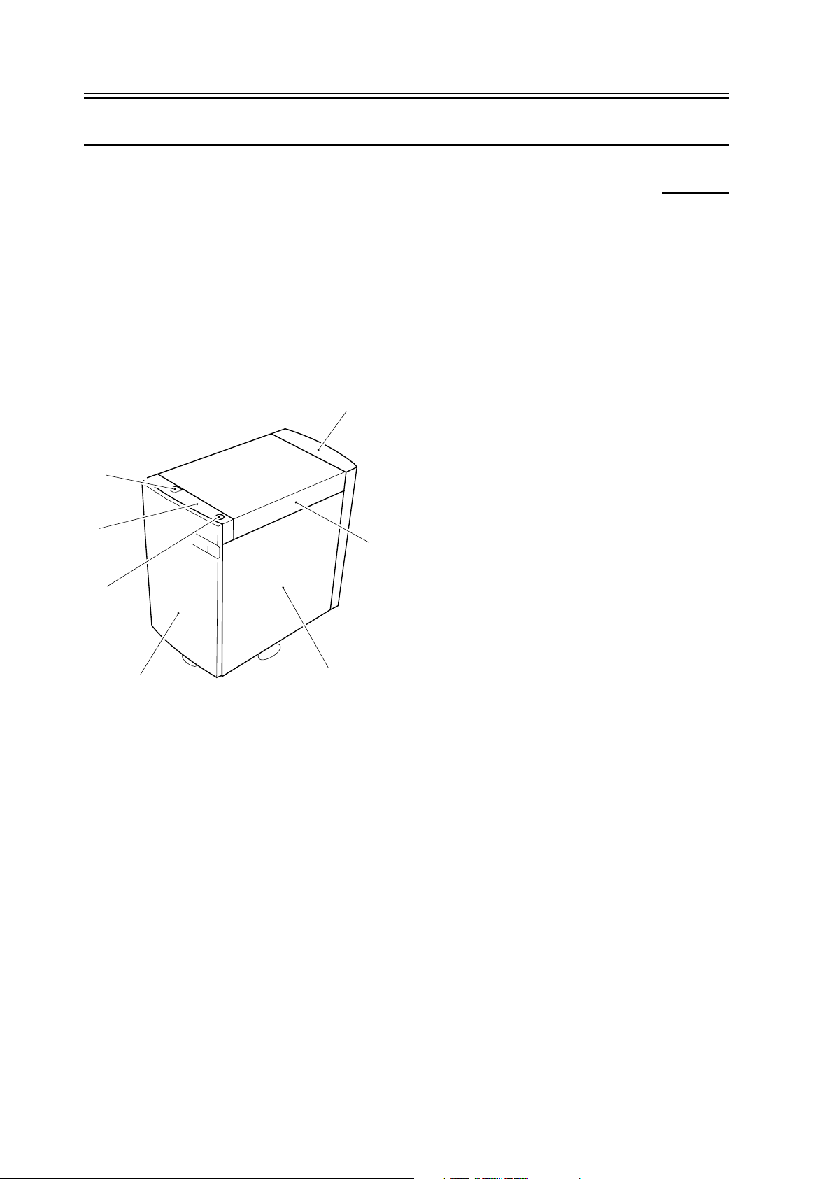
1.2.1 Names of Parts
External Covers
1 Deck release grip
2 Upper front cover
3 Compartment open/close switch
4 Front cover
5 Right cover
6 Upper cover
7 Rear cover
[1]
[2]
0003-2542
[7]
[6]
[3]
F-1-1
[4]
[5]
1-2
Page 11

Chapter 2 Functions
Page 12

Contents
Contents
2.1 Basic Construction ............................................................................................................................................2 1
2.1.1 Inputs to the Side Paper Deck (1/2)............................................................................................................ 2 1
2.1.2 Inputs to the Side Paper Deck (2/2)............................................................................................................ 2 2
2.1.3 Outputs from the Side Paper Deck (1/1) ....................................................................................................2 3
2.2 Basic Operation................................................................................................................................................. 2 4
2.2.1 Overview ....................................................................................................................................................2 4
2.2.2 Pickup Operation........................................................................................................................................ 2 4
2.2.3 Controlling the Deck Main Motor (M1D)..................................................................................................2 6
2.2.4 Controlling the Deck Lifter Motor (M2D)................................................................................................. 2 7
2.3 Paper Detection ................................................................................................................................................. 2 9
2.3.1 Detecting the Presence/Absence of Paper..................................................................................................2 9
2.3.2 Changing the Deck Paper Size................................................................................................................. 2 10
2.3.3 Detecting the Level of Paper.................................................................................................................... 2 10
2.4 Deck Lifter ......................................................................................................................................................2 11
2.4.1 Detecting the Presence/Absence of Paper................................................................................................2 11
2.5 Opening /Closing the Compartment................................................................................................................2 13
2.5.1 Opening/Closing the Compartment.......................................................................................................... 2 13
2.6 Detecting Jams ................................................................................................................................................2 15
2.6.1 Overview ..................................................................................................................................................2 15
2.7 Power Supply ..................................................................................................................................................2 16
2.7.1 Route of power supply ............................................................................................................................. 2 16
Page 13
2.1 Basic Construction
Chapter 2
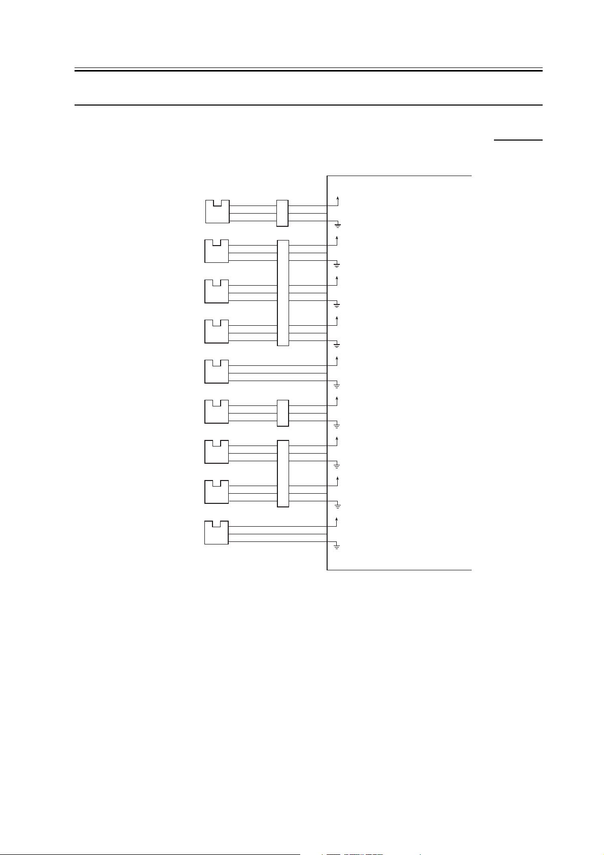
2.1.1 Inputs to the Side Paper Deck (1/2)
Deck pickup
sensor
Deck paper
absent sensor
Deck lifter upper
limit sensor
Deck lifter
position sensor
Deck set sensor
Deck feed sensor
Deck paper
supply position
Deck paper level
sensor
Deck open sensor
J10-1
PS101
PS102
PS103
PS104
J24-1
PS105
J12-1
PS106
J18-1
PS107
J19-1
PS108
J25-1
PS109
J5-1
J6-1
J7-1
J8-5
-2
-4
-3
-3
J4-4
-2
-3
-2
-3
-2
-3
-2
-3
-2
-3
-2
-3
-2
-3
-2
-3
J4-7
J4-10
J8-10
J17-3
J17-6
-3
-2
-6
-5
-9
-8
-9
-8
-2
-1
-5
-4
Side deck driver PCB
+5VR
J104-5
-4
DPPD
-3
+5VR
J103-7
-6
DPE*
-5
+5VR
J103-10
-9
DLUL
-8
+5VR
J103-13
-12
DLPD
-11
+5VR
J108-5
-4
DSET
-3
+5VR
J104-10
-9
DPFD
-8
+5VR
J107-3
-2
DPSP
-1
+5VR
J107-6
-5
DPLD
-4
+5VR
J108-8
-7
DOPND*
-6
When PS101 detects paper, '1'.
(When the light-blocking sensor is
at PS101.)
When paper is absent in the deck,
'0'.
(When the light-blocking sensor is
not at PS102.)
When the deck lifter is at the upper
limit, '1'.
(When the light-blocking sensor is
at PS103.)
When the lifter is at the pickup
position, '1'.
(When the light-blocking sensor is
at PS104.)
When the deck is set in the copier,
'1'.
(When the light-blocking sensor is
at PS105.)
When PS106 detects paper, '1'.
(When the light-blocking sensor is
at PS106.)
When the deck lifter is at the paper
supply position, '1'.
(When the light-blocking sensor is
at PS107.)
When PS108 detects the absence
of paper (level decreasing to half),
'1'.
(When the light-blocking sensor is
at PS108.)
When the compartment is set in
the deck, '1'.
(When the light-blocking sensor is
at PS109.)
0003-2548
F-2-1
2-1
Page 14
Chapter 2
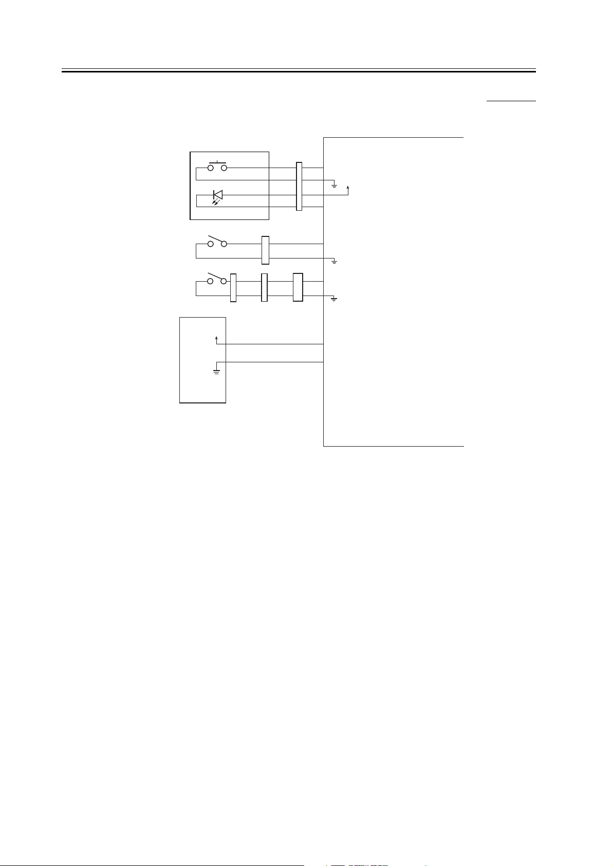
2.1.2 Inputs to the Side Paper Deck (2/2)
Deck open
switch
Deck open
indicator
Deck open
detecting switch
Deck lifter lower
limit detecting
switch
Power supply
SW100
LED100
Open switch PCB
SW101
NO
SW102
J21-1-2J20-1
NO
+24V
0VU
J2-1
J3-1
-2
-2
-3
-3
-4
-4
J26-1
-2
J17-8
-7
-3
Side deck driver PCB
J103-4
DOPN*
-3
+5VR
-2
-1
DOLON*
J109-3
DOPD*
-1
J107-8
DLLD
-7
J101-1
-2
When SW100 is pushed to open
the deck, '0'.
When the deck is open/closed,
'0'.
(The LED turns on or flashes
while the deck lifter motor is
rotating.)
When the deck is open, '0'.
(When SW101 is not pushed.)
When the deck lifter is at the
lower limit, '1'.
(When SW102 is not pushed.)
0003-2567
Copier
F-2-2
2-2
Page 15
Chapter 2
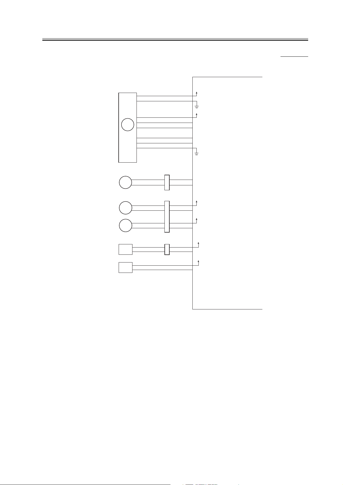
2.1.3 Outputs from the Side Paper Deck (1/1)
J106-1
J105-5
J107-9
J104-6
J104-11
Deck main
motor
Deck lifter
motor
Deck feeding
clutch
Deck pickup
clutch
M101
M102
CL101
CL102
J15-1
J22-1
J11-1
J13-2
J14-2
-2
-2
-1
-2
-6
-5
-4
-3
-1
J17-9
-10
J8-6
-7
-11
-12
Side deck driver PCB
+24VU
-2
+5VR
-1
DBIT1
-2
DBIT0
-3
DMPLK
-4
DMON
-6
-10
24VU
-7
DPFCD*
24VU
-12
DPUCD*
0003-2579
See p. 10-14.
See p. 10-16.
When '0', CL101 turns on.
When '0', CL102 turns on.
Deck pickup
roller releasing
solenoid
Deck open
solenoid
SL101
SL102
J9-2
-1
J23-2
J8-1
-2
-1
J104-1
J108-1
-2
-2
24VU
DPRSD*
24VU
DOPSD*
When '0', SL101 turns on.
When '0', SL102 turns on.
F-2-3
2-3
Page 16

Chapter 2
2.2 Basic Operation
2.2.1 Overview
The side paper deck (hereafter, "deck") is capable of accommodating as many as 3500 sheets of paper at a time (A4/
LTR/B5; 80 g/m2), ready to pick up and feed paper in response to control signals from its host machine' s DC
controller.
The lifter of the deck is driven by the deck lifter motor (M102), and the pickup operation is executed using the drive
from the deck main motor (M101).
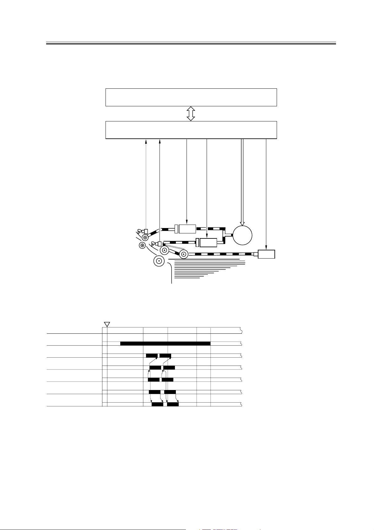
2.2.2 Pickup Operation
The paper placed in the deck is held up by the lifter at a specific point of paper pickup.
When the Start key is pressed and the deck pickup clutch (CL102) goes on, the pickup roller starts to rotate by the
drive of the deck main motor (M101), thus picking up paper. At this time, the pickup/feed roller ad the separation
roller make sure that no more that a single sheet of paper is moved ahead. Thereafter, when the deck pickup sensor
(PS101) detects the paper, the deck pickup roller release solenoid (SL101) goes on so that the pickup roller leaves
the surface of the stack of paper.
0003-2610
0003-2616
2-4
Page 17
Chapter 2
The deck feed roller starts to rotate when the deck feed clutch (CL101) goes on. The paper is then moved to the host
machine' s registration roller, where it is arched to remove any skew.
The registration roller serves to control the paper so that its leading edge will match the image on the photosensitive drum.
Deck feed paper detection
signal (DPFD)
Deck pickup detection signal
(DPPD)
PS106
PS101
DC controller PCB
Side deck driver PCB
Deck feeding clutch dive signal
(DPFCD*)
Deck pickup clutch drive signal
(DPUCD*)
CL101
CL102
(copier)
Deck pickup roller releasing
Deck main motor drive signal
M101
solenoid drive signal (DPRSD*)
SL101
Copy Start key
Deck main motor
(M101)
Deck pickup clutch
(CL102)
Deck pickup roller releasing
solenoid (SL101)
Deck pickup sensor
(PS101)
Deck feed sensor
(PS106)
Deck feeding clutch
(CL101)
F-2-5
ON
INTR
SCAN
F-2-4
PRINT
LSTR
STBY
2-5
Page 18
Chapter 2
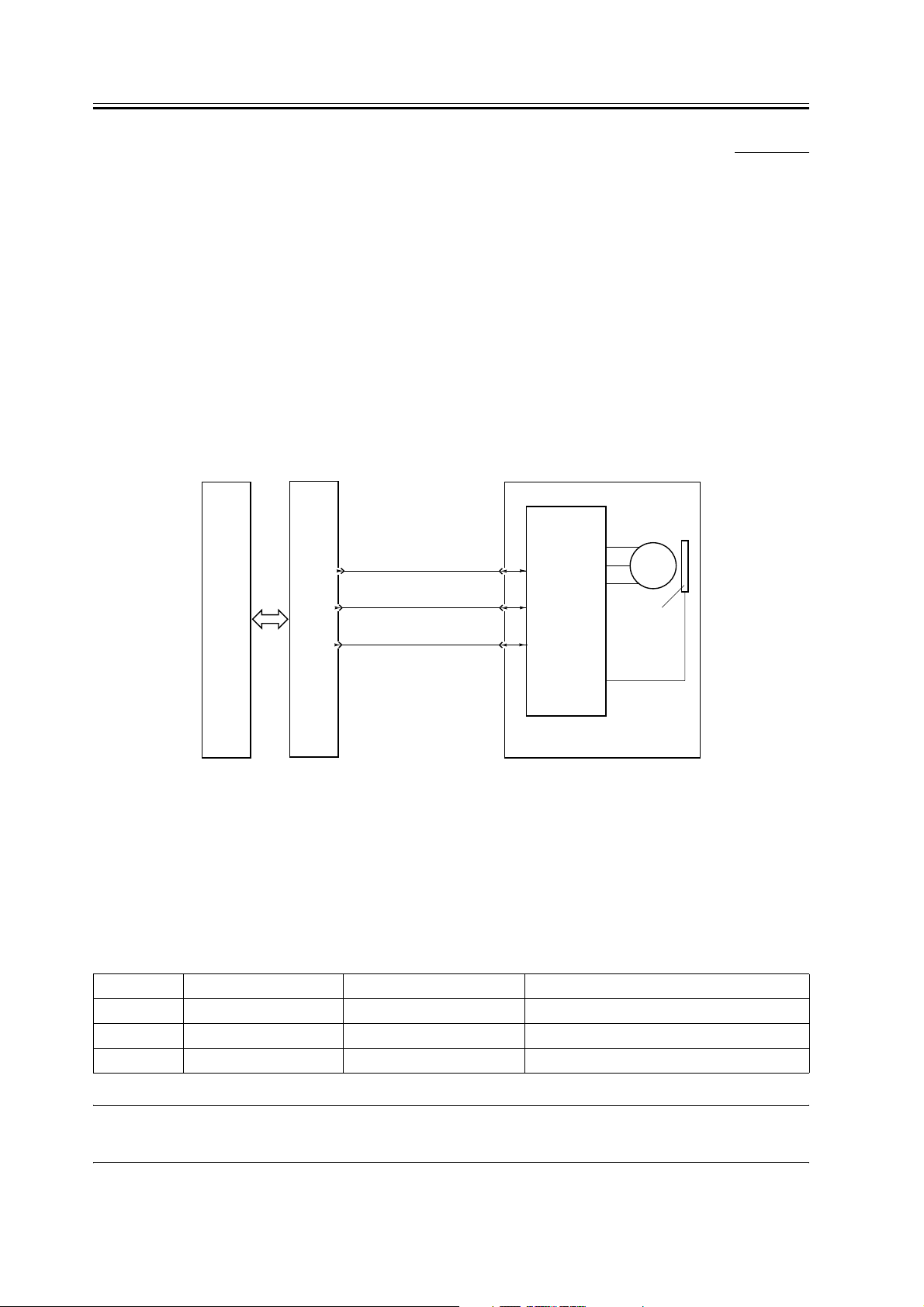
2.2.3 Controlling the Deck Main Motor (M1D)
0003-2623
1. Controlling the Deck Main Motor (M101)
The deck main motor is controlled by the host machine' s DC controller. The following diagram shows the circuit
used to drive the deck main motor, and the circuit has the following functions:
1 turns on/off the deck main motor
2 changes the speed of rotation of the deck main motor
a. Turning On/Off the Motor
When the deck main motor drive signal (DMON) from the host machine goes '1', the motor drive circuit goes on so
that the motor starts to rotate at a specific speed. When the deck main motor drive signal (DMON) goes '0' , on the
other hand, the motor drive circuit goes off to stop the motor.
The host machine' s DC controller monitors the rotation of the deck main motor with reference to the deck main
motor PULL lock signal (DMPLK); if the PULL lock signal remains '1' for 900 msec or more white DMON is '1', it
will indicate 'E043' on the host machine' s control panel.
Deck main motor
Deck main motor drive
DC
controller
PCB
Side
deck
driver
PCB
J105
signal (DMON)
-4
Deck main motor PLL
-3
lock signal (DMPLK)
Deck main motor speed
-2
switch signal (DBIT 0)
J14
-3
-4
-5
Motor
drive circuit
M101
Encoder
(copier)
Deck main motor driver PCB
F-2-6
b. Changing the Speed of Rotation of the Motor
The deck is designed to automatically change the speed of pickup so as to support future host machines. The pickup
speed is changed in response to external clock signals (MOTOR CLK) that are sent by the host machine' s DC
controller to the side deck drive PCB in keeping with the speed of motor rotation. The relationship between the speed
of motor rotation and the frequency of the external clock signals is as follows:
T-2-1
Drive speed Rotation of motor shaft External clock setting (Hz) Drive mode
Speed 1 2885.93 1443 used when picking up plain paper
Speed 2 2308.80 1155 used when picking up H/H color (PS)
Speed 3 1847.05 924 used when picking up heavy paper (1/3 PS)
MEMO
When making color copies/prints, the drive speed is shifted to speed 2 or 3.
2-6
Page 19

Chapter 2
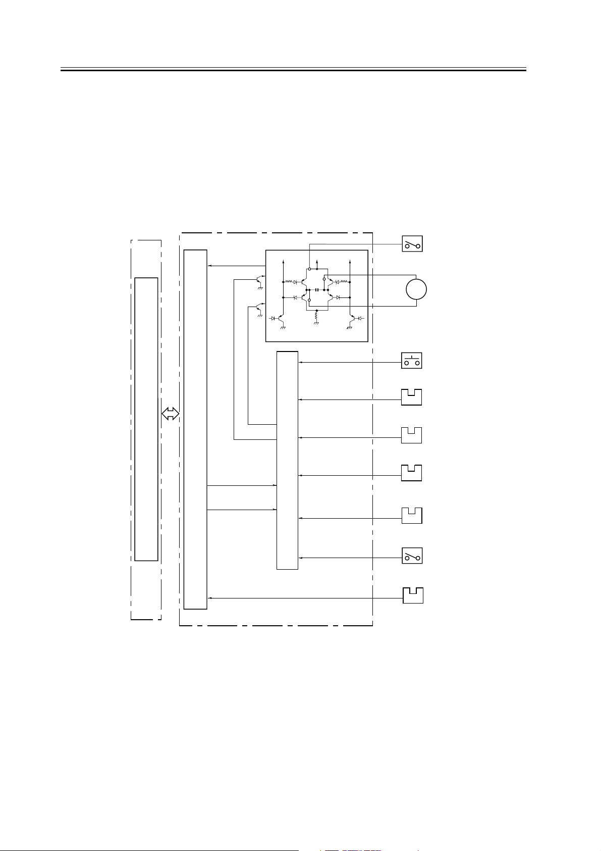
2.2.4 Controlling the Deck Lifter Motor (M2D)
2. Controlling the Deck Lifter Motor (M102)
The deck lifter motor control circuit is found as part of the side deck driver PCB. The following is a block diagram
of the circuit:
The combination circuit shown in the diagram consists of various logic circuits, and the deck lifter motor is rotated
in normal or reverse direction using combinations of the deck lifter drive signal (DLMON*) and the deck lifer ascent
signal (DLUP*) from the host machine' s DC controller and the output signals of various sensors.
If, for some reason, the deck lifter position sensor (PS104) does not detect the lifter within 60 sec after the deck lifter
ascent signal is generated, an error code (E041) will be indicated on the host machine' s control panel.
1 Conditions Used to Move Up the Lifter
the deck is joined with its host machine, i.e., the deck set signal (DSET) is '1'.
the deck (compartment) is closed, i.e., the deck open detection signal (DOPND*) is '1'.
the deck (compartment) is closed, i.e., the deck open detecting switch is 'on'.
the deck lifter upper limit signal (DLUL) is '0' and, in addition, the deck lifter position detecting signal (DLPD) is '0'.
the deck lifer motor drive signal (DLMON*) is '0'.
the deck lifter ascent signal (DLUP* is '0'.
In the presence of these conditions, the lifter starts to move up.
0003-2639
2-7
Page 20
Chapter 2
2 Conditions Used to Move Down the Lifter
the deck (compartment) is open, i.e., the deck open detection signal (DOPND*) is '0'.
the deck lower limit detection signal (DLLD) is '0' and, in addition, the deck lifter position detection signal (DLPD)
is '0'.
the deck lifter motor drive signal (DLMON*) is '0'.
the deck lifter ascent signal (DLUP*) is '1'.
In the presence of these conditions, the lifter starts to move down.
Deck open
detection signal
(DOPD)
Deck lifter up drive signal
Deck lifter motor down signal
DC controller PCB
Deck lifter motor
drive signal
(DLMON*)
Communication conversion IC (Q17)
Deck lifter up
signal (DLUP*)
Deck paper supply position detection signal (DPSP)
Copier
Note: The communications conversion IC (Q17) in the diagram converts
serial signals to parallel signals and vice versa.
24V
24V
Motor drive circuit
Deck open signal
(DOPN*)
Deck lifter upper limit
detection signal
(DLUL)
Deck open detection
signal (DOPND*)
Deck lifter position
detection signal
(DLPD)
Combination circuit
Deck set signal
(DSET)
Deck lifter roller limit
detection signal
(DLLD)
Side deck driver PCB
24V
Deck open detecting
switch (SW101)
M102
Deck lifter
motor
Deck open
switch (SW100)
PS103
Deck lifter upper
limit sensor
PS109
Deck open
sensor
PS104
Deck lifter
position sensor
PS105
Deck set
sensor
Deck lifter lower limit
detecting switch (SW102)
PS107
Deck paper supply
position sensor
F-2-7
2-8
Page 21
2.3 Paper Detection
Chapter 2
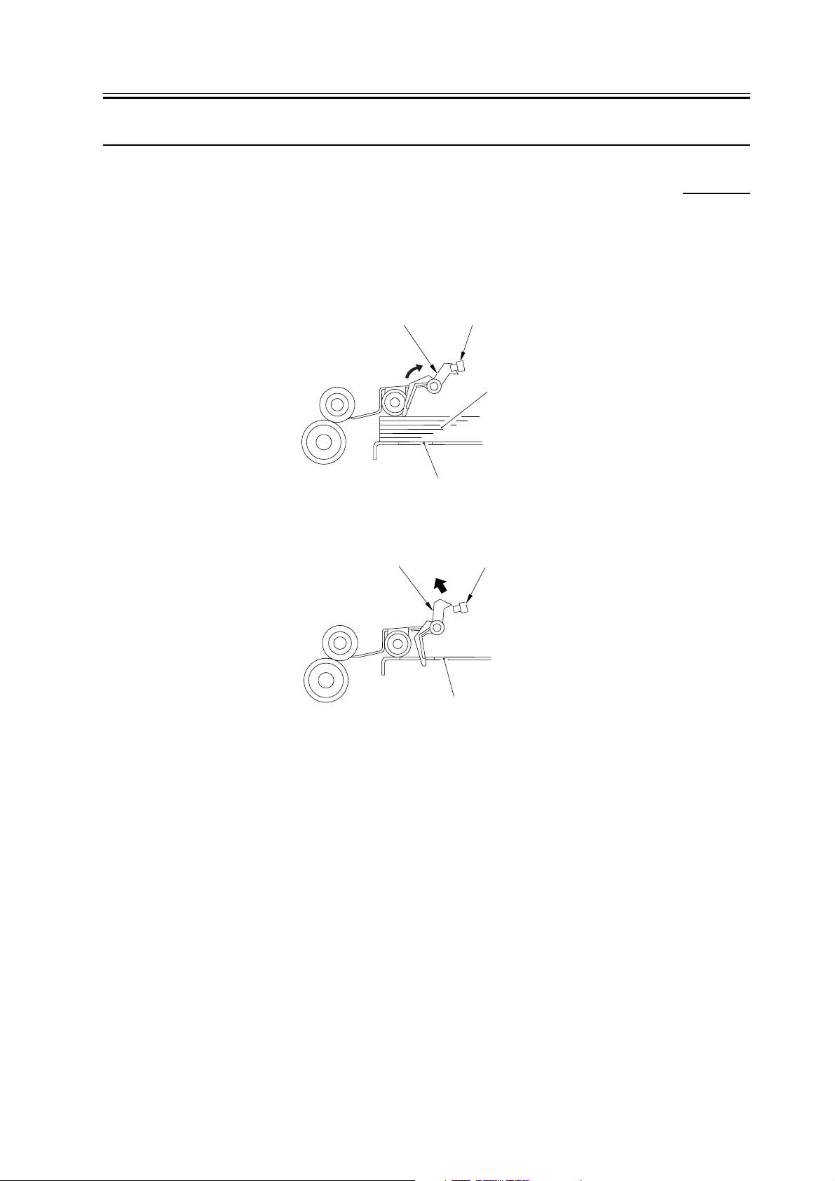
2.3.1 Detecting the Presence/Absence of Paper
0003-2817
1. Detecting the Presence/Absence of Paper
The presence/absence of paper inside the deck is checked by the deck paper sensor (PS102). When paper runs out
and the paper detecting lever of the pickup roller assembly leaves the deck paper sensor, the host machine indicates
the absence of paper on its control panel.
Paper detecting lever
Deck paper absent sensor
Copy paper
Lifter
F-2-8
Paper detecting lever
Deck paper absent sensor
F-2-9
Lifter
2-9
Page 22

Chapter 2
2.3.2 Changing the Deck Paper Size
2. Changing the Deck Paper Size
To change the paper size of the deck, you must move the guide plate in the deck to suit the user' s needs and then
select the correct paper size in service mode: OPTION>ACC>DKP.
2.3.3 Detecting the Level of Paper
3. Detecting the Level of Paper in the Deck
The deck uses the deck paper supply position sensor (PS107), deck paper level sensor (PS108), and deck paper
sensor (PS102) to check the level of paper inside its compartment; the result of the check is indicated on the host
machine' s control panel. The following table shows how a check is made with reference to the states of the sensors:
T-2-2
paper level PS102 PS107 PS108
about 1750 to 3500 sheets 1 1 1
about 500 to 1750 sheets 1 1 0
0003-2666
0003-2669
1 to about 500 sheetssheets 1 0 0
no paper 0 0 0
1: the lightblocking plate is over the sensor.
0: the lightblocking plate is not over the sensor.
2-10
Page 23

2.4 Deck Lifter
Chapter 2
2.4.1 Detecting the Presence/Absence of Paper
The lifter of the deck is joined to a reel by means of a cable, and is driven by the deck lifter motor (M102); i.e., the
lifter moves up or down depending on the direction of rotation of the motor.
When the deck (compartment) is pushed inside the host machine, the deck open detecting switch (SW101) is pushed.
The lifter starts to move up as soon as the deck open sensor (PS109) detects the lightblocking plate; the lifter stops
to move up when the deck position sensor (PS104) detects the top of the stack of paper placed on the lifter
In the rare event that the lifter should fail to stop moving up after the sensor lever blocks the deck lifter position sensor
for some reason, the deck lifter upper limit sensor (PS103) will go on to stop the lifter, thereby preventing damage
to the deck.
The lifter, on the other hand, starts to move down when the deck open switch (SCREW100) is pushed, and will keep
moving down until the lifter moves past the sensor lever of the deck paper supply position sensor (PS107), i.e., falling
edge of the sensor output.
The addition of paper in this condition will push the lever of the deck paper supply position sensor, causing the lifter
to move farther down until the stack of paper moves past the sensor lever.
The lifter repeats its descent operation each time paper is added until the deck lifter lower limit detecting switch
(SW102) is pushed (maximum paper supply position).
0003-2819
2-11
Page 24

Chapter 2
The host machine' s DC CPU monitors the timing at which sensors associated with deck lifter operation go on; and,
if the deck paper supply position sensor (PS107) is '0' when the deck lifter position sensor (PS104) and the deck level
sensor (PS108) are '1' (not a normal combination), it will indicate an error code (E041) on the host machine' s control
panel.
Deck lifter
position sensor
(PS104)
Deck lifter upper
limit sensor
(PS103)
Deck pickup / feeding roller
Deck open
switch
(SW100)
Deck main
motor
Deck paper
level sensor
(PS108)
Deck open
detection switch
(SW101)
M101
Deck paper
supply position sensor
(PS107)
Deck pickup roller
M102
Deck lifter
motor
Deck lifter lower
limit detecting switch
(SW102)
Deck separation roller
Deck lifter
cable
Lifter
Copy paper
F-2-10
2-12
Page 25

2.5 Opening /Closing the Compartment
Chapter 2
2.5.1 Opening/Closing the Compartment
0003-2823
1. Opening/Closing the Deck
When the deck open switch (SW100) is pushed, the deck open solenoid (SL102) goes on to free the lock on the deck
(compartment); as a result, the deck is pushed several centimeters to the front by the work of a spring. At the same
time, the deck lifter motor (M102) starts to rotate to move down the lifter inside the deck.
When the deck (compartment) is pushed into the host machine, the deck open sensor (PS109) detects the light
blocking plate, permitting the lifter to move up as far as the pickup position.
When the deck lifter motor rotates to open/close the deck, the deck open indicator (LED100) on the open switch PCB
goes on or flashes.
J100
-1
SW100
-4
LED100
Open switch PCB
(compartment)
Deck lifter
Deck open signal (DOPN*)
Deck open indicator LED activation signal (DOLON*)
Deck lifter upper limit detection signal
PS103
(DLUL)
PS109
Deck open detecting signal (DOPND*)
SW101
Deck open detection signal (DOPD*)
J103
- 4
J103
- 1
J103
- 9
J108
- 7
J109
- 3
Side
deck
driver
PCB
DC
controller
PCB
Open
SW102
M102
Deck open solenoid drive signal
(DOPSD*)
SL102
Deck lifter lower limit detection signal
(DLLD)
Deck lifter motor drive signal
F-2-11
J108
-11
J107
- 8
J107
(copier)
2-13
Page 26

Chapter 2
2. Sequence of Operation Used to Open/Close the Deck.
Deck open
switch ON
Compartment set
Deck open indicator
(LED100)
Deck lifter motor
(M102)
Deck paper supply position
sensor (PS107)
Deck lifter lower limit
detecting switch (SW102)
Deck open solenoid
(SL102)
Deck open detecting switch
(SW101)
Deck open sensor
(PS109)
Deck lifter position sensor
(PS104)
Flashing On
Flashing
**
Compartment open
Deck lifter down Deck lifter up
* : Varies according to the level of the stack.
F-2-12
Off
2-14
Page 27

2.6 Detecting Jams
Chapter 2
2.6.1 Overview
0003-2825
The side paper deck is equipped with the following 2 sensors used to find out whether or not paper is moving
smoothly. The machine checks for the presence of a jam at such times as initiated its DC controller PCB and with
reference to the signals from these sensors. When the machine's DC controller PCB identifies a jam, it discharges
sheets ahead of the jam and stops the ongoing operation, after which it will indicate jam removal instructions on its
control panel.
T-2-3
Sensor No. Name Principal function
PS106 deck feed sensor detecting delay jams
PS101 deck pickup sensor detecting delay jams
1. when the machine's power switch is turned on or at the end of the waitup period or during standby, the presence
of paper is detected over the deck feed sensor (PS106).
2. deck pickup/vertical path delay jam
Copy Start key
Deck pickup clutch
(CL102)
Jam check
Deck pickup sensor
(PS101)
Deck feed sensor
(PS106)
Deck main motor
(M101)
ON
INTR
Jam indicator
SCAN
Normal Error
PRINT
F-2-13
2-15
Page 28

Chapter 2
2.7 Power Supply
2.7.1 Route of power supply
[1]
0003-2834
[2]
F-2-14
[1] Side deck I/F cable
[2] Side deck heater cable
2-16
Page 29

Chapter 3 Parts
Replacement
Procedure
Page 30

Contents
Contents
3.1 Removing from the Host Machine.................................................................................................................... 3 1
3.1.1 Compartment..............................................................................................................................................3 1
3.1.1.1 Removing the Compartment................................................................................................................ 3 1
3.1.2 Paper Deck .................................................................................................................................................3 2
3.1.2.1 Detaching from the Host Machin........................................................................................................3 2
3.1.2.2 Opening the Compartment ..................................................................................................................3 2
3.1.2.3 Removing the Right Cover.................................................................................................................. 3 2
3.1.2.4 Detaching the Deck from the Host Machine....................................................................................... 3 3
3.2 External Covers................................................................................................................................................. 3 3
3.2.1 Front Cover................................................................................................................................................. 3 3
3.2.1.1 Opening the Compartment ..................................................................................................................3 3
3.2.1.2 Removing the Front Cover.................................................................................................................. 3 3
3.2.2 Rear Cover.................................................................................................................................................. 3 4
3.2.2.1 Removing the Rear Cover................................................................................................................... 3 4
3.2.3 Right Cover ................................................................................................................................................ 3 4
3.2.3.1 Opening the Compartment ..................................................................................................................3 4
3.2.3.2 Removing the Right Cover.................................................................................................................. 3 4
3.2.4 Upper Cover ............................................................................................................................................... 3 5
3.2.4.1 Removing the Rear Cover................................................................................................................... 3 5
3.2.4.2 Opening the Compartment ..................................................................................................................3 5
3.2.4.3 Removing the Upper Front Cover....................................................................................................... 3 5
3.2.4.4 Removing the Upper Cover................................................................................................................. 3 5
3.3 Drive System ..................................................................................................................................................... 3 6
3.3.1 Deck Pickup Clutch.................................................................................................................................... 3 6
3.3.1.1 Removing the Rear Cover................................................................................................................... 3 6
3.3.1.2 Opening the Compartment ..................................................................................................................3 6
3.3.1.3 Removing the Upper Front Cover....................................................................................................... 3 6
3.3.1.4 Removing the Upper Cover................................................................................................................. 3 6
3.3.1.5 Removing the Pickup Unit .................................................................................................................. 3 7
3.3.1.6 Removing the Pickup Clutch............................................................................................................... 3 7
3.3.2 Deck Feed Clutch....................................................................................................................................... 3 7
3.3.2.1 Removing the Rear Cover................................................................................................................... 3 7
3.3.2.2 Opening the Compartment ..................................................................................................................3 8
3.3.2.3 Removing the Upper Front Cover....................................................................................................... 3 8
3.3.2.4 Removing the Upper Cover................................................................................................................. 3 8
3.3.2.5 Removing the Pickup Unit .................................................................................................................. 3 8
3.3.2.6 Removing the Feed Clutch.................................................................................................................. 3 9
3.3.3 Deck Main Motor .......................................................................................................................................3 9
3.3.3.1 Removing the Rear Cover................................................................................................................... 3 9
3.3.3.2 Removing the Deck Main Motor (M101) ........................................................................................... 3 9
3.3.4 Deck Lifter Motor .................................................................................................................................... 3 10
3.3.4.1 Opening the Compartment ................................................................................................................ 3 10
3.3.4.2 Positioning the Deck Lifter ...............................................................................................................3 10
3.3.4.3 Removing the Compartment.............................................................................................................. 3 11
3.3.4.4 Removing the Deck Lifter Motor (M2D)..........................................................................................3 12
3.3.5 Lifter Cable (Front) .................................................................................................................................. 3 13
3.3.5.1 Opening the Compartment ................................................................................................................ 3 13
3.3.5.2 Removing the Lifter Cable (deck front)............................................................................................3 13
3.3.5.3 Stringing the Lifter Cable.................................................................................................................. 3 14
Page 31

3.3.6 Lifter Cable...............................................................................................................................................3 15
3.3.6.1 Opening the Compartment.................................................................................................................3 15
3.3.6.2 Removing the Compartment..............................................................................................................3 15
3.3.6.3 Removing the Lifter Cable (deck rear)..............................................................................................3 16
3.3.6.4 Stringing the Lifter Cable..................................................................................................................3 17
3.4 Document Feeding System..............................................................................................................................3 18
3.4.1 Deck Pickup Unit......................................................................................................................................3 18
3.4.1.1 Removing the Rear Cover..................................................................................................................3 18
3.4.1.2 Opening the Compartment.................................................................................................................3 18
3.4.1.3 Removing the Upper Front Cover .....................................................................................................3 18
3.4.1.4 Removing the Upper Cover...............................................................................................................3 18
3.4.1.5 Removing the Deck Pickup Unit.......................................................................................................3 19
3.4.2 Deck Pickup Roller...................................................................................................................................3 19
3.4.2.1 Removing the Rear Cover..................................................................................................................3 19
3.4.2.2 Opening the Compartment.................................................................................................................3 19
3.4.2.3 Removing the Upper Front Cover .....................................................................................................3 20
3.4.2.4 Removing the Upper Cover...............................................................................................................3 20
3.4.2.5 Removing the Deck Pickup Unit.......................................................................................................3 20
3.4.2.6 Removing the Deck Pickup Roller ....................................................................................................3 21
3.4.2.7 Points to Note When Mounting the Deck Pickup Roller...................................................................3 21
3.4.3 Deck Pickup/Feed Roller..........................................................................................................................3 22
3.4.3.1 Removing the Rear Cover..................................................................................................................3 22
3.4.3.2 Opening the Compartment.................................................................................................................3 22
3.4.3.3 Removing the Upper Front Cover .....................................................................................................3 22
3.4.3.4 Removing the Upper Cover...............................................................................................................3 22
3.4.3.5 Removing the Deck Pickup Unit.......................................................................................................3 23
3.4.3.6 Removing the Deck Pickup/Feed Roller ...........................................................................................3 23
3.4.3.7 Points to Note When Mounting the Deck Pickup/Feed Roller..........................................................3 23
3.4.4 Deck Separation Roller.............................................................................................................................3 24
3.4.4.1 Removing the Deck Separation Roller ..............................................................................................3 24
3.5 Electrical System .............................................................................................................................................3 25
3.5.1 Deck Driver PCB......................................................................................................................................3 25
3.5.1.1 Removing the Rear Cover..................................................................................................................3 25
3.5.1.2 Removing the Deck Driver PCB .......................................................................................................3 25
3.5.2 Open Switch PCB.....................................................................................................................................3 25
3.5.2.1 Opening the Compartment.................................................................................................................3 25
3.5.2.2 Removing the Upper Front Cover .....................................................................................................3 26
3.5.2.3 Removing the Open Switch PCB.......................................................................................................3 26
Page 32

Chapter 3
3.1 Removing from the Host
Machine
3.1.1 Compartment
3.1.1.1 Removing the
Compartment
1) Place a stack of paper [3] (about 8 cm in height) on
the floor on which to place the deck [2], thus
preventing damage to the roll support plate [1].
[2]
[3]
[1]
F-3-1
2) Push the deck release grip [1] to detach the deck
from its host machine; then, push down the latch
plate [2] found at the rear left to open the
compartment.
[3]
0003-8452
A
3) Remove the 3 screws [1], and detach the right cover
[2].
[2]
[1]
F-3-3
4) Remove the screw [1] of the harness guide,
disconnect the connector [2], and remove the 3 screws
each on the right and left of the compartment rail [3];
then, lift the compartment [5] slightly to detach it
toward the front.
[1]
[4]
(rear)
F-3-2
[1]
[2]
[2]
[4]
[3]
[5]
F-3-4
5) Place the compartment [5] on the base you prepared
in step 1).
3-1
Page 33

Chapter 3
3.1.2 Paper Deck
3.1.2.1 Detaching from the
Host Machin
1) Place a stack of sheets [3] (A: about 8 cm in height)
on the floor on which to place the deck [2], thus
preventing the deformation of the roll support plate
[1].
[2]
[3]
[1]
F-3-5
[3]
0003-2842
A
3.1.2.2 Opening the
Compartment
1) Push the deck release grip [1] to detach the deck
from its host machine. Then, push down the latch
plate [2] found at the rear left to open the
compartment.
[1]
(rear)
[2]
F-3-6
0003-2941
3.1.2.3 Removing the Right
Cover
0003-2906
1) Detach the deck from its host machine; then,
remove the 3 screws [1], and detach the right cover
[2].
[2]
[1]
F-3-7
3-2
Page 34

Chapter 3
3.1.2.4 Detaching the Deck
from the Host Machine
1) Remove the 4 screws [1], and detach the deck [2]
from the deck base [3].
[2]
(left)
F-3-8
[3]
[1]
0003-2907
3.2 External Covers
3.2.1 Front Cover
3.2.1.1 Opening the
Compartment
1) Push the deck release grip [1] to detach the deck
from its host machine. Then, push down the latch
plate [2] found at the rear left to open the
compartment.
[1]
0003-2937
(right)
[1]
F-3-9
2) Hold the deck by the locations indicated in the
figure; then, lift the deck [4], and place it on the base
you prepared in "Detaching from the Host Machine".
(rear)
[2]
F-3-11
3.2.1.2 Removing the Front
Cover
1) Loosen the 4 screws [1], and detach the front cover
[2] of the deck toward the front.
[1]
0003-2848
F-3-10
[4]
[2]
F-3-12
3-3
Page 35

Chapter 3
Be sure to mount the front cover so that the gap
between the front over and the upper front cover is 3
+/1 mm.
Upper front cover
3.2.3 Right Cover
3.2.3.1 Opening the
Compartment
1) Push the deck release grip [1] to detach the deck
from its host machine. Then, push down the latch
plate [2] found at the rear left to open the
compartment.
0003-9073
Front cover
m
m
1
±
3
F-3-13
3.2.2 Rear Cover
3.2.2.1 Removing the Rear
Cover
1) Detach the deck from its host machine; then,
remove the 6 screws [1], and detach the rear cover [2].
[1]
0003-2852
[1]
(rear)
[2]
F-3-15
3.2.3.2 Removing the Right
Cover
1) Detach the deck from its host machine; then,
remove the 3 screws [1], and detach the right cover
[2].
[2]
0003-2866
[2]
F-3-14
3-4
[1]
[1]
[1]
F-3-16
Page 36

Chapter 3
3.2.4 Upper Cover
3.2.4.1 Removing the Rear
Cover
1) Detach the deck from its host machine; then,
remove the 6 screws [1], and detach the rear cover [2].
[1]
[1]
[2]
0003-2910
3.2.4.3 Removing the Upper
Front Cover
1) Remove the 3 screws [1], and disconnect the
connector [2]; then, detach the upper front cover [3].
[1]
F-3-19
[2]
0003-2926
[3]
3.2.4.4 Removing the Upper
Cover
0003-2868
[1]
F-3-17
3.2.4.2 Opening the
Compartment
1) Push the deck release grip [1] to detach the deck
from its host machine. Then, push down the latch
plate [2] found at the rear left to open the
compartment.
[1]
(rear)
0003-2939
1) Remove the 2 screws [1], and detach the upper
cover [2].
[1]
[2]
F-3-20
F-3-18
[2]
3-5
Page 37

Chapter 3
3.3 Drive System
3.3.1 Deck Pickup Clutch
3.3.1.1 Removing the Rear
Cover
1) Detach the deck from its host machine; then,
remove the 6 screws [1], and detach the rear cover [2].
[1]
[1]
[2]
0003-2929
3.3.1.3 Removing the Upper
Front Cover
1) Remove the 3 screws [1], and disconnect the
connector [2]; then, detach the upper front cover [3].
[1]
F-3-23
[2]
0003-2931
[3]
3.3.1.4 Removing the Upper
Cover
0003-2932
[1]
F-3-21
3.3.1.2 Opening the
Compartment
1) Push the deck release grip [1] to detach the deck
from its host machine. Then, push down the latch
plate [2] found at the rear left to open the
compartment.
[1]
0003-2940
1) Remove the 2 screws [1], and detach the upper
cover [2].
[1]
[2]
F-3-24
(rear)
F-3-22
3-6
[2]
Page 38

Chapter 3
3.3.1.5 Removing the Pickup
Unit
1) Disconnect the 2 connectors [1], and remove the 5
screws [2]; then, detach the deck pickup unit [3].
[1]
[2]
[2]
F-3-25
When mounting the deck pickup unit [3], be sure
to tighten the 3 screws shown in the figure first.
[3]
0003-8509
[2]
3.3.1.6 Removing the Pickup
Clutch
1) Disconnect the connector [1], and remove the E
ring [2]; then, detach the deck pickup clutch [3].
[1]
[3]
[4]
F-3-27
When mounting the pickup clutch, be sure that the
clutch is fitted in the stop [4].
Moreover, be sure that the harness is hooked on the U
groove [5] of the guide.
[2]
[5]
0003-2934
F-3-26
Screws
[3]
3.3.2 Deck Feed Clutch
3.3.2.1 Removing the Rear
Cover
1) Detach the deck from its host machine; then,
remove the 6 screws [1], and detach the rear cover [2].
[1]
[1]
[2]
0003-2936
F-3-28
[1]
3-7
Page 39

Chapter 3
3.3.2.2 Opening the
Compartment
1) Push the deck release grip [1] to detach the deck
from its host machine. Then, push down the latch
plate [2] found at the rear left to open the
compartment.
[1]
(rear)
[2]
F-3-29
0003-2943
3.3.2.3 Removing the Upper
3.3.2.4 Removing the Upper
Cover
1) Remove the 2 screws [1], and detach the upper
cover [2].
[1]
F-3-31
0003-2945
[2]
3.3.2.5 Removing the Pickup
Unit
1) Disconnect the 2 connectors [1], and remove the 5
screws [2]; then, detach the deck pickup unit [3].
0003-8508
Front Cover
0003-2944
1) Remove the 3 screws [1], and disconnect the
connector [2]; then, detach the upper front cover [3].
[1]
[2]
[3]
F-3-30
[2]
[1]
[2]
F-3-32
[3]
[2]
3-8
Page 40

When mounting the deck pickup unit [3], be sure
to tighten the 3 screws shown in the figure first.
Chapter 3
3.3.3 Deck Main Motor
3.3.3.1 Removing the Rear
[3]
Screws
F-3-33
3.3.2.6 Removing the Feed
Clutch
1) Remove the harness retainer [1], disconnect the
connector [2], and remove the Ering [3]; then, detach
the deck feed clutch [4].
0003-2948
Cover
0003-8453
1) Detach the deck from its host machine; then,
remove the 6 screws [1], and detach the rear cover [2].
[1]
[1]
[2]
[1]
F-3-35
[1]
[3]
[4]
[2]
[5]
F-3-34
When mounting the feed clutch, be sure that the
clutch is fitted in the stop [5].
3.3.3.2 Removing the Deck
Main Motor (M101)
1) Disconnect the 2 connectors [1], and remove the 4
screws [2]; then, detach the deck main motor [3]. At
this time, be sure to take care not to damage the gear
found at the tip of the motor spindle.
[2]
[1]
[3]
F-3-36
0003-8454
3-9
Page 41

Chapter 3
3.3.4 Deck Lifter Motor
3.3.4.1 Opening the
Compartment
1) Push the deck release grip [1] to detach the deck
from its host machine. Then, push down the latch
plate [2] found at the rear left to open the
compartment.
[1]
(rear)
[2]
F-3-37
0003-8466
3.3.4.2 Positioning the Deck
Lifter
1) If there is any paper, remove all.
2) Turn on the host machine's power switch.
3) If the deck lifter is in its up position, move it so that
the distance A from the bottom plate of the
compartment of the deck lifter is about 7 cm. Push
the sensor flag [2] of the paper supply position
sensor found inside the compartment [1] so that the
deck lifter moves down. (The deck lifter will stop as
soon as you release the flag.)
Insert a hex wrench [3] into the hole of the lifter drive
shaft [4] to fix it in place (against turning).
[1]
0003-8468
[2]
F-3-38
[3]
[4]
7 cm (approx.)
F-3-39
4) Connect the power plug, and turn on the host
machine's power switch.
3-10
Page 42

Chapter 3
3.3.4.3 Removing the
Compartment
1) Place a stack of paper [3] (about 8 cm in height) on
the floor on which to place the deck [2], thus
preventing damage to the roll support plate [1].
0003-9101
[2]
8 cm (approx.)
3) Remove the screw [1] and the stopper plate [2];
then, slide father out the compartment [3].
[2]
(rear left of the
compartment)
[1]
[3]
F-3-42
4) Remove the 3 screws [1], and detach the right cover
[2].
[3]
[1]
[3]
F-3-40
2) Push the deck release grip [1] to detach the deck
from its host machine; then, push down the latch
plate [2] found at the rear left to open the
compartment.
[1]
(rear)
[2]
F-3-41
[2]
[1]
F-3-43
3-11
Page 43

Chapter 3
5) Remove the screw [1] of the harness guide,
disconnect the connector [2], and remove the 3 screws
each on the right and left of the compartment rail [3];
then, lift the compartment [5] slightly to detach it
toward the front.
[1]
[2]
[4]
[4]
[3]
[5]
F-3-44
6) Place the compartment [5] on the base you prepared
in step 1).
3.3.4.4 Removing the Deck
Lifter Motor (M2D)
1) Disconnect the connector [1], and remove the 5
screws [2]; then, detach the deck lifter motor unit
[3].
[1]
[2]
[3]
F-3-45
0003-8470
[2]
3-12
Page 44

Chapter 3
3.3.5 Lifter Cable (Front)
3.3.5.1 Opening the
Compartment
1) Push the deck release grip [1] to detach the deck
from its host machine. Then, push down the latch
plate [2] found at the rear left to open the
compartment.
[1]
(rear)
[2]
F-3-46
0003-8472
Push the flag [2] of the paper position sensor found
inside the compartment [3] until the deck lifter
comes into contact with the screwdrivers.
(The deck lifter will stop when you let go of the flag.)
[1]
[3]
[2]
F-3-47
3.3.5.2 Removing the Lifter
Cable (deck front)
1) If there is any paper, remove all.
2) Insert 2 long screwdrivers [1] to keep the lifter in
position.
3) So that the left and right holes of the compartment
side plate and the left and right holes of the lifter
will match, move down the lifter by pushing the
flag [1] of the paper supply position sensor.
Connect the power plug, and turn on the host
machine's power switch.
0003-8473
4) Loosen the 4 screws [1], and detach the front cover
[2].
Do not remove the screws.
[1]
[2]
F-3-48
3-13
Page 45

Chapter 3
Use the 4 screws used to keep the front cover in
place when adjusting the position of the front cover
so that the gap A between the front cover and the
upper front cover is 3 +/1 mm.
Upper front cover
Front cover
m
m
1
±
3
F-3-49
5) Remove the 4 screws [1], and detach the roll
support plate [2].
[1]
8) Remove the 2 screws [7], and detach the right cable
fixing plate [8]; then, detach the inside lifter cable
[9].
9) Remove the 2 set screws [12] and detach the
outside pulley [11] to detach the inside lifter cable
[9] from the inside pulley [10].
[12] [6] [9]
[4] [5] [10][11] [8] [7]
[2]
F-3-50
6) Remove the coupling shaft [1] and the Ering [2];
then, detach the pulley cover [3].
7) Remove the 2 screws [4], and detach the left cable
fixing plate [5]; then, detach the outside lifter cable
[6].
[3]
[2]
[1]
F-3-51
3.3.5.3 Stringing the Lifter
Cable
1) Check to make sure that the lifter drive shaft [1] and
the lifter [2] are fixed in place using a hex wrench
[3] and 2 long screwdrivers [4], respectively.
2) Fix the 4 cable fixing plates [5] in place to the lifter
using 2 screws each.
3) Hook the lifer cable [6] on the 4 pulleys [7] above.
4) Hook the ball of the lifter cable on the 2 front/rear
pulleys [8] of the lifter drive shaft; then, wind it
about 1.5 times along the groove of the pulley.
At this time, be sure to keep the lifter cable taut so that
the long drivers used to keep the lifter are slightly
lifted by the cable.
0003-8479
3-14
Page 46

Chapter 3
5) Fix the 2 pulleys [5] in place to the lifter drive shaft
with a set screw [9] (1 pc. each).
6) Fit all removed pulleys to the lifter shaft; then,
measure the height A from the base plate of the
compartment to the top face of the lifter, thus
making sure that the lifter is level.
[7]
[5]
[1]
[7]
[8]
[6]
[A]
[5]
[9]
[8]
[3]
[5]
[A]
[A]
[9]
[5]
[A]
[2]
[4]
F-3-52
3.3.6 Lifter Cable
3.3.6.2 Removing the
Compartment
1) Place a stack of paper [3] (about 8 cm in height) on
the floor on which to place the deck [2], thus
preventing damage to the roll support plate [1].
0003-9131
[2]
8 cm (approx.)
[3]
F-3-54
[1]
[3]
3.3.6.1 Opening the
Compartment
1) Push the deck release grip [1] to detach the deck
from its host machine. Then, push down the latch
plate [2] found at the rear left to open the
compartment.
[1]
(rear)
[2]
F-3-53
0003-8480
2) Push the deck release grip [1] to detach the deck
from its host machine; then, push down the latch
plate [2] found at the rear left to open the
compartment.
[1]
(rear)
[2]
F-3-55
3-15
Page 47

Chapter 3
3) Remove the screw [1] and the stopper plate [2];
then, slide father out the compartment [3].
[2]
(rear left of the
compartment)
[1]
[3]
F-3-56
4) Remove the 3 screws [1], and detach the right cover
[2].
5) Remove the screw [1] of the harness guide,
disconnect the connector [2], and remove the 3 screws
each on the right and left of the compartment rail [3];
then, lift the compartment [5] slightly to detach it
toward the front.
[1]
[2]
[4]
[4]
[3]
[5]
F-3-58
6) Place the compartment [5] on the base you prepared
in step 1).
F-3-57
[1]
[2]
3.3.6.3 Removing the Lifter
Cable (deck rear)
1) Remove the screw [1] (1 pc. each), and remove the
upper sensor cover [2] and the lower sensor cover
[3].
2) Disconnect the 4 connectors [4].
[2]
[4]
[4]
[4]
[3]
F-3-59
0003-8482
[1]
3-16
There are 2 claws on the upper sensor cover. Be
sure to take care not to break the claws when
detaching it.
Page 48

Chapter 3
3) Remove the 5 screws [3], and detach the plate [4].
[4]
[3]
[1]
[3]
[2]
[3]
F-3-60
4) Insert a hex wrench [2] into the hole of the lifter
drive shaft [1] to keep it from turning.
If you fail to keep it in place, the lifter cable will
become slack when the lifter motor unit is removed.
3.3.6.4 Stringing the Lifter
Cable
1) Check to make sure that the lifter drive shaft [1] and
the lifter [2] are fixed in place by means of a hex
wrench [3] and 2 long screwdrivers [4].
2) Fix the 4 cable fixing plates [5] in place to the lifter
by 2 screws each.
3) Hook the lifter cable [7] on the 4 pulleys [8] above.
4) Hook the ball of the lifter cable on the 2 pulleys [8]
at the front/rear of the lifter drive shaft; then, wind
it about 1.5 times along the groove of the pulley.
At this time, see to it that the long screwdrivers used
to keep the lifter in place are slightly lifted and the
lifter cable becomes taut.
5) Fix the 2 pulleys [5] in place using the set screws (1
pc. each) to the lifter drive shaft.
6) Fix all removed pulleys in place to the lifter drive
shaft; then, measure the height A from the base
plate of the compartment to the top face of the lifer,
thus making sure that the lifer is level.
0003-8483
[2]
[1]
F-3-61
5) Remove the 5 screws [1], and detach the lifter
motor unit [2].
[1]
[1]
[6]
[A]
[5]
[9]
[8]
[7]
[3]
[1]
[A]
[5]
F-3-63
[5]
[A]
[7]
[8]
[9]
[5]
[A]
[2]
[4]
[2]
F-3-62
3-17
Page 49

Chapter 3
3.4 Document Feeding
System
3.4.1 Deck Pickup Unit
3.4.1.1 Removing the Rear
Cover
1) Detach the deck from its host machine; then,
remove the 6 screws [1], and detach the rear cover [2].
[1]
[1]
[2]
0003-8502
3.4.1.3 Removing the Upper
Front Cover
1) Remove the 3 screws [1], and disconnect the
connector [2]; then, detach the upper front cover [3].
[1]
F-3-66
[2]
0003-8504
[3]
3.4.1.4 Removing the Upper
Cover
1) Remove the 2 screws [1], and detach the upper
cover [2].
0003-8505
[1]
F-3-64
3.4.1.2 Opening the
Compartment
1) Push the deck release grip [1] to detach the deck
from its host machine. Then, push down the latch
plate [2] found at the rear left to open the
compartment.
[1]
(rear)
0003-8503
[1]
F-3-67
[2]
F-3-65
3-18
[2]
Page 50

Chapter 3
3.4.1.5 Removing the Deck
Pickup Unit
1) Disconnect the 2 connectors [1], and remove the 5
screws [2]; then, detach the deck pickup unit [3].
[1]
[2]
[2]
F-3-68
When mounting the deck pickup unit [3], be sure
to tighten the 3 screws shown in the figure first.
[3]
0003-8507
[2]
3.4.2 Deck Pickup Roller
3.4.2.1 Removing the Rear
Cover
1) Detach the deck from its host machine; then,
remove the 6 screws [1], and detach the rear cover [2].
[1]
[1]
[2]
0003-8510
F-3-69
Screws
[3]
[1]
F-3-70
3.4.2.2 Opening the
Compartment
1) Push the deck release grip [1] to detach the deck
from its host machine. Then, push down the latch
plate [2] found at the rear left to open the
compartment.
[1]
(rear)
[2]
F-3-71
0003-8511
3-19
Page 51

Chapter 3
3.4.2.3 Removing the Upper
Front Cover
1) Remove the 3 screws [1], and disconnect the
connector [2]; then, detach the upper front cover [3].
[1]
F-3-72
[2]
0003-8513
[3]
3.4.2.4 Removing the Upper
Cover
1) Remove the 2 screws [1], and detach the upper
cover [2].
0003-8514
3.4.2.5 Removing the Deck
Pickup Unit
1) Disconnect the 2 connectors [1], and remove the 5
screws [2]; then, detach the deck pickup unit [3].
[1]
[2]
[2]
F-3-74
When mounting the deck pickup unit [3], be sure
to tighten the 3 screws shown in the figure first.
[3]
0003-8516
[2]
[1]
F-3-73
[2]
[3]
Screws
F-3-75
3-20
Page 52

Chapter 3
3.4.2.6 Removing the Deck
Pickup Roller
1) Turn over the deck pickup unit; then, remove the
resin ring [1] (1 pc. each) and the 2 deck pickup
rollers [2].
The deck pickup roller has its own direction of
rotation, requiring care when mounting it.
[1]
0003-8518
3.4.2.7 Points to Note When Mounting
the Deck Pickup Roller
Front of the Machine (collar [3]; silvercolored)
It has its own direction of rotation [1]; when mounting
the deck pickup roller [2] to the front of the machine,
be sure that the marking [4] found on the collar [3] is
to the front of the machine and the marking [5] found
on the side of the roller is to the rear of the machine.
Rear of the Machine (collar [8]; goldcover)
It has its own direction of rotation [6]; when mounting
the deck pickup roller [7] to the rear of the machine,
be sure that the marking [9] found on the collar [8] and
the marking [10] found on the side of the roller are to
the rear of the machine.
[6]
[9]
[10]
0003-8519
[2]
F-3-76
[8]
[7]
[5]
[4]
[1]
[2]
[3]
F-3-77
3-21
Page 53

Chapter 3
3.4.3 Deck Pickup/Feed Roller
3.4.3.1 Removing the Rear
Cover
1) Detach the deck from its host machine; then,
remove the 6 screws [1], and detach the rear cover [2].
[1]
[1]
[2]
0003-8520
3.4.3.3 Removing the Upper
Front Cover
1) Remove the 3 screws [1], and disconnect the
connector [2]; then, detach the upper front cover [3].
[1]
F-3-80
[2]
0003-8522
[3]
3.4.3.4 Removing the Upper
Cover
0003-8523
[1]
F-3-78
3.4.3.2 Opening the
Compartment
1) Push the deck release grip [1] to detach the deck
from its host machine. Then, push down the latch
plate [2] found at the rear left to open the
compartment.
[1]
(rear)
0003-8521
1) Remove the 2 screws [1], and detach the upper
cover [2].
[1]
[2]
F-3-81
F-3-79
3-22
[2]
Page 54

Chapter 3
3.4.3.5 Removing the Deck
Pickup Unit
1) Disconnect the 2 connectors [1], and remove the 5
screws [2]; then, detach the deck pickup unit [3].
[1]
[2]
[2]
F-3-82
When mounting the deck pickup unit [3], be sure
to tighten the 3 screws shown in the figure first.
[3]
0003-8524
[2]
3.4.3.6 Removing the Deck
Pickup/Feed Roller
1) Remove the resin ring [1], and detach the deck
pickup/feed roller [2] and the drive belt [3] toward
the front.
[3][2]
[1]
F-3-84
0003-8526
3.4.3.7 Points to Note When
Mounting the Deck Pickup/
Feed Roller
0003-8527
F-3-83
Screws
[3]
When mounting the deck pickup/feed roller [1], be
sure so that the belt pulley [2] is to the front oft the
machine. The pickup/feed roller rubber may be fitted
to the pickup/feed roller shaft in any orientation.
[2]
[1]
F-3-85
3-23
Page 55

Chapter 3
3.4.4 Deck Separation Roller
3.4.4.1 Removing the Deck
Separation Roller
1) Detach the deck from its host machine; then,
remove the 2 screws [1, and detach the separation
roller support plate [2].
[1]
[2]
F-3-86
0003-8528
3) Detach the shaft [1] in the direction of the arrow.
[1]
F-3-88
The urethane sponge used on the deck separation
roller is pink in color immediately after foaming;
changing the color to orange and then to yellow
(accelerated if exposed to light).
This is a general characteristic of the urethane
sponge, and there is no difference in performance
because of discoloration. (The part does not come
in different types, as according to color.)
2) Detach the pickup roller [1] from the holder [2].
(snapon)
[2]
[1]
F-3-87
3-24
Page 56

Chapter 3
3.5 Electrical System
3.5.1 Deck Driver PCB
3.5.1.1 Removing the Rear
Cover
1) Detach the deck from its host machine; then,
remove the 6 screws [1], and detach the rear cover [2].
[1]
[1]
[2]
0003-8530
3.5.1.2 Removing the Deck
Driver PCB
1) Disconnect the 9 connectors [1], and remove the 4
screws [2]; then, detach the deck driver PCB [3].
[2] [2][1]
[1] [2][2]
F-3-90
[3]
0003-8531
F-3-89
[1]
3.5.2 Open Switch PCB
3.5.2.1 Opening the
Compartment
1) Push the deck release grip [1] to detach the deck
from its host machine. Then, push down the latch
plate [2] found at the rear left to open the
compartment.
[1]
(rear)
[2]
F-3-91
0003-8532
3-25
Page 57

Chapter 3
3.5.2.2 Removing the Upper
Front Cover
0003-8533
1) Remove the 3 screws [1], and disconnect the
connector [2]; then, detach the upper front cover [3].
[1]
[2]
[3]
F-3-92
3.5.2.3 Removing the Open
Switch PCB
1) Remove the 2 screws [2] from inside the front cover
(upper) [1]; then, detach the open switch PCB [3].
0003-8534
[1] [2]
F-3-93
When mounting the upper front cover, be sure not
to trap the harness by the open switch and not to forget
connecting the connectors.
3-26
Page 58

Chapter 4 Maintenance
Page 59

Contents
Contents
4.1 Maintenance and Inspection..............................................................................................................................4 1
4.1.1 Periodically Replaced Parts........................................................................................................................ 4 1
4.1.1.1 Periodically Replaced Parts................................................................................................................. 4 1
4.1.2 Durables......................................................................................................................................................4 1
4.1.2.1 List of Durables...................................................................................................................................4 1
4.2 Adjustment ........................................................................................................................................................ 4 2
4.2.1 Basic Adjustment ....................................................................................................................................... 4 2
4.2.1.1 Points to Note When Mounting the Deck Pickup/Feed Roller............................................................4 2
4.2.1.2 Adjusting the Pressure of the Deck Separation Roller ........................................................................4 2
4.2.1.3 Adjusting the Height of the Side Roll ................................................................................................. 4 3
4.2.1.4 Stringing the lifter Wires..................................................................................................................... 4 4
4.2.2 Adjustment at Time of Parts Replacement................................................................................................. 4 4
4.2.2.1 Adjusting the Position of the Deck Pickup Roller Release Solenoid (SL101).................................... 4 4
Page 60

Chapter 4
4.1 Maintenance and Inspection
4.1.1 Periodically Replaced Parts
4.1.1.1 Periodically Replaced Parts 0003-8535
The Side Paper DeckU1 does not have parts that must be replaced on a periodical basis.
4.1.2 Durables
4.1.2.1 List of Durables 0003-8536
T-4-1
No. Parts name Pars No. Q'ty Life (in number of sheets) Remarks
[1] pickup roller (front) FF57830 1 250,000 Actual number of sheets
[2] pickup roller (read) FF57829 1 250,000 Actual number of sheets
[3] feed roller FF61975 1 250,000 Actual number of sheets
[4] separation roller FB27777 1 250,000 Actual number of sheets
4-1
Page 61

Chapter 4
4.2 Adjustment
4.2.1 Basic Adjustment
4.2.1.1 Points to Note When Mounting the
Deck Pickup/Feed Roller
When mounting the deck pickup/feed roller [1], be
sure so that the belt pulley [2] is to the front oft the
machine. The pickup/feed roller rubber may be fitted
to the pickup/feed roller shaft in any orientation.
[2]
0003-8537
4.2.1.2 Adjusting the Pressure
of the Deck Separation Roller
If pickup faults or double feeding occurs when the
deck is used as the source of paper, relocate the
pressure spring [2] of the deck separation roller [1]:
if pickup faults occur, move the spring in the
direction of arrow A.
if doublefeeding occurs, move the spring in the
direction of arrow B.
0003-8529
F-4-1
[1]
A
B
F-4-2
4-2
Page 62

Chapter 4
4.2.1.3 Adjusting the Height of
the Side Roll
Before Making the Adjustments
1. Detach the machine from its host machine, and then
attach it back again, thereby checking if the machine
becomes unstable in response to the impact.
If the machine becomes unstable, adjust the height of
the side roll as follows. Otherwise, these adjustments
are not needed.
Making Adjustments
1) Connect the machine to its host machine.
2) Remove all paper from inside the deck.
3) Remove the 3 screws [1], and detach the right cover
[2].
0003-8539
[2]
4) Loosen the 2 fixing screws [2] of the side roll [1].
[2]
[1]
F-4-4
5) While keeping the side roll in contact with th floor,
tighten the fixing screw.At this time, refer to the index
so that the left and right screws are at the same index.
6) Detach the machine from its host machine, and then
attach it back on.If it can be attached and detached
without extra force, put back the machine's right cover
and the paper previously removed to end the
adjustment work.If attachment and detachment
requires extra force, on the other hand, go through the
following:
F-4-3
[1]
7) Check the index of the side roll.
8) Loosen the side roll fixing screw.
9) While referring to the index, raise the side roll by 1
mm, and then tighten the fixing screw.
10) Put back the right cover and the paper previously
removed.
4-3
Page 63

Chapter 4
4.2.1.4 Stringing the lifter
Wires
1) Check to make sure that the lifter drive shaft [1] and
the lifter [2] are fixed in place using a hex wrench
[3] and 2 long screwdrivers [4], respectively.
2) Fix the 4 cable fixing plates [5] in place to the lifter
using 2 screws each.
3) Hook the lifer cable [6] on the 4 pulleys [7] above.
4) Hook the ball of the lifter cable on the 2 front/rear
pulleys [8] of the lifter drive shaft; then, wind it
about 1.5 times along the groove of the pulley.
At this time, be sure to keep the lifter cable taut so that
the long drivers used to keep the lifter are slightly
lifted by the cable.
5) Fix the 2 pulleys [5] in place to the lifter drive shaft
with a set screw [9] (1 pc. each).
6) Fit all removed pulleys to the lifter shaft; then,
measure the height A from the base plate of the
compartment to the top face of the lifter, thus
making sure that the lifter is level.
0003-8540
4.2.2 Adjustment at Time of Parts
Replacement
4.2.2.1 Adjusting the Position
of the Deck Pickup Roller
Release Solenoid (SL101)
Before detaching the deck pickup roller release
solenoid [1] from the support plate, take note of the
position of the 2 fixing screws [2] with reference to
the index on the support plate (or, mark the position on
the support plate using a scriber).
When mounting the solenoid on its own, be sure that
it is mounted back to where the previous solenoid was
before removal.
[2]
0003-8542
[6]
[A]
[5]
[9]
[8]
[7]
[3]
[1]
[5]
[5]
[A]
F-4-5
[A]
[7]
[1]
F-4-6
[8]
[9]
[5]
[A]
[2]
[4]
4-4
Page 64

Chapter 5 Service Mode
Page 65

Contents
Contents
5.1 Outline............................................................................................................................................................... 5 1
5.1.1 Alarm Code ................................................................................................................................................ 5 1
Page 66

5.1 Outline
Chapter 5
5.1.1 Alarm Code
An alarm code will be issued when the deck detects a specific condition, and such a code may be checked in service
mode: COPIER>DISPLAY>ALARM2.
T-5-1
Sensor Description Code
PS6D the pickup signal is not detected. 40018
PS4D the deck lifter ascent signal is not detected. 40008
0003-8543
5-1
Page 67

Chapter 5
5-2
Page 68

Chapter 6 Error Code
Page 69

Contents
Contents
6.1 Overview ...........................................................................................................................................................6 1
6.1.1 Error Code .................................................................................................................................................. 6 1
Page 70

6.1 Overview
Chapter 6
6.1.1 Error Code
There is no error code that is unique to the paper deck, and all its error codes comply with those of its host machine.
0003-8544
6-1
Page 71

Chapter 6
6-2
Page 72

Mar 22 2004
Page 73

 Loading...