

Page 1

Installation Procedure
FAX Board
Super G3 FAX Board-U1
Jan 25 2006
Page 2

Page 3

Application
This manual has been issued by Canon Inc. for qualified persons to learn technical theory, in-
stallation, maintenance, and repair of products. This manual covers all localities where the prod-
ucts are sold. For this reason, there may be information in this manual that does not apply to
your locality.
Corrections
This manual may contain technical inaccuracies or typographical errors due to improvements or
changes in products. When changes occur in applicable products or in the contents of this manual,
Canon will release technical information as the need arises. In the event of major changes in the
contents of this manual over a long or short period, Canon will issue a new edition of this manual.
The following paragraph does not apply to any countries where such provisions are inconsistent
with local law.
Trademarks
The product names and company names used in this manual are the registered trademarks of the
individual companies.
Copyright
This manual is copyrighted with all rights reserved. Under the copyright laws, this manual may
not be copied, reproduced or translated into another language, in whole or in part, without the
written consent of Canon Inc.
COPYRIGHT © 2001 CANON INC.
Printed in Japan
Caution
Use of this manual should be strictly supervised to avoid disclosure of confidential information.
Page 4
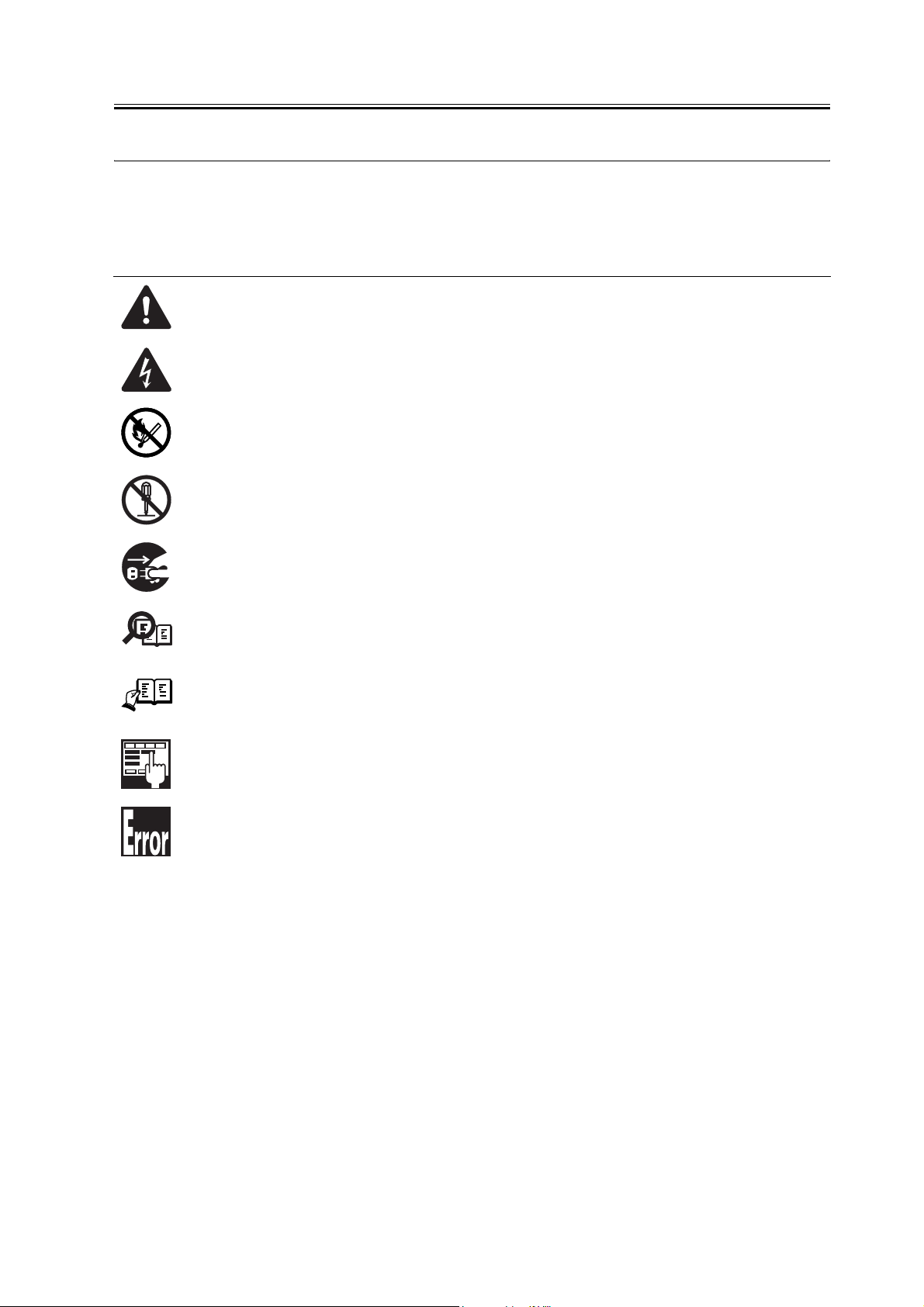
Symbols Used
This documentation uses the following symbols to indicate special information:
Symbol Description
Indicates an item of a non-specific nature, possibly classified as Note, Caution, or Warning.
Indicates an item requiring care to avoid electric shocks.
Indicates an item requiring care to avoid combustion (fire).
Indicates an item prohibiting disassembly to avoid electric shocks or problems.
Introduction
Memo
REF.
Indicates an item requiring disconnection of the power plug from the electric outlet.
Indicates an item intended to provide notes assisting the understanding of the topic in question.
Indicates an item of reference assisting the understanding of the topic in question.
Provides a description of a service mode.
Provides a description of the nature of an error indication.
Page 5

Introduction
The following rules apply throughout this Service Manual:
1. Each chapter contains sections explaining the purpose of specific functions and the relationship between electrical and mechanical systems with reference to the timing of operation.
In the diagrams, represents the path of mechanical drive; where a signal name accom-
panies the symbol , the arrow indicates the direction of the electric signal.
The expression "turn on the power" means flipping on the power switch, closing the front
door, and closing the delivery unit door, which results in supplying the machine with power.
2. In the digital circuits, '1'is used to indicate that the voltage level of a given signal
is "High", while '0' is used to indicate "Low".(The voltage value, however, differs from
circuit to circuit.) In addition, the asterisk (*) as in "DRMD*" indicates that the DRMD
signal goes on when '0'.
In practically all cases, the internal mechanisms of a microprocessor cannot be checked in
the field. Therefore, the operations of the microprocessors used in the machines are not
discussed: they are explained in terms of from sensors to the input of the DC controller PCB
and from the output of the DC controller PCB to the loads.
The descriptions in this Service Manual are subject to change without notice for product improvement or other purposes, and major changes will be communicated in the form of Service
Information bulletins.
All service persons are expected to have a good understanding of the contents of this Service
Manual and all relevant Service Information bulletins and be able to identify and isolate
faults in the machine."
Page 6

Page 7

Contents
Contents
Chapter 1 Installation Procedure
1.1 Unpacking and Checking the Components.................................................................................................... 2
1.1.1Unpacking and Checking components...................................................................................................... 2
1.2 Installation Procedure ........................................................................................................................................ 4
1.2.1Turning Off the Host Machine..................................................................................................................... 4
1.2.2Installation Procedure .................................................................................................................................. 4
1.3 Checking the Operation ..................................................................................................................................... 8
1.3.1Setting of type ............................................................................................................................................... 8
1.3.2Setting of line type ........................................................................................................................................ 8
1.3.3Fax communication test............................................................................................................................... 8
Page 8

Contents
Page 9

Chapter 1 Installation
Procedure
Page 10

Chapter 1
1.1 Unpacking and Checking the Components
1.1.1 Unpacking and Checking components
[1] [2]
[4] [5] [6] [7] [8]
0011-1971
[3]
[9]
[10] [11] [12] [13] [14] [15] [16] [17]
F-1-1
[1] Fax unit 1 pc
[2] Speaker unit 1 pc
[3] Speaker relay cable 1 pc
[4] Telephone cord
It is included only with the products destined for North America.
[5] Telephone cord
It is included only with the products destined for Australia.
[6] Telephone cord
It is included only with the products destined for Europe.
It is used in Germany only.
1 pc
1 pc
1 pc
2
Page 11

Chapter 1
[7] Telephone cord
1 pc
It is included only with the products destined for Europe.
It is used in France only.
[8] Telephone cord
1 pc
It is included only with the products destined for Europe.
It is used in UK only.
[9] Screw (RS tight; M4X10) 4 pc
[10] Screw (Bind; M4X8) 2 pc
[11] TP screw (M3X6) 2 pc
[12] Modular label 1 pc
[13] FCC lavel
1 pc
It is included only with the products destined for North America.
[14] A-TICK label
1 pc
It is included only with the products destined for Australia.
[15] FAX Approval label
1 pc
It is included only with the products destined for Europe.
It is used in Germany only.
[16] Fax Driver CD-ROM unit 1 pc
[17] Sending and Facsimile Guide 1 pc
3
Page 12

Chapter 1
1.2 Installation Procedure
1.2.1 Turning Off the Host
Machine
Turning Off the Main Power
When turning off the main power, be sure to go
through the following in strict sequence to protect the
machine's hard disk:
[1] Hold down on the power switch on the control
panel for 3 sec or more.
[2] Operate on the touch panel according to the shut-
down sequence indicated so that the main power
switch may be turned off.
[3] Turn off the main power switch.
[4] Disconnect the power cable (for the power outlet).
0011-4316
[2]
[1]
[2]
F-1-3
3) Detach the upper right cover [1].
- 2 screws [2]
[2]
[1]
1.2.2 Installation Proce-
dure
1) Release a cable from four clamps [1] and discon-
nect the connector [2].
[2]
[1]
F-1-2
2) Detach the rear cover [1].
- 7 screws [2]
0011-1976
F-1-4
4) Detach the upper right rear cover [1].
- A connector [2]
- 2 screws [3]
[3]
[2]
[1]
[3]
F-1-5
4
Page 13

5) Affix a modular label to the upper right rear cover
[1].
[2] Only Japan
[3] Only Europe
[4] Others than those above
[1]
EXT.
[2]
HAND
SET
LINE 1
LINE 2
Chapter 1
[1]
LINE 1
[3]
LINE 1
LINE 2
[4]
F-1-6
6) Cut out the blanking area [1] with nippers and the
like.
F-1-7
7) Detach the support plate [1] of rear cover.
- 2 screws [2]
[2]
[1]
F-1-8
Those screws and the support plate are not used fur-
ther.
8) Detach the controller box cover [1].
5
Page 14

Chapter 1
- 16 screws [2]
[1]
[2]
[2]
[2]
[2]
F-1-9
9) Detach the Fax unit cover [1].
- 3 screws [2]
[2]
[1]
[2]
[1]
[2]
F-1-11
11) Run the cable [2] through the wire clip [1] and in-
sert two connectors [3].
[2]
[1]
[3]
F-1-12
F-1-10
10) Mount the Fax unit [1].
- 4 screws (RS tight; M4X10) [2]
6
12) Insert the connector [2] of the cable [1] and fix the
cable with four clamps [3].
[2]
[3]
[1]
F-1-13
13) Mount the speaker unit [1].
Page 15

- 2 screws (Bind; M4X8) [2]
Chapter 1
Be sure not get caught the speaker cable in the gap.
Mount the unit from below so that it does not hit the
control panel.
[1]
[2]
F-1-14
14) Connect the connector [2] of the speaker relay ca-
ble [1], run it through 13 clamps [3] and three wire
clips [4], and insert it into the connector [5].
[4]
[1]
[3] [3]
[4]
[4]
[3]
[2]
[1]
F-1-16
17) Mount the covers detached.
- The upper right rear cover
- The upper right cover
- The rear cover
18) Adjust a supplied label to the specified line [1] of
the rear cover (lower) and offix it to the correct po-
sition.
[2] A-TICK label
[3] FCC label
[4] FAX Approval label
[3]
[2]
[4]
[2]
[3]
[3]
F-1-15
15) Mount the controller box cover.
16) Mount the Fax unit cover [1].
- 3 screws [2] unscrewed at step 9)
- 2 screws [3] (TP; M3X6)
[3]
[5]
[1]
F-1-17
19) Insert one end of the telephone cord into the mod-
ular jack on the wall, and insert the other end into
'LINE 1' of the modular jack on the main body.
20) Plug the power code of the main body into the out-
let and turn on the main power switch.
7
Page 16

Chapter 1
1.3 Checking the Operation
1.3.1 Setting of type
In service mode, select the type of the fax board as follows: press the Additional Function key, press the 2 and 8 keys
at the same time, and press the Additional Function key once again; then, select [fax] and then [type], and select the
country and the region using the Up/Down key. At the end, press the OK key.
1.3.2 Setting of line type
Set the line to a dial line or a push line according to the phone line type to be connected. The setting procedure is as
follows.
Additional Functions > Communications Settings > User Settings in Fax Settings > Tel Line Type
1.3.3 Fax communication test
Perform a communication test to check if the function of facsimile works correctly.
1) Bring up the Send screen on the control panel.
2) Send a test original to a party capable of a communication test, and check to see if the original is sent normally.
3) Send a text original from the other party, and check to see if the original is sent normally.
0011-2056
0011-2057
0011-2058
8
Page 17

Jan 25 2006
Page 18

 Loading...