

Page 1

Service Manual
Finisher, Sorter, DeliveryTray
Puncher Unit-N1
Oct 19 2006
Page 2

Page 3

Application
This manual has been issued by Canon Inc. for qualified persons to learn technical theory, installation, maintenance, and repair
of products. This manual covers all localities where the products are sold. For this reason, there may be information in this
manual that does not apply to your locality.
Corrections
This manual may contain technical inaccuracies or typographical errors due to improvements or changes in products. When
changes occur in applicable products or in the contents of this manual, Canon will release technical information as the need
arises. In the event of major changes in the contents of this manual over a long or short period, Canon will issue a new edition
of this manual.
The following paragraph does not apply to any countries where such provisions are inconsistent with local law.
Trademarks
The product names and company names used in this manual are the registered trademarks of the individual companies.
Copyright
This manual is copyrighted with all rights reserved. Under the copyright laws, this manual may not be copied, reproduced or
translated into another language, in whole or in part, without the written consent of Canon Inc.
COPYRIGHT © 2001 CANON INC.
Printed in Japan
Caution
Use of this manual should be strictly supervised to avoid disclosure of confidential information.
Page 4
Symbols Used
This documentation uses the following symbols to indicate special information:
Symbol Description
Indicates an item of a non-specific nature, possibly classified as Note, Caution, or Warning.
Indicates an item requiring care to avoid electric shocks.
Indicates an item requiring care to avoid combustion (fire).
Indicates an item prohibiting disassembly to avoid electric shocks or problems.
Indicates an item requiring disconnection of the power plug from the electric outlet.
Indicates an item intended to provide notes assisting the understanding of the topic in question.
Memo
Introduction
REF.
Indicates an item of reference assisting the understanding of the topic in question.
Provides a description of a service mode.
Provides a description of the nature of an error indication.
Page 5

Introduction
The following rules apply throughout this Service Manual:
1. Each chapter contains sections explaining the purpose of specific functions and the relationship between electrical and mechanical systems with reference to the timing of operation.
In the diagrams, represents the path of mechanical drive; where a signal name accompanies the symbol , the arrow indicates the
direction of the electric signal.
The expression "turn on the power" means flipping on the power switch, closing the front door, and closing the delivery unit door, which results in
supplying the machine with power.
2. In the digital circuits, '1'is used to indicate that the voltage level of a given signal is "High", while '0' is used to indicate "Low".(The voltage value, however, differs from circuit to circuit.) In addition, the asterisk (*) as in "DRMD*" indicates that the DRMD signal goes on when '0'.
In practically all cases, the internal mechanisms of a microprocessor cannot be checked in the field. Therefore, the operations of the microprocessors
used in the machines are not discussed: they are explained in terms of from sensors to the input of the DC controller PCB and from the output of the
DC controller PCB to the loads.
The descriptions in this Service Manual are subject to change without notice for product improvement or other purposes, and major changes will be communicated in the form of Service Information bulletins.
All service persons are expected to have a good understanding of the contents of this Service Manual and all relevant Service Information bulletins and be
able to identify and isolate faults in the machine."
Page 6

Page 7

Contents
Contents
Chapter 1 Specifications
1.1 Product Specifications ................................................................................................................................1- 1
1.1.1 Specifications ..........................................................................................................................................................1- 1
1.2 Names of Parts ...........................................................................................................................................1- 2
1.2.1 External View...........................................................................................................................................................1- 2
1.2.2 Cross Section ..........................................................................................................................................................1- 3
Chapter 2 Functions
2.1 Basic Construction......................................................................................................................................2- 1
2.1.1 Functional Construction...........................................................................................................................................2- 1
2.2 Feed Drive System .....................................................................................................................................2- 1
2.2.1 Overview..................................................................................................................................................................2- 1
2.2.2 Constraction of the Control System.........................................................................................................................2- 1
2.2.3 Punch Operation......................................................................................................................................................2- 2
2.2.4 Horizontal Registration Operation ...........................................................................................................................2- 4
2.3 Detecting Jams ...........................................................................................................................................2- 6
2.3.1 Detecting Jams........................................................................................................................................................2- 6
2.4 Power Supply ............................................................................................................................................. 2- 6
2.4.1 Power Supply Route ...............................................................................................................................................2- 6
2.4.2 Protection Function..................................................................................................................................................2- 6
Chapter 3 Parts Replacement Procedure
3.1 External Covers ..........................................................................................................................................3- 1
3.1.1 Rear Cover ..............................................................................................................................................................3- 1
3.1.1.1 Removing the Rear Cover ....................................................................................................................................................... 3- 1
3.1.2 Upper Cover ............................................................................................................................................................3- 1
3.1.2.1 Removing the Rear Cover ....................................................................................................................................................... 3- 1
3.1.2.2 Removing the Upper Cover ..................................................................................................................................................... 3- 1
3.1.3 Right Guide Unit ......................................................................................................................................................3- 1
3.1.3.1 Removing the Right Guide Unit ............................................................................................................................................... 3- 1
3.2 Drive System .............................................................................................................................................. 3- 1
3.2.1 Punch Motor ............................................................................................................................................................3- 1
3.2.1.1 Removing the Rear Cover ....................................................................................................................................................... 3- 1
3.2.1.2 Removing the Upper Cover ..................................................................................................................................................... 3- 2
3.2.1.3 Removing the Punch Motor ..................................................................................................................................................... 3- 2
3.2.2 Horizontal Registration Motor ..................................................................................................................................3- 2
3.2.2.1 Removing the Rear Cover ....................................................................................................................................................... 3- 2
3.2.2.2 Removing the Right Guide Unit ............................................................................................................................................... 3- 2
3.2.2.3 Removing the Horizontal Registration Motor ........................................................................................................................... 3- 2
3.2.3 Punch Unit ...............................................................................................................................................................3- 2
3.2.3.1 Notification when dismounting the Punch Unit......................................................................................................................... 3- 2
3.2.3.2 Removing the Rear Cover ....................................................................................................................................................... 3- 2
3.2.3.3 Removing the Right Guide Unit ............................................................................................................................................... 3- 2
3.2.3.4 Removing the Upper Cover ..................................................................................................................................................... 3- 3
3.2.3.5 Removing the Punch Unit ........................................................................................................................................................ 3- 3
3.3 Electrical System ........................................................................................................................................3- 4
3.3.1 Punch Unit Harness.................................................................................................................................................3- 4
3.3.1.1 Notification when dismounting the Punch Unit Harness ......................................................................................................... 3- 4
3.3.1.2 Removing the Rear Cover ....................................................................................................................................................... 3- 4
3.3.1.3 Removing the Right Guide Unit ............................................................................................................................................... 3- 4
Page 8

Contents
3.3.1.4 Removing the Upper Cover ..................................................................................................................................................... 3- 5
3.3.1.5 Removing the Punch Unit Harness .......................................................................................................................................... 3- 5
3.3.1.6 Installing the Punch Unit Harness ............................................................................................................................................ 3- 6
3.3.2 LED PCB..................................................................................................................................................................3- 6
3.3.2.1 Removing the Rear Cover ....................................................................................................................................................... 3- 6
3.3.2.2 Removing the Right Guide Unit ............................................................................................................................................... 3- 6
3.3.2.3 Removing the Upper Cover ..................................................................................................................................................... 3- 6
3.3.2.4 Removing the Punch Unit ........................................................................................................................................................ 3- 7
3.3.2.5 Removing the LED PCB .......................................................................................................................................................... 3- 8
3.3.3 Photosensor PCB ....................................................................................................................................................3- 8
3.3.3.1 Removing the Rear Cover ....................................................................................................................................................... 3- 8
3.3.3.2 Removing the Upper Cover ..................................................................................................................................................... 3- 8
3.3.3.3 Removing the Photosensor PCB ............................................................................................................................................. 3- 8
3.3.4 Scrap Full Detector PCB..........................................................................................................................................3- 8
3.3.4.1 Removing the Right Guide Unit ............................................................................................................................................... 3- 8
3.3.4.2 Removing the Scrap Full Detector PCB................................................................................................................................... 3- 9
3.3.5 Punch Controller PCB..............................................................................................................................................3- 9
3.3.5.1 Removing the Rear Cover ....................................................................................................................................................... 3- 9
3.3.5.2 Removing the Punch Controller PCB....................................................................................................................................... 3- 9
Chapter 4 Maintenance
4.1 User Maintenance ...................................................................................................................................... 4- 1
4.1.1 User Maintenance....................................................................................................................................................4- 1
4.2 Maintenance and Inspection ...................................................................................................................... 4- 1
4.2.1 Periodically Replaced Parts.....................................................................................................................................4- 1
4.2.1.1 Periodically Replaced Parts ..................................................................................................................................................... 4- 1
4.2.2 Durables...................................................................................................................................................................4- 1
4.2.2.1 Durables................................................................................................................................................................................... 4- 1
4.2.3 Periodical Servicing .................................................................................................................................................4- 1
4.2.3.1 Periodical Servicing ................................................................................................................................................................ 4- 1
4.3 Adjustment ................................................................................................................................................. 4- 1
4.3.1 Adjustment at Time of Parts Replacement ..............................................................................................................4- 1
4.3.1.1 Adjusting the Punch Hole Position (feed direction) .................................................................................................................. 4- 1
4.3.1.2 Sensor Output Adjustment ....................................................................................................................................................... 4- 1
4.3.1.3 Registering the Number of Punch Holes.................................................................................................................................. 4- 1
4.4 Troubleshooting.......................................................................................................................................... 4- 1
4.4.1 Error Code ...............................................................................................................................................................4- 1
4.4.1.1 E503; Puncher unit communication error................................................................................................................................. 4- 1
4.4.1.2 E505; Backup RAM error ......................................................................................................................................................... 4- 1
4.4.1.3 E590; Punch motor error.......................................................................................................................................................... 4- 1
4.4.1.4 E591; Scrap full detector sensor error ..................................................................................................................................... 4- 2
4.4.1.5 E592; Trailing edge/Horizontal registration sensor error ......................................................................................................... 4- 2
4.4.1.6 E593; Horizontal registration motor error ................................................................................................................................. 4- 2
4.5 Outline of Electrical Components ............................................................................................................... 4- 2
4.5.1 Sensors....................................................................................................................................................................4- 2
4.5.2 Microswitches ..........................................................................................................................................................4- 3
4.5.3 Motors......................................................................................................................................................................4- 4
4.5.4 PCBs........................................................................................................................................................................4- 5
4.6 Variable Resistors (VR), Light-Emitting Diodes (LED), and Check Pins by PCB ....................................... 4- 5
4.6.1 Overview..................................................................................................................................................................4- 5
4.6.2 Punch Controller PCB..............................................................................................................................................4- 6
4.7 Upgrading................................................................................................................................................... 4- 6
4.7.1 Upgrading ................................................................................................................................................................4- 6
4.8 Service Tools............................................................................................................................................ 4- 11
4.8.1 Solvents and Oils ...................................................................................................................................................4- 11
Chapter 5 Error Code
Page 9

Contents
5.1 Overview..................................................................................................................................................... 5- 1
5.1.1 Overview..................................................................................................................................................................5- 1
5.2 User Error Code .........................................................................................................................................5- 1
5.2.1 Punch scrap full .......................................................................................................................................................5- 1
5.2.2 Punch scrap overflow ..............................................................................................................................................5- 1
5.3 Service Error Code .....................................................................................................................................5- 1
5.3.1 E503 ........................................................................................................................................................................5- 1
5.3.2 E505 ........................................................................................................................................................................5- 1
5.3.3 E590 ........................................................................................................................................................................5- 1
5.3.4 E591 ........................................................................................................................................................................5- 1
5.3.5 E592 ........................................................................................................................................................................5- 2
5.3.6 E593 ........................................................................................................................................................................5- 2
Page 10

Contents
Page 11

Chapter 1 Specifications
Page 12

Page 13

Contents
Contents
1.1 Product Specifications....................................................................................................................................................1-1
1.1.1 Specifications ............................................................................................................................................................................... 1-1
1.2 Names of Parts ...............................................................................................................................................................1-2
1.2.1 External View .............................................................................................................................................................................. 1-2
1.2.2 Cross Section ............................................................................................................................................................................... 1-3
Page 14

Page 15

1.1 Product Specifications
Chapter 1
1.1.1 Specifications
Å@
Hole position
T-1-1
Item Specifications Remarks
Punching method Reciprocating punching (Sequential punching)
Paper size 2 holes (Puncher Unit-L1):
A3, A4, A4R, B4, B5, B5R
2 or 3 holes (Puncher Unit-M1):
2 holes/LGL, LTRR
3 holes/279mm x 432mm (11 x 17), LTR
4 holes (FRA)(Puncher Unit-N1):
A3, A4
4 holes (SWD)(Puncher Unit-P1):
A3, A4
Paper weight 64g/m2 to 256g/m2 TransparenCies not
Punched hole
diameter
Punched scrap
capacity
Dimensions 107 x 615 x 378mm (W x D x H)
Weight Approx. 7.2 kg
Power supply From finisher unit (24 VDC / 5 VDC)
2 holes : 6.5mm
2 or 3 holes : 8mm
4 holes : 6.5mm
2 holes: 10,000 sheets or more 80 g/m2 paper
2 or 3 holes: 3,000 sheets or more
4 holes: 5,000 sheets or more
allowed
0003-4694
1-1
Page 16
Chapter 1
[1] Puncher unit-L1 (2-Hole)
40±3 mm
80±1 mm / 3.15±0.04 in
[2] Puncher unit-M1 (2-/3-Hole)
35±3 mm
70±1 mm / 2.76±0.04 in
108±3 mm
108±1 mm /
4.25±0.04 in
108±1 mm /
4.25±0.04 in
12±3 mm /
0.47±0.12 in
12±3 mm /
0.47±0.12 in
12±3 mm /
0.47±0.12 in
1.2 Names of Parts
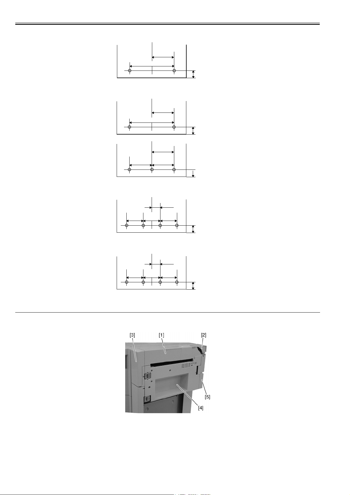
1.2.1 External View
[3] Puncher unit-N1 (4-Hole (FRA))
40±3 mm
80±1 mm /
80±1 mm /
3.15±0.04 in
80±1 mm /
3.15±0.04 in
3.15±0.04 in
[4] Puncher unit-P1 (4-Hole (SWD))
35±3 mm
21±1 mm /
70±1 mm /
2.76±0.04 in
21±1 mm /
0.83±0.04 in
F-1-1
0.83±0.04 in
12±3 mm /
0.47±0.12 in
12±3 mm /
0.47±0.12 in
0003-4695
1-2
F-1-2
T-1-2
[1] Upper cover
[2] Upper cover 2
Page 17
[3] Front door
[4] Right guide assembly
[5] Rear cover
Chapter 1
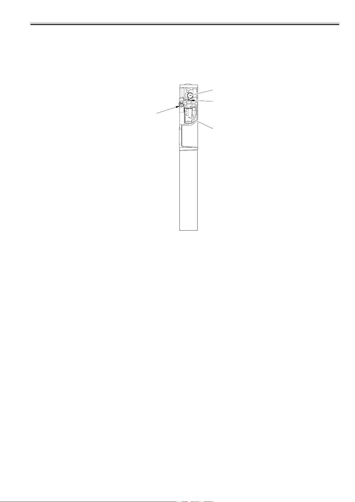
1.2.2 Cross Section
0003-4696
[1]
[2]
[3]
[4]
F-1-3
T-1-3
[1] Cam [3] Punch feed roller
[2] Hole puncher (Punch blade) [4] Punch waste case
1-3
Page 18

Page 19

Chapter 2 Functions
Page 20

Page 21

Contents
Contents
2.1 Basic Construction .........................................................................................................................................................2-1
2.1.1 Functional Construction ............................................................................................................................................................... 2-1
2.2 Feed Drive System .........................................................................................................................................................2-1
2.2.1 Overview...................................................................................................................................................................................... 2-1
2.2.2 Constraction of the Control System ............................................................................................................................................. 2-1
2.2.3 Punch Operation........................................................................................................................................................................... 2-2
2.2.4 Horizontal Registration Operation ............................................................................................................................................... 2-4
2.3 Detecting Jams ...............................................................................................................................................................2-6
2.3.1 Detecting Jams ............................................................................................................................................................................. 2-6
2.4 Power Supply .................................................................................................................................................................2-6
2.4.1 Power Supply Route ................................................................................................................................................................... 2-6
2.4.2 Protection Function ...................................................................................................................................................................... 2-6
Page 22

Page 23

2.1 Basic Construction
Chapter 2
2.1.1 Functional Construction
The puncher unit is optionally installed in the delivery path between the host machine and the finisher.
When the paper delivered from the host machine reaches the puncher unit, it is fed by the punch feed roller. Then when the trailing edge of the paper is detected,
the paper is tempo-rarily stopped and the punch axis rotates to punch holes in the trailing edge of the paper. These operations are controlled by the finisher controller
0003-8735
PCB and the punch controller PCB drives each puncher component.
Punch
drive
Feed
system
drive
system
Horizontal
registration
drive
system
Finisher unit
control system
F-2-1
Punch
controller
PCB
2.2 Feed Drive System
2.2.1 Overview
The puncher unit is located on the feed path between the host machine and the finisher, and successively punches holes when the paper stops temporarily.
The paper delivered from the host machine is fed by the punch feed roller. The punch feed roller is driven by the punch feed motor. When the trailing edge of the
paper reaches the puncher unit, the inlet roller of the finisher unit temporarily stops the paper and holes are punched on the trailing edge of the paper.
The following shows the names and functions of the motors and sensors used in punching operation:
Motor Function
Punch motor (M61) Drives the punch unit.
Horizontal registration motor (M62) Drives the punch slide unit.
Punch feed motor(M63) Drives the punch feed roller.
Sensor Function
Horizontal registration home position sensor
(PI61)
Punch motor clock sensor (PI62) Detects the punch motor clock.
Punch home position sensor (PI63) Detects the punch shaft home position.
Horizontal registration sensor (LED1 to
LED4,PTR1 to PTR4)
Trailing edge sensor (LED5,PTR5) Detects the trailing edge of paper.
Scrap full detector sensor (LED6,PTR6) Detects the state of the punch waste case (full).
T-2-1
T-2-2
Detects the punch slide unit home position.
Detects the position of the rear edge of paper.
2.2.2 Constraction of the Control System
The puncher unit consists of a die and hole puncher (punch blade).
The hole puncher is driven by the punch motor (M61). The hole puncher is attached to the
eccentric cam of the punch shaft, and rotary action of the punch shaft is converted to reciprocal motion to perform punching.
Punch motor (M61) is a DC motor. The home position of the punch shaft is detected by punch home position sensor (PI63). To stop the DC punch motor accurately
at its home po-sition, the punch motor clock sensor (PI62) counts a predetermined number of clock pulses to stop the punch motor. A single punch operation is
performed by rotating the punch shaft 180° from its home position.
Five light sensors (photosensor PCB) are located at the upper side of the inlet paper feed path of the puncher unit and a set of five LEDs (LED PCB) are located at
the lower side. These sensors and LEDs function as five sensors. The frontmost sensor (LED5, PTR5) are the trailing edge sensor and are used for detecting the
trailing edge of the paper. The remaining sensors (LED1 to LED4, PTR1 to PTR4) are horizontal registration sensors, and are used for detecting the inner position
of the paper for determining the hole punching position.
The punch motor, puncher unit and above sensors comprise the punch slide unit. This unit moves backwards and forwards according to the size of the paper. Backward and forward movement is driven by the horizontal registration motor (M62). The home position of the punch slide unit is detected by the horizontal registration
home position sensor (PI61). The horizontal registration motor (M62) is a 2-phase stepping motor.
The punch motor and horizontal registration motor is driven by the punch controller PCB
according to control signals from the finisher controller PCB.
Punch scraps caused by punching are stored in the punched scrap container. Scrap full detection is performed by a reflective sensor (LED6 and PTR6 on the scrap
full detector PCB unit).
0003-9479
0003-4698
2-1
Page 24

Chapter 2
Punch controller PCB (1/2)
PAEND
Trailing edge detection signal
Horizontal registration detection signal
(LED1 to 4, PTR1 to 4) SREG1 to 4
5
5
Punch motor clock (PI62)
Punch motor (M61) drive signal
detection signal PUNCHCLK
PTR1
2
3
4
LED1
2
3
4
PUNCHHP
Punch home position (PI63)
detection signal
SREGHP
(LED6,PTR6) DFULL
Scrap full detection signal
Horizontal registration home position (PI61) detection signal
Punch feed motor (M63) drive signal
Horizontal registration motor (M62) drive signal
Punch controller PCB (2/2)
F-2-2
2.2.3 Punch Operation
The hole puncher is driven by the punch motor (M61), and its position is monitored by the punch home position sensor (PI63).
The hole puncher makes a single round-trip movement (punching) as the punch shaft rotates 180°Å@from home position.
In the case of a 2-or-3 hole type, the half sector of the punch shaft is used when punching 2 holes while the half sector on the opposite side is used when punching
0003-4699
3 holes as instructed by the host machine.
<2-/4-hole Type>
At the home position, the punch home position sensor is ON. Punching of the first sheet ends when the punch shaft has rotated in the forward direction 180°, and
the state of the punch home position sensor has changed from OFF to ON. Punching of the second sheet ends when the punch shaft has rotated in the reverse direction
180° , and the state of the punch home position sensor has changed from OFF to ON.
The following illustrates punching when two sheets are punched.
1) A hole is punched in the trailing edge of the first sheet.
2-2
Page 25

Punch home
position sensor
(PI63)
Chapter 2
Sensor flag
Punch shaft
Eccentric
cam
Die
Die
[punch shaft stopped/
home position]
Hole
puncher
Sheet
Punched scrap
[punch shaft rotated 90˚
in the forward direction /
hole punched]
F-2-3
[punch shaft rotated 180˚
in the forward direction /
punch operation completed]
2) A hole is punched in the trailing edge of the second sheet.
[punch shaft stopped/
home position]
<2-/3-hole Dual Use Type>
At the home position, the punch home position sensor is ON. To punch two holes, punching of the first sheet ends when the punch shaft half peripheral area has
rotated in the forward direction 180°, and the state of the punch home position sensor has changed from OFF to ON. At this time, the 3-hole puncher is moved
reciprocally in the escape direction (hole puncher rise direction) on the remaining half peripheral area on the punch shaft. Punching of the second sheet ends when
the punch shaft half peripheral area has rotated in the reverse direction 180°, and the state of the punch home position sensor has changed from OFF to ON. Also
at this time, the 3-hole puncher is moved reciprocally in the escape direction (hole puncher rise direction) on the remaining half peripheral area on the punch shaft.
To punch three holes, the 2-hole puncher is moved reciprocally in the escape direction (hole puncher rise direction).
The following illustrates punching when two sheets are punched with two holes.
[punch shaft rotated 90˚
in the reverse direction/
hole punched]
F-2-4
[punch shaft rotated 180˚
in the reverse direction/
punch operation completed]
1) A hole is punched in the trailing edge of the first sheet.
Punch home
position
sensor (PI63)
Eccentric
cam
Sensor flag
Punch shaft
Hole
puncher
Die
Die
[punch shaft stopped/
home position]
Sheet
[punch shaft is rotated 90˚
in the forward direction/
hole punched]
Punched scrap
[punch shaft is rotated 180˚
in the forward direction/
punch operation completed]
F-2-5
When two holes are punched, the 3-hole puncher is fed reciprocally in the escape direction (hole puncher rise direction) as shown below.
2-3
Page 26

Chapter 2
[punch shaft stopped/
home position]
[punch shaft is rotated 90˚
in the forward direction/
hole puncher rises to
topmost position]
F-2-6
[punch shaft is rotated 180˚
in the forward direction/
hole puncher returns to
original position]
2) A hole is punched in the trailing edge of the second sheet.
[punch shaft stopped/
home position]
[punch shaft is rotated 90˚
in the reverse direction/
hole punched]
F-2-7
[punch shaft is rotated 180˚
in the reverse direction/
punch operation completed]
When two holes are punched, the 3-hole puncher is fed reciprocally in the escape direction (hole puncher rise direction) as shown below.
[punch shaft stopped/
home position]
2.2.4 Horizontal Registration Operation
Horizontal registration drive of the punch slide unit is performed by the horizontal registration motor (M62). The home position of the punch slide unit is detected
by the horizontal registration home position sensor (PI61). The punch slide unit detects the trailing edge of the paper by the trailing edge sensor (LED5, PTR5) and
horizontal registration sensors (LED1 to 4, SREG1 to 4) and is moved to the trailing edge position matched to the paper size.
[punch shaft is rotated 90˚
in the reverse direction/
hole puncher rises to
topmost position]
F-2-8
[punch shaft is rotated 180˚
in the reverse direction/
hole puncher returns to
original position]
0003-4700
The following shows horizontal registration operation.
1) When the leading edge of the paper from the host machine is detected by the trailing edge sensor (LED5, PTR5) on the puncher unit, the horizontal registration
motor (M62) starts to move the punch slide unit towards the front.
2-4
Page 27

Chapter 2
Punch slide unit
Horizontal registration motor (M62)
Trailing edge detection sensor
(LED5,PTR5)
Sheet delivery direction
Sheet
F-2-9
2) After the horizontal registration sensors (LED1 to 4, PTR1 to 4) detect the edge of the paper at its inner side in keeping with the paper size signals arriving from
the host ma-chine, the horizontal registration motor (M62) drives the punch slide unit to a predetermined position further towards the front, and stops the unit at
this position.
Horizontal registration sensor 1(LED1,PTR1)
: detects the edge of A3, A4, LTR, and 279 mm x 432 mm (11'' x 17'') papers
Horizontal registration sensor 2 (LED2,PTR2)
: detects the edge of B4, B5, LTR-R, and LGL papers
Horizontal registration sensor 3 (LED3,PTR3)
: detects the edge of A4R paper
Horizontal registration sensor 4 (LED4,PTR4)
: detects the edge of B5R paper
F-2-10
3) When the trailing edge sensor (LED5, PTR5) detects the trailing edge of the paper, drive of the punch feed motor (M63) is stopped to stop paper feed. Next, the
punch motor (M161) is driven to punch holes in the paper.
Punch
F-2-11
4) When punching ends, drive of the punch feed motor (M63) is started, the horizontal registration motor (M62) is operated in the reverse direction, and the punch
slide unit is returned to its home position where it comes to a stop.
5) Even if paper to be punched continues to arrive, the punch slide unit returns to its home position for each arriving sheet, and steps 1 to 4 are repeated.
2-5
Page 28

Chapter 2
2.3 Detecting Jams
Trailing edge detection
sensor (LED5, PTR5)
Horizontal registration sensor
(LED1 to 4, PTR1 to 4)
Punch home position
sensor (PI63)
Horizontal registration home
position sensor (PI61)
Horizontal registration
motor (M62)
Punch motor (M61)
First feed motor (M63)
: Motor CW : Motor CCW
F-2-12
2.3.1 Detecting Jams
The finisher unit identifies any of the following conditions as a jam, and sends the jam signal to the host machine. In response, the host machine may stop copying
0003-4704
operation and indicate the presence of a jam on its control panel.
T-2-3
Jam type Sensor Jam Condition Code
Feeding
delay
Feeding
stationary
Punch PI63 When the punch home position sensor (PI63 ) does not turn
LED5,PTR5When the rear end sensor (LED, PTR5) does not detect
LED5,PTR5When paper does not exit the rear end sensor (LED,
paper after a prescribed time (distance) has elapsed since
receiving a delivery signal from the host machine.
PTR5) after feeding for a prescribed time (distance) after
the rear end sensor (LED, PTR5) has detected paper.
on after a prescribe time has elapsed since it is turned off.
Power-on LED5,PTR5When paper is detected by the rear end sensor (LED,
iR C3100/
3170/2570
1002 1012
1102 1122
1644 1644
1645 1645
iR4570/
3570, 2570/
2270
PTR5) during power on.
2.4 Power Supply
2.4.1 Power Supply Route
24V power and 5V power are supplied from the finisher controller PCB when the power switch on the host machine is turned ON.
24V power is used for driving motors, while 5V power is used for driving sensors and the ICs on the punch controller PCB.
24V power to the motors is not supplied when either of the two door switches on the puncher unit is open.
Upper door
switch
(MSW61)
Front door
switch
(MSW62)
0003-4702
24V
Punch controller PCB
Finisher
controller
PCB
5V
F-2-13
2.4.2 Protection Function
The 24V power supplies are equipped with a fuse designed to blow when an overcurrent flows.
2-6
24V
24V
5V
5V
5V
Motor system
Motor system
LED PCB
Sensors
Logic
0003-4703
Page 29

Chapter 3 Parts Replacement Procedure
Page 30

Page 31

Contents
Contents
3.1 External Covers..............................................................................................................................................................3-1
3.1.1 Rear Cover ................................................................................................................................................................................... 3-1
3.1.1.1 Removing the Rear Cover ...............................................................................................................................................................................3-1
3.1.2 Upper Cover................................................................................................................................................................................. 3-1
3.1.2.1 Removing the Rear Cover ...............................................................................................................................................................................3-1
3.1.2.2 Removing the Upper Cover ............................................................................................................................................................................3-1
3.1.3 Right Guide Unit.......................................................................................................................................................................... 3-1
3.1.3.1 Removing the Right Guide Unit .....................................................................................................................................................................3-1
3.2 Drive System..................................................................................................................................................................3-1
3.2.1 Punch Motor................................................................................................................................................................................. 3-1
3.2.1.1 Removing the Rear Cover ...............................................................................................................................................................................3-1
3.2.1.2 Removing the Upper Cover ............................................................................................................................................................................3-2
3.2.1.3 Removing the Punch Motor ............................................................................................................................................................................3-2
3.2.2 Horizontal Registration Motor ..................................................................................................................................................... 3-2
3.2.2.1 Removing the Rear Cover ...............................................................................................................................................................................3-2
3.2.2.2 Removing the Right Guide Unit .....................................................................................................................................................................3-2
3.2.2.3 Removing the Horizontal Registration Motor.................................................................................................................................................3-2
3.2.3 Punch Unit ................................................................................................................................................................................... 3-2
3.2.3.1 Notification when dismounting the Punch Unit ..............................................................................................................................................3-2
3.2.3.2 Removing the Rear Cover ...............................................................................................................................................................................3-2
3.2.3.3 Removing the Right Guide Unit .....................................................................................................................................................................3-2
3.2.3.4 Removing the Upper Cover ............................................................................................................................................................................3-3
3.2.3.5 Removing the Punch Unit ...............................................................................................................................................................................3-3
3.3 Electrical System............................................................................................................................................................3-4
3.3.1 Punch Unit Harness...................................................................................................................................................................... 3-4
3.3.1.1 Notification when dismounting the Punch Unit Harness ...............................................................................................................................3-4
3.3.1.2 Removing the Rear Cover ...............................................................................................................................................................................3-4
3.3.1.3 Removing the Right Guide Unit .....................................................................................................................................................................3-4
3.3.1.4 Removing the Upper Cover ............................................................................................................................................................................3-5
3.3.1.5 Removing the Punch Unit Harness .................................................................................................................................................................3-5
3.3.1.6 Installing the Punch Unit Harness...................................................................................................................................................................3-6
3.3.2 LED PCB ..................................................................................................................................................................................... 3-6
3.3.2.1 Removing the Rear Cover ...............................................................................................................................................................................3-6
3.3.2.2 Removing the Right Guide Unit .....................................................................................................................................................................3-6
3.3.2.3 Removing the Upper Cover ............................................................................................................................................................................3-6
3.3.2.4 Removing the Punch Unit ...............................................................................................................................................................................3-7
3.3.2.5 Removing the LED PCB .................................................................................................................................................................................3-8
3.3.3 Photosensor PCB ......................................................................................................................................................................... 3-8
3.3.3.1 Removing the Rear Cover ...............................................................................................................................................................................3-8
3.3.3.2 Removing the Upper Cover ............................................................................................................................................................................3-8
3.3.3.3 Removing the Photosensor PCB .....................................................................................................................................................................3-8
3.3.4 Scrap Full Detector PCB.............................................................................................................................................................. 3-8
3.3.4.1 Removing the Right Guide Unit .....................................................................................................................................................................3-8
3.3.4.2 Removing the Scrap Full Detector PCB .........................................................................................................................................................3-9
3.3.5 Punch Controller PCB.................................................................................................................................................................. 3-9
3.3.5.1 Removing the Rear Cover ...............................................................................................................................................................................3-9
3.3.5.2 Removing the Punch Controller PCB .............................................................................................................................................................3-9
Page 32

Page 33

3.1 External Covers
3.1.1 Rear Cover
Chapter 3
3.1.1.1 Removing the Rear Cover
1) Remove three screws [1] and remove the rear cover [2].
F-3-1
3.1.2 Upper Cover
3.1.2.1 Removing the Rear Cover
1) Remove three screws [1] and remove the rear cover [2].
0003-6789
0003-6790
F-3-3
3.1.3 Right Guide Unit
3.1.3.1 Removing the Right Guide Unit
1) Remove four screws [1], and remove the right guide assembly [2].
0003-6792
F-3-2
3.1.2.2 Removing the Upper Cover
1) Open the front door [1], remove three screws [2], and remove the upper
cover [3].
0003-6791
F-3-4
3.2 Drive System
3.2.1 Punch Motor
3.2.1.1 Removing the Rear Cover
1) Remove three screws [1] and remove the rear cover [2].
F-3-5
0003-6793
3-1
Page 34

Chapter 3
3.2.1.2 Removing the Upper Cover
1) Open the front door [1], remove three screws [2], and remove the upper
0003-6794
cover [3].
F-3-6
3.2.1.3 Removing the Punch Motor
1) Disconnect the connector [1].
2) Remove two screws [2] and remove the punch motor [3].
0003-6795
F-3-9
3.2.2.3 Removing the Horizontal Registration Motor
1) Disconnect the connector [1].
2) Remove two screws [2] and slide the horizontal registration motor [3] in
the direction of the arrow to remove.
0003-6798
F-3-7
3.2.2 Horizontal Registration Motor
3.2.2.1 Removing the Rear Cover
1) Remove three screws [1] and remove the rear cover [2].
0003-6796
F-3-10
3.2.3 Punch Unit
3.2.3.1 Notification when dismounting the Punch Unit
When removing the punch unit, the punch unit section sometimes opens.
If necessary, perform work with the punch unit section in an open state.
3.2.3.2 Removing the Rear Cover
1) Remove three screws [1] and remove the rear cover [2].
0003-8233
0003-6800
F-3-8
3.2.2.2 Removing the Right Guide Unit
1) Remove four screws [1], and remove the right guide assembly [2].
3-2
0003-6797
F-3-11
3.2.3.3 Removing the Right Guide Unit
1) Remove four screws [1], and remove the right guide assembly [2].
0003-6799
Page 35

F-3-12
Chapter 3
section [2] to the front side.
3.2.3.4 Removing the Upper Cover
1) Open the front door [1], remove three screws [2], and remove the upper
0003-6801
cover [3].
F-3-13
3.2.3.5 Removing the Punch Unit
1) Remove E-ring [1], washer [2], and puncher spring [3].
0003-6802
F-3-15
3) Remove the three screws [1], and remove the sensor mount (upper) [2].
Then, remove the connector [3] on the photosensor PCB.
F-3-16
4) Disconnect the connector [1] and remove the screw [2], and remove the
horizontal registration home position sensor [3].
[3]
F-3-14
2) Turn the gear [1] in the direction of the arrow, and move the punch unit
[1]
[2]
F-3-17
5) Turn the gear [1] in the direction of the arrow, and move the punch unit
section [2] to the far side.
3-3
Page 36

Chapter 3
F-3-18
6) Remove the tie wrap with lock [1] while holding its claw between your
fingers. (The tie wrap must be removed without being cut.)
7) Disconnect the three connectors [2] and remove the screw [3], and remove
the harness guide [4].
[2]
The slide shaft support [1] is not attached to punch unit section that are
currently set as service parts. When replacing the punch unit section, be
sure to attach the slide shaft support that was in use beforehand. If you
forget to attach the slide shaft support, the machine may malfunction.
[1]
[3]
[2]
F-3-22
3.3 Electrical System
3.3.1 Punch Unit Harness
3.3.1.1 Notification when dismounting the Punch Unit Harness
When removing the punch unit, the punch unit section sometimes opens.
If necessary, perform work with the punch unit section in an open state.
0003-8728
[2]
[3]
[1]
[4]
F-3-19
8) Lift up the front side of the punch unit section [1] first, then move in the
direction of the arrow to remove the punch unit section [1].
F-3-20
9) Disconnect the connector [1] on LED PCB.
3.3.1.2 Removing the Rear Cover
1) Remove three screws [1] and remove the rear cover [2].
F-3-23
3.3.1.3 Removing the Right Guide Unit
1) Remove four screws [1], and remove the right guide assembly [2].
0003-6804
0003-6805
[1]
F-3-21
10) Remove the slide shaft support [1], the sensor mount (lower) [2] and the
puncher knob [3] from the punch unit section.
3-4
F-3-24
Page 37

Chapter 3
3.3.1.4 Removing the Upper Cover
1) Open the front door [1], remove three screws [2], and remove the upper
0003-6803
cover [3].
F-3-25
3.3.1.5 Removing the Punch Unit Harness
1) Disconnect the two connectors [2] on the punch controller PCB [1] and
remove the harness from the edge saddle [3].
0003-6807
F-3-28
6) Remove the three screws [1] and sensor mount (upper) [2].
7) Disconnect the connector [3] on the photosensor PCB and the connector
[4] on the LED PCB and remove the harness from the edge saddle [5].
F-3-26
2) Remove the two tie wraps with lock [1] while holding its claw between
your fingers. (The tie wraps must be removed without being cut.)
3) Disconnect the three connectors [2].
4) Free the harness [4] from the three harness stops [3].
[2]
[2]
[3]
[1]
[3]
[1]
[4]
[3]
F-3-27
5) Turn the gear [1] in the direction of the arrow, and move the punch unit
section [2] to the front side.
F-3-29
8) Free the harness [2] from the four harness stops [1].
F-3-30
3-5
Page 38

Chapter 3
9) Disconnect the connector [1] of the horizontal registration motor and the
connector [2] of the horizontal registration home position sensor, and remove the punch unit harness.
F-3-31
3.3.1.6 Installing the Punch Unit Harness
0003-6806
Offset punch unit harnesses can cause malfunction. The punch unit
harnesses must be firmly installed at the positions described below.
1) Fasten the punch unit harnesses so that the two tie wraps [1] of the punch
unit harnesses are on the outside of the two respective clamps [2].
3.3.2 LED PCB
3.3.2.1 Removing the Rear Cover
1) Remove three screws [1] and remove the rear cover [2].
F-3-34
3.3.2.2 Removing the Right Guide Unit
1) Remove four screws [1], and remove the right guide assembly [2].
0003-6809
0004-0830
PI62
PI63
M61
LED PCB
Potosensor
PCB
PI61
M62
F-3-32
F-3-33
[1]
[1]
Punch Controller
PCB
F-3-35
3.3.2.3 Removing the Upper Cover
1) Open the front door [1], remove three screws [2], and remove the upper
cover [3].
F-3-36
0003-6810
3-6
Page 39

Chapter 3
3.3.2.4 Removing the Punch Unit
1) Remove E-ring [1], washer [2], and puncher spring [3].
F-3-37
2) Turn the gear [1] in the direction of the arrow, and move the punch unit
section [2] to the front side.
0004-0831
horizontal registration home position sensor [3].
[3]
[1]
[2]
F-3-40
5) Turn the gear [1] in the direction of the arrow, and move the punch unit
section [2] to the far side.
F-3-38
3) Remove the three screws [1], and remove the sensor mount (upper) [2].
Then, remove the connector [3] on the photosensor PCB.
F-3-41
6) Remove the tie wrap with lock [1] while holding its claw between your
fingers. (The tie wrap must be removed without being cut.)
7) Disconnect the three connectors [2] and remove the screw [3], and remove
the harness guide [4].
[2]
[2]
[3]
[1]
[4]
F-3-42
8) Lift up the front side of the punch unit section [1] first, then move in the
direction of the arrow to remove the punch unit section [1].
F-3-39
4) Disconnect the connector [1] and remove the screw [2], and remove the
3-7
Page 40

Chapter 3
F-3-43
9) Disconnect the connector [1] on LED PCB.
F-3-47
[1]
F-3-44
10) Remove the slide shaft support [1], the sensor mount (lower) [2] and the
puncher knob [3] from the punch unit section.
The slide shaft support [1] is not attached to punch unit section that are
currently set as service parts. When replacing the punch unit section, be
sure to attach the slide shaft support that was in use beforehand. If you
forget to attach the slide shaft support, the machine may malfunction.
[1]
[3]
[2]
F-3-45
3.3.2.5 Removing the LED PCB
1) Remove the screw [1], and remove the LED PCB [2].
0004-0827
3.3.3.2 Removing the Upper Cover
1) Open the front door [1], remove three screws [2], and remove the upper
0003-6812
cover [3].
F-3-48
3.3.3.3 Removing the Photosensor PCB
1) Remove the screw [1].
0004-0829
2) Disconnect the connector [2] and the remove the Photosensor PCB [3].
F-3-46
3.3.3 Photosensor PCB
3.3.3.1 Removing the Rear Cover
1) Remove three screws [1] and remove the rear cover [2].
3-8
0003-6813
F-3-49
3.3.4 Scrap Full Detector PCB
3.3.4.1 Removing the Right Guide Unit
1) Remove four screws [1], and remove the right guide assembly [2].
0003-6817
Page 41

F-3-50
Chapter 3
3.3.4.2 Removing the Scrap Full Detector PCB
1) Remove the screw [1], disconnect the connector [2], and remove the scrap
0003-6818
full detector PCB unit [3].
F-3-51
3.3.5 Punch Controller PCB
3.3.5.1 Removing the Rear Cover
1) Remove three screws [1] and remove the rear cover [2].
0003-6819
F-3-53
F-3-52
3.3.5.2 Removing the Punch Controller PCB
1) Remove the two screws [1], disconnect seven connectors [2], and remove
the punch controller PCB [3].
0003-6820
3-9
Page 42

Page 43

Chapter 4 Maintenance
Page 44

Page 45

Contents
Contents
4.1 User Maintenance ..........................................................................................................................................................4-1
4.1.1 User Maintenance ........................................................................................................................................................................ 4-1
4.2 Maintenance and Inspection...........................................................................................................................................4-1
4.2.1 Periodically Replaced Parts ......................................................................................................................................................... 4-1
4.2.1.1 Periodically Replaced Parts.............................................................................................................................................................................4-1
4.2.2 Durables ....................................................................................................................................................................................... 4-1
4.2.2.1 Durables ..........................................................................................................................................................................................................4-1
4.2.3 Periodical Servicing ..................................................................................................................................................................... 4-1
4.2.3.1 Periodical Servicing .......................................................................................................................................................................................4-1
4.3 Adjustment.....................................................................................................................................................................4-1
4.3.1 Adjustment at Time of Parts Replacement .................................................................................................................................. 4-1
4.3.1.1 Adjusting the Punch Hole Position (feed direction) .......................................................................................................................................4-1
4.3.1.2 Sensor Output Adjustment ..............................................................................................................................................................................4-1
4.3.1.3 Registering the Number of Punch Holes.........................................................................................................................................................4-1
4.4 Troubleshooting .............................................................................................................................................................4-1
4.4.1 Error Code.................................................................................................................................................................................... 4-1
4.4.1.1 E503; Puncher unit communication error ....................................................................................................................................................... 4-1
4.4.1.2 E505; Backup RAM error ............................................................................................................................................................................... 4-1
4.4.1.3 E590; Punch motor error.................................................................................................................................................................................4-1
4.4.1.4 E591; Scrap full detector sensor error.............................................................................................................................................................4-2
4.4.1.5 E592; Trailing edge/Horizontal registration sensor error ...............................................................................................................................4-2
4.4.1.6 E593; Horizontal registration motor error....................................................................................................................................................... 4-2
4.5 Outline of Electrical Components..................................................................................................................................4-2
4.5.1 Sensors ......................................................................................................................................................................................... 4-2
4.5.2 Microswitches .............................................................................................................................................................................. 4-3
4.5.3 Motors .......................................................................................................................................................................................... 4-4
4.5.4 PCBs ............................................................................................................................................................................................ 4-5
4.6 Variable Resistors (VR), Light-Emitting Diodes (LED), and Check Pins by PCB.......................................................4-5
4.6.1 Overview...................................................................................................................................................................................... 4-5
4.6.2 Punch Controller PCB.................................................................................................................................................................. 4-6
4.7 Upgrading.......................................................................................................................................................................4-6
4.7.1 Upgrading .................................................................................................................................................................................... 4-6
4.8 Service Tools................................................................................................................................................................4-11
4.8.1 Solvents and Oils ....................................................................................................................................................................... 4-11
Page 46

Page 47

4.1 User Maintenance
Chapter 4
4.1.1 User Maintenance
T-4-1
No. Item Timing
1 Punch waste removal When prompted (indicator on host machine control
0003-4705
4.2 Maintenance and Inspection
4.2.1 Periodically Replaced Parts
4.2.1.1 Periodically Replaced Parts
The Puncher unit does not have parts that must be replaced on a periodical
basis.
Item Interval Description Remark
Transmittance sensor 25 million sheets Cleaning Wipe with dry cloth
0003-4706
4.3 Adjustment
4.3.1 Adjustment at Time of Parts Replacement
4.3.1.1 Adjusting the Punch Hole Position (feed direction)
This adjustment is possible only with the host machine service mode.
4.3.1.2 Sensor Output Adjustment
Perform this adjustment when replacing the punch controller PCB, transmittance sensor (photosensor PCB/LED PCB), or deflection sensor (scrap full
detector PCB unit).
1) Check that the power of the host machine is off and then remove the rear
cover of the puncher.
2) Set SW601 on the punch controller PCB as shown below.
ON
1234
F-4-1
3) Turn on the power of the host machine.
4) Press SW602 on the punch controller PCB. Sensor output is adjusted au-
tomatically when the switch is pressed.
Adjustment is complete if LED601 and 602 on the punch controller PCB
flashes alternately.
5) Press SW602 or 603 on the punch controller PCB to end the adjustment
mode and set all bits of SW601 to OFF.
6) Turn off the power of the host machine.
4.3.1.3 Registering the Number of Punch Holes
This operation registers which puncher unit is attached to the IC on the punch
driver PCB so that the puncher unit can be identified by the finisher. For this
reason, this operation must be performed when the punch driver PCB has
been replaced.
1) Check that the power of the host machine is off and then remove the rear
cover of the puncher.
2) Set SW601 on the punch controller PCB as shown below.
ON
1234
F-4-2
3) Turn on the power of the host machine.
4) Press SW602 on the punch controller PCB to select the number of punch
holes.
The items in the following table are displayed repeatedly from top to bottom
each time SW602 is pressed.
Number of
punch holes
2 hole(Puncher
Unit-L1)
T-4-3
LED601/602
Flash 1 times per cycle
0003-4709
0003-4710
0003-4711
panel)
4.2.2 Durables
4.2.2.1 Durables
There are no durables that require durables.
4.2.3 Periodical Servicing
4.2.3.1 Periodical Servicing
T-4-2
Number of
punch holes
2/3
hole(Puncher
Unit-M1)
4 hole(Puncher
Unit-N1(FRA))
4 hole(Puncher
Unit-P1(SWD))
LED601/602
Flash 2 times per cycle
Flash 3 times per cycle
Flash 4 times per cycle
5) Press SW603 on the punch controller PCB. The number of punch holes is
registered to the punch controller PCB each time the switch is pressed.
Registration is complete if LED601 and 602 on the punch controller PCB
flashes alternately.
6) Press SW602 or 603 on the punch controller PCB to end the adjustment
mode and set all bits of SW601 to OFF.
7) Turn off the power of the host machine.
4.4 Troubleshooting
4.4.1 Error Code
4.4.1.1 E503; Puncher unit communication error
<Finisher controller PCB/Punch controller PCB>
1) Does it improve when the host machine power switch is turned OFF/ON?
YES : End
<Wiring>
2) Is the wiring between the finisher controller PCB and punch controller
PCB normal?
NO : Repair the wiring.
<Finisher controller PCB/Punch controller PCB>
3) Does it improve when the finisher controller PCB and punch controller
PCB are replaced?
YES : End
4.4.1.2 E505; Backup RAM error
<Punch controller PCB>
1) Does it improve when the host machine power switch is turned OFF/ON?
YES : End
No : Replace the punch controller PCB.
4.4.1.3 E590; Punch motor error
<Punch home position sensor (PI63)>
1) Check the punch home position sensor. Does the sensor operate normally?
NO : Replace the sensor.
<Punch motor clock sensor (PI62)>
2) Check the punch motor clock sensor. Does the sensor operate normally?
NO : Replace the sensor.
<Wiring>
3) Is the wiring between the punch controller PCB and sensors normal?
NO : Repair the wiring.
<Punch mechanism/Punch motor (M61)>
4) Is there any abnormality in the punch mechanism?
YES : Repair the punch mechanism.
NO : Replace the punch motor.
<Punch controller PCB/Finisher controller PCB>
5) Does it improve when the punch controller PCB is replaced?
0003-4707
0003-4708
0003-4712
0003-4713
0003-4714
4-1
Page 48

Chapter 4
YES : End
NO : Replace the finisher controller PCB.
4.4.1.4 E591; Scrap full detector sensor error
<Wiring>
1) Is the wiring between the scrap full detector PCB and the punch controller
PCB normal?
NO : Repair the wiring.
<Scrap full detector PCB>
2) Does it improve when the scrap full detector PCB is replaced?
YES : End
NO : Replace the punch controller PCB.
<Punch controller PCB/Finisher controller PCB>
3) Does it improve when the punch controller PCB is replaced?
YES : End
NO : Replace the finisher controller PCB.
0003-8758
4.4.1.5 E592; Trailing edge/Horizontal registration sensor error
<Wiring>
1) Is the wiring between the LED PCB/photosensor PCB and the punch con-
troller PCB normal?
NO : Repair the wiring.
<LED PCB/Photosensor PCB>
2) Does it improve when the LED PCB/photosensor PCB is replaced?
YES : End
NO : Replace the punch controller PCB.
<Punch controller PCB/Finisher controller PCB>
3) Does it improve when the punch controller PCB is replaced?
YES : End
NO : Replace the finisher controller PCB.
4.4.1.6 E593; Horizontal registration motor error
<Horizontal registration home position sensor (PI61)>
1) Check the horizontal registration home position sensor. Does the sensor
operate normally?
NO : Replace the sensor.
<Wiring>
2) Is the wiring between the punch controller PCB and the sensor normal?
NO : Repair the wiring.
<Horizontal registration mechanism/ Horizontal registration motor (M62)>
3) Is there any abnormality in the horizontal registration mechanism?
YES : Repair the horizontal registration mechanism.
NO : Replace the horizontal registration motor.
<Punch controller PCB/Finisher controller PCB>
4) Does it improve when the punch controller PCB is replaced?
YES : End
NO : Replace the finisher controller PCB.
Ref. Name
PI61 Horizontal registration home position sensor WG8-5593 J605 E593
PI62 Punch motor clock sensor FK2-0149 J605 E590
PI63 Punch home position sensor FK2-0149 J605 1644 E590
0003-8760
0003-4715
4.5 Outline of Electrical Components
4.5.1 Sensors
PI62
PI61
F-4-3
T-4-4
Parts
number
Punch
controlle
r PCB
JAM Error
0005-8426
PI63
4-2
Page 49

Chapter 4
4.5.2 Microswitches
MSW62
MSW61
0005-8427
T-4-5
F-4-4
Ref. Name Parts number Punch controller PCB
MSW61 Upper door switch WC4-5128 J602
MSW62 Front door switch WC4-5128 J602
4-3
Page 50

Chapter 4
4.5.3 Motors
M61
M62
M63
0005-8428
T-4-6
F-4-5
Ref. Name Parts number Punch controller PCB Error
M61 Punch motor FH5-1074 J603 E590
M62 Horizontal registration motor FH5-1075 J605 E593
M63 Punch feed motor FH5-1043 J604
4-4
Page 51

Chapter 4
4.5.4 PCBs
0005-8429
[2]
[3]
[1]
[4]
F-4-6
T-4-7
Ref. Name Parts number
[1] Punch controller PCB FG3-2885 E505
[2] Photosensor PCB FG3-3108 J605
[3] LED PCB FG3-3107 J605 E592
[4] Scrap full detector PCB FM2-1521 J606 E591
Punch
controller
PCB
JAM Error
1002,1102
,1645
E592
4.6 Variable Resistors (VR), Light-Emitting Diodes (LED), and Check Pins by PCB
4.6.1 Overview
Of the LEDs and check pins used in the machine, those needed during servicing in the field are discussed.
Do not touch the check pins not found in the list herein. They are exclusively for factory use, and require special tools and a high degree of accuracy.
0003-4721
4-5
Page 52

Chapter 4
4.6.2 Punch Controller PCB
Switch Function
SW601 Used to set various adjustment mode settings.
SW602 Used to make adjustments, start input, and store the input.
SW603 Used to store input.
J603
J605
J606
2
1
A13
A1
4
1
16
J602
17
J608
SW601
F-4-7
T-4-8
41
J604
J601
J607
A1
A11
SW602
SW603
0003-4722
1
3
4.7 Upgrading
4.7.1 Upgrading
Overview
A flash ROM is used for the IC601 (CPU) of the Puncher unit. To upgrade this IC, the downloader PCB (FY9-2034) is used. The operating instructions for it are
given below.
How to Use the Downloader PCB (FY9-2034)
1.When to Use the Downloader PCB
The downloader PCB is used when upgrading the CPU (IC601) of the Punch Controller PCB.
2.Member part of the downloader PCB
[1] [2] [3] [4] [6][7][5] [8]
F-4-8
T-4-9
No. Description Function
[1] START/STOP key A key to be pressed when you start or stop download
[2] LOAD LED To be lit when download is available.
[3] Model LED To be lit when the Puncher is connected.
[4] Power LED To be lit when power is supplied from the Puncher to the downloader
[5] RS-232C cable (straight full
wiring; 9 pins)
[6] Cable A (9 pins) Length:
approx. 70cm
PCB
A cable to connect the downloader PCB and a PC.Be sure to connect the
cable in a way that its ferrite core comes to the PC side.
A cable to connect the downloader PCB and other products
0003-8729
4-6
Page 53

No. Description Function
[7] Cable B (9 pins)Length:
approx. 50cm
[8] RS-232C connector A connector to connect an RS-232C cable to the downloader PCB
A cable to connect the downloader PCB and the Puncher
3. Necessary Tool
The following item needs to be prepared for download.
Computer (PC)
Prerequisite: The download tool (Ver. 1.73E or higher) must be downloaded to the PC.
4. Download Procedures
a. Addition of ROM data
1) Store ROM data to be downloaded in the 'C:\ServTool\NewROM' folder.
2) Start up the Service Support Tool.
C:\ProgramFiles\Service Support Tool\bpchost.exe
3) Select [Controlling Data].
Chapter 4
F-4-9
4) Select [Registering Firmware].
F-4-10
5) Select [Register from New ROM folder].
In response, the data will be registered, and the data inside the NewROM folder will be deleted.
4-7
Page 54

Chapter 4
F-4-11
b. Connection to the Puncher
1) Turn off the power of the host machine.
2) Remove the rear cover of the Puncher.
3) Insert the cable B to J608 on the Punch controller PCB.
4) Connect the RS-232C cable to the RS-232C connectors of the circuit board and the PC.
5) Turn on the power of the host machine.
The power LED on the circuit board is lit.
c. Download
The error code E500 might occur during download. It does not affect the download operation and its results.
1) Start up the Service Support Tool.
C:\ProgramFiles\Service Support Tool\bpchost.exe
2) Select [Downloading/Uploading].
3) Press the START/STOP key.
LOAD LED is lit.
4) Select the Puncher.
When the model name you selected is highlighted, press the Connect key.
4-8
F-4-12
Page 55

5) Follow the instructions on the screen to prepare for downloading.
A press on [OK] will bring up the next screen.
Chapter 4
F-4-13
6) Select the version of the ROM to download.
F-4-14
4-9
Page 56

Chapter 4
F-4-15
7) Press [Start] so that the computer and the downloaded PCB will start downloading the program.
8) If downloading ended normally, press [OK].
4-10
F-4-16
Page 57

9) End the session as instructed on the screen.
Chapter 4
F-4-17
5. Release of Connection
1) Press the START/STOP key.
LOAD LED is turned off.
2) Turn off the power of the host machine.
3) Disconnect the cable B from the Puncher.
4) Mount the rear cover to the Puncher.
5) Turn on the power of the host machine.
4.8 Service Tools
4.8.1 Solvents and Oils
No. Name Description Composition Remarks
1 Vic Clean Cleaning:
2 Lubricant Sliding units Silicone oil MOLYKOTE EM30-L
e.g., glass,
plastic, rubber parts,
external covers
F-4-18
T-4-10
Hydrocarbon(fluorine
family)
Alcohol
Surface activating agent
Water
Do not bring near fire.
Procure locally.
Isopropyl alcohol may be
substituted.
0003-4723
4-11
Page 58

Page 59

Chapter 5 Error Code
Page 60

Page 61

Contents
Contents
5.1 Overview........................................................................................................................................................................5-1
5.1.1 Overview...................................................................................................................................................................................... 5-1
5.2 User Error Code .............................................................................................................................................................5-1
5.2.1 Punch scrap full............................................................................................................................................................................ 5-1
5.2.2 Punch scrap overflow................................................................................................................................................................... 5-1
5.3 Service Error Code.........................................................................................................................................................5-1
5.3.1 E503 ............................................................................................................................................................................................. 5-1
5.3.2 E505 ............................................................................................................................................................................................. 5-1
5.3.3 E590 ............................................................................................................................................................................................. 5-1
5.3.4 E591 ............................................................................................................................................................................................. 5-1
5.3.5 E592 ............................................................................................................................................................................................. 5-2
5.3.6 E593 ............................................................................................................................................................................................. 5-2
Page 62

Page 63

5.1 Overview
Chapter 5
5.1.1 Overview
The finisher to which the unit is mounted is equipped with a mechanism (CPU on the finisher controller PCB) that runs a self check, communicating to the host
machine any fault it detects in the form of a code and a detail code.
In response, the host machine indicates the presence of a fault on its control panel using codes; the detail codes may be checked in the host machine's service mode.
0003-4736
5.2 User Error Code
5.2.1 Punch scrap full
Error
Description
Punch scrap
full
5.2.2 Punch scrap overflow
Error
Description
Punch scrap
overflow
T-5-1
Occurs when Detection timing Machine operation Reset
The amount of punch
scraps has reached the
scrap container
capacity.
During punching Normal operation will
continue.
Empty the scrap
container.
T-5-2
Occurs when Detection timing Machine operation Reset
The amount of punch
scraps has exceeded
the scrap container
During punching Punching will be
disabled.
Empty the scrap
container.
capacity.
0003-4737
0003-4738
5.3 Service Error Code
5.3.1 E503
T-5-3
Code Detail Error Description Detection timing
E503 0003 Communication error The communication with the puncher unit is interrupted.
0003-4739
5.3.2 E505
5.3.3 E590
5.3.4 E591
T-5-4
Code Detail Error Description Detection timing
E505 0002 Backup RAM The checksum for the punch controller PCB has an error
when the power is turned on.
T-5-5
Code Detail Error Description Detection timing
E590 8001 Punch motor (M61)/
Punch motor clock
8002 After the motor has been stopped at time of punch motor
sensor (PI62)/
Punch home position
sensor (PI63)
The puncher does not detect the punch home position sensor
when the puncher motor has been driven for 20 msec.
initialization, the puncher does not detect punch home
position sensor.
T-5-6
Code Detail Error Description Detection timing
E591 8001 Scrap full detector
sensor (LED6,PTR6)
The voltage of the light received is 3.0 V or less even when
the light emitting duty of the scrap full detector sensor has
been increased to 66% or more.
8002 The voltage of the light received is 2.0 V or more even when
the light emitting duty of the scrap full detector sensor has
been decreased to 0%.
0003-4740
0003-4741
0003-8764
5-1
Page 64

Chapter 5
5.3.5 E592
T-5-7
Code Detail Error Description Detection timing
E592 8001 Trailing edge
8002 The voltage of the light received is 2.0 V or more even when
sensor(LED5,PTR5)/
Horizontal registration
sensor (LED1 to 4,PTR1
to 4)
The voltage of the light received is 2.5 V or less even when
the light emitting duty of the trailing edge sensor has been
increased to 66% or more.
the light emitting duty of the trailing edge sensor has been
decreased to 0%.
8003 The voltage of the light received is 2.5 V or less even when
the light emitting duty of the horizontal registration sensor 1
(LED1,PTR1) has been increased to 66% or more.
8004 The voltage of the light received is 2.0 V or more even when
the light emitting duty of the horizontal registration sensor 1
(LED1,PTR1) has been decreased to 0%.
8005 The voltage of the light received is 2.5 V or less even when
the light emitting duty of the horizontal registration sensor 2
(LED2,PTR2) has been increased to 66% or more.
8006 The voltage of the light received is 2.0 V or more even when
the light emitting duty of the horizontal registration sensor 2
(LED2,PTR2) has been decreased to 0%.
8007 The voltage of the light received is 2.5 V or less even when
the light emitting duty of the horizontal registration sensor 3
(LED3,PTR3) has been increased to 66% or more.
8008 The voltage of the light received is 2.0 V or more even when
the light emitting duty of the horizontal registration sensor 3
(LED3,PTR3) has been decreased to 0%.
8009 The voltage of the light received is 2.5 V or less even when
the light emitting duty of the horizontal registration sensor 4
(LED4,PTR4) has been increased to 66% or more.
800A The voltage of the light received is 2.0 V or more even when
the light emitting duty of the horizontal registration sensor 4
(LED4,PTR4) has been decreased to 0%.
0003-8767
5.3.6 E593
T-5-8
Code Detail Error Description Detection timing
E593 8001 Horizontal registration
motor(M62)/
Horizontal registration
8002 At time of horizontal registration motor initialization, the
home position sensor
(PI61)
At time of horizontal registration motor initialization, the
punch slide unit does not leave the horizontal home position
sensor even when it has been driven for 9 mm.
punch slide unit does not return to the horizontal registration
home position sensor even when the unit has been driven for
37 mm.
0003-4742
5-2
Page 65

Oct 19 2006
Page 66

 Loading...