

Page 1

Portable Manual
Finisher, Sorter, DeliveryTray
Puncher Unit-N1
Oct 19 2006
Page 2

Page 3

Application
This manual has been issued by Canon Inc. for qualified persons to learn technical theory, installation, maintenance, and repair
of products. This manual covers all localities where the products are sold. For this reason, there may be information in this
manual that does not apply to your locality.
Corrections
This manual may contain technical inaccuracies or typographical errors due to improvements or changes in products. When
changes occur in applicable products or in the contents of this manual, Canon will release technical information as the need
arises. In the event of major changes in the contents of this manual over a long or short period, Canon will issue a new edition
of this manual.
The following paragraph does not apply to any countries where such provisions are inconsistent with local law.
Trademarks
The product names and company names used in this manual are the registered trademarks of the individual companies.
Copyright
This manual is copyrighted with all rights reserved. Under the copyright laws, this manual may not be copied, reproduced or
translated into another language, in whole or in part, without the written consent of Canon Inc.
COPYRIGHT © 2001 CANON INC.
Printed in Japan
Caution
Use of this manual should be strictly supervised to avoid disclosure of confidential information.
Page 4
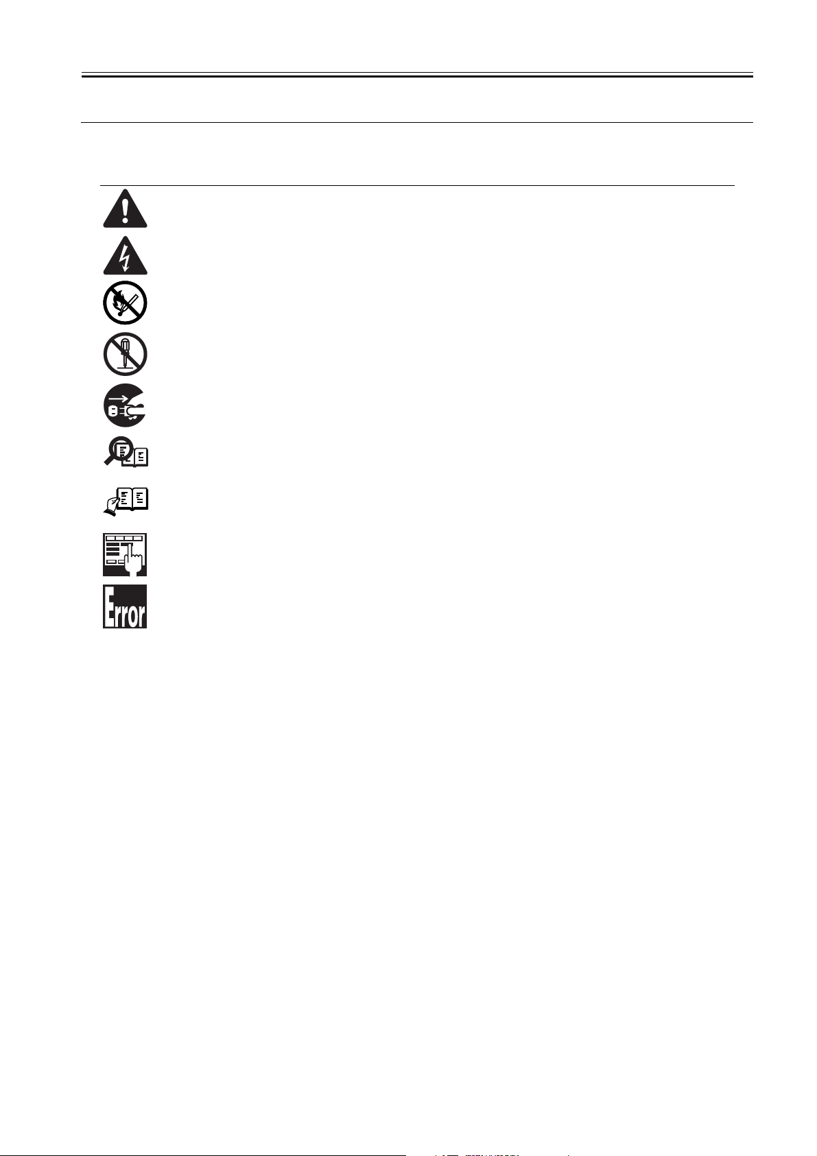
Symbols Used
This documentation uses the following symbols to indicate special information:
Symbol Description
Indicates an item of a non-specific nature, possibly classified as Note, Caution, or Warning.
Indicates an item requiring care to avoid electric shocks.
Indicates an item requiring care to avoid combustion (fire).
Indicates an item prohibiting disassembly to avoid electric shocks or problems.
Indicates an item requiring disconnection of the power plug from the electric outlet.
Indicates an item intended to provide notes assisting the understanding of the topic in question.
Memo
Introduction
REF.
Indicates an item of reference assisting the understanding of the topic in question.
Provides a description of a service mode.
Provides a description of the nature of an error indication.
Page 5

Introduction
The following rules apply throughout this Service Manual:
1. Each chapter contains sections explaining the purpose of specific functions and the relationship between electrical and mechanical systems with reference to the timing of operation.
In the diagrams, represents the path of mechanical drive; where a signal name accompanies the symbol , the arrow indicates the
direction of the electric signal.
The expression "turn on the power" means flipping on the power switch, closing the front door, and closing the delivery unit door, which results in
supplying the machine with power.
2. In the digital circuits, '1'is used to indicate that the voltage level of a given signal is "High", while '0' is used to indicate "Low".(The voltage value, however, differs from circuit to circuit.) In addition, the asterisk (*) as in "DRMD*" indicates that the DRMD signal goes on when '0'.
In practically all cases, the internal mechanisms of a microprocessor cannot be checked in the field. Therefore, the operations of the microprocessors
used in the machines are not discussed: they are explained in terms of from sensors to the input of the DC controller PCB and from the output of the
DC controller PCB to the loads.
The descriptions in this Service Manual are subject to change without notice for product improvement or other purposes, and major changes will be communicated in the form of Service Information bulletins.
All service persons are expected to have a good understanding of the contents of this Service Manual and all relevant Service Information bulletins and be
able to identify and isolate faults in the machine."
Page 6

Page 7

Contents
Contents
Chapter 1 Maintenance and Inspection
1.1 Periodically Replaced Parts ...............................................................................................................................1
1.1.1Periodically Replaced Parts .........................................................................................................................1
1.2 Durables ................................................................................................................................................................1
1.2.1Durables ..........................................................................................................................................................1
1.3 Periodical Servicing.............................................................................................................................................1
1.3.1Periodical Servicing ......................................................................................................................................1
Chapter 2 Standards and Adjustments
2.1 Adjustment at Time of Parts Replacement......................................................................................................3
2.1.1Adjusting the Punch Hole Position (feed direction) ..................................................................................3
2.1.2Sensor Output Adjustment ...........................................................................................................................3
2.1.3Registering the Number of Punch Holes....................................................................................................3
Chapter 3 Error Code
3.1 Overview ...............................................................................................................................................................5
3.1.1Overview .........................................................................................................................................................5
3.2 User Error Code ...................................................................................................................................................5
3.2.1Punch scrap full..............................................................................................................................................5
3.2.2Punch scrap overflow....................................................................................................................................5
3.3 Service Error Code..............................................................................................................................................5
3.3.1E503.................................................................................................................................................................5
3.3.2E505.................................................................................................................................................................5
3.3.3E590.................................................................................................................................................................5
3.3.4E591.................................................................................................................................................................5
3.3.5E592.................................................................................................................................................................6
3.3.6E593.................................................................................................................................................................6
Chapter 4 Outline of Components
4.1 Outline of Electrical Components......................................................................................................................7
4.1.1Sensors ...........................................................................................................................................................7
4.1.2Microswitches .................................................................................................................................................8
4.1.3Motors..............................................................................................................................................................9
4.1.4PCBs..............................................................................................................................................................10
4.2 Variable Resistors (VR), Light-Emitting Diodes (LED), and Check Pins by PCB....................................10
4.2.1Overview .......................................................................................................................................................10
4.2.2Punch Controller PCB.................................................................................................................................11
Chapter 5 System Construction
Page 8

Contents
5.1 Basic Construction............................................................................................................................................ 13
5.1.1Functional Construction .............................................................................................................................13
5.2 Product Specifications...................................................................................................................................... 13
5.2.1Specifications............................................................................................................................................... 13
Chapter 6 Upgrading
6.1 Upgrading.......................................................................................................................................................... 15
Page 9

Chapter 1 Maintenance and Inspection
1.1 Periodically Replaced Parts
Chapter 1
1.1.1 Periodically Replaced Parts
The Puncher unit does not have parts that must be replaced on a periodical basis.
1.2 Durables
1.2.1 Durables
There are no durables that require durables.
1.3 Periodical Servicing
1.3.1 Periodical Servicing
Item Interval Description Remark
Transmittance sensor 25 million sheets Cleaning Wipe with dry cloth
0003-4706
0003-4707
0003-4708
T-1-1
1
Page 10

Page 11

Chapter 2 Standards and
Adjustments
2.1 Adjustment at Time of Parts Replacement
Chapter 2
2.1.1 Adjusting the Punch Hole Position (feed direction)
This adjustment is possible only with the host machine service mode.
2.1.2 Sensor Output Adjustment
Perform this adjustment when replacing the punch controller PCB, transmittance sensor (photosensor PCB/LED PCB), or deflection sensor (scrap full
detector PCB unit).
1) Check that the power of the host machine is off and then remove the rear
cover of the puncher.
2) Set SW601 on the punch controller PCB as shown below.
ON
1234
F-2-1
3) Turn on the power of the host machine.
4) Press SW602 on the punch controller PCB. Sensor output is adjusted automatically when the switch is pressed.
Adjustment is complete if LED601 and 602 on the punch controller PCB
flashes alternately.
5) Press SW602 or 603 on the punch controller PCB to end the adjustment
mode and set all bits of SW601 to OFF.
0003-4709
0003-4710
6) Turn off the power of the host machine.
2.1.3 Registering the Number of Punch Holes
This operation registers which puncher unit is attached to the IC on the punch
driver PCB so that the puncher unit can be identified by the finisher. For this
reason, this operation must be performed when the punch driver PCB has
been replaced.
1) Check that the power of the host machine is off and then remove the rear
cover of the puncher.
0003-4711
2) Set SW601 on the punch controller PCB as shown below.
ON
1234
F-2-2
3) Turn on the power of the host machine.
4) Press SW602 on the punch controller PCB to select the number of punch
holes.
The items in the following table are displayed repeatedly from top to bottom
each time SW602 is pressed.
T-2-1
Number of
punch holes
2 hole(Puncher
Unit-L1)
2/3
hole(Puncher
Unit-M1)
4 hole(Puncher
Unit-N1(FRA))
4 hole(Puncher
Unit-P1(SWD))
5) Press SW603 on the punch controller PCB. The number of punch holes is
registered to the punch controller PCB each time the switch is pressed.
Registration is complete if LED601 and 602 on the punch controller PCB
flashes alternately.
6) Press SW602 or 603 on the punch controller PCB to end the adjustment
mode and set all bits of SW601 to OFF.
7) Turn off the power of the host machine.
LED601/602
Flash 1 times per cycle
Flash 2 times per cycle
Flash 3 times per cycle
Flash 4 times per cycle
3
Page 12

Page 13

Chapter 3 Error Code
3.1 Overview
Chapter 3
3.1.1 Overview
The finisher to which the unit is mounted is equipped with a mechanism (CPU on the finisher controller PCB) that runs a self check, communicating to the host
machine any fault it detects in the form of a code and a detail code.
0003-4736
In response, the host machine indicates the presence of a fault on its control panel using codes; the detail codes may be checked in the host machine's service mode.
3.2 User Error Code
3.2.1 Punch scrap full
Error
Description
Punch scrap
full
3.2.2 Punch scrap overflow
Error
Description
Punch scrap
overflow
T-3-1
Occurs when Detection timing Machine operation Reset
The amount of punch
scraps has reached the
scrap container
capacity.
Occurs when Detection timing Machine operation Reset
The amount of punch
scraps has exceeded
the scrap container
capacity.
During punching Normal operation will
T-3-2
During punching Punching will be
continue.
disabled.
Empty the scrap
container.
Empty the scrap
container.
0003-4737
0003-4738
3.3 Service Error Code
3.3.1 E503
T-3-3
Code Detail Error Description Detection timing
E503 0003 Communication error The communication with the puncher unit is interrupted.
0003-4739
3.3.2 E505
3.3.3 E590
3.3.4 E591
T-3-4
Code Detail Error Description Detection timing
E505 0002 Backup RAM The checksum for the punch controller PCB has an error
Code Detail Error Description Detection timing
E590 8001 Punch motor (M61)/
8002 After the motor has been stopped at time of punch motor
Code Detail Error Description Detection timing
E591 8001 Scrap full detector
8002 The voltage of the light received is 2.0 V or more even when
Punch motor clock
sensor (PI62)/
Punch home position
sensor (PI63)
sensor (LED6,PTR6)
when the power is turned on.
T-3-5
The puncher does not detect the punch home position sensor
when the puncher motor has been driven for 20 msec.
initialization, the puncher does not detect punch home
position sensor.
T-3-6
The voltage of the light received is 3.0 V or less even when
the light emitting duty of the scrap full detector sensor has
been increased to 66% or more.
the light emitting duty of the scrap full detector sensor has
been decreased to 0%.
0003-4740
0003-4741
0003-8764
5
Page 14

Chapter 3
3.3.5 E592
T-3-7
Code Detail Error Description Detection timing
E592 8001 Trailing edge
8002 The voltage of the light received is 2.0 V or more even when
sensor(LED5,PTR5)/
Horizontal registration
sensor (LED1 to 4,PTR1
to 4)
The voltage of the light received is 2.5 V or less even when
the light emitting duty of the trailing edge sensor has been
increased to 66% or more.
the light emitting duty of the trailing edge sensor has been
decreased to 0%.
8003 The voltage of the light received is 2.5 V or less even when
the light emitting duty of the horizontal registration sensor 1
(LED1,PTR1) has been increased to 66% or more.
8004 The voltage of the light received is 2.0 V or more even when
the light emitting duty of the horizontal registration sensor 1
(LED1,PTR1) has been decreased to 0%.
8005 The voltage of the light received is 2.5 V or less even when
the light emitting duty of the horizontal registration sensor 2
(LED2,PTR2) has been increased to 66% or more.
8006 The voltage of the light received is 2.0 V or more even when
the light emitting duty of the horizontal registration sensor 2
(LED2,PTR2) has been decreased to 0%.
8007 The voltage of the light received is 2.5 V or less even when
the light emitting duty of the horizontal registration sensor 3
(LED3,PTR3) has been increased to 66% or more.
8008 The voltage of the light received is 2.0 V or more even when
the light emitting duty of the horizontal registration sensor 3
(LED3,PTR3) has been decreased to 0%.
8009 The voltage of the light received is 2.5 V or less even when
the light emitting duty of the horizontal registration sensor 4
(LED4,PTR4) has been increased to 66% or more.
800A The voltage of the light received is 2.0 V or more even when
the light emitting duty of the horizontal registration sensor 4
(LED4,PTR4) has been decreased to 0%.
0003-8767
3.3.6 E593
T-3-8
Code Detail Error Description Detection timing
E593 8001 Horizontal registration
motor(M62)/
Horizontal registration
8002 At time of horizontal registration motor initialization, the
home position sensor
(PI61)
At time of horizontal registration motor initialization, the
punch slide unit does not leave the horizontal home position
sensor even when it has been driven for 9 mm.
punch slide unit does not return to the horizontal registration
home position sensor even when the unit has been driven for
37 mm.
0003-4742
6
Page 15

Chapter 4 Outline of Components
4.1 Outline of Electrical Components
Chapter 4
4.1.1 Sensors
PI61
0005-8426
PI62
PI63
F-4-1
T-4-1
Ref. Name
PI61 Horizontal registration home position sensor WG8-5593 J605 E593
PI62 Punch motor clock sensor FK2-0149 J605 E590
PI63 Punch home position sensor FK2-0149 J605 1644 E590
Parts
number
Punch
controlle
r PCB
JAM Error
7
Page 16

Chapter 4
4.1.2 Microswitches
0005-8427
MSW61
MSW62
F-4-2
T-4-2
Ref. Name Parts number Punch controller PCB
MSW61 Upper door switch WC4-5128 J602
MSW62 Front door switch WC4-5128 J602
8
Page 17

Chapter 4
4.1.3 Motors
0005-8428
M61
M62
M63
F-4-3
T-4-3
Ref. Name Parts number Punch controller PCB Error
M61 Punch motor FH5-1074 J603 E590
M62 Horizontal registration motor FH5-1075 J605 E593
M63 Punch feed motor FH5-1043 J604
9
Page 18

Chapter 4
4.1.4 PCBs
0005-8429
[2]
[3]
[1]
[4]
F-4-4
T-4-4
Ref. Name Parts number
[1] Punch controller PCB FG3-2885 E505
[2] Photosensor PCB FG3-3108 J605
[3] LED PCB FG3-3107 J605 E592
[4] Scrap full detector PCB FM2-1521 J606 E591
Punch
controller
PCB
JAM Error
1002,1102
,1645
E592
4.2 Variable Resistors (VR), Light-Emitting Diodes (LED), and Check Pins by PCB
4.2.1 Overview
Of the LEDs and check pins used in the machine, those needed during servicing in the field are discussed.
Do not touch the check pins not found in the list herein. They are exclusively for factory use, and require special tools and a high degree of accuracy.
0003-4721
10
Page 19

Chapter 4
4.2.2 Punch Controller PCB
Switch Function
SW601 Used to set various adjustment mode settings.
SW602 Used to make adjustments, start input, and store the input.
SW603 Used to store input.
J603
J605
J606
2
1
A13
A1
4
1
16
J602
17
J608
SW601
F-4-5
T-4-5
41
J604
J601
J607
A1
A11
SW602
SW603
0003-4722
1
3
11
Page 20

Page 21

Chapter 5 System Construction
5.1 Basic Construction
Chapter 5
5.1.1 Functional Construction
The puncher unit is optionally installed in the delivery path between the host machine and the finisher.
When the paper delivered from the host machine reaches the puncher unit, it is fed by the punch feed roller. Then when the trailing edge of the paper is detected,
the paper is tempo-rarily stopped and the punch axis rotates to punch holes in the trailing edge of the paper. These operations are controlled by the finisher controller
PCB and the punch controller PCB drives each puncher component.
Punch
drive
Feed
system
drive
system
Horizontal
registration
drive
system
Finisher unit
control system
F-5-1
Punch
controller
PCB
0003-8735
5.2 Product Specifications
5.2.1 Specifications
Item Specifications Remarks
Punching method Reciprocating punching (Sequential punching)
Paper size 2 holes (Puncher Unit-L1):
Paper weight 64g/m2 to 256g/m2 TransparenCies not
Punched hole
diameter
Punched scrap
capacity
Dimensions 107 x 615 x 378mm (W x D x H)
Weight Approx. 7.2 kg
Power supply From finisher unit (24 VDC / 5 VDC)
Å@
Hole position
T-5-1
0003-4694
A3, A4, A4R, B4, B5, B5R
2 or 3 holes (Puncher Unit-M1):
2 holes/LGL, LTRR
3 holes/279mm x 432mm (11 x 17), LTR
4 holes (FRA)(Puncher Unit-N1):
A3, A4
4 holes (SWD)(Puncher Unit-P1):
A3, A4
allowed
2 holes : 6.5mm
2 or 3 holes : 8mm
4 holes : 6.5mm
2 holes: 10,000 sheets or more 80 g/m2 paper
2 or 3 holes: 3,000 sheets or more
4 holes: 5,000 sheets or more
13
Page 22

Chapter 5
[1] Puncher unit-L1 (2-Hole)
40±3 mm
80±1 mm / 3.15±0.04 in
[2] Puncher unit-M1 (2-/3-Hole)
35±3 mm
70±1 mm / 2.76±0.04 in
108±3 mm
108±1 mm /
4.25±0.04 in
108±1 mm /
4.25±0.04 in
12±3 mm /
0.47±0.12 in
12±3 mm /
0.47±0.12 in
12±3 mm /
0.47±0.12 in
[3] Puncher unit-N1 (4-Hole (FRA))
40±3 mm
80±1 mm /
80±1 mm /
3.15±0.04 in
80±1 mm /
3.15±0.04 in
3.15±0.04 in
[4] Puncher unit-P1 (4-Hole (SWD))
35±3 mm
21±1 mm /
70±1 mm /
2.76±0.04 in
21±1 mm /
0.83±0.04 in
F-5-2
0.83±0.04 in
12±3 mm /
0.47±0.12 in
12±3 mm /
0.47±0.12 in
14
Page 23

Chapter 6
Chapter 6 Upgrading
6.1 Upgrading
Overview
A flash ROM is used for the IC601 (CPU) of the Puncher unit. To upgrade this IC, the downloader PCB (FY9-2034) is used. The operating instructions for it are
given below.
How to Use the Downloader PCB (FY9-2034)
1.When to Use the Downloader PCB
The downloader PCB is used when upgrading the CPU (IC601) of the Punch Controller PCB.
2.Member part of the downloader PCB
0003-8729
[1] [2] [3] [4] [6][7][5] [8]
F-6-1
T-6-1
No. Description Function
[1] START/STOP key A key to be pressed when you start or stop download
[2] LOAD LED To be lit when download is available.
[3] Model LED To be lit when the Puncher is connected.
[4] Power LED To be lit when power is supplied from the Puncher to the downloader
[5] RS-232C cable (straight full
wiring; 9 pins)
[6] Cable A (9 pins) Length:
approx. 70cm
[7] Cable B (9 pins)Length:
approx. 50cm
[8] RS-232C connector A connector to connect an RS-232C cable to the downloader PCB
PCB
A cable to connect the downloader PCB and a PC.Be sure to connect the
cable in a way that its ferrite core comes to the PC side.
A cable to connect the downloader PCB and other products
A cable to connect the downloader PCB and the Puncher
3. Necessary Tool
The following item needs to be prepared for download.
Computer (PC)
Prerequisite: The download tool (Ver. 1.73E or higher) must be downloaded to the PC.
4. Download Procedures
a. Addition of ROM data
1) Store ROM data to be downloaded in the 'C:\ServTool\NewROM' folder.
2) Start up the Service Support Tool.
C:\ProgramFiles\Service Support Tool\bpchost.exe
3) Select [Controlling Data].
15
Page 24

4) Select [Registering Firmware].
Chapter 6
F-6-2
F-6-3
5) Select [Register from New ROM folder].
In response, the data will be registered, and the data inside the NewROM folder will be deleted.
16
Page 25

F-6-4
b. Connection to the Puncher
1) Turn off the power of the host machine.
2) Remove the rear cover of the Puncher.
3) Insert the cable B to J608 on the Punch controller PCB.
4) Connect the RS-232C cable to the RS-232C connectors of the circuit board and the PC.
5) Turn on the power of the host machine.
The power LED on the circuit board is lit.
c. Download
Chapter 6
The error code E500 might occur during download. It does not affect the download operation and its results.
1) Start up the Service Support Tool.
C:\ProgramFiles\Service Support Tool\bpchost.exe
2) Select [Downloading/Uploading].
3) Press the START/STOP key.
LOAD LED is lit.
4) Select the Puncher.
When the model name you selected is highlighted, press the Connect key.
F-6-5
17
Page 26

5) Follow the instructions on the screen to prepare for downloading.
A press on [OK] will bring up the next screen.
Chapter 6
F-6-6
6) Select the version of the ROM to download.
F-6-7
18
Page 27

F-6-8
7) Press [Start] so that the computer and the downloaded PCB will start downloading the program.
Chapter 6
8) If downloading ended normally, press [OK].
F-6-9
19
Page 28

9) End the session as instructed on the screen.
Chapter 6
F-6-10
5. Release of Connection
1) Press the START/STOP key.
LOAD LED is turned off.
2) Turn off the power of the host machine.
3) Disconnect the cable B from the Puncher.
4) Mount the rear cover to the Puncher.
5) Turn on the power of the host machine.
F-6-11
20
Page 29

Oct 19 2006
Page 30

 Loading...