

Page 1

5'48'4%10641..'451.76+105
KOCIG
KOCIG
#55)%%QNQT0GVYQTM2TKPVGT7PKV)(%
#IWKFGHQTUGTXKEGVG
JPKEKCPU
+PUVCNNCVKQP5GTXKEG)WKFG
5'48'4%10641..'451.76+105
2#55)%%QNQT0GVYQTM2TKPVGT7PKV)(%
2CTV0WODGT
,CPWCT[
+PUVCNNCVKQP5GTXKEG)WKFG
#IWKFGHQTUGTXKEGVG
EJPKEKCPU
Page 2

Page 3

Copyright © 2005 Electronics for Imaging, Inc. and Canon, Inc. All rights reserved.
This product documentation is protected by copyright, and all rights are reserved. No part of
it may be reproduced or transmitted in any form or by any means for any purpose without
express prior written consent from Electronics for Imaging, Inc. (“EFI”), except as expressly
permitted herein. Information in this document is subject to change without notice and does
not represent a commitment on the part of EFI.
This product documentation is provided in conjunction with the EFI software (“Software”)
and any other EFI product described in this documentation. The Software is furnished under
license and may only be used or copied in accordance with the terms of the Software License
Agreement set forth below.
Patents
This product may be covered by one or more of the following U.S. Patents:
4,716,978, 4,828,056, 4,917,488, 4,941,038, 5,109,241, 5,170,182, 5,212,546, 5,260,878,
5,276,490, 5,278,599, 5,335,040, 5,343,311, 5,398,107, 5,424,754, 5,442,429, 5,459,560,
5,467,446, 5,506,946, 5,517,334, 5,537,516, 5,543,940, 5,553,200, 5,563,689, 5,565,960,
5,583,623, 5,596,416, 5,615,314, 5,619,624, 5,625,712, 5,640,228, 5,666,436, 5,745,657,
5,760,913, 5,799,232, 5,818,645, 5,835,788, 5,859,711, 5,867,179, 5,940,186, 5,959,867,
5,970,174, 5,982,937, 5,995,724, 6,002,795, 6,025,922, 6,035,103, 6,041,200, 6,065,041,
6,112,665, 6,116,707, 6,122,407, 6,134,018, 6,141,120, 6,166,821, 6,173,286, 6,185,335,
6,201,614, 6,215,562, 6,219,155, 6,219,659, 6,222,641, 6,224,048, 6,225,974, 6,226,419,
6,238,105, 6,239,895, 6,256,108, 6,269,190, 6,271,937, 6,278,901, 6,279,009, 6,289,122,
6,292,270, 6,299,063, 6,310,697, 6,321,133, 6,327,047, 6,327,050, 6,327,052, 6,330,071,
6,330,363, 6,331,899, 6,340,975, 6,341,017, 6,341,018, 6,341,307, 6,347,256, 6,348,978,
6,356,359, 6,366,918, 6,369,895, 6,381,036, 6,400,443, 6,429,949, 6,449,393, 6,476,927,
6,490,696, 6,501,565, 6,519,053, 6,539,323, 6,543,871, 6,546,364, 6,549,294, 6,549,300,
6,550,991, 6,552,815, 6,559,958, 6,572,293, 6,590,676, 6,606,165, 6,633,396, 6,636,326,
6,643,317, 6,647,149, 6,657,741, 6,662,199, 6,678,068, 6,707,563, 6,741,262, 6,748,471,
6,753,845, 6,757,436, 6,757,440, RE33,973, RE36,947, D341,131, D406,117, D416,550,
D417,864, D419,185, D426,206, D439,851, D444,793.
Trademarks
Auto-Count, ColorCal, ColorWise, Command WorkStation, DocBuilder Pro, EDOX, EFI,
Fiery, the Fiery logo, Fiery Driven, the Fiery Driven logo, Fiery Spark, MicroPress, OneFlow,
Printcafe, PrinterSite, PrintMe, Prograph, Proteus, RIP-While-Print, Splash, and Spot-On are
registered trademarks of Electronics for Imaging, Inc. in the U.S. Patent and Trademark Office
and/or certain other foreign jurisdictions. Bestcolor is a registered trademark of Best GmbH in
the U.S. Patent and Trademark Office.
ADS, AutoCal, Balance, Build, Digital StoreFront, DocStream, Fiery Link, Fiery Prints,
FreeForm, Hagen, Intelligent Device Management, Logic, PrintFlow, PrintSmith, PrintSmith
Site, PSI, PSI Flexo, RIPChips, Scan, SendMe, VisualCal, WebTools, the EFI logo, the Fiery
Prints logo, and Essential to Print are trademarks of Electronics for Imaging, Inc. Best, the Best
logo, Colorproof, PhotoXposure, Remoteproof, and Screenproof are trademarks of Best
GmbH.
All other terms and product names may be trademarks or registered trademarks of their
respective owners, and are hereby acknowledged.
Canon is a registered trademark of Canon, Inc.
Legal Notifications
APPLE COMPUTER, INC. (“APPLE”) MAKES NO WARRANTIES, EXPRESS OR
IMPLIED, INCLUDING WITHOUT LIMITATION THE IMPLIED WARRANTIES OF
MERCHANTABILITY AND FITNESS FOR A PARTICULAR PURPOSE, REGARDING
THE APPLE SOFTWARE. APPLE DOES NOT WARRANT, GUARANTEE, OR MAKE
ANY REPRESENTATIONS REGARDING THE USE OR THE RESULTS OF THE USE
OF THE APPLE SOFTWARE IN TERMS OF ITS CORRECTNESS, ACCURACY,
RELIABILITY, CURRENTNESS, OR OTHERWISE. THE ENTIRE RISK AS TO THE
RESULTS AND PERFORMANCE OF THE APPLE SOFTWARE IS ASSUMED BY YOU.
THE EXCLUSION OF IMPLIED WARRANTIES IS NOT PERMITTED BY SOME
STATES. THE ABOVE EXCLUSION MAY NOT APPLY TO YOU.
IN NO EVENT WILL APPLE, ITS DIRECTORS, OFFICERS, EMPLOYEES OR AGENTS
BE LIABLE TO YOU FOR ANY CONSEQUENTIAL, INCIDENTAL, OR INDIRECT
DAMAGES (INCLUDING DAMAGES FOR LOSS OF BUSINESS PROFITS, BUSINESS
INTERRUPTION, LOSS OF BUSINESS INFORMATION, AND THE LIKE) ARISING
OUT OF THE USE OR INABILITY TO USE THE APPLE SOFTWARE, EVEN IF APPLE
HAS BEEN ADVISED OF THE POSSIBILITY OF SUCH DAMAGES. BECAUSE SOME
STATES DO NOT ALLOW THE EXCLUSION OR LIMITATION OF LIABILITY FOR
CONSEQUENTIAL OR INCIDENTAL DAMAGES, THE ABOVE LIMITATIONS MAY
NOT APPLY TO YOU. Apple’s liability to you for actual damages from any cause whatsoever,
and regardless of the form of the action (whether in contract, tort [including negligence], product
liability, or otherwise), will be limited to $50.
®
PANTONE
PANTONE-identified standards. Consult current PANTONE Color Publications for accurate
color. PANTONE
Colors displayed in the Software or in the documentation may not match
®
and other Pantone, Inc. trademarks are the property of Pantone, Inc. ©
Pantone, Inc., 2001. Pantone, Inc. is the copyright owner of PANTONE color data and/or
software.
This product includes software developed by the Apache Software Foundation (www.apache.org).
SOFTWARE LICENSE AGREEMENT
This is a legal agreement between you and Electronics for Imaging, Inc. (“Electronics for
Imaging”), which is the supplier of the software and updates and upgrades thereto (“Software”)
that accompanies this product (“Product”). Your installation and use of the Software indicates your
agreement to the following terms and conditions. If you do not agree to these terms, do not use
the Software and you may return the unused Software for a refund.
Electronics for Imaging grants to you a non-exclusive limited license to use the Software subject
to the following terms and conditions.
You may:
a. use the Software solely for your own customary business purposes and solely with the Product;
b. use the digitally-encoded machine-readable outline and bitmap programs (“Font Programs”)
provided with the Product in a special encrypted format (“Coded Font Programs”) to reproduce
and display designs, styles, weights, and versions of letters, numerals, characters and symbols on
monitor used with the Product (“Typefaces”) solely for your own customary business purposes;
c. use the trademarks used by Electronics for Imaging to identify the Coded Font Programs and
Typefaces reproduced therefrom (“Trademarks”); and
d. permanently transfer all of your rights under this Agreement to any recipient of the Product
only as part of a sale or transfer of the Product, provided (i) you retain no copies of the Software
(including any upgrades), (ii) you transfer to the recipient all of the Software (including any
upgrades), the media and printed materials bundled with the Product, and this Software License
Agreement, AND (iii) the recipient agrees to the terms of this Agreement.
You may not:
a. make or have made, or permit to be made, any copies of the Software, Coded Font Programs or
portions thereof, except as necessary for use with the Product purchased by you; provided,
however, that under no circumstances may you make or have made, or permit to be made, any
copies of that certain portion of the Software which has been included on any portion of the
controller board or hardware of the Product;
b. attempt to modify, create a derivative work of, disassemble, decrypt, or reverse engineer the
Software or Coded Font Programs; or
c. rent, sublicense, or lease the Software.
Proprietary Rights
You acknowledge that the Software, Coded Font Programs, Typefaces, and Trademarks are
proprietary to Electronics for Imaging and its suppliers and that title and other intellectual
property rights therein remain with Electronics for Imaging and its suppliers. This Agreement does
not grant you any right to patents, copyrights, trade secrets, trademarks (whether registered or
unregistered), or to any rights or licenses in respect of the Software, Coded Font Programs,
Typefaces, or Trademarks, except as expressly stated above. You may not adapt or use any
trademark or trade name which is likely to be similar to or confusing with that of Electronics for
Imaging or any of its suppliers or take any other action which impairs or reduces the trademark
rights of Electronics for Imaging or its suppliers. The Trademarks may be used only to identify
printed output produced by the Coded Font Programs. At the reasonable request of Electronics
for Imaging, you must supply samples of any Typeface identified with a Trademark.
Page 4

Confidentiality
You agree to hold the Software and Coded Font Programs in confidence, disclosing the
Software and Coded Font Programs only to your authorized employees having a need to use
the Software and Coded Font Programs as permitted by this Agreement and to take all
reasonable precautions to prevent disclosure to any third parties.
Remedies
Unauthorized use, copying, or disclosure of the Software, Coded Font Programs, Typefaces, or
Trademarks will result in automatic termination of this license and will make available to
Electronics for Imaging other legal remedies.
Limited Warranty And Disclaimer
Electronics for Imaging warrants that, for a period of ninety (90) days from the date of
installation by you, the Software under normal use will perform without significant errors that
make it unusable. Electronics for Imaging’s entire liability and your exclusive remedy under any
and all warranties will be, at Electronics for Imaging’s option, to use reasonable commercial
efforts to attempt to correct or work around errors, to replace the Software with functionally
equivalent software, or to refund the purchase price of the Software and terminate this
Agreement. Some states do not allow such limitations, so the above limitation may not apply
to you. EFI makes no warranty, implied or otherwise, regarding the performance or reliability
of any third party products.
EXCEPT FOR THE ABOVE EXPRESS LIMITED WARRANTY, ELECTRONICS FOR
IMAGING MAKES AND YOU RECEIVE NO WARRANTIES, REPRESENTATIONS
OR CONDITIONS ON THE PRODUCT, SOFTWARE OR CODED FONT
PROGRAMS, EXPRESS, IMPLIED, STATUTORY, OR IN ANY OTHER PROVISION
OF THIS AGREEMENT OR COMMUNICATION WITH YOU, AND ELECTRONICS
FOR IMAGING SPECIFICALLY DISCLAIMS ANY IMPLIED WARRANTY OR
CONDITION OF MERCHANTABILITY, FITNESS FOR A PARTICULAR PURPOSE
AND NONINFRINGEMENT OF THIRD PARTY RIGHTS. THE USE,
MODIFICATION, REPAIR, AND/OR INSTALLATION OF ANY THIRD PARTY
PRODUCTS, OTHER THAN AS AUTHORIZED BY ELECTRONICS FOR IMAGING
WILL VOID THE EXPRESS LIMITED WARRANTY ABOVE. SOFTWARE ERRORS
THAT ARISE FROM ACCIDENT, ABUSE, MISAPPLICATION, ABNORMAL USE,
VIRUS, WORM OR SIMILAR CIRCUMSTANCE WILL VOID THE EXPRESS
LIMITED WARRANTY ABOVE. Electronics for Imaging does not warrant that the
operation of the Software will be uninterrupted, secure or error free or that the Software will
meet your specific requirements.
Limitation Of Liability
IN NO EVENT WILL ELECTRONICS FOR IMAGING OR ITS SUPPLIERS BE LIABLE
FOR ANY DAMAGES, INCLUDING LOSS OF DATA, LOST PROFITS, COST OF
COVER, THIRD PARTY CLAIMS OR OTHER SPECIAL, INCIDENTAL,
CONSEQUENTIAL, RELIANCE, EXEMPLARY, PUNITIVE OR INDIRECT
DAMAGES ARISING FROM THE USE OF THE PRODUCT, SOFTWARE OR CODED
FONT PROGRAMS, HOWEVER CAUSED AND ON ANY THEORY OF LIABILITY.
THIS LIMITATION WILL APPLY EVEN IF ELECTRONICS FOR IMAGING OR ITS
SUPPLIERS HAVE BEN ADVISED OF THE POSSIBILITY OF SUCH DAMAGE. IN
NO EVENT SHALL THE AGGREGATE LIABILITY OF ELECTRONICS FOR
IMAGING AND ITS SUPPLIERS EXCEED THE AMOUNT PAID FOR THE
SOFTWARE. YOU ACKNOWLEDGE THAT THE PORTION OF THE PRICE WHICH
CAN BE ALLOCATED TO THE SOFTWARE REFLECTS THIS ALLOCATION OF
RISK. THESE LIMITATIONS AND EXCLUSIONS APPLY TO THE EXTENT
PERMITTED BY APPLICABLE LAW. BECAUSE SOME STATES/JURISDICTIONS DO
NOT ALLOW THE EXCLUSION OR LIMITATION OF LIABILITY FOR
CONSEQUENTIAL OR INCIDENTAL DAMAGES, THE ABOVE LIMITATION MAY
NOT APPLY TO YOU.
Export Controls
The Software and Coded Font Programs are subject to the export laws and regulations of the
United States, including the United States Export Administration Regulations. You agree that you
will not export, use, disclose, or re-export the Software or Coded Font Programs in any form in
violation of any applicable export laws and regulations, or without the appropriate United States
and foreign government licenses. Your failure to comply with this provision will result in automatic
termination of this license and will make available to Electronics for Imaging other legal remedies.
Government Use
Use, duplication or disclosure of the Software by the United States Government is subject to
restrictions as set forth in FAR 12.212 or DFARS 227.7202-3 -227.7202-4 and, to the extent
required under U.S. federal law, the minimum restricted rights as set out in FAR 52.227-14,
Restricted Rights Notice (June 1987) Alternate III(g)(3)(June 1987) or FAR 52.227-19 (June
1987). To the extent any technical data is provided pursuant to the Agreement, such data is
protected per FAR 12.211 and DFARS 227.7102-2 and to the extent explicitly required by the
U.S. Government, is subject to limited rights as set out in DFARS 252.227.7015 (November
1995) and DFARS 252.227-7037 (September 1999). In the event that any of the above referenced
agency regulations are modified or superseded, the subsequent equivalent regulation shall apply.
The name of the Contractor is Electronics for Imaging, Inc.
Third Party Beneficiary
You are hereby notified that Adobe Systems Incorporated, a Delaware corporation located at 345
Park Ave., San Jose, California 95110 (“Adobe”) is a third-party beneficiary to this Agreement to
the extent that this Agreement contains provisions which relate to your use of the Font Programs,
the Coded Font Programs, the Typefaces and the Trademarks licensed hereby. Such provisions are
made expressly for the benefit of Adobe and are enforceable by Adobe in addition to Electronics
for Imaging, Inc.
Te rmination
Without prejudice to any other rights of Electronics for Imaging, your breach of this Agreement
will result in automatic termination of this license and will make available to Electronics for
Imaging other legal remedies. In such event, you must destroy all copies of the Software (including
any upgrades).
General
This Agreement shall be governed by the laws of the State of California. The United Nations
Convention on Contracts for the International Sale of Goods and any other similar convention
does not apply to this Agreement. For all disputes related to the Software, Code Font Programs,
Product and/or this Agreement, you consent to the exclusive personal jurisdiction and venue of
the state and federal courts of California.
This Agreement is the entire agreement held between you and Electronics for Imaging and
supersedes any other communications or advertising with respect to the Software and Coded Font
Programs.
If any provision of this Agreement is held invalid, such provision shall be deemed modified to the
extent necessary to be enforceable and the remainder of this Agreement shall continue in full force
and effect.
If you have any questions concerning this Agreement, please write to Electronics for Imaging, Inc.,
Attn: Licensing Dept. or see Electronics for Imaging’s web site at www.efi.com.
You hereby specifically acknowledge that this is a legal agreement between you, the end user, and
Electronics for Imaging, not Canon Inc., with respect to the Software, Font Programs, Coded Font
Programs, Typefaces and Trademarks. Electronics for Imaging has the sole and ultimate liability
for the above limited warranty, and Canon Inc., its subsidiaries or affiliates, their agents,
distributors or dealers shall have no liability with respect to the Software, Font Programs, Coded
Font Programs, Typefaces and Trademarks.
If you have any questions, see the EFI web site at www.efi.com.
Electronics for Imaging, Inc.
303 Velocity Way
Foster City, CA 94404
USA
Page 5

3
5
6
12
31
33
Contents
Overview
Scope of this guide 1
About the illustrations in this guide 2
Terminology and conventions 2
Tools you will need 2
Precautions
Exploded view
Accessing the Unit-G1/F2/C2
Checking connections
External connections 7
Internal connections 8
Power scheme 11
Replacing the Unit-G1/F2/C2 motherboard
Replacing Unit-G1/F2/C2 components
DIMM 19
BIOS chip 20
Socketed chips 21
Battery 22
CPU cooling assembly 23
Enclosed fan 24
Power supply 25
PORT 80 board 27
Hard disk drive 28
Restoring functionality after service
Printing Unit-G1/F2/C2 pages
Printing the Configuration page 32
Printing the Test Page 32
Verifying connection to the network
System software
System software installation reminders 35
Installing system software over the network port 35
Installing system software using a USB flash drive 40
Specifications
Hardware features 45
Networking and connectivity 45
Safety and emissions compliance 45
Troubleshooting
Where problems occur 46
Before you go to the customer site 48
Preliminary on-site checkout 49
Checking connections 49
Checking the network 50
Error messages and conditions 50
Printing to the Unit-G1/F2/C2 54
18
31
35
45
46
1
7
Index
Page 6

Page 7

Overview
Overview
The Canon imagePASS-G1/C2 and Canon Color Network Printer Unit-G1/F2/C2 add
computer connectivity and highly efficient PostScript and PCL printing capacity into
print engines and provide support for PCL.
N
:
OTE
The term “Unit-G1/F2/C2” is used in this manual to refer to any and all of the
following:
• imagePASS-G1/C2
•Network Printer Unit-G1/F2/C2
Generally, the Unit-G1/F2/C2 does not require regular maintenance. The Unit-G1/F2/
C2 is shipped with all necessary software already installed.
Use the procedures in this book to inspect, remove, reseat, or replace major hardware
components and to reinstall system software. Replacement parts for the Unit-G1/F2/C2
are available from your authorized service support center. You need to reinstall system
software if you replace the hard disk drive or receive a more recent version of the system
software. You may also reinstall system software as a way to troubleshoot the system.
Scope of this guide
This service guide describes how to remove or replace major Unit-G1/F2/C2 hardware
components and how to reinstall system software. It also includes product specifications
and troubleshooting information. See the Table of Contents for each topic (in bold type)
and each sub topic. Also use the Index to find the location of specific information.
This service guide does not describe in detail how to install the Unit-G1/F2/C2 into the
print engine or remove it and does not include information on the Unit-G1/F2/C2’s
dedicated power supply, power switch connector, PORT 80 board, or cables that do not
connect to the motherboard. For information on these topics, see the documentation
that accompanies the print engine.
This service guide is intended for authorized Unit-G1/F2/C2 and print engine service
technicians installing or servicing the Unit-G1/F2/C2. If you are not an authorized
service technician, do not attempt to install or service the Unit-G1/F2/C2.
Electronics for Imaging does not warrant the performance if the Unit-G1/F2/C2 is
installed or serviced by non-authorized personnel.
N
OTE
:
Unit-G1/F2/C2 customers should not use the technical service documentation.
Do not leave your copy of this service guide at the customer site after you make a
service call.
1
Page 8

Overview
About the illustrations in this guide
The illustrations in this guide reflect the current shipping version of the Unit-G1/F2/C2
at the time of publication. Components shown in these illustrations are subject to
change. To receive information about any Unit-G1/F2/C2 components that do not
match the illustrations in this guide, contact your authorized service/support center.
Terminology and conventions
The terms “replace” and “replacing” are typically used throughout this guide to mean
reinstallation of existing components. Install new components only when necessary.
The term “ network administrator” refers to the person responsible for maintaining the
network at the customer site.
The term “system software” refers to the software installed on the Unit-G1/F2/C2 hard
disk drive.
References to other Unit-G1/F2/C2 documents, such as Configuration and Setup , on the
User Documentation CD, are displayed in italics.
N
:
OTE
The note format highlights important messages and additional information.
The Caution icon indicates a need for special care and safety when handling the
equipment.
Tools you will need
To install or service the Unit-G1/F2/C2, bring the following tools and parts to the
customer site:
• ESD wrist grounding strap and antistatic mat
• #0 and #1 Phillips head screwdrivers (non-magnetic)
Also bring this guide, documentation for any optional service kits you may be installing,
and any technical notes for the Unit-G1/F2/C2.
2
Page 9

Precautions
Precautions
Always observe the following general precautions when servicing the Unit-G1/F2/C2
assembly:
1. Report any shipping damage.
If there is any evidence of shipping or handling damage to packing boxes or their
contents, save the damaged boxes and parts, call the shipper immediately to file a claim,
and notify your authorized service/support center.
2. Never alter an existing network without permission.
The Unit-G1/F2/C2 is probably connected to an existing Local Area Network (LAN)
based on Ethernet hardware. The network is the link between the customer’s computer,
existing laser printers, and other prepress equipment. Never disturb the LAN by breaking
or making a network connection, altering termination, installing or removing
networking hardware or software, or shutting down networked devices without the
knowledge and express permission of the network administrator.
3. Never assign an IP address in Network Setup.
Only the network administrator should assign an IP address to a network device.
Assigning an incorrect IP address to the Unit-G1/F2/C2 can cause unpredictable errors
on any or all devices.
4. Follow standard ESD (electrostatic discharge) precautions while working on the internal
components of the print engine.
Static is always a concern when servicing electronic devices. It is highly unlikely that the
area around the print engine is static-free. Carpeting, leather-soled shoes, synthetic
clothing fibers, silks, and plastics may generate a static charge of more than 10,000 volts.
Static discharge is capable of destroying the circuits etched in silicon microchips, or
dramatically shortening their life span. By observing standard precautions, you may avoid
extra service calls and save the cost of a new board.
When possible, work on a ground-connected antistatic mat. Wear an antistatic
wristband, grounded at the same place as the antistatic mat. If that is not possible:
•Attach a grounding strap to your wrist. Attach the other end to a good ground.
• When you remove an electronic component, place it into an antistatic bag
immediately. Do not walk across a carpet or vinyl floor while carrying an unprotected
board.
• Leave new electronic components inside their antistatic bags until you are ready to
install them.
• When you unpack the electronic components, touch a metal area of the print engine to
discharge the static on your body. Place the components on a grounded antistatic
surface, component-side up.
5. Avoid flexing a printed circuit board, and handle it by opposing edges (not corners) only.
6. Never set a cup of coffee—or any liquid—on or near any components or the print device.
3
Page 10
Precautions
Power Supply Cord Notice
CAUTION: The power supply cord is used as the main disconnect device. Ensure that the
socket-outlet is located/installed near the equipment and is easily accessible.
ACHTUNG: Der Netzstecker dient zur sicheren Trennung des Gerätes von der Stromversorgung. Stellen Sie sicher, dass sich die
Steckdose in unmittelbarer Nähe des Gerätes befindet und leicht zugänglich ist.
ATTENTION : Le cordon d’alimentation doit être débranché pour une mise hors tension totale du produit. La prise de courant
doit être située ou installée à proximité du matériel et être facilement accessible.
Lithium Battery Notice
CAUTION: There is danger of explosion if the battery is replaced with an incorrect type.
Replace it only with the same type recommended by the manufacturer. Dispose of used
batteries according to the manufacturer’s instructions.
ACHTUNG: Es besteht Explosionsgefahr, wenn die Batterien durch einen falschen Batterientyp ersetzt werden. Ersetzen Sie sie
deshalb nur durch denselben, vom Hersteller empfohlenen Typ. Entsorgen Sie leere Batterien entsprechend den Anweisungen
des Herstellers.
ATTENTION : Il y a danger d’explosion en cas de remplacement avec le mauvais type de batterie. Remplacer uniquement avec
une batterie du même type recommandé par le constructeur. Les batteries usagées doivent être jetées conformément aux
instructions du fabricant.
Short Circuit Protection
WARNING: This product relies on the building’s installation for short-circuit
(overcurrent) protection. Ensure that a fuse or circuit breaker no larger than 120 VAC,
15A U.S. (240 VAC, 10A international) is used on the phase conductors (all currentcarrying conductors).
WARNUNG: Dieses Produkt ist darauf angewiesen, dass im Gebäude ein Kurzschluss- bzw. Überstromschutz installiert ist.
Stellen Sie sicher, dass eine Sicherung oder ein Unterbrecher von nicht mehr als 240 V Wechselstrom, 10 A (bzw. in den USA
120 V Wechselstrom, 15 A) an den Phasenleitern (allen stromführenden Leitern) verwendet wird.
ATTENTION : La protection contre les courts-circuits (surtension) du produit est assurée par l’installation électrique du local où
il est installé. S’assurer qu’un fusible ou un disjoncteur inférieur ou égal à 120 V CA , 15 A aux Etats-Unis (240 V CA, 10 A
dans les autres pays) est utilisé pour les conducteurs de phase (conducteurs de courant).
4
Page 11
Exploded view
K
ey
Exploded view
1. Lid
2. HDD
3. Shock bracket 1
4. Shock bracket 2
5. Shock bracket 3
6. HDD cable
7. Enclosed fan
8. DIMM
9. Port 80 board with 2-digit LEDs and
Download (DL) switches (2)
10. SATA0 connector for HDD cable
11. BIOS (U530)
12. CPU cooling assembly
13. Key chip (U7201):
Marking:
Unit-G1: ER
Unit-F2: EN
Unit-C2: FB
[Kanji units:
Unit-G1: ES
Unit-F2: EP
Unit-C2: FC]
14. Battery
15. DIMM sockets (2)
16. Power connector (J8008)
17. Unit-G1/F2/C2 motherboard
18. MAC chip set
Markings:
EF (Orange) = U7701 (print engine)
EE (White) = U5060 (LAN)
19. Connectors at connector panel for:
LAN; print engine; USB device (2); print engine
20. Power supply with bracket
21. Chassis
22. Connector panel
7
10
11
12
16
NOTE: For details on power cabling, see Figure G
on page 15 and Figure H on page 16.
20
17
1
2
3
4
5
6
8
15
19
9
13
14
18
F
IGURE
A
Unit-G1/F2/C2 exploded view
21
22
5
Page 12
Unit-G1
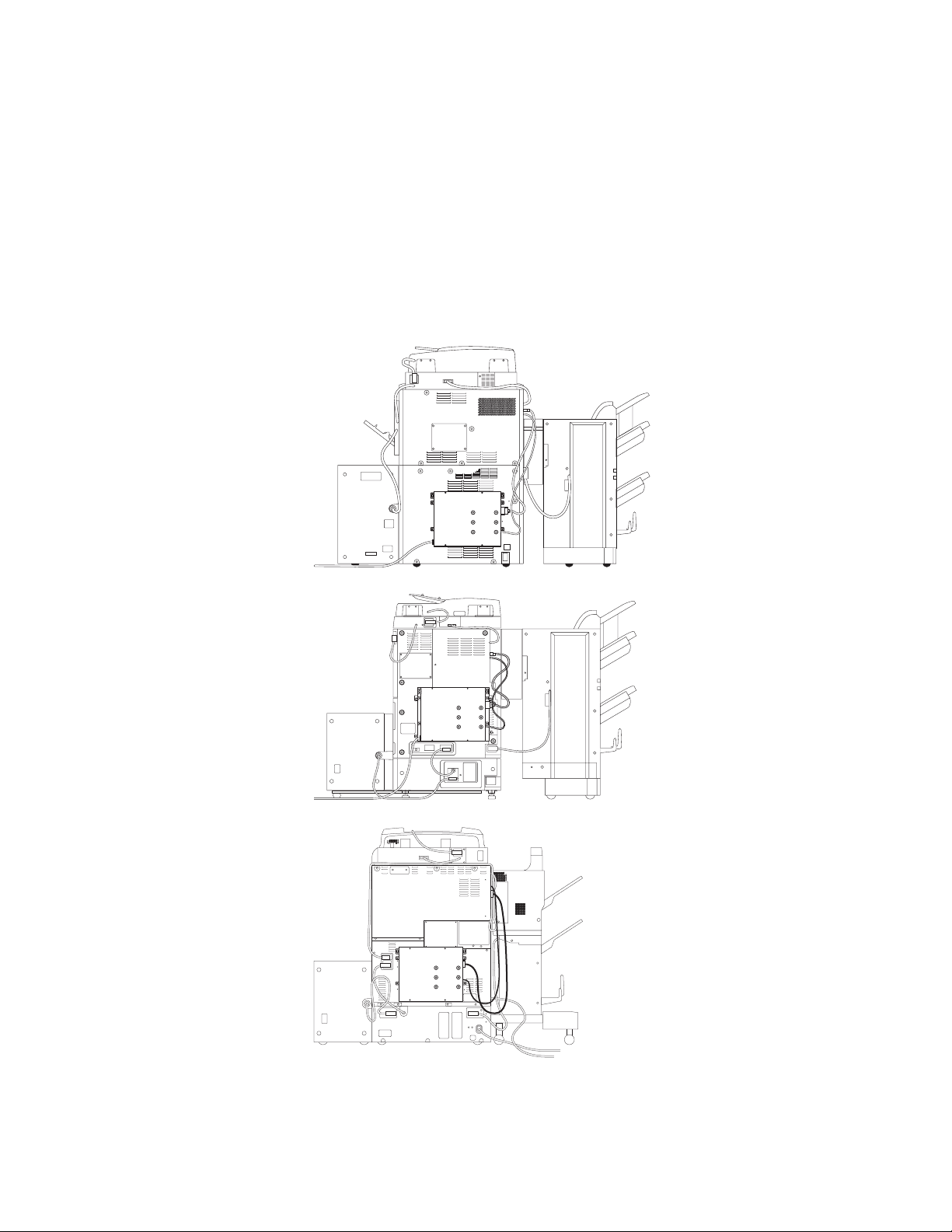
Accessing the Unit-G1/F2/C2
Accessing the Unit-G1/F2/C2
To service the Unit-G1/F2/C2, you must power off and unplug the print engine and
remove the Unit-G1/F2/C2 from the print engine back panel (or mounting bracket if
there is one). Open the lid of the Unit-G1/F2/C2. If there is a mounting bracket in your
configuration, you do not need to remove the mounting bracket from the print engine
back panel.
N
OTE
:
Detailed Unit-G1/F2/C2 installation instructions are not provided in this guide.
Unit-F2
with mounting
bracket
Unit-C2
IGURE
F
6
Unit-G1/F2/C2 attached to their respective print engines
B
Page 13
Checking connections
IGURE
F
Mounting bracket for Unit-F2
C
Checking connections
The most common causes of hardware problems are faulty or loose connections. Make
sure that Unit-G1/F2/C2 cables are intact and that both ends of each cable are properly
aligned and well seated on the appropriate connectors.
External connections
Connectors for external cables are located on the connector panel, and a power cord is
located at the back of the Unit-G1/F2/C2. Check the Unit-G1/F2/C2 power cord and
then check all external cables at the Unit-G1/F2/C2 connector panel (see the following
figure). Also check the positions of the two switches on the connector panel.
7
Page 14
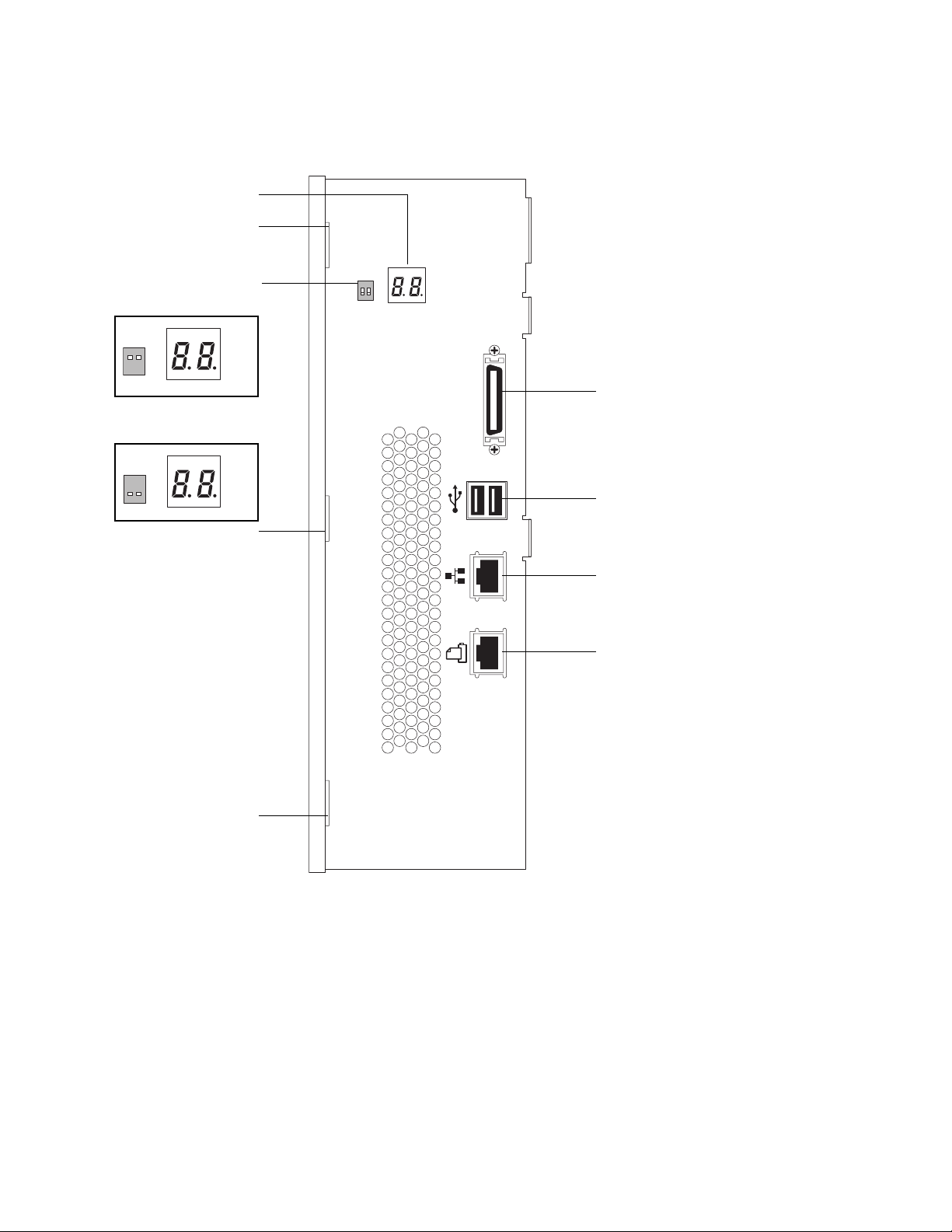
DIAG 2-digit LEDs
Tab slot
Checking connections
DL switches
Service position (up):
DL
1 2
Normal position (down):
DL
1 2
Tab slot
DIAG
DIAG
DL
DIAG
Print Engine interface connector
VIDEO
USB-A ports (2)
10BaseT/100BaseTX/1000BaseT
connector for twisted pair Ethernet
Print Engine interface connector
Tab slot
D
IGURE
F
Unit-G1/F2/C2 connector panel
After you conclude that all external connections are good, check the internal
connections.
Internal connections
Check the internal connections according to the procedure on page 10. See Figure E on
page 9 for locations of most internal connections. For the HDD, see Figure H on
page 16.
8
Page 15
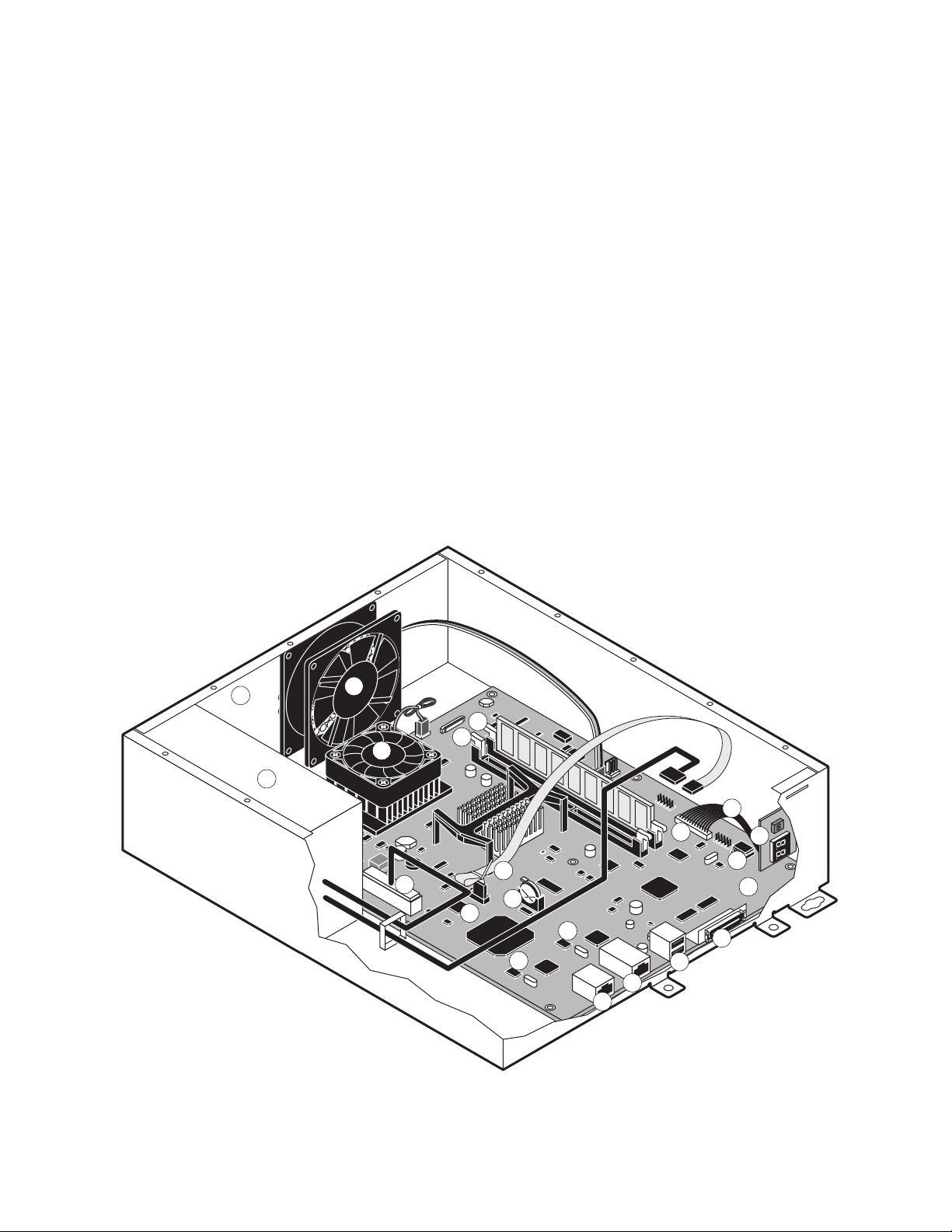
Checking connections
Key (For details on HDD cabling, see Figure G on page 15 and Figure H on page 16.)
1. Chassis
2. Enclosed fan to motherboard ENC FAN1 5V
3. Power supply to motherboard J8008 and to HDD (HDD in lid not shown)
4. CPU cooling assembly to motherboard CPU FAN 5V
5. DDR DIMM2 socket (with standard DIMM)
6. DDR DIMM1 socket (for optional upgrade)
7. BIOS (U530)
8. MAC chip set (ENET EEPROM): 8a U7701; 8b U5060
9. Battery in socket (BT300)
10. Unit-G1/F2/C2 motherboard
11. Print Engine interface connectors
12. RJ-45 network connector
13. USB-A ports (2)
14. Port 80 board with DIAG 2-digit LEDs and Download (DL) switches
15. Port 80 cable
16. PORT80 connector
17. Key chip (U7201)
18. Power connector (J8008)
19. HDD SATA cable at motherboard connector SATA0
IGURE
F
2
4
18
Chassis components
E
5
6
15
16
19
9
7
8b
8a
12
11
13
14
17
10
11
1
3
9
Page 16

T
O
CHECK
Checking connections
INTERNAL
CONNECTIONS
AUTION
C
Before you touch any parts inside the print engine, make sure to wear an ESD
:
grounding wrist strap.
1. Make sure that any Unit-G1/F2/C2 cables, boards, and DIMMs are intact, properly
aligned, and well seated in their connectors (see Figure G on page 15 and Figure H on
page 16).
•Hard disk drive (HDD) and HDD SATA cable
• DIMM
•Enclosed fan and cable
• CPU cooling assembly and fan cable
• PORT 80 board and cable
•Power supply and cables
2. After verifying connections, if one or more Unit-G1/F2/C2 components are still not
getting power, check again:
• The two interface cable connections between the Unit-G1/F2/C2 and the print engine
• The print engine power supply (see the documentation that accompanies the
print engine)
10
Page 17

Checking connections
Power scheme
The Unit-G1/F2/C2 has its own power supply and AC power cable. To function, the
Unit-G1/F2/C2 must be connected to the print engine and to a proper AC power outlet.
The Unit-G1/F2/C2 will not start up until the print engine is powered on. Powering off
the print engine powers off the Unit-G1/F2/C2 also.
When you power off the print engine, the Unit-G1/F2/C2 takes awhile to shut down
and power off. Always check the DIAG LEDs on the connector panel of the Unit-G1/
F2/C2: when the LEDs go out, the Unit-G1/F2/C2 is off.
The Unit-G1/F2/C2 power supply supplies power directly to the motherboard and to
the HDD. From the motherboard, power goes to the PORT 80 board and the enclosed
fan (see Figure G on page 15 and Figure H on page 16).
The Unit-G1/F2/C2 powers off and on by means of the print engine power switch. The
Unit-G1/F2/C2 shuts down if it is disconnected from the print engine. In normal usage,
the customer can leave the Unit-G1/F2/C2 plugged in to the AC power outlet and
connected to the print engine.
Before you perform service on the Unit-G1/F2/C2 hardware:
•Power off the Unit-G1/F2/C2 using the print engine power switch
•Unplug the Unit-G1/F2/C2 from the AC power outlet
•If you plan to open the Unit-G1/F2/C2 while it is connected to the print engine ( not
recommended ), make sure also to unplug the print engine from its AC power outlet
before you open the Unit-G1/F2/C2.
11
Page 18
Replacing the Unit-G1/F2/C2 motherboard
Replacing the Unit-G1/F2/C2 motherboard
When the Unit-G1/F2/C2 motherboard needs to be replaced, use the following
procedures.
T
U
O
SHUT
DOWN
THE
G1/F2/C2
NIT-
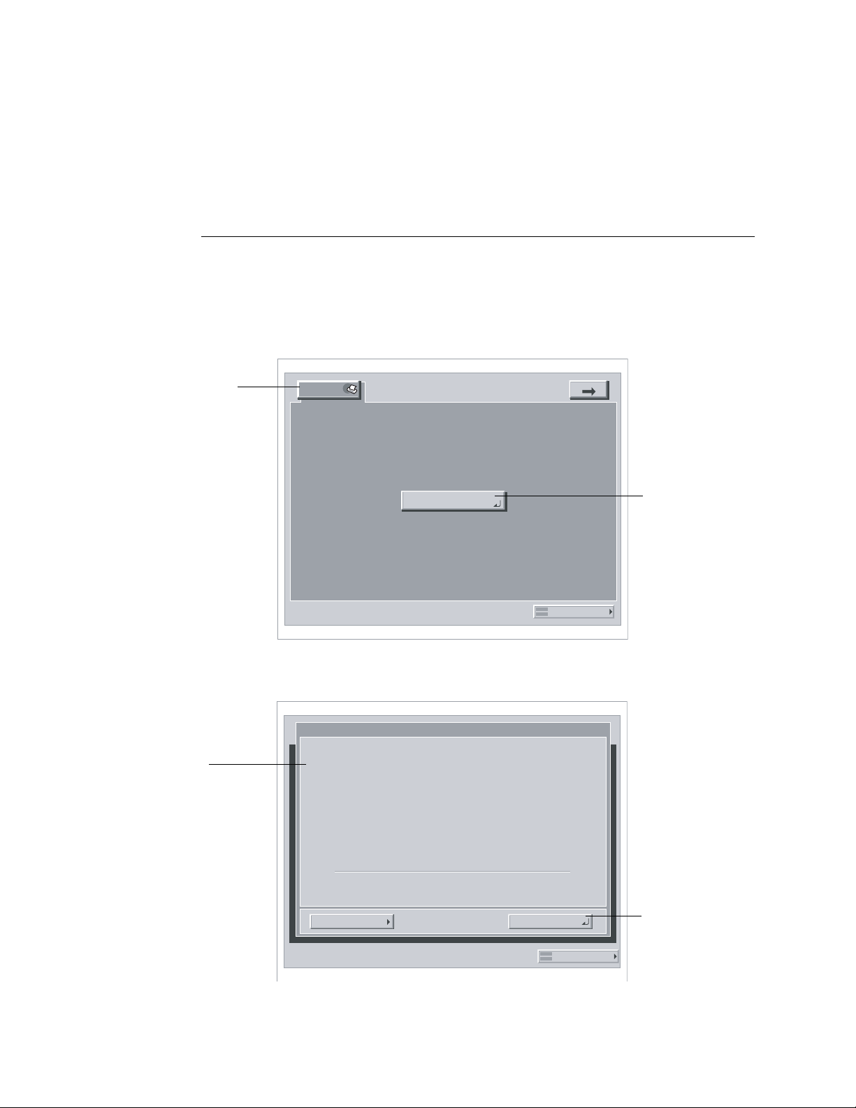
1. If the print engine is in its main mode, select the Printer tab on the print engine LCD
and then select Printer Status/Setting.
Depending on the number of feature tabs, you may need to press the arrow key to display
the screen with the Printer tab.
FROM
THE
PRINT
ENGINE
LCD
Printer tab
Idle appears on the
print engine LCD
Printer
Printer Status/
Settings
Online...Scanner
System Monitor
Printer Status/
Settings
2. Make sure that the Unit-G1/F2/C2 is idle (not processing) and select Functions from the
info screen.
Info
xxxxx
Idle
x.xx
12
xxxxMB
FunctionsDone
System Monitor
Functions
Page 19
Replacing the Unit-G1/F2/C2 motherboard
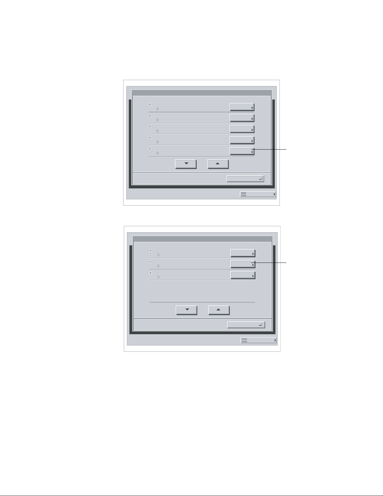
3. Select Shut Down from the Functions screen.
Functions
Print Pages
Scan Job
Suspend Printing
Resume Printing
Shut Down
1/2
DONE
System Monitor
4. Select Shut Down System from the Shut Down screen.
Shut Down
Restart System
Shut Down System
Reboot System
1/1
DONE
Shut Down
Shut Down System
System Monitor
5. After a message that it is safe to power off the system is displayed, power off the
Unit-G1/F2/C2 using the print engine power switch.
OTE
If you are recycling power, wait at least 45 seconds before powering back on.
N
:
13
Page 20
Replacing the Unit-G1/F2/C2 motherboard
TO OPEN THE UNIT- G1/F2/C2
CAUTION: Make sure you use an ESD grounding wrist strap and follow standard ESD
(electrostatic discharge) precautions while performing this procedure.
1. Shut down the Unit-G1/F2/C2 as described on page 12.
2. Unplug the print engine and remove the Unit-G1/F2/C2.
For information about removing the Unit-G1/F2/C2 from the print engine, see the
Unit-G1/F2/C2 installation instructions, not provided in this guide.
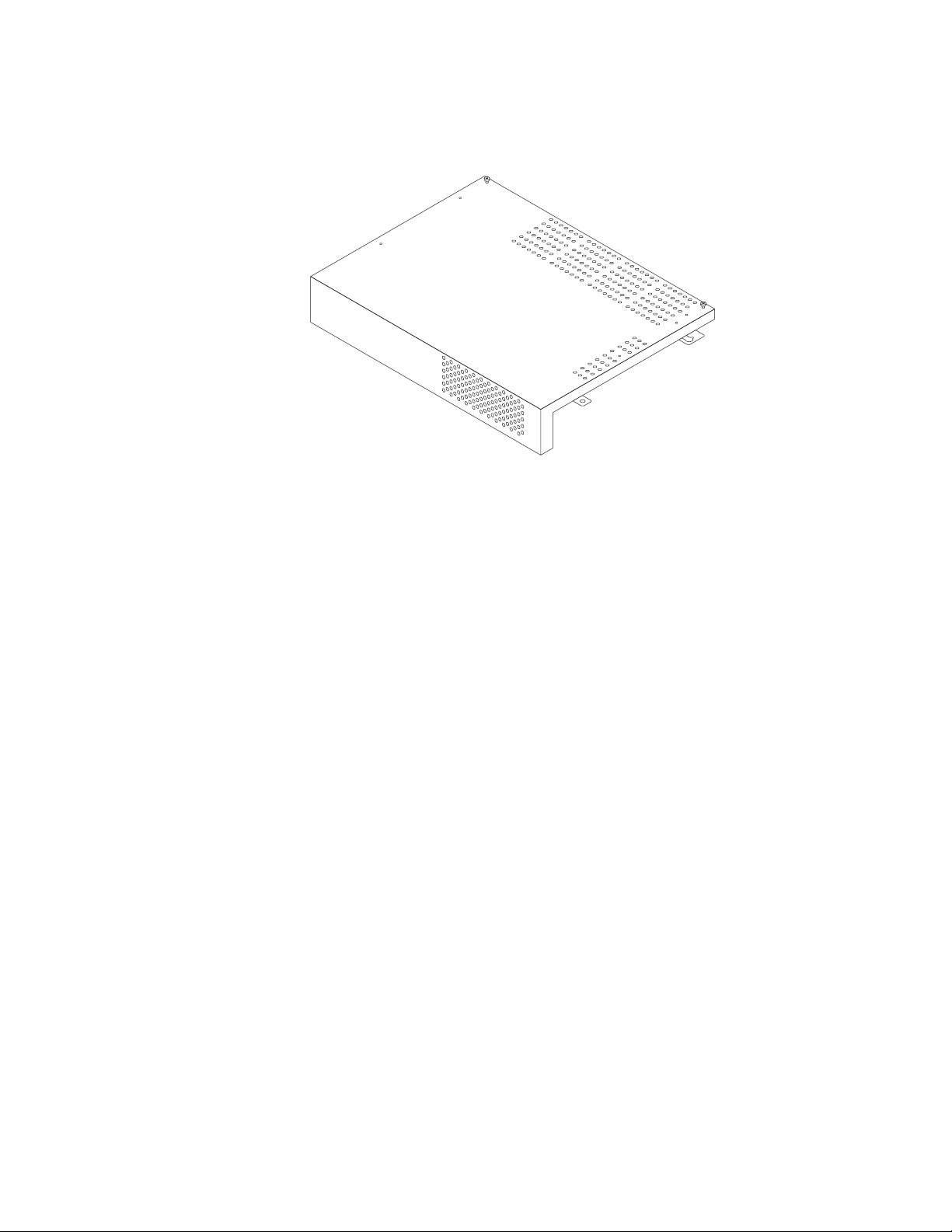
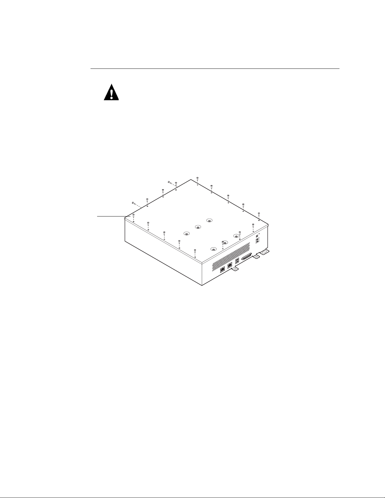
3. Position the Unit-G1/F2/C2 so that the screw holes in the lid are facing up.
4. Remove the 18 screws that secure the lid to the Unit-G1/F2/C2 and set them aside.
Lid
14
F
IGURE F Unit-G1/F2/C2 lid screws
Page 21

Lid
HDD
Replacing the Unit-G1/F2/C2 motherboard
5. Lift up the lid, hold it in a vertical position, and disconnect the cables (2) from the
HDD.
Make sure to hold the lid so that it does not fall. The HDD is mounted to the lid and is
connected to the motherboard and power supply by short cables. Do not stress the cables
and connectors by opening the lid past a vertical position.
HDD cable in
motherboard
connector SATA0
(See note on
page 31)
Motherboard
HDD SATA power cable
Power supply
FIGURE G Internal components
6. Slide the lid sideways to unhook the three tabs from the chassis (for tab slot locations
see Figure D on page 8).
15
Page 22

Power supply
Replacing the Unit-G1/F2/C2 motherboard
7. Gently set the lid upside down on a flat anti-static surface.
Enclosed fan cable
in FAN
HDD cable in SATA0
(See note on page 31)
Power supply cable
for motherboard in
J8008
Power supply cable
for HDD
HDD
F
IGURE H Accessing the Unit-G1/F2/C2
TO REMOVE THE UNIT-G1/F2/C2 MOTHERBOARD
CAUTION: Make sure you use an ESD grounding wrist strap and follow standard ESD
(electrostatic discharge) precautions while performing this procedure.
1. Shut down and open the Unit-G1/F2/C2 as described on page 12 and page 14.
2. Disconnect the following cables from the motherboard (see Figure H).
Port 80 board
cable connector
16
•Enclosed fan cable at motherboard FAN connector
• PORT 80 board cable at motherboard PORT 80 connector
• HDD cable at motherboard SATA0 connector
•Power supply cable at motherboard J8008 connector
3. Remove the 7 screws that secure the motherboard to the chassis and the 2 screws that
secure the motherboard to the connector panel.
The screw types differ. Keep like screws together.
4. Pinch the locks on any locking standoffs to release the motherboard from the chassis.
Avoid stressing or flexing the motherboard and avoid scraping any components.
5. Carefully remove the motherboard from the connector panel cutouts. Lift the
motherboard out of the chassis and set it on a flat anti-static surface.
Page 23

Replacing the Unit-G1/F2/C2 motherboard
TO REPLACE THE MOTHERBOARD IN THE CHASSIS
1. If you are replacing an old motherboard with a new motherboard, unpack the new
motherboard and install the following components from the old motherboard, because a
spare motherboard does not have these components:
• DIMM (see page 19)
•Key chip in U7201 (see page 21)
Edge connectors
DIMM
Key chip U7201
For the appropriate marking, see the information
provided in Figure A on page 5
Connector panel cutouts
[Chassis not shown]
FIGURE I Motherboard
2. Insert the edge connectors into the chassis connector panel and align the motherboard
screw holes with the standoffs in the chassis.
Avoid stressing or flexing the motherboard and avoid scraping any components.
3. Align the motherboard with any locking standoffs and snap into place.
4. Install the screws that secure the motherboard to the connector panel and to the chassis.
Tip: To prevent stress on the motherboard, tighten the two connector panel screws first;
then tighten the screws to the chassis.
5. Connect the following cables to the motherboard (see Figure H on page 16):
•Enclosed fan cable at motherboard FAN connector
• PORT 80 board cable at motherboard PORT 80 connector
• HDD cable at motherboard SATA0 connector
•Power supply cable at motherboard J8008 connector
6. Reassemble the unit and verify functionality (see page 31).
17
Page 24

Replacing Unit-G1/F2/C2 components
Replacing Unit-G1/F2/C2 components
The CPU on the custom Unit-G1/F2/C2 controls the printing image data transferred to
and from the print engine. The Unit-G1/F2/C2 provides the Ethernet networking
interface, controls hard disk drive (HDD) functions, and handles the communication
with external devices. The Unit-G1/F2/C2 has two DIMM sockets that each hold
256MB of memory (see Figure E on page 9). The HDD is attached to the inside lid and
connects to the motherboard and power supply by cables (see Figure A on page 5).
When the Unit-G1/F2/C2 is installed inside the print engine, the connectors for external
devices are easily accessible from the back of the print engine.
This section describes how to remove and install components on the Unit-G1/F2/C2:
• DIMM
• BIOS
•Socketed chips (Key chip; Mac chip set)
(If you replace the motherboard, it is not necessary to transfer the BIOS or the Mac
chip set from the old motherboard. It is necessary to transfer the Key chip.)
•Battery
• CPU cooling assembly
•Enclosed fan
•Power supply
• PORT 80 board
• HDD
CAUTION: Make sure to use an ESD grounding wrist strap and follow standard ESD
(electrostatic discharge) precautions while performing these procedures.
18
Page 25

Replacing Unit-G1/F2/C2 components
DIMM
The memory capacity for the Unit-G1/F2/C2 is 512MB. The standard configuration is
one 256MB DIMM installed in the outer socket, DDR DIMM2. To upgrade, install
another 256MB DIMM in the inner socket, DIMM1 (see page 9).
A DIMM (dual in-line memory module) is held in place by levers at each end of its
socket on the Unit-G1/F2/C2.
Approved DIMMs are available from your authorized service support center.
TO REPLACE OR UPGRADE A DIMM
1. To release a DIMM, push outward on the lever on each side of the DIMM (see Figure J).
Lever
DIMM
Socket notch
F
IGURE J Releasing a DIMM
2. Slide the DIMM straight out of the socket to avoid damaging the DIMM or the socket, and
set the DIMM aside.
3. To install a DIMM, insert it straight into the socket. Push the DIMM into the socket until
the levers snap into place.
The DIMM fits the socket only one way. The notch on the bottom of the DIMM should
line up with the notch in the socket.
Make sure that the levers close securely around the ends of the DIMM and that the
DIMM is fully seated in its socket. Avoid flexing the board while you firmly seat the
DIMM in its socket.
4. Reassemble the unit and verify functionality (see page 31).
To verify memory capacity, print a Configuration page to check the amount of memory
recorded.
19
Page 26

Replacing Unit-G1/F2/C2 components
BIOS chip
The BIOS chip is located in the PLCC32 socket on the motherboard at U530 (see
Figure E on page 9). The BIOS chip contains boot information. If you must install a
BIOS chip, use the following procedure. For installing other socketed chips, see page 21.
NOTE: It is not necessary to transfer the BIOS chip when replacing the motherboard.
TO INSTALL THE BIOS CHIP
1. Locate the motherboard PLCC32 socket (U530).
2. If a BIOS chip is already installed in the socket, remove it gently, using a PLCC extractor
(not provided).
Make sure not to put stress on surrounding components or connectors.
Socket Notch
PLCC Extractor
U
BIOS
Chip
U
FIGURE K BIOS chip in socket
3. Place the required BIOS chip on the socket so that the notch in the chip is aligned with
the notch in the socket. Press down on the chip until it snaps into place.
4. Reassemble the Unit-G1/F2/C2 and verify its functionality (see “Restoring functionality
after service” on page 31).
20
Page 27

Replacing Unit-G1/F2/C2 components
Socketed chips
Use the following procedure if you must install one or more of the following socketed
chips:
•Key chip at U7201
•MAC chip set at:
• U7701 for print engine
• U5060 for LAN
NOTE: It is not necessary to transfer the Mac chip set when replacing the motherboard.
TO INSTALL A SOCKETED CHIP
1. Locate the appropriate motherboard socket (see Figure L).
MAC chip set: U7701
MAC chip set markings:
EF (Orange) = U7701 (print engine)
EE (White) = U5060 (LAN)
2. If a chip is already installed, remove it gently using a PROM extractor (not provided).
3. Place the required chip on its socket so that the notch in the chip is aligned with the
4. Reassemble the Unit-G1/F2/C2 and verify its functionality (see page 31).
Key
chip:
U7201
U5060
FIGURE L Socketed chips
Make sure not to put stress on surrounding components or connectors.
notch in the socket. Press down on the chip until it connects firmly into place.
Make sure to align the pins on the chip with the holes in the socket. If you notice any
bent pins, straighten them gently with a pair of needlenose pliers.
N
OTE: If you must install a different MAC chip set onto the motherboard, the system
administrator may need to reconfigure the IP address in Setup. (For instructions, see
Configuration and Setup, on the User Documentation CD.)
21
Page 28

Replacing Unit-G1/F2/C2 components
Battery
The battery on the Unit-G1/F2/C2 is located at BT300. To replace it, see
“Specifications” on page 45.
CAUTION: There is danger of explosion if the battery is replaced with the incorrect type.
Replace it only with the same type recommended by the manufacturer. Dispose of used
batteries according to the manufacturer’s instructions.
ACHTUNG: Es besteht Explosionsgefahr, wenn die Batterie durch eine Batterie falschen Typs ersetzt wird. Als Ersatz dürfen
nur vom Hersteller empfohlene Batterien gleichen oder ähnlichen Typs verwendet werden. Verbrauchte Batterien müssen
entsprechend den Anweisungen des Herstellers entsorgt werden.
ATTENTION: Il y a risque d’explosion si la pile est remplacée par un modèle qui ne convient pas. Remplacez-la
uniquement par le modèle recommandé par le constructeur. Débarrassez-vous des piles usées conformément aux instructions
du constructeur.
ADVARSEL!: Lithiumbatteri - Eksplosionsfare ved fejlagtig håndtering Udskiftning må kun ske med bat-teri af samme
fabrikat og type. Levér det brugte batteri tilbage til leverandøren.
VAROITUS: Paristo voi räjähtää, los se on virheellisesti asennettu. Vaihda paristo ainoastaan laitevalmistajan suosittelemaan
tyyppiin. Hävitä Käytetty paristo valmistajan ohjeiden mukaisesti.
ADVARSEL: Eksplosjonsfare ved feilaktig skifte av batteri. Benytt samme batteritype eller en tilsvarende type anbefalt av
apparatfabrikanten. Brukte batterier kasseres i henhold til fabrikantens instruksjoner.
VARNING: Explosionsfara vid felaktigt batteribyte. Använd samma batterityp eller en ekvivalent typ som rekommenderas
av apparat-tillverkaren. Kassera använt batteri enligt fabrikantens instruktion.
TO REPLACE THE MOTHERBOARD BATTERY
1. Pull the old battery out of its socket (see Figure M) and insert the new battery.
Battery
Socket
IGURE M Motherboard battery
F
2. Reassemble the Unit-G1/F2/C2 and verify its functionality as described on page 31.
N
OTE: When you power on the print engine, allow the Unit-G1/F2/C2 to reach Idle,
then power off and on again to reinitialize the realtime clock. Wait 45 seconds between
power off and power on.
Motherboard
22
3. Configure the time and date in Setup.
Page 29

TO REPLACE THE CPU COOLING ASSEMBLY
To CPU FAN 5V connector
Cooling assembly
Tension screw
(1 of 4)
Replacing Unit-G1/F2/C2 components
CPU cooling assembly
The CPU cooling assembly consists of a heatsink and fan for dissipating heat generated
by the CPU. If it stops functioning, the Unit-G1/F2/C2 will shut down automatically.
1. Shut down and open the Unit-G1/F2/C2 as described on pages 12 and 14.
2. Remove the motherboard from the chassis as described on page 18.
3. Disconnect the fan cable from the motherboard CPU FAN 5V connector.
F
IGURE N CPU cooling assembly and fan connection
4. Pinch each of the four tension screws on the underside of the motherboard to detach the
CPU cooling assembly from the motherboard.
When replacing the fan, make sure to install it in its original orientation.
5. Align the new CPU cooling assembly over the CPU and then push the four tension screws
through the motherboard screw holes until they snap into place.
6. Connect the fan cable to the motherboard CPU FAN 5V connector.
The motherboard connector is keyed so that the cable fits only one way.
7. Install the motherboard into the chassis as described on page 17.
8. Reassemble the unit and verify functionality as described on page 31.
23
Page 30

Replacing Unit-G1/F2/C2 components
Enclosed fan
One enclosed fan cools the system by blowing air out the back of the chassis (see Figure E
on page 9). If it stops functioning, the Unit-G1/F2/C2 will shut down automatically.
TO REPLACE AN ENCLOSED FAN
1. Shut down and open the Unit-G1/F2/C2 as described on pages 12 and 14.
Enclosed fan
Front view
24
Rivet (1 of 4)
Back view
2. Disconnect the fan cable from the motherboard ENC FAN1 5V connector.
3. Remove the 4 rivets that secure the fan to the chassis and remove the fan.
Tip: Press the rivet from inside the chassis in order to dislodge the rivet easily.
4. Secure the new fan inside the chassis using the rivets you removed. Make sure the new
fan is in the same orientation as the old fan.
When replacing the fan, make sure to install it such that the air will blow out the back of
the chassis.
5. Connect the fan cable to a motherboard ENC FAN1 5V connector.
6. Reassemble the unit and verify functionality as described on page 31.
Page 31

Replacing Unit-G1/F2/C2 components
Power supply
The Unit-G1/F2/C2 has its own dedicated power supply. To remove and/or replace it,
use the following procedures and refer to the following figure.
Power supply
To motherboard connector J8008
Routing clamp
OTE: The power supply includes two identical HDD
ATA power cables. If one breaks, use the other one.
FIGURE O Power supply cables
TO REMOVE THE POWER SUPPLY
CAUTION: Make sure you wear an ESD grounding wrist strap and follow standard ESD
(electrostatic discharge) precautions while handling Unit-G1/F2/C2 components.
To HDD SATA power
connector (HDD in lid
is not shown)
1. Shut down and open the Unit-G1/F2/C2 as described on pages 12 and 14.
2. Remove the power supply cable from motherboard connector at J8008.
(You already removed the HDD SATA power cable from the HDD.)
3. Take the power supply cables out of any routing clamps that are attached to the chassis.
Note the routing so that you can route the cables correctly later.
4. Remove the screws that secure the power supply to the chassis: 3 to the back; 1 to the
bottom (through the power supply bracket). See Figure A on page 5 for locations.
Set the screws aside so you can replace them later.
5. Remove the power supply from the chassis.
NOTE: If you will be installing a new power supply you may need to transfer the power
supply bracket from the old power supply to the new power supply (2 screws).
25
Page 32

Replacing Unit-G1/F2/C2 components
TO REPLACE THE POWER SUPPLY
CAUTION: Make sure you attach an ESD grounding wrist strap and follow standard ESD
(electrostatic discharge) precautions before handling Unit-G1/F2/C2 components.
1. Position the power supply in the chassis (see Figure O on page 25).
2. Secure the power supply to the chassis with the 4 screws you removed earlier: 3 to the
back; 1 to the bottom (through the power supply bracket). See Figure A on page 5.
3. Insert the power supply cables into the one or more routing clamps.
Routing clamps keep the cables away from system components as much as possible.
4. Connect the power supply cable to the motherboard at power connector J8008.
Lid
4-pin power connector
NOTE: Keep the tie-wrap in place.
[not used]
HDD cable at
motherboard
connector SATA0
(See note below)
Tie-wrap
Motherboard
The tie-wrap is required to keep a bend in the
HDD cable in order to avoid stressing the SATA0
connector when the lid is closed.
F
IGURE P Replacing the power supply
5. Reassemble the unit and verify functionality (see page 31).
N
OTE: When you attach the HDD SATA power cable to the HDD, make sure to keep
the tie-wrap in place on the HDD SATA power cable. The tie-wrap is required to protect
the motherboard connector SATA0 when the lid is closed.
HDD
HDD SATA power cable
Routing clamp
Power supply
Screw to back (1 of 3)
For location of 1 screw to
bottom, see page 5.
26
Page 33

Replacing Unit-G1/F2/C2 components
PORT 80 board
The Unit-G1/F2/C2 uses a PORT 80 board to offer service mode switches for installing
system software over the network and DIAG LEDs arrayed as a 2-digit display. To
remove and/or replace it, use the following procedures and refer to the following figure.
Port 80 cable
to PORT80
connector
Port 80 board
Snap rivet
(1 of 4)
FIGURE Q Cable to PORT 80 board
TO REMOVE THE PORT 80 BOARD
CAUTION: Make sure you wear an ESD grounding wrist strap and follow standard ESD
(electrostatic discharge) precautions while handling Unit-G1/F2/C2 components.
1. Shut down and open the Unit-G1/F2/C2 as described on pages 12 and 14.
2. Remove the Port 80 board cable from the motherboard PORT 80 connector.
Do not pull the wires of the cable. Pull the cable out by its connector.
3. Remove the snap rivets that secure the Port 80 board to the connector panel of the
chassis and remove the Port 80 board.
You may need pliers to squeeze the end of the rivet while you push the rivet through the
board and chassis. Set the rivets aside so you can replace them later.
TO REPLACE THE PORT 80 BOARD
CAUTION: Make sure you attach an ESD grounding wrist strap and follow standard ESD
(electrostatic discharge) precautions before handling Unit-G1/F2/C2 components.
1. Position the PORT 80 board in the chassis (see Figure Q on page 27) and secure the PORT
80 board to the chassis with the snap rivets you removed earlier.
2. Connect the Port 80 board cable to the PORT 80 board and to the motherboard PORT 80
connector.
3. Reassemble the unit and verify functionality (see page 31).
27
Page 34

Replacing Unit-G1/F2/C2 components
Hard disk drive
The factory-installed hard disk drive (HDD) is formatted and loaded with all Unit-G1/
F2/C2 software, including operating software, system software, network drivers, and
printer fonts. Because the HDD is used to store spooled print jobs, available disk space is
displayed on the print engine LCD.
If the HDD needs to be replaced, you will need to install the system software on the new
one. (Replacement drives are shipped without Unit-G1/F2/C2 system software
installed.) For more information, see “System software” on page 35.
Proper handling
Handle the HDD with care:
•Use proper ESD practices when grounding yourself and the Unit-G1/F2/C2.
•Keep magnets and magnetic-sensitive objects away from the HDD.
•Do not remove the screws on top of the HDD. Loosening these screws voids the
warranty.
•Never drop, jar, or bump the HDD.
•Handle the HDD by its sides and avoid touching the printed circuit board.
• Allow the HDD to reach room temperature before installation.
HDD problems may be a result of the following:
• Loose or faulty connection
•Faulty HDD
Before you decide that the HDD needs to be replaced, make sure that the cables to the
HDD are intact and connected properly. See Figure R on page 29.
To remove and/or replace the HDD, use the following procedures and refer to the
following figures.
28
Page 35

TO REMOVE THE HDD
Lid
4-pin power connector [not used]
To motherboard SATA0 connector
Replacing Unit-G1/F2/C2 components
CAUTION: Make sure you wear an ESD grounding wrist strap and follow standard ESD
(electrostatic discharge) precautions while handling Unit-G1/F2/C2 components.
1. Shut down and open the Unit-G1/F2/C2 as described on pages 12 and 14.
Chassis
NOTE: Disconnect the HDD cables from the HDD
before you remove the lid from the chassis (see
page 16).
F
IGURE R HDD cables and connectors
2. After removing the lid from the chassis, remove the HDD from the shock bracket (4
screws). Set the screws aside (see Figure S on page 30).
It is not necessary to remove or disassemble the shock bracket.
From power supply
29
Page 36

Replacing Unit-G1/F2/C2 components
Shock bracket
NOTE: It is not necessary to disassemble and
remove the shock bracket from the lid.
IGURE S HDD and shock bracket
F
3. Place the HDD in an antistatic bag.
Do not touch the HDD with magnetic objects, such as magnetic screwdrivers. Do not
place items near the HDD that are sensitive to magnets, such as credit cards and
employee ID cards. See “Proper handling” on page 28.
HDD
Screw (1 of 4)
Screw hole
(1 of 4)
TO REPLACE THE HDD
CAUTION: Make sure you attach an ESD grounding wrist strap and follow standard ESD
(electrostatic discharge) precautions before handling Unit-G1/F2/C2 components.
1. Handle the HDD with care.
Do not touch it with magnetic objects or place any objects near it that are sensitive to
magnets. See “Proper handling” on page 28.
2. Secure the HDD to the shock bracket using the 4 screws you removed earlier (see
Figure S).
3. Reassemble the unit and verify functionality (see page 31).
After you reattach the chassis lid, hold the lid in a vertical position while you reconnect
the HDD cables from motherboard SATA0 connector and from the power supply.
The connectors are keyed for proper orientation of the cables. Note that the 4-pin power
connector is not used. See Figure R on page 29.
Tip: The power supply includes two identical HDD SATA power cables but you only
need one. If one breaks, use the other one.
30
Page 37

Restoring functionality after service
Restoring functionality after service
To complete service procedures performed on the Unit-G1/F2/C2, install the Unit-G1/
F2/C2 inside the print engine as described in the Unit-G1/F2/C2 installation
instructions (not provided in this guide) and verify that it is working properly. To verify
the installation, check the connections of the Unit-G1/F2/C2 first to the print engine
and then to the network.
TO REASSEMBLE AND VERIFY THE UNIT- G1/F2/C2
1. Reseat any boards, cables, connectors, and other parts of the Unit-G1/F2/C2 that you
loosened or removed during inspection or service. (Exception: Do not connect cables to
the HDD until step 2).
2. Install the lid and connect the HDD cables—Insert the three tabs into the tab slots on
the connector panel (see Figure D on page 8); hold the lid vertically while connecting
the cables to the HDD (see Figure R on page 29); close the lid over the chassis and
secure the lid to the chassis with the 18 screws you removed earlier (see Figure F on
page 14).
3. Install the Unit-G1/F2/C2 in the print engine and reassemble the print engine as
described in the Unit-G1/F2/C2 installation instructions (not provided in this guide).
4. If you installed a new HDD, install system software (see “System software” on page 35.)
A spare HDD is shipped without system software.
5. Before you leave the customer site, verify Unit-G1/F2/C2 operation as described in the
following flow diagram.
Power up and print Unit-G1/F2/C2
Test Page (see page 32).
Connect the Unit-G1/F2/C2 to the
network and verify (see page 33).
Check the Setup options (see
Configuration and Setup).
F
IGURE T Steps to verify Unit-G1/F2/C2 connection
Printing Unit-G1/F2/C2 pages
The print engine LCD allows you to print special pages from the Unit-G1/F2/C2. These
pages include the Configuration page and the Test Page.
31
Page 38

Printing Unit-G1/F2/C2 pages
Printing the Configuration page
The Configuration page lists all the settings in effect from the current Setup. After you
have finished running Setup, print a Configuration page to confirm your settings. If the
Unit-G1/F2/C2 is rebooting, allow the Unit-G1/F2/C2 to reboot and return to Idle
before printing a Configuration page.
Before you perform any service procedure, print the Unit-G1/F2/C2 Configuration page
(if possible) so that you are prepared to return the settings to their former configurations,
if necessary.
After the connection to the network is made, the network administrator can customize
Setup options according to the network and user environment. Using the Configuration
page as a guide helps speed up this process. For more information, see
Configuration and Setup, on the User Documentation CD.
Printing the Test Page
Before connecting the Unit-G1/F2/C2 to the network, print the Test Page. The Test Page
is a file that resides in the Unit-G1/F2/C2. Output verifies that the Unit-G1/F2/C2 is
functional and connected properly to the print engine.
TO PRINT UNIT-G1/F2/C2 PAGES FROM THE PRINT ENGINE LCD
1. Select the Printer tab on the print engine LCD, and then select Printer Status/Setting.
2. Select Functions from the print engine LCD.
3. Select Print Pages from the print engine LCD.
4. Select the Test Page, Configuration page, or other page from the Print Pages menu.
5. Examine the Test Page.
If the Test Page prints, you know that the Unit-G1/F2/C2 is functional and that the
connection between the Unit-G1/F2/C2 and the print engine is good. When you
examine the Test Page, keep in mind that:
• All patches should be visible, even though they may be very faint (in the 5% and 2%
range).
• Each patch set should show uniform gradation from patch to patch as the tone lightens
from 100% to 0%.
Poor image quality may indicate a need to calibrate the system or service the
print engine.
6. Post the current Configuration page near the Unit-G1/F2/C2 for quick reference.
Users may need the information on this page which describes the current Setup
configuration.
32
Page 39

Verifying connection to the network
Verifying connection to the network
The Unit-G1/F2/C2 provides twisted pair connectivity to an Ethernet network.
Category 3, category 4, or category 5 unshielded twisted pair (UTP) network cable can
be used for 10BaseT. Category 5 UTP cable must be used for 100BaseTX. See the
following figure and procedure for where to connect and how to verify the network
connection.
Unit-G1/F2/C2 connector
panel
DL
DIAG
VIDEO
Network connector
FIGURE U Unit-G1/F2/C2 network connector
33
Page 40

Verifying connection to the network
TO CONNECT A TWISTED PAIR CABLE TO THE UNIT- G1/F2/C2
1. Shut down and power off the Unit-G1/F2/C2 before connecting the Unit-G1/F2/C2 to any
network device (see “To shut down the Unit-G1/F2/C2 from the print engine LCD” on
page 12).
2. Connect the network cable to the appropriate RJ-45 network connector on the Unit-G1/
F2/C2 connector panel (see Figure U on page 33).
3. Configure Setup options.
It is the network administrator’s responsibility to configure Setup according to the
network and user environment. Default settings in Setup may be adequate although they
may not be optimal for the user’s environment. For setup information, refer the network
administrator to Configuration and Setup, on the User Documentation CD.
4. After configuring Setup options, verify the network connection.
Once the network connection has been made and the Unit-G1/F2/C2 has the correct
Setup configuration and is Idle, the Unit-G1/F2/C2 should be available on the network.
The network administrator should perform any additional network Setup, verify the
network connection, verify that the Unit-G1/F2/C2 appears in the list of printers, and
print a few test documents from a networked computer that will use the Unit-G1/F2/C2.
(For more information, see Configuration and Setup, on the User Documentation CD.)
34
Page 41

System software
System software
The Unit-G1/F2/C2 system software is installed on the HDD at the factory. You must
install system software if a more recent version is required, if you replace the HDD, or if
you discover problems with the current system. To upgrade to a newer version of system
software, you can install all system software over the LAN port or use a USB flash drive.
System software installation reminders
Keep in mind the following when installing system software:
• Fonts—Installing system software deletes all fonts that the customer has installed on
the Unit-G1/F2/C2. Only resident fonts will be restored during system software
installation. Fiery Downloader can be used to reinstall additional fonts.
To determine which additional fonts were downloaded to the Unit-G1/F2/C2, print
the Fonts List before you format the HDD and again after you complete the system
software installation. Any fonts not listed after installation must be reinstalled. For
more information, see Utilities, on the User Documentation CD.
•
Language—Screens for installing system software are always displayed in English,
even if the print engine is configured for another language.
• Compatibility—The latest user software must be installed onto all computers that print
to the Unit-G1/F2/C2. Using incompatible versions of the system and user software
may result in system problems.
Installing system software over the network port
The System Software CD contains the system software and Fiery System Software
Installer. To install system software using the LAN port on the Unit-G1/F2/C2, you
need:
•For 100BaseTX—One Category 5 or higher Ethernet cross-over cable
(4-pair/8-wire, short-length)
For 1000BaseT—One Category 5e or higher Ethernet cross-over cable
(4-pair/8-wire, short-length)
•A Windows XP/2000 computer with:
–A CD-ROM drive, built in or attached
–Support for 100BaseTX or 1000BaseT
35
Page 42

System software
TO INSTALL SYSTEM SOFTWARE USING ETHERNET
1. Shut down the Unit-G1/F2/C2 and power off the print engine (see page 12).
2. Disconnect the customer’s LAN from the LAN port. Disconnect anything connected to the
USB-A ports.
Do not disconnect the two interface cables between the print engine and the Unit-G1/
F2/C2.
DL
DIAG
print engine interface port
VIDEO
USB-A ports
LAN port
LAN port
print engine interface port
FIGURE V Disconnecting from the customer’s LAN
3. Connect an Ethernet cross-over cable to the LAN port and to a Windows XP/2000 PC.
DL
DIAG
VIDEO
To print engine
Ethernet cross-over cable
X
To print engine
Windows 2000/XP PC
36
FIGURE W Creating an isolated Ethernet network using a cross-over cable
Tip: To identify a cross-over cable, compare the connectors on the cable. The ribbon
sequence will be identical. A normal cable will not have identical wiring on both ends.
Page 43

Service position (up):
System software
4. Power on the PC and insert the System Software CD into the PC CD-ROM drive.
5. Navigate to the CD-ROM drive and click the icon for the Installer.exe file if it does not
start automatically.
6. If you are prompted to find the install.ini file, navigate to the top level of the CD-ROM
drive. Select the install.ini file and click Open.
7. Click next at the Welcome screen. Read the Software License Agreement and click the “I
Agree” checkbox if you wish to continue the installation process, then click Next.
8. At the Connection Type screen, make sure Ethernet is selected. Click Next to advance to
the Confirmation screen.
9. Flip the Unit-G1/F2/C2 service switches up to the service mode position (see Figure X).
DL
1 2
Normal position (down):
DL
1 2
DIAG
DL switches
DL
DIAG
DIAG
F
IGURE X Switches on the connector panel
After you have finished installing system software, make sure to flip the service switches
down to the normal position.
10. Power on the Unit-G1/F2/C2 using the print engine AC power switch and wait 10
seconds.
To avoid confusion, ignore the text and graphics on this Confirmation screen. The
procedure on this screen may not depict Unit-G1/F2/C2 hardware.
11. Click Next on the PC screen.
37
Page 44

System software
12. At the Installation screen, click Next to commence installation. Wait while the files are
copied and installed.
The progress is slow at first. For most computers, expect to wait approximately 25
minutes to complete—do not cancel.
If you do click Cancel click Finish, and then power off the print engine, wait 10 seconds,
and then repeat this procedure from the beginning. If the installation terminates
abnormally, you may need to reboot the PC also. To avoid confusion, ignore the text and
graphics on the cancel screen.
13. Click Exit when the message is displayed that the installation is successful. Remove the
System Software CD from the PC.
14. Power off the print engine.
15. Flip the service switches down to the normal position (see Figure X).
16. Disconnect the cross-over cable from the LAN port and the Windows XP/2000 PC.
DL
DIAG
LAN port
VIDEO
F
IGURE Y Dismantling the isolated Ethernet network
To print engine
Ethernet cross-over cable
Windows 2000/XP PC
X
To print engine
17. Reconnect the LAN cable that you removed earlier to the Unit-G1/F2/C2 connector
panel.
18. Power on the print engine and wait a few minutes.
19. At the Languages Setup screen, select the name of the language you want to use, and
then select OK. Wait a few minutes.
38
Page 45

System software
20. If the Select Market Region screen is displayed, select the name of the region for the
Unit-G1/F2/C2 and then select OK. Wait a few minutes.
The Select Market Region screen is displayed only if English was selected from the
language selection screen.
NOTE: If you select English as the language, you must then select “UK” or “Other”. If you
select UK, the default paper size is A4 and the time stamp is DD/MM/YY. If you select
“Other” the default paper size is LT and the time stamp is MM/DD/YY.
21. A screen may appear briefly regarding print engine functions. See other documentation
for details.
22. At the Setup screen, select Run Setup and select OK. Reenter the customer’s settings
from the Configuration page that you printed earlier.
Enter settings for Server, Network, and Printer Setup, in that order. Ignore the settings
not included on the Configuration page if it is more appropriate for the site
administrator to set them. For more information, see Configuration and Setup, on the
User Documentation CD.
23. After all setup options are configured, select Exit Setup from the Setup screen, and then
press OK.
The Unit-G1/F2/C2 will reboot with the updated system software and setup options.
24. Allow the Unit-G1/F2/C2 to reach Idle.
39
Page 46

System software
Installing system software using a USB flash drive
To install system software using a USB flash drive attached to the Unit-G1/F2/C2, you
need the following items:
• USB 2.0 flash drive [not provided] with 1 Gigabyte capacity and a data transfer LED
Not all USB 2.0 flash drives have been validated for use with the Unit-G1/F2/C2. If
the one you are using does not work, try another brand.
• Any PC [not provided] with:
–Intel x86-compatible microprocessor
– CD-ROM drive, built in or attached
–Support for USB 2.0
(USB 1.1 may work but may be very slow)
– 256MB, minimum, memory capacity
•System Software CD (if the number of CDs increases to 2 in a subsequent upgrade,
you may need to increase the Gigabyte capacity of the USB 2.0 flash drive to 2GB)
• USB Flash Tool CD
To install system software using a USB 2.0 flash drive, you must use a flash drive that has
been prepared already. The procedures in this section are:
•“To prepare a USB flash drive”
•“To install system software using a prepared USB flash drive”
40
Page 47

System software
TO PREPARE A USB FLASH DRIVE
NOTE: Make sure the boot priority on your PC is set to boot first from the CD-ROM
drive.
To find out how to access/change the PC’s BIOS configuration, see the documentation
that accompanies your PC. Typically, pressing a key during power up (such as F2 or DEL
or F8) will access the BIOS configuration screen.
1. Power on the PC and as soon as the CD-ROM drive LED goes out, load the USB Flash Tool
CD into the PC’s CD-ROM drive.
If you load the CD too late, the PC boots as usual. In that case, restart the PC so that the
PC boots from the CD.
2. Allow the PC to boot from the CD (several minutes, depending on your PC).
Tr oubleshooting tips: If the PC fails to display the Flash Drive Setup screen within 30
minutes, make sure that the PC boot priority is set to boot first from the CD-ROM drive
and make sure that no devices are connected to the USB-A ports. If the PC still fails to
display the Flash Drive Setup screen, try another PC. It could be that your PC is not
compatible with the boot program on the USB Flash Tool CD.
3. Follow the on-screen USB Flash Tool screen prompts. Other status screens may appear
briefly but are not necessarily described here:
N
OTE: To respond to a prompt use only the keyboard, not the mouse.
Screen prompt What you need to do:
1. Please plug in a USB flash drive and
insert a valid product CD, and press OK.
2. Total Number of CD: x
Continue with flash drive setup?
Yes No
3. Flash programming in progress. Please
wait.
The CD-ROM drive door may open and
close automatically during this procedure. If
it does not, manually open and close the
drive door when removing/inserting a CD.
• Connect a USB flash drive to a USB-A
port on the PC
•Remove the USB Flash Tool CD
•Insert the system software CD and
press Enter, then wait.
If the same screen prompt re-appears,
just wait or press Enter again.
•Select Yes
•Wait for the next prompt.
41
Page 48

System software
Screen prompt What you need to do:
4. Copying [filename]...
[Progress bar indicates %]
5. USB flash device is ready for
installation. The device can be safely
removed. OK
6. Do you want to program more USB flash
drives? Yes No
7. System will shutdown. Yes No
8. Processing complete. Please remove CD.
Rebooting...
The following prompt appears at the end of
a list of status messages:
9. Please remove CD. Close cdrom drive
and hit return.
10. Shutdown complete
NOTE: Sometimes system software consists
of more than 1 CD (system software v1.0
for Unit-G1/F2/C2 consists of only 1 CD).
If system software consists of 2 CDs, the
following screen appears after copying the
files from CD 1.
Please insert CD 2 and press OK.
•Wait for the next prompt.
This task usually takes 5-10 minutes,
but may take considerably longer
depending on your PC.
The progress bar reaches 100%; the
Flash drive LED stops flashing and
eventually goes out; and the next
prompt appears...
•Wait until the LED on the flash drive
goes out completely. Wait another 30
seconds. Disconnect the flash drive
from the USB-A port. Press Enter.
•Select No unless you are preparing
more than one USB flash drive.
•Select Yes.
•Remove the system software CD.
•If you have not removed the CD yet,
remove it now. Manually close the
CDROM drive and press Enter.
• Allow the PC to boot to Windows.
Remove CD 1, insert CD 2, and press
Enter.Then if the same screen
reappears, ignore it. It will disappear in
approximately 10 seconds. Then follow
the same sequence of prompts that
appeared for CD 1.
42
Tr oubleshooting tip: If the LED on the USB flash drive fails to light when you connect the
flash drive to the PC, do the following: power off the PC; remove and reinsert the USB
flash drive into the PC; and verify that its LED turns on when the PC is turned on.
4. Label the prepared USB flash drive with identifying information.
For example, copy onto a label tag (1) the product name and (2) the system software
version number that you find printed on the system software CD label. The USB flash
drive is now prepared and can be used to install system software on the Unit-G1/F2/C2.
Page 49

System software
TO INSTALL SYSTEM SOFTWARE USING A PREPARED USB FLASH DRIVE
1. If your USB flash drive is not yet prepared, follow the procedure on page 41.
2. Power off the print engine using its AC power switch.
3. Make sure the following cables are attached to the Unit-G1/F2/C2:
•Interface cables (2) to the print engine
•Power cable to AC outlet
DL
DIAG
Switches down
VIDEO
To print engine
USB-A connectors
To print engine
To LAN hub
This connection has no
effect, therefore it can be
attached or not.
To AC outlet
4. Attach the prepared USB flash drive to a USB Type A connector on the Unit-G1/F2/C2.
If dust covers are attached to the USB Type A connectors, remove one dust cover using
needle-nose pliers.
NOTE: DO NOT move the service switches to the service position. Leave the switches in
the position for normal operation (down).
DL
DIAG
DIAG LEDs
VIDEO
USB Type A connector
43
Page 50

System software
5. Power on the print engine using its AC power switch.
6. Wait several minutes while the files are transferred (usually between 6 and 20 minutes,
depending on the size of the system software).
The flash drive LED shows sporadic activity. The DIAG LEDs show random 2-digit
hexadecimal numbers, including the digits 00 and FF.
When done, the flash drive LED goes off and stays off; the DIAG LEDs show FF and
stay at FF.
7. Power off the print engine using its AC power switch.
Before you power off the print engine, wait a full 30 seconds to make sure that the flash
drive LED stays off and that the DIAG LEDs stay at FF.
8. After the DIAG LEDs go out, wait at least 30 seconds and then remove the USB flash
drive from the Unit-G1/F2/C2.
9. Power on the print engine using the AC power switch and allow the system to boot.
Wait approximately 5 minutes for the Printer tab on the main copier screen to be active.
10. Touch the Printer tab on the main copier screen and then touch the Printer Status/
Settings key.
11. Immediately select a language when the Language Selection screen appears.
If the Language Selection screen disappears before you make a selection, you may need to
recycle power on the print engine or, to change languages, repeat this entire procedure.
12. If the Select Market Region screen is displayed, select the name of the region for the
Unit-G1/F2/C2, and then select OK.
This screen is displayed only if English was selected from the language selection screen.
13. At the keypad screen, enter the Administrator’s case-sensitive password: Fiery.1
14. At the Setup screen, reenter the customer’s settings from the Configuration page that
you printed earlier.
Enter settings for Server, Network, and Printer Setup, in that order. Ignore the settings
not included on the Configuration page if it is more appropriate for the site
administrator to set them. For more information, see Configuration and Setup, on the
User Documentation CD.
15. After all setup options are configured, select Exit Setup from the Setup screen, and then
press OK.
The Unit-G1/F2/C2 reboots with the updated system software and setup options.
16. Allow the Unit-G1/F2/C2 to reach Idle.
If you have been given any patches (system update files) for this version of system
software, you must install them now, according to the instructions provided with each
patch.
44
Page 51

Specifications
Specifications
The Unit-G1/F2/C2 has the following features.
Hardware features
• 1.2GHz Intel Celeron Mobile Pentium (ICP-M) CPU
• 256MB memory, upgradeable to 512MB
•Hard disk drive, minimum 80GB
•Battery—3V manganese dioxide lithium coin cell (Panasonic CR2032 or equivalent)
Networking and connectivity
The Unit-G1/F2/C2 has the following networking features:
•Supports AppleTalk, TCP/IP, and IPX protocols simultaneously
• RJ-45 port for twisted pair (10/100/1000BaseT) network printing
• USB—two Type A ports
NOTE: For information about Unit-G1/F2/C2 user software, see the user documentation.
The latest user software must be installed onto all computers that print to the Unit-G1/
F2/C2. Using incompatible versions of the system and user software may result in system
problems.
Safety and emissions compliance
The Unit-G1/F2/C2 has been certified to meet or surpass the following standards:
Safety approvals EMI/EMC approvals
EN60950-1 • FCC Class B
IEC60950-1 • VCCI Class B
UL60950-1 • EN55022 Class B
CAN/CSA-C22.2 60950-1 • EN55024
• AS/NZS 3548 Class B
• AS/NZS 4252.1
45
Page 52

Troubleshooting
Troubleshooting
The following sections identify the sources of common problems that may occur with
the Unit-G1/F2/C2 and suggest ways of correcting them.
NOTE: These sections do not attempt to provide troubleshooting information for
attached computers such as PCs, for print engines, or for extensive networks. Refer
problems in these areas to the appropriate service departments and network
administrators.
The troubleshooting process is designed to eliminate the most obvious causes of failure
before progressing to more complex issues. “Where problems occur” on page 46 gives an
overview of the Unit-G1/F2/C2 components and indicates areas most likely to require
troubleshooting.
•Try a phone check before you go to the customer site.
“Before you go to the customer site” on page 48 suggests areas you should check before
making a service call to the customer site. With a phone call, you can find out if the
problem is a simple operating failure or a failure caused by a network or configuration
change. You can ask the customer to check for loose cables on the back of the print
engine and loose connections at a power strip or outlet.
• Check for obvious causes of problems.
• Check network connections.
“Preliminary on-site checkout” on page 49 takes you through the initial visual checks
you should make when you arrive at the customer site.
“Checking the network” on page 50 provides guidelines for checking the network
connections between the print engine and the computers to which it is connected, as
well as information on several printing problems.
Where problems occur
The Unit-G1/F2/C2 is a built-in print server for print engines, and it is generally part of
a configuration like the one shown in Figure Z. Problems may occur in one of the
following areas:
• The Unit-G1/F2/C2 or the print engine
• The interface between the Unit-G1/F2/C2 and the print engine
• The interface between the Unit-G1/F2/C2 and computers that print to it
46
Page 53

Troubleshooting
External devices Print EngineUnit-G1/F2/C2 Assembly
PC
Board
Networked
computers
Network
interface
PCI/Memory
Controller
Flash Device
USB-A
interface
SATA HDD
RTC/
PCI-ISA
Battery
IGURE Z Unit-G1/F2/C2 functional diagram
F
CPU
SDRAM
Print Engine
Interface
DIAG
interface
Port 80 board
Print
Status/Control
Status
+5VDC
Power supply
AC power
Print Engine
Switch
PCI Bus
47
Page 54

Troubleshooting
Before you go to the customer site
Before you make a service call to a customer site, talk to the customer on the phone, and
check the following items:
1. Does the print engine work?
If the print engine works, but the user cannot print the Unit-G1/F2/C2 Test Page, a
service call is probably required.
2. Is the failure caused by a simple operating problem?
•Is there a printing problem?
•Does the Unit-G1/F2/C2 Test Page fail to print?
•Does the Unit-G1/F2/C2 fail to respond to a print command?
•Does printing seem to take a long time?
•Is print quality poor?
•Does the Unit-G1/F2/C2 fail to appear in the list of printers?
If the answer to any of these questions is yes, refer the customer to the user
documentation.
If the customer has followed the corrective actions in the user documentation and has
failed to solve the problem, be prepared to make a service call. Keep a log of the failures
the customer has observed.
3. Has the customer made any network changes?
If network changes have occurred, request that the customer’s network administrator
verify the Unit-G1/F2/C2 network requirements.
4. Is the user having printing problems with a particular image file?
If there are problems with files from particular applications, the user may be more
successful using different print settings.
If your telephone call fails to clear up the problem, proceed to the next phase, the
preliminary on-site checkout.
48
Page 55

Troubleshooting
Preliminary on-site checkout
Your goal in the preliminary on-site checkout is to eliminate obvious problems, such as
loose or missing cables and connectors.
Checking connections
See “Checking connections” on page 7.
See other documentation for guidelines when disassembling, checking, and reassembling
the print engine.
If all cables and connections look good and the problem still exists when the print engine
is powered on, proceed to the next phase of troubleshooting.
49
Page 56

Troubleshooting
Checking the network
Printing problems may arise if the network hardware or software is not set up properly or
does not match network settings on the Unit-G1/F2/C2. Problems may also arise when
printing from a specific application or printing a particular file.
Most of these problems show up as printing problems and do not necessarily indicate a
Unit-G1/F2/C2 malfunction. The customer’s network administrator can eliminate many
printing problems without requiring you to make a service call. The network
administrator deals with:
•Error conditions on the print engine
•Network connection problems that result in the print engine not appearing in the list
of printers on the customer’s computers
NOTE: If the print engine does not appear in the list of printers on the network, there may
be another device on the network with the same IP address.
• Conflicting network settings in Setup and on the customer’s computers
•Printing problems caused by inappropriate Setup options
•Application-specific printing errors caused by missing or incorrectly installed printer
description files
Error messages and conditions
To address specific error messages or conditions, refer to Table A. Use the table to locate
the problem or symptom you want to fix and read about the possible causes. Then
perform the suggested actions to solve the problem.
50
Page 57

Troubleshooting
ABLE A Unit-G1/F2/C2 error messages and conditions
T
Symptom Possible cause Suggested action
DIAG 2-digit display codes (any other error codes are for factory use only)
FF • Unit-G1/F2/C2 is not booting
E3 • DIMM is missing
00 • Unit-G1/F2/C2 has booted and is
Check external and internal connections and cables.
Install or reseat the DIMM in DDR DIMM2.
No action required.
functioning correctly
No power
Unit-G1/F2/C2 does not
start up.
Unit-G1/F2/C2 shuts
down just before
reaching Idle.
When print engine is
turned on, the Unit-G1/
F2/C2 does not start up:
No fan noise.
Unit-G1/F2/C2 shuts
down suddenly.
The Unit-G1/F2/C2 is not connected to
print engine or print engine is OFF.
Engine ID mismatch:
Chip in location U7201 is missing or the
wrong chip.
•Faulty or missing connections/cables
to the print engine.
•Faulty or missing connections/cables
between the power outlet, power
supply, and motherboard.
• Enclosed fan or CPU fan stopped,
causing automatic shutdown.
Make sure the print engine is on and connected to the
Unit-G1/F2/C2.
Replace the Engine key chip. If replacing the
motherboard, use the key chip from the old motherboard
or order a spare (see page 12).
1. Make sure that the Unit-G1/F2/C2 is connected correctly
to the print engine.
1. Make sure that the Unit-G1/F2/C2 is plugged in.
2. Make sure all cables are intact and that all connections are
firmly in place between the power outlet, power supply,
motherboard.
3. If problem persists, replace the power supply.
1. Replace enclosed fan (see page 24) or CPU cooling
assembly (see page 23).
Network
Unable to connect to the
network.
One of the following:
•Network cable or connection
is faulty.
•Network is faulty.
•System software is corrupted.
•Ethernet interface on the
motherboard is faulty.
1. Check the cable connection to the Unit-G1/F2/C2
connector panel and the network. Make sure the cable is
the correct type (see page 31).
2. If the network cable is the correct type and is properly
connected to the Unit-G1/F2/C2 connector panel, connect
a new network cable to the Unit-G1/F2/C2 connector
panel.
3. If the problem persists, have the network administrator
check Network Setup.
4. If the problem persists, make sure that the network
administrator has checked other devices on the network.
If other devices are not functioning, there could be a
problem with the network.
5. If the problem persists, reinstall system software
(see page 35).
Corrupt system software may cause the system to hang.
6. If the rest of the network is functioning properly and the
problem persists, replace the motherboard (see page 12).
51
Page 58

Troubleshooting
TABLE A Unit-G1/F2/C2 error messages and conditions (Continued)
Symptom Possible cause Suggested action
Date and Time
Date and Time is lost on
Configuration page (or
other print pages)
•Battery on the motherboard does not
have proper electrical contact with
the battery socket.
Check the battery for proper installation and/or replace
the battery (see page 22).
•Battery is dead.
Printing
NOTE: Intermittent print quality problems are difficult to trace. Before you try to troubleshoot print quality problems, print the
Configuration page to make sure that the print engine itself does not need servicing or adjusting. For instructions on printing the
Configuration page, see page 31.
Configuration page fails
to print.
Unit-G1/F2/C2 appears
on the list of printers on
the customer’s
workstation, but certain
jobs do not print.
The print engine is not ready to print.
There is a problem with the connection
between the Unit-G1/F2/C2 and the
print engine.
A PostScript error.
An application problem.
Make sure the print engine is powered on and ready
to print.
1. Check again that the print engine interface cables are
present and properly connected to the Unit-G1/F2/C2 and
the print engine (see page 8).
2. If the problem persists, power off/on the print engine.
3. If the problem persists, replace the print engine interface
cables (see page 8).
4. If the problem persists, you may need to service the print
engine.
5. If the problem persists, you may need to replace the
motherboard.
Make sure Print to PostScript Error in Setup is set to Yes.
Check for error messages on the Unit-G1/F2/C2 output.
1. Try printing a job from a different application to
determine if the problem is associated with a particular
application.
2. Make sure the connection between the Unit-G1/F2/C2 and
the workstation is working by downloading a Test Page
from the workstation, or by printing a simple file such as a
text file.
3. Resend the problem file.
52
Page 59

Troubleshooting
T
ABLE A Unit-G1/F2/C2 error messages and conditions (Continued)
Symptom Possible cause Suggested action
A print job stalls or stops
after one or a few pages.
One of the following:
•A PostScript or application error.
•System software is corrupted.
1. Cancel the Unit-G1/F2/C2 print job.
2. If this fails to clear the problem, reboot the Unit-G1/
F2/C2.
3. If the problem persists, select Clear Server.
4. If the problem persists, reinstall system software
(see page 35).
Corrupt system software may cause the system to hang
at this screen.
Print quality is poor. One of the following:
•A file or application problem.
•A missing or outdated printer
description file.
• The application cannot find the
appropriate printer description file.
1. Print the Unit-G1/F2/C2 Configuration page (see
page 31).
2. If the quality of the Configuration page is good, the error
condition may be caused by a file or an application
problem.
3. Make sure the appropriate printer description file is
installed. See the user documentation for a list of printer
files.
If the user can print the Unit-G1/F2/C2 Test Page but cannot print a job from a computer on the network, make sure the network
administrator has:
• Checked all components of the network, including cables, connectors, terminators, network adapter boards, and network drivers
•Activated the network and used it to communicate with other printers
• Checked the corrective actions listed in the user documentation.
• Confirmed that the applicable network settings in Setup (such as AppleTalk zone, IP address, Subnet mask, and Gateway address)
match the settings used in the network
NOTE: EPS file generation is not completely standardized among applications. Some users may encounter problems while printing
certain EPS files.
53
Page 60

Troubleshooting
Printing to the Unit-G1/F2/C2
If the customer can print the Unit-G1/F2/C2 Test Page but cannot print a job from a
computer on the network, you may have to make a service call. However, first make sure
the network administrator has done the following:
• Checked all components of the network, including cables, connectors, terminators,
network adapter boards, and network drivers.
•Activated the network and used it to communicate with other printers.
• Confirmed that the applicable network settings in Setup (such as AppleTalk zone,
IP address, subnet mask, and gateway address) match the settings used in the network.
When you make a service call, check the Unit-G1/F2/C2 faceplate to make sure that the
appropriate network connection is in place. Print quality problems are difficult to trace.
Before you try to troubleshoot print quality problems, print a Test Page to make sure that
the print engine does not need servicing or adjusting. Also, make sure the correct paper is
being used in the print engine.
NOTE: EPS file generation is not completely standardized among applications. Some users
may encounter problems while printing certain EPS files.
If the printer does not print
The following table lists possible causes and solutions when the printer does not print.
TABLE B Causes and solutions when printer does not print
Possible Cause Solution
Is the power on? • Turn on the print engine.
Are the two print engine interface
connectors properly connected?
Is the specified paper loaded? • Load the specified paper in any of the input trays.
Can you print a “Test Page” from
the printer driver?
•Make sure print engine interface connector is properly connected to the print engine.
•If you cannot, the print engine may be out of order. Contact your authorized service
support center.
54
Page 61

Troubleshooting
Other printing problems
The following table lists other printing problems and what to do about them.
TABLE C Other printing problems
Problem Action
An image is printed on the reverse
side of the paper.
Multiple pages are fed through the
print engine at once.
Paper misfeeds occur frequently. • Check the paper size settings. Use the recommended paper. Avoid using curled, folded,
It takes too long to complete the
print job.
•Reload the paper in the paper tray upside down.
•Remove all the pages from the paper tray and fan them gently before reloading.
wrinkled, perforated, or glossy paper.
• The data is so large or complex that it takes additional time to process. Look for
indicators on the print engine that data is being processed and give it time to finish.
55
Page 62

Page 63

Index
Numerics
10/100/1000BaseT 33
B
battery 22, 45, 52
BIOS
motherboard 9
PC 41
C
cables
checking 49
HDD 30
CD, System Software 35
checking
cables 49
network connections 50
Configuration page 31
connecting
to the HDD 31
to the network 33
connector panel 8
connectors, power 11
D
damage, reporting 3
date and time 52
DIAG LEDs 8, 11, 27, 43, 44, 51
DIMM 5, 19
download (DL) switches 5, 8, 9
E
EMI approvals 45
ESD precautions 3, 14, 16, 18
H
hard disk drive
proper handling 28
removal 26, 30
system software 28
LAN port 43
LEDs 5, 8
M
MAC chip set 21
N
network connections 50
networks
connecting to 33
supported 45
P
Port 80 board 27
power cables 11
power supply 25
precautions 14, 16, 18
printing
problems 54
Test Page 32
S
safety approvals 45
service switches 43
system software, installing 35
T
Test Page 31
U
U5060 21
U530 9
U7201 21, 51
U7701 21
USB flash tool CD 41
I
IP address 3
K
key chip 21, 51
L
LAN (local area network) 3
I-1
Page 64

 Loading...