

Page 1

Service Manual.
Canon Color
Color UFRII Printer Kit-L1
Jan 25 2006
Page 2

Page 3

Application
This manual has been issued by Canon Inc. for qualified persons to learn technical theory, installation, maintenance, and repair
of products. This manual covers all localities where the products are sold. For this reason, there may be information in this
manual that does not apply to your locality.
Corrections
This manual may contain technical inaccuracies or typographical errors due to improvements or changes in products. When
changes occur in applicable products or in the contents of this manual, Canon will release technical information as the need
arises. In the event of major changes in the contents of this manual over a long or short period, Canon will issue a new edition
of this manual.
The following paragraph does not apply to any countries where such provisions are inconsistent with local law.
Trademarks
The product names and company names used in this manual are the registered trademarks of the individual companies.
Copyright
This manual is copyrighted with all rights reserved. Under the copyright laws, this manual may not be copied, reproduced or
translated into another language, in whole or in part, without the written consent of Canon Inc.
COPYRIGHT © 2001 CANON INC.
Printed in Japan
Caution
Use of this manual should be strictly supervised to avoid disclosure of confidential information.
Page 4
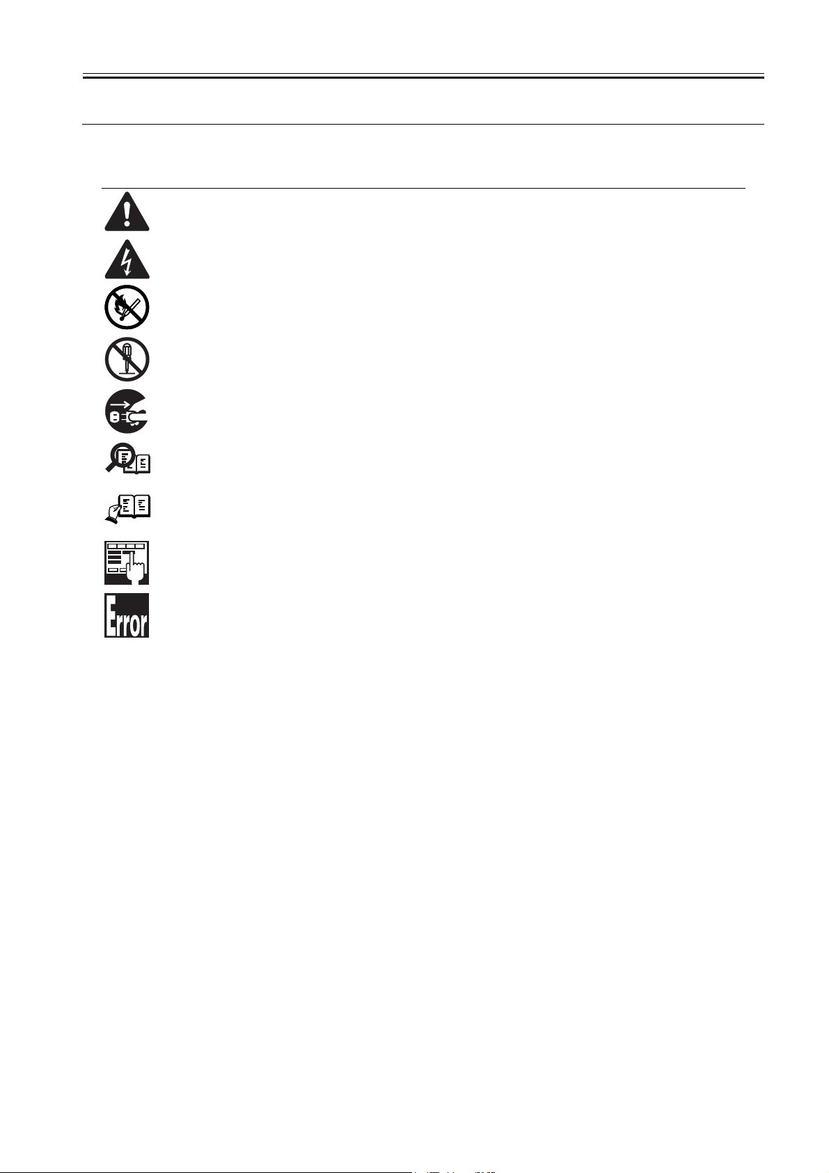
Symbols Used
This documentation uses the following symbols to indicate special information:
Symbol Description
Indicates an item of a non-specific nature, possibly classified as Note, Caution, or Warning.
Indicates an item requiring care to avoid electric shocks.
Indicates an item requiring care to avoid combustion (fire).
Indicates an item prohibiting disassembly to avoid electric shocks or problems.
Indicates an item requiring disconnection of the power plug from the electric outlet.
Indicates an item intended to provide notes assisting the understanding of the topic in question.
Memo
Introduction
REF.
Indicates an item of reference assisting the understanding of the topic in question.
Provides a description of a service mode.
Provides a description of the nature of an error indication.
Page 5

Introduction
The following rules apply throughout this Service Manual:
1. Each chapter contains sections explaining the purpose of specific functions and the relationship between electrical and mechanical systems with reference to the timing of operation.
In the diagrams, represents the path of mechanical drive; where a signal name accompanies the symbol , the arrow indicates the
direction of the electric signal.
The expression "turn on the power" means flipping on the power switch, closing the front door, and closing the delivery unit door, which results in
supplying the machine with power.
2. In the digital circuits, '1'is used to indicate that the voltage level of a given signal is "High", while '0' is used to indicate "Low".(The voltage value, however, differs from circuit to circuit.) In addition, the asterisk (*) as in "DRMD*" indicates that the DRMD signal goes on when '0'.
In practically all cases, the internal mechanisms of a microprocessor cannot be checked in the field. Therefore, the operations of the microprocessors
used in the machines are not discussed: they are explained in terms of from sensors to the input of the DC controller PCB and from the output of the
DC controller PCB to the loads.
The descriptions in this Service Manual are subject to change without notice for product improvement or other purposes, and major changes will be communicated in the form of Service Information bulletins.
All service persons are expected to have a good understanding of the contents of this Service Manual and all relevant Service Information bulletins and be
able to identify and isolate faults in the machine."
Page 6

Page 7

Contents
Contents
Chapter 1 Specifications
1.1 Specifications ............................................................................................................................................. 1- 1
1.1.1 UFR II Printer Driver ................................................................................................................................................1- 1
Chapter 2 Functions
2.1 Basic Function ............................................................................................................................................ 2- 1
2.1.1 Canon Driver Information Assist Service (DIAS) .....................................................................................................2- 1
2.1.2 FTP Printing.............................................................................................................................................................2- 1
2.1.3 Secured Print Jobs ..................................................................................................................................................2- 2
2.1.4 Up to 50 mm of Gutter .............................................................................................................................................2- 4
2.1.5 Processing on System.............................................................................................................................................2- 4
2.1.6 Sleep Processing.....................................................................................................................................................2- 5
2.1.7 Print Pause ..............................................................................................................................................................2- 5
2.1.8 Format Settings ....................................................................................................................................................... 2- 5
2.1.9 Staple & Group ........................................................................................................................................................2- 6
2.2 Changed Function ...................................................................................................................................... 2- 6
2.2.1 Application Color Matching Priority..........................................................................................................................2- 6
2.2.2 Custom Paper Size Settings Unit(Millimeter-Inch) ..................................................................................................2- 7
2.3 New Function.............................................................................................................................................. 2- 7
2.3.1 Use Skip Blank Pages Mode ...................................................................................................................................2- 7
Chapter 3 Installation
3.1 Checking Components ............................................................................................................................... 3- 1
3.1.1 Checking the Contents ............................................................................................................................................3- 1
3.2 Installation Procedure................................................................................................................................. 3- 1
3.2.1 Installation ...............................................................................................................................................................3- 1
3.2.2 Installing the Software .............................................................................................................................................3- 4
Page 8

Contents
Page 9

Chapter 1 Specifications
Page 10

Page 11

Contents
Contents
1.1 Specifications .................................................................................................................................................................1-1
1.1.1 UFR II Printer Driver ................................................................................................................................................................... 1-1
Page 12

Page 13

1.1 Specifications
Chapter 1
1.1.1 UFR II Printer Driver
Supported operating systems
Windows 2000 Professional/Server/Advanced Server
Windows XP Home Edition/Professional Edition(32 bit)
Microsoft Windows XP Professional x64 Edition (64 bit)
Microsoft Windows Server 2003 (32 bit)
Microsoft Windows Server 2003 x64 Edition (64 bit)
Mac OS X v10.2.8-V10.4.2
Font Handling:
Device fonts are not used as the printing uses the UFR II driver.
GDI raster fonts cannot be used - e.g.,
One Byte - Courier, MS Sans Serif, and MS Serif.
Two Byte - FixedSys, System, Small Fonts, Terminal
GDI vector fonts can be used - e.g.,
One Byte - Modern, Roman, and Script.
TureType fonts can be used - e.g.,
One Byte - Arial, Courier New, Symbol, Times New Roman
Note.
Each font becomes usable by the font addition to Windows.
Paper Size:
Paper Name Paper Size (mm)
A3 297.0 420.0
A4 210.0 297.0
A5 148.5 210.0
B4 257.0 364.0
B5 182.0 257.0
11 x 17 279.4 431.8
LEGAL 215.9 355.6
LETTER 215.9 279.4
EXECUTIVE 184.2 266.7
12 x 18 304.8 457.2
SRA3 320.0 450.0
13x19 330.2 482.6
Custom Paper Size Minimum 100.0 x 148.0
Custom Paper Size Maximum 313.0 x 474.0
Non-default paper:
Effective print area(mm) End of Paper(mm)
Main scaning Sub scaning Main scaning Sub scaning
SRA3(320 x 450) 300.00 430.00 10.00 10.00
12 x 18(305 x 457) 284.80 437.20 10.00 10.00
13 x 19(330 x 482) 305.00 457.40 12.60 12.60
0mm mode
Custom Size
Minimum
Custom Size
Maximum
SRA3(320 x 450)
12 x 18(305 x 457)
13 x 19(330 x 482)
Custom Size
Minimum
Custom Size
Maximum
0mm Mode
Main scaning Sub scaning Main scaning Sub scaning
314.50 444.00 2.75
300.00 451.00 2.50
314.20 466.50 7.75
95.00 142.00 2.50
314.50 466.50 7.75
90.00 138.00 5.00 5.00
303.00 464.00 5.00 5.00
Effective print area(mm) End of Paper(mm)
T-1-1
T-1-2
Width length
T-1-3
T-1-4
Top:4.00
Bottom:2.00
Top:4.00
Bottom:2.00
Top:4.00
Bottom:12.10
Top:4.00
Bottom:2.00
Top:4.00
Bottom:12.50
0011-6518
1-1
Page 14

Chapter 1
F-1-1
F-1-2
Area-Specific Paper Sizes:
In addition to default paper sizes (A4/LTR) and user-defined paper sizes, the printer driver supports area-specific paper sizes (e.g., Officio), and it handles these
area-specific paper sizes as user-defined paper sizes, requiring the user to register them in advance of use. To do so, see the instructions on registering user-defined
paper sizes for individual operating systems.
When an area-specific paper size is manually set up under [Form to Tray Assignment] of the driver UI, or if the size obtained by running dynamic configuration
happens to be an area-specific paper size, the driver operates in the corresponding mode. After performing all associated internal operations, the driver runs a check
of area-specific paper sizes stored as user defined paper sizes, and handles any matching paper as a default paper size (special paper ID) instead of as a user-defined
paper size. Moreover, the driver permits registration of multiple area-specific paper sizes, treating them as a separate paper group. The driver UI handles them using
specifications designed for LTR paper, permitting the use of finisher functions, which were previously offered for user-defined paper sizes (except the use of the
1-2
Page 15

Chapter 1
middle binding function). Although it will permit all settings, the printer unit may ignore some of the settings. (The printer driver will simply ignore them, not
issuing conflicts.)
Paper size Dimensions(mm)
Oficio OFI 216 317
Ecuadorian Oficio E_OFI 220 320
Bolivia Oficio B_OFI 216 355
Mexican Oficio M_OFI 216 341
Argentina Oficio A_OFI 220 340
Folio FOLIO 210 330
Argentina Letter A_LTR 220 280
Govermment Letter G_LTR 203 267
Govermment Legal G_LGL 203 330
Australian Foolscap A_FLSP 206 337
Foolscap FLSP 216 330
T-1-5
Width Height
Supported Paper Types:
T-1-6
Paper Type Paper Size
PLAIN
COLOR
RECYCLED
HEAVY
LABELS A3,B4,A4,LTR
Tracing Paper A3,A4/A4R,LTR
OHP
Tab Paper
3-hole Punch
A3,B4,A4/A4R,B5/B5R,A5R, 11x17, LGL, .LTR/LTRR, SRA3, 12 x 18, 13 x 19 EXEC, Oficio, User-defined paper
A4/,LTR
Finishing:
T-1-7
Finisher Rotate Shift Staple Punch Saddle
None OK N/A N/A N/A N/A
Shift Tray N/A OK N/A N/A N/A
Finisher-R1 N/A OK OK OK*1 N/A
Saddle Finisher-R2 N/A OK OK OK*1 OK
*1 N/A : not available. Puncher Unit is required for Punch hole.
1-3
Page 16

Page 17

Chapter 2 Functions
Page 18

Page 19

Contents
Contents
2.1 Basic Function................................................................................................................................................................2-1
2.1.1 Canon Driver Information Assist Service (DIAS) ....................................................................................................................... 2-1
2.1.2 FTP Printing................................................................................................................................................................................. 2-1
2.1.3 Secured Print Jobs ........................................................................................................................................................................ 2-2
2.1.4 Up to 50 mm of Gutter................................................................................................................................................................. 2-4
2.1.5 Processing on System .................................................................................................................................................................. 2-4
2.1.6 Sleep Processing .......................................................................................................................................................................... 2-5
2.1.7 Print Pause ................................................................................................................................................................................... 2-5
2.1.8 Format Settings ............................................................................................................................................................................ 2-5
2.1.9 Staple & Group ............................................................................................................................................................................ 2-6
2.2 Changed Function ..........................................................................................................................................................2-6
2.2.1 Application Color Matching Priority ........................................................................................................................................... 2-6
2.2.2 Custom Paper Size Settings Unit(Millimeter-Inch)..................................................................................................................... 2-7
2.3 New Function.................................................................................................................................................................2-7
2.3.1 Use Skip Blank Pages Mode ........................................................................................................................................................ 2-7
Page 20

Page 21

2.1 Basic Function
Chapter 2
2.1.1 Canon Driver Information Assist Service (DIAS)
This is a subset version of the Netspot Suite Service, supporting Driver only: we have selected Driver's functions (mainly, the functions to acquire Device configuration information) and redesigned them. The DIAS has the following functions:
- To acquire Device configuration information (acquisition when setting up Printer Property.)
0010-2995
- To make recognition in department-control printing (communication when setting up Printer Property or when making a department-control print)
Main structure of DIAS
DIAS (DLL): It is a module loaded on Driver
DIAS (Service): It does a service of installation on printer server when using a shared printer (resident process)
CBT: It is a module group to control a local port, such as Centronics Cable or USB
H-VDC: It is a module group which are needed for the driver function in DIAS.
Characteristics of DIAS
- Local printer can acquire the configuration information in DIAS (DLL) only.
Local printer means a printer that is "Peer to Peer" connected with Local PC via LPR/IPP/Centronics Cable/USB and that Spooler (Print queue) appears on the
Local PC.
- Shared printer needs to have DIAS (Service) installed on printer server.
The installation of DIAS (Service) must be done via Driver installer.
Shared printer means a printer whose Spooler (Print queue) appears on the printer server (Remote PC).
- However, in some cases, DIAS (Service) needs to be installed for Local Port connection. (See "Help" > "Troubleshoot the acquisition of configuration information".
1, WinNT4.0 OS Family (All)/ At the time of Local Port connection (LPT)
2, Win2k Server OS Family (Except Professional)/At the time of Local Port connection (LPT/USB) and Terminal Service introduction
3, WinXP Home/Professional Edition/ServerOS 2003 Family (X86:All)/ At the time of Local Port connection (LPT/USB) and Terminal Service introduction
About the version indication
The same Driver version indication as the one via Netspot Suite Service appears only when communicating with Device via DIAS (Service) (i.e., when connected
through a shared printer).
Compatibility of DIAS and Netspot Suite Service
DIAS and Netspot Suite Service are compatible and independent. Driver supporting DIAS does not use Netspot Suite Service even if it is installed.
Cautions when using DIAS
CBT controls all access to Local Port; both DIAS (DLL/Service) and NetSpot Suite Service use CBT to access Local Port from the same PC.
CBT was installed only on Netspot Suite Service before; it is automatically uninstalled in response to uninstalling the existing NetSpot Suite Service. Follow the
procedures below when uninstalling the former versions of NetSpot Suite Service v3.40 and when uninstalling JobMonitor v4.20 and former.
- Reinstall DIAS after the uninstallation is complete. (Reinstallation of DIAS is enabled via Installer.)
- Update NetSpot Suite Service to the latest version (v3.40 and later).
Former versions of NetSpot Suite Service v3.40
PS Printer Driver v2.10 and former
PCL5e Printer Driver v6.11 and former
PCL5c Printer Driver v6.11 and former
PCL6 Printer Driver v6.11 and former
UFR Printer Driver v1.10 and former
JobMonitor v4.10 and former
About a file name of the CBT module
Following files are installed in the 'c:\Windows\system' folder. (For Windows XP/Windows 2000/NT/Server2003, this folder name is to be '%SystemRoot%\system32'.)
AuPort.exe
NBCBTNT.dll / NBCBT95.dll
NBPORTNT.exe / NBPORT95.exe
NBLOCALT.dll
nbcbtspt.dat
Method of confirming when CBT is deleted
The following message is displayed.
"Failed to obtain device information Make sure no printer error occurred and printout port setting is correct."
2.1.2 FTP Printing
This device provides a FTP server for receiving print data. The device can accept print jobs sent in FTP from client PCs. This is called FTP printing, a new feature
first employed on iRC 6800. To use this feature, the FTP Print option must be selected. It is selected by default. You can access the option by pressing Ad Func,
System Settings, Network Settings, TCP/IP Settings, and FTP Print Settings buttons. In FTP Print Settings screen, only one pair of a user name and password can
be entered for the user who can log in to the FTP server. No settings are made for both of the fields by default.
0010-2996
2-1
Page 22

Chapter 2
F-2-1
Commands
The FTP server complies with the RFC 959 -- File Transfer Protocol -- but provides only printing function. Thus the server does not support other functions required
as a RFC 959 compliant server. The commands available for the FTP client are "user," "password," "bin," "put," "bye," "hash," and "help." There is no use of other
commands since the server does not provide functions other than printing. The following lists the notes to use the commands.
- To send print data with the command "put," set the mode to the binary mode using the command "bin." In the ascii mode, the data cannot be sent with the command
"put."
- If the user and password fields are blank, any user with any password can log in. If the user name "anonymous" is used, any character string can be entered as the
password. The device displays the string in User filed of Log screen.
- This function is featured mainly to print prn files output from PDL drivers. The device processes text files and the like as it receives data in LPR (and does not
properly print depending on settings.) The device of PostScript-compatible model can print PDF files, compatible with PDF V1.3.
The following shows a command specification example, which you will connect the device of the IP address "172.16.181.131" in FTP with the user name "test"
and the password "test" and print the file "test.prn" in the root directory of the drive C on the client PC.
C:\>ftp 172.16.181.131
Connected to 172.16.181.131.
220 Connection established.
User (172.16.181.131:(none)): test
331 Password required to login.
Password: Note: The password is not displayed.
230 User test logged in.
ftp> bin
200 Type set to IMAGE (binary).
ftp> put c:\test.prn
200 PORT command successful.
150 Opened BINARY data connection for file transfe
226 Transfer complete.
ftp: 15871 bytes sent in 0.00Seconds 15871000.00Kb
ftp> bye
221 Server closing down connection.
C:\>
Number of Connections and Used Ports
The maximum number of concurrent connections is three. If a user attempts to connect to the FTP server with which three connections have been established, the
user cannot log in and fails in connection. The default port for the FTP server is 21. There is no measure provided to change the port.
The control port time-out is set to 300 seconds. You need to re-connect to the server if you have left the connection for 300 seconds or more after logging in. The
data port time-out is 60 minutes. If a data transmission takes more than 60 minutes, the connection is automatically disconnected.
2.1.3 Secured Print Jobs
Overview:
Secured Print is the function that a password is provided to the PDL(UFR II and PCL, PS) print job and it is sent to the device. Then, it is rasterized on the device
side, saved in the image server and output by entering the password from the device's panel. This function is used when dealing with the documents which you do
0010-2997
not want other people to see, such as confidential documents.
a) Password is provided.
In order to conduct the Secured Print, the printer driver requires the user to enter the password from GUI. This password is provided to the print job and it is sent
to the device. This function can be conducted by using CPCA protocol(UFR II and PCL, PS).
b) Job execution and pending
PDL print job sent to the device as the Secured Print job is compiled on the job queue like the normal PDL print job. Then, it is rasterized by PDL interpreter, saved
in the image server as the document image file and becomes pending here. However, all job information, such as paper supply/output, the number of copies and
finishing information remains.
2-2
Page 23

Chapter 2
c) Job started by entering the password
If the Secured Print job is pending, the display indicating the pending state appears on the job status screen of the panel. If you select this job from the panel, you
are required to enter the password. When the password you entered is same as the password provided from the printer driver, the pending job will be started. When
the password is different, the job is treated as an error, so it is not started and it remains in the pending state. Entering the password to start the job cannot be executed
before the Secured Print job transfers to the pending state.
d) Output
The started Secured Print job is output to the printer engine with the top priority. This top priority means that if the jobs can be changed in priority order, the Secured
Print job can be prioritized. This job is proceeded according to all job information specified by the printer driver, etc., such as paper supply/output, the number of
copies and finishing information. When the processing is completed and all documents are output, the documents and job information stored in the image server
are deleted.
e) Operations for Secured Print jobs
Like other print jobs, Secured Print jobs can be deleted, interrupted, restarted and promoted by operating from the status screen of the print job. Regarding these
operations, the device side does not distinguish from operations of the normal PDL job. That is, the password entry is required only when the job is output. If you
interrupt or restart the job during outputting, the password setting and matching are not conducted.
f) Automatically delete of Secured Print Jobs
When Secured Print Job is continuing being suspended for a long time, apparatus deletes a job automatically.
There are options for automatic job deletion time -- 1, 2, 3, 6, 12, and 24 hours. With a view of security and memory usage, no option longer than 1 day is available.
The elapsed time starts after all the processes for the PDL data and the rendering for all the image data, for which Secured Print is specified, are finished.
g) Specifications and Limitations on Secured Print Jobs
The limitations on Secured Print jobs are listed as follows.
- Once data of a Secured Print job is printed, it is immediately deleted and cannot be printed any more.
- If the power for the controller is shut down, unprinted data of a Secured Print job is deleted from the printer.
- All the job information, represented by the paper source and output information, information of the number of copies, and finishing information, cannot be changed
on the printer.
- If the entire raster information for a Secured Print job cannot be stored in the image server (hard disk drive) due to insufficient memory, the job results in an error,
to be deleted.
- Up to 50 Secured Print jobs of image data being rendered and left unprinted can be stored.
F-2-2
F-2-3
2-3
Page 24

Chapter 2
F-2-4
F-2-5
2.1.4 Up to 50 mm of Gutter
Up to 50 mm of the gutter can be specified. The gutter can be adjusted within a range from 0 mm to 50 mm in 1 mm increments. The local UI and the print driver
have the controls for the gutter settings.
The image is shifted to the width value specified for gutter, making a margin. If the shift causes the image to overflow from the printable area, the overflowing area
is missing from the print results. The overflowing image will not be reduced to fit into the printable area.
F-2-6
0010-2998
F-2-7
The gutter width range changed to 0-50 mm.
US: 0.0 to 2.0 inches
UK: 0.0 to 50.0 mm
2.1.5 Processing on System
Processing after Power Shutdown
2-4
0010-3000
Page 25

Chapter 2
If the power is shut down during PDL data processing, all the image data temporarily stored in the hard disk drive to be printed or stored in Mail Boxes are destroyed
and the jobs are canceled. PDL data stored in the hard disk drive immediately before a power shutdown are destroyed as the power is shut down. Processing the
data of those, therefore, will not resume when the power is turned on after the shutdown. Jobs interrupted by a power shutdown will be displayed in the Log list
with the End Code "NG (#852)."
2.1.6 Sleep Processing
Sleep Processing
The 1 W power consumption mode is employed as Sleep 3 in the printers that supports the UFR II. Of network interrupts, whereas a traditional printer restores
when receiving packets addressed to it, new printer restores when receiving either of the following packets.
- ARP packets
- Packets addressed to the printer
- Broadcast packets for SNMP search with specific patterns
- SLP multicast packets with specific patterns
0010-3001
- CPCA echo (broadcast) packets with specific patterns
2.1.7 Print Pause
You can suspend ongoing printing of all jobs from the control panel. Likewise, you can resume the printing working from the control panel. There will be no suspension of data input for the network or PDL processing. To enable Print Pause, use the following service mode:
COPIER>OPTION>USER>PR-PSESW
0: disable (do not indicate)
1: enable (indicate)
0011-6497
(default: '0')
F-2-8
2.1.8 Format Settings
A function to enable the selection of the following will be added in regard to the text used to print the result of a job and the following notations to the lead or trail
edge: Print Date, Print User Name, Print Page Number:
Font
Style
Size
0011-6498
Color
A change made to Format Settings will affect the following in common, and individual selection will not be possible: Print Date, Print User Name, Print Page
Number.
F-2-9
2-5
Page 26

Chapter 2
F-2-10
F-2-11
2.1.9 Staple & Group
You can use it to enable the selection of stapling when printing in Group mode. Staple & Group permits stapling of pages in sets.
F-2-12
If 'Store' is selected as 'Output Method' on the Finishing tab, [Staple & Group] will be grayed out, not permitting selection.
If 'Store' is selected as 'Output Method' while selecting [Staple & Group], a switchover will take place for [Finishing] so that [Staple & Group] will be [Collate].
0011-6499
2.2 Changed Function
2.2.1 Application Color Matching Priority
There have been some cases that color reproducibility may become inappropriate if users perform color matching in the printer driver again though they have already
done it in PC.
When the checkbox for Application Color Matching Priority under [ In Quality > Manual Grayscale Settings > Grayscale Settings > Matching] is cleared, it can
declare to the application software on PC that Driver handles ICM processing.
This notice enables to perform Image Color Matching processing as designated in printer driver UI since the process is not done to the color values given from OS
to driver.
Though Application Color Matching Priority is set to on as default so that existing version can be compatible, when specified color tinge cannot be materialized,
clearing the checkbox makes it manageable.
Applicable OS: Windows2000, Windows XP, Windows 2003 Server
0011-6531
2-6
Page 27

F-2-13
Chapter 2
2.2.2 Custom Paper Size Settings Unit(Millimeter-Inch)
In the past, paper size was displayed in millimeter or inch depending on the destinations concerning the custom paper size settings. This printer driver enables users
to select the unit (Millimeter or Inch).
F-2-14
0011-6534
2.3 New Function
2.3.1 Use Skip Blank Pages Mode
If [Use Skip Blank Pages Mode] is set to [On], blank pages are skipped even if [2-sided Printing] is set in [Print Style].
For instance, when the first page is blank and the second and third pages have data, the first page is skipped, the data of second page is printed on the front side of
the sheet, and that of third page is printed on the back side of the same sheet.
Similarly, when the first page has data, the second is blank and the third has data, the data of first page is printed on the front side of the sheet, the second page is
skipped, and the data of third page is printed on the back side of the same sheet.
Though the setting of [Skip Blank Pages] is conducted on the control panel of the iR main body, a printer driver released this time enables users to specify the setting
in the driver.
[Finishing] - [Finishing Details]
0011-6541
2-7
Page 28

Chapter 2
F-2-15
2-8
Page 29

Chapter 3 Installation
Page 30

Page 31

Contents
Contents
3.1 Checking Components ...................................................................................................................................................3-1
3.1.1 Checking the Contents ................................................................................................................................................................. 3-1
3.2 Installation Procedure ....................................................................................................................................................3-1
3.2.1 Installation.................................................................................................................................................................................... 3-1
3.2.2 Installing the Software ................................................................................................................................................................. 3-4
Page 32

Page 33

3.1 Checking Components
Chapter 3
3.1.1 Checking the Contents
[1]
[5]
[8]
[2]
[6]
F-3-1
[3]
0011-1206
[4]
[7]
[9]
[1] BOOT ROM 1 pc.
[2] LIPS LX User Software CD-ROM 1 pc.
[3] BDL Software Guide 1 pc.
[4] BM-LinkS (UFRII Printer Kit-L1) 1 pc.
[5] Color Network ScanGear CD-ROM 1 pc.
[6] Net worlk Scan Gear UsersGuide 1 pc.
[7] BDL Software Guide 1 pc.
[8] Net worlk Scan Gear UsersGuide 1 pc.
[9] BM-LinkS (LIPS LXPrinter & Scaner Kit-L1) 1 pc.
3.2 Installation Procedure
3.2.1 Installation
1. Turning Off the iR Machine
Turning Off the Main Power
To protect the hard disk against damage, be sure to go through the following steps in sequence when turning off the main power:
1. Hold down the control panel power switch for 3 sec or more.
2. Follow the instructions for the shut-down sequence shown on the screen so that the machine's main power switch may be turned off.
3. Turn off the main power switch.
4. Disconnect the power cable (from the power outlet).
2. Installation Procedure
1) Disconnect the connector and the cable.
- reader communications cable connector [1] (2 locations)
- DADF cable [2] (1 location)
0011-1211
3-1
Page 34

Chapter 3
2) Remove the rear right cover.
- 7 screws [1].
[2]
[1]
F-3-2
[2]
[1]
3) Remove the controller box cover [2].
- 16 screws [1]
[2]
[2]
F-3-3
[2]
[2]
[1]
4) Push the lock lever [1] to remove the boot ROM [2].
3-2
[2]
F-3-4
Page 35

5) Fit the included boot ROM [1] in place.
[1]
[2]
[1]
Chapter 3
F-3-5
F-3-6
6) Connect the cables and put back the cover disconnected and removed in steps 2) and 3), respectively.
7) Turn on the main power switch.
8) When a message has appeared prompting you to turn off and then on the power, perform the shut-down sequence to turn off the main power switch, and then
turn it back on.
3. Checking the Connection
Go through the following to make sure the machine correctly recognizes the presence of the boot ROM:
1) Check the Check Counter key [1] on the control panel.
1
2
3
5
6
4
8 9
7
0
1 2 3
[1]
F-3-7
2) Press the Check Device Configuration key [1].
3-3
Page 36

Chapter 3
[1]
F-3-8
3) Check to see that'UFR II Printer KIt-L1' are indicated as accessories.
3.2.2 Installing the Software
1. Network Setting
MEMO:
Check that the network setting of the host machine is completed.
1) Press the User Mode button.
2) Press [System Additional Functions Settings].
3) Press [Network Settings].
4) Set the confirmation display for the change settings /Display connection confirm.
5) Make <TCP/IP Settings>.
MEMO:
For more information, see "Network Guide" in the Users' Manual.
2. PC Print Confirmation Procedure (reference information)
- After installing the printer driver to a PC running Windows 2000/XP/Server2003, you can make a print from the PC to the iR host machine.
- You can check whether or not print from a PC is conducted properly by executing the test page print of the printer driver.
- To install the printer driver,
Set the LIPS LX user software CD on the CD-ROM drive and follow the procedure which is automatically activated. If the procedure is not automatically
activated, double-click Setup.exe in the CD-ROM.
For more information, see Readme.txt in the CD-ROM.
- Use the IP address that you can obtain from User Mode> System Additional Functions Settings > Network Settings> TCP/IP Settings> IP Address Settings on
the control panel o If an IP address of the iR host machine is set,
f the iR machine as a port setting of the printer driver.
e.g.: Select LIPSLX PrinterDriver Setup Wizard> Printer Information Setup> Port Setup> Add Port and press Setup button. Select Standard TCP/IP Port, and
when the window to add a standard TCP/IP printer port appears, enter the obtained IP address of the iR host machine to the IP address.
To print the test page,
After installation of the printer driver is completed, restart the PC if necessary, and then select the added printer from Start> Setup> Printer. Right-click the
mouse to indicate the menu, and then open Property. Press the test page button in General Settings tab.
MEMO:
For information on connection with a PC, see "Network Guide" in the Users' Manual.
For information on installation of the driver, see "Software Guide" in the Users' Manual.
3. Installation of ScanGear
- Install ScanGear Software from Color Network ScanGear CD-ROM to read originals from the reader to the PC.
MEMO:
Verify that [Remote Scanner] is indicated on the control panel of the host machine.
After this kit is installed, [Remote Scanner] is indicated on the control panel.
1) Execute Setup.
2) Following the instructions given in the window, input the IP address, etc., of the host machine.
3) Start up ScanGear and check if data can be read.
MEMO:
For more information, see "Color Network ScanGear" in the Users Manual.
0011-1213
- After installing this product, be sure to conduct "Auto Gradation Adjustment" of the host machine for color adjustments.
Additional Functions>Adjustment/Cleaning>Auto Gradation Adjustment>Full Adjust.
3-4
Page 37

Jan 25 2006
Page 38

 Loading...