

Canon iR5870C, iR5870Ci, iR6870C, iR6870Ci color ufr ii printer kit-l1 Installation Procedure
Page 1

Installation Procedure
Canon Color
Color UFRII Printer Kit-L1
Jan 25 2006
Page 2

Page 3

Application
This manual has been issued by Canon Inc. for qualified persons to learn technical theory, in-
stallation, maintenance, and repair of products. This manual covers all localities where the prod-
ucts are sold. For this reason, there may be information in this manual that does not apply to
your locality.
Corrections
This manual may contain technical inaccuracies or typographical errors due to improvements or
changes in products. When changes occur in applicable products or in the contents of this manual,
Canon will release technical information as the need arises. In the event of major changes in the
contents of this manual over a long or short period, Canon will issue a new edition of this manual.
The following paragraph does not apply to any countries where such provisions are inconsistent
with local law.
Trademarks
The product names and company names used in this manual are the registered trademarks of the
individual companies.
Copyright
This manual is copyrighted with all rights reserved. Under the copyright laws, this manual may
not be copied, reproduced or translated into another language, in whole or in part, without the
written consent of Canon Inc.
COPYRIGHT © 2001 CANON INC.
Printed in Japan
Caution
Use of this manual should be strictly supervised to avoid disclosure of confidential information.
Page 4
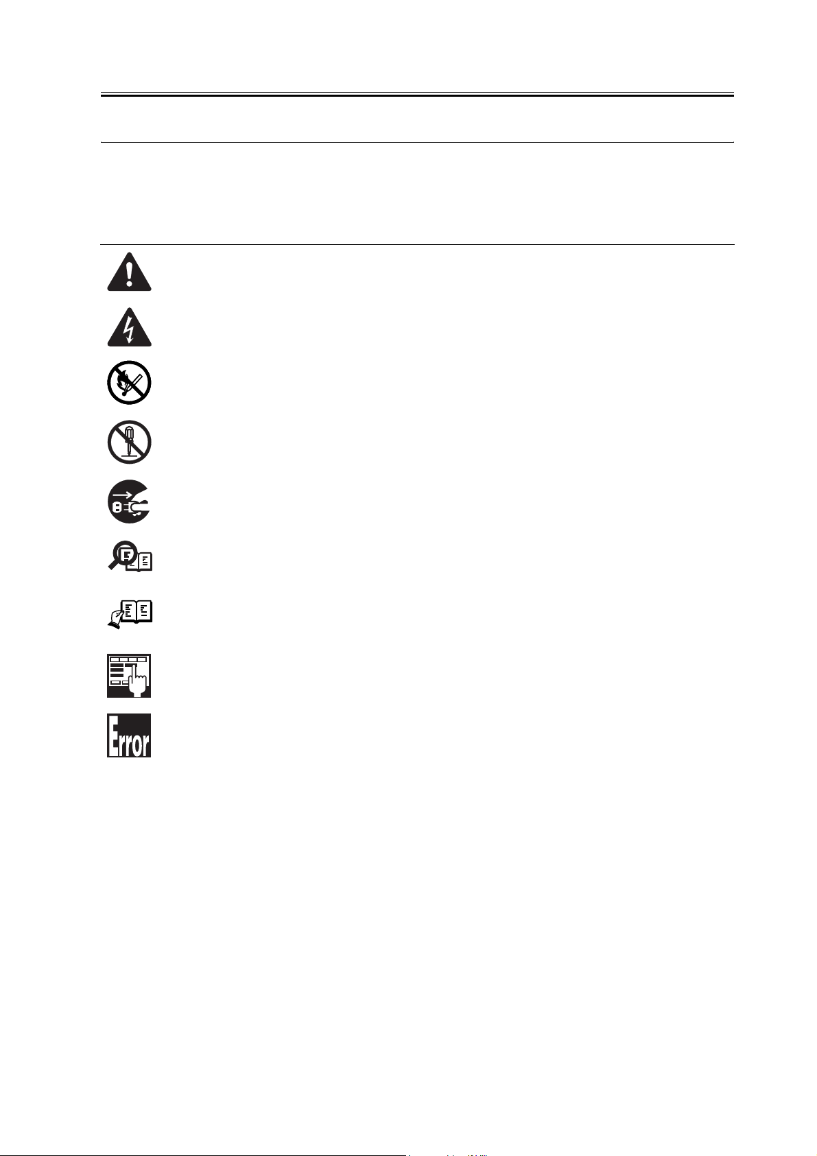
Symbols Used
This documentation uses the following symbols to indicate special information:
Symbol Description
Indicates an item of a non-specific nature, possibly classified as Note, Caution, or Warning.
Indicates an item requiring care to avoid electric shocks.
Indicates an item requiring care to avoid combustion (fire).
Indicates an item prohibiting disassembly to avoid electric shocks or problems.
Introduction
Memo
REF.
Indicates an item requiring disconnection of the power plug from the electric outlet.
Indicates an item intended to provide notes assisting the understanding of the topic in question.
Indicates an item of reference assisting the understanding of the topic in question.
Provides a description of a service mode.
Provides a description of the nature of an error indication.
Page 5

Introduction
The following rules apply throughout this Service Manual:
1. Each chapter contains sections explaining the purpose of specific functions and the relationship between electrical and mechanical systems with reference to the timing of operation.
In the diagrams, represents the path of mechanical drive; where a signal name accom-
panies the symbol , the arrow indicates the direction of the electric signal.
The expression "turn on the power" means flipping on the power switch, closing the front
door, and closing the delivery unit door, which results in supplying the machine with power.
2. In the digital circuits, '1'is used to indicate that the voltage level of a given signal
is "High", while '0' is used to indicate "Low".(The voltage value, however, differs from
circuit to circuit.) In addition, the asterisk (*) as in "DRMD*" indicates that the DRMD
signal goes on when '0'.
In practically all cases, the internal mechanisms of a microprocessor cannot be checked in
the field. Therefore, the operations of the microprocessors used in the machines are not
discussed: they are explained in terms of from sensors to the input of the DC controller PCB
and from the output of the DC controller PCB to the loads.
The descriptions in this Service Manual are subject to change without notice for product improvement or other purposes, and major changes will be communicated in the form of Service
Information bulletins.
All service persons are expected to have a good understanding of the contents of this Service
Manual and all relevant Service Information bulletins and be able to identify and isolate
faults in the machine."
Page 6

Page 7

Contents
Contents
Chapter 1 Installation Procedure
1.1 Checking components ....................................................................................................................................... 2
1.1.1Checking the Contents................................................................................................................................. 2
1.2 Installation procedure......................................................................................................................................... 3
1.2.1Installation ...................................................................................................................................................... 3
1.2.2Installing the Software.................................................................................................................................. 4
Page 8

Contents
Page 9

Chapter 1 Installation
Procedure
Page 10

Chapter 1
1.1 Checking components
1.1.1 Checking the Contents
[2]
[1]
[5]
[8]
[6]
F-1-1
[3]
0011-1206
[4]
[7]
[9]
[1] BOOT ROM 1 pc.
[2] LIPS LX User Software CD-ROM 1 pc.
[3] BDL Software Guide 1 pc.
[4] BM-LinkS (UFRII Printer Kit-L1) 1 pc.
[5] Color Network ScanGear CD-ROM 1 pc.
[6] Net worlk Scan Gear UsersGuide 1 pc.
[7] BDL Software Guide 1 pc.
[8] Net worlk Scan Gear UsersGuide 1 pc.
[9] BM-LinkS (LIPS LXPrinter & Scaner Kit-L1) 1 pc.
2
Page 11

Chapter 1
1.2 Installation procedure
1.2.1 Installation
1. Turning Off the iR Machine
Turning Off the Main Power
To protect the hard disk against damage, be sure to go
through the following steps in sequence when turning
off the main power:
1. Hold down the control panel power switch for 3 sec
or more.
2. Follow the instructions for the shut-down sequence
shown on the screen so that the machine's main
power switch may be turned off.
3. Turn off the main power switch.
4. Disconnect the power cable (from the power out-
let).
2. Installation Procedure
1) Disconnect the connector and the cable.
- reader communications cable connector [1] (2 lo-
cations)
- DADF cable [2] (1 location)
0011-1211
[2]
[1]
[2]
F-1-3
3) Remove the controller box cover [2].
- 16 screws [1]
[2]
[2]
[2]
[1]
F-1-2
2) Remove the rear right cover.
- 7 screws [1].
[2]
[1]
[2]
F-1-4
4) Push the lock lever [1] to remove the boot ROM
[2].
3
Page 12

Chapter 1
[1]
[2]
[1]
F-1-5
5) Fit the included boot ROM [1] in place.
Go through the following to make sure the machine
correctly recognizes the presence of the boot ROM:
1) Check the Check Counter key [1] on the control
panel.
1
2
3
5
6
4
8 9
7
0
1 2 3
[1]
F-1-7
2) Press the Check Device Configuration key [1].
F-1-6
6) Connect the cables and put back the cover discon-
nected and removed in steps 2) and 3), respectively.
7) Turn on the main power switch.
8) When a message has appeared prompting you to
turn off and then on the power, perform the shut-
down sequence to turn off the main power switch,
and then turn it back on.
3. Checking the Connection
[1]
F-1-8
3) Check to see that'UFR II Printer KIt-L1' are indicat-
ed as accessories.
1.2.2 Installing the Soft-
ware
1. Network Setting
MEMO:
Check that the network setting of the host machine is
completed.
1) Press the User Mode button.
2) Press [System Additional Functions Settings].
0011-1213
4
Page 13

Chapter 1
3) Press [Network Settings].
4) Set the confirmation display for the change settings
/Display connection confirm.
5) Make <TCP/IP Settings>.
MEMO:
For more information, see "Network Guide" in the Us-
ers' Manual.
2. PC Print Confirmation Procedure (reference in-
formation)
- After installing the printer driver to a PC running
Windows 2000/XP/Server2003, you can make a
print from the PC to the iR host machine.
- You can check whether or not print from a PC is
conducted properly by executing the test page print
of the printer driver.
- To install the printer driver,
Set the LIPS LX user software CD on the CD-ROM
drive and follow the procedure which is automati-
cally activated. If the procedure is not automatically
activated, double-click Setup.exe in the CD-ROM.
For more information, see Readme.txt in the CD-
ROM.
- Use the IP address that you can obtain from User
Mode> System Additional Functions Settings >
Network Settings> TCP/IP Settings> IP Address
Settings on the control panel o If an IP address of
the iR host machine is set,
f the iR machine as a port setting of the printer driv-
er.
After installation of the printer driver is completed,
restart the PC if necessary, and then select the add-
ed printer from Start> Setup> Printer. Right-click
the mouse to indicate the menu, and then open
Property. Press the test page button in General Set-
tings tab.
MEMO:
For information on connection with a PC, see "Net-
work Guide" in the Users' Manual.
For information on installation of the driver, see
"Software Guide" in the Users' Manual.
3. Installation of ScanGear
- Install ScanGear Software from Color Network
ScanGear CD-ROM to read originals from the
reader to the PC.
MEMO:
Verify that [Remote Scanner] is indicated on the con-
trol panel of the host machine.
After this kit is installed, [Remote Scanner] is indicat-
ed on the control panel.
1) Execute Setup.
2) Following the instructions given in the window, in-
put the IP address, etc., of the host machine.
3) Start up ScanGear and check if data can be read.
MEMO:
For more information, see "Color Network ScanGear"
in the Users Manual.
e.g.: Select LIPSLX PrinterDriver Setup Wizard>
Printer Information Setup> Port Setup> Add Port
and press Setup button. Select Standard TCP/IP
Port, and when the window to add a standard TCP/
IP printer port appears, enter the obtained IP ad-
dress of the iR host machine to the IP address.
To print the test page,
- After installing this product, be sure to conduct "Au-
to Gradation Adjustment" of the host machine for col-
or adjustments.
Additional Functions>Adjustment/Cleaning>Auto
Gradation Adjustment>Full Adjust.
5
Page 14

Page 15

Jan 25 2006
Page 16

 Loading...