

Page 1

Installation Procedure
iR C6800 Series
Jan 25 2006
Page 2

Page 3

Application
This manual has been issued by Canon Inc. for qualified persons to learn technical theory, in-
stallation, maintenance, and repair of products. This manual covers all localities where the prod-
ucts are sold. For this reason, there may be information in this manual that does not apply to
your locality.
Corrections
This manual may contain technical inaccuracies or typographical errors due to improvements or
changes in products. When changes occur in applicable products or in the contents of this manual,
Canon will release technical information as the need arises. In the event of major changes in the
contents of this manual over a long or short period, Canon will issue a new edition of this manual.
The following paragraph does not apply to any countries where such provisions are inconsistent
with local law.
Trademarks
The product names and company names used in this manual are the registered trademarks of the
individual companies.
Copyright
This manual is copyrighted with all rights reserved. Under the copyright laws, this manual may
not be copied, reproduced or translated into another language, in whole or in part, without the
written consent of Canon Inc.
COPYRIGHT © 2001 CANON INC.
Printed in Japan
Caution
Use of this manual should be strictly supervised to avoid disclosure of confidential information.
Page 4
Symbols Used
This documentation uses the following symbols to indicate special information:
Symbol Description
Indicates an item of a non-specific nature, possibly classified as Note, Caution, or Warning.
Indicates an item requiring care to avoid electric shocks.
Indicates an item requiring care to avoid combustion (fire).
Indicates an item prohibiting disassembly to avoid electric shocks or problems.
Introduction
Memo
REF.
Indicates an item requiring disconnection of the power plug from the electric outlet.
Indicates an item intended to provide notes assisting the understanding of the topic in question.
Indicates an item of reference assisting the understanding of the topic in question.
Provides a description of a service mode.
Provides a description of the nature of an error indication.
Page 5

Introduction
The following rules apply throughout this Service Manual:
1. Each chapter contains sections explaining the purpose of specific functions and the relationship between electrical and mechanical systems with reference to the timing of operation.
In the diagrams, represents the path of mechanical drive; where a signal name accom-
panies the symbol , the arrow indicates the direction of the electric signal.
The expression "turn on the power" means flipping on the power switch, closing the front
door, and closing the delivery unit door, which results in supplying the machine with power.
2. In the digital circuits, '1'is used to indicate that the voltage level of a given signal
is "High", while '0' is used to indicate "Low".(The voltage value, however, differs from
circuit to circuit.) In addition, the asterisk (*) as in "DRMD*" indicates that the DRMD
signal goes on when '0'.
In practically all cases, the internal mechanisms of a microprocessor cannot be checked in
the field. Therefore, the operations of the microprocessors used in the machines are not
discussed: they are explained in terms of from sensors to the input of the DC controller PCB
and from the output of the DC controller PCB to the loads.
The descriptions in this Service Manual are subject to change without notice for product improvement or other purposes, and major changes will be communicated in the form of Service
Information bulletins.
All service persons are expected to have a good understanding of the contents of this Service
Manual and all relevant Service Information bulletins and be able to identify and isolate
faults in the machine."
Page 6

Page 7

Contents
Contents
Chapter 1 Installation Procedure
1.1 Making Pre-Checks ............................................................................................................................................ 2
1.1.1Selecting the Site of Installation ................................................................................................................. 2
1.1.2Installation Environment .............................................................................................................................. 3
1.1.3Checking the Contents................................................................................................................................. 4
1.2 Unpacking and Installation................................................................................................................................ 8
1.2.1Before Starting the Work ............................................................................................................................. 8
1.2.2Turning Off the Host Machine..................................................................................................................... 8
1.2.3Unpacking the Machine ............................................................................................................................... 8
1.2.4Attaching the Pickup Assembly ................................................................................................................ 11
1.2.5Attaching the Scanner System ................................................................................................................. 12
1.2.6Locking the Primary Transfer Roller in Place......................................................................................... 13
1.2.7Before Attaching the Developing Assembly ........................................................................................... 13
1.2.8Attaching the Color Developing Assemblies .......................................................................................... 17
1.2.9Attaching the Black Developing Assembly ............................................................................................. 20
1.2.10Attaching the Process Unit...................................................................................................................... 23
1.2.11Attaching the Fixing Assembly ............................................................................................................... 27
1.2.12Fitting the Black Toner Bottle.................................................................................................................. 28
1.2.13Checking the Environment Switch ......................................................................................................... 29
1.2.14Turning On the Main Power Switch....................................................................................................... 29
1.2.15Setting Up the Paper Cassette............................................................................................................... 30
1.2.16Changing the Deck Paper Size (right, left) ........................................................................................... 31
1.2.17Fitting the Color Toner Cartridge............................................................................................................ 32
1.2.18Supplying Black Toner ............................................................................................................................. 33
1.2.19Cleaning the Intermediate Transfer Belt ............................................................................................... 33
1.2.20Supplying Color Toner ............................................................................................................................. 34
1.2.21Setting Auto Gradation Correction......................................................................................................... 34
1.2.22Checking the Image/Operation............................................................................................................... 35
1.2.23Adjusting the Horizontal Registration .................................................................................................... 35
1.2.24Adjusting the Leading Edge Registration.............................................................................................. 37
1.2.25Securing the Machine in Place............................................................................................................... 38
1.2.26If Not Connected to a Network ............................................................................................................... 39
1.2.27Affixing the Shut-down warning label .................................................................................................... 39
1.3 Checking the Connection to the Network ..................................................................................................... 40
1.3.1Overview ...................................................................................................................................................... 40
1.3.2Using the PING Utility ................................................................................................................................ 40
1.3.3Using a Remote Host Address ................................................................................................................. 40
1.4 Troubleshooting the Network.......................................................................................................................... 41
1.4.1Overview ...................................................................................................................................................... 41
1.4.2Checking the Connection of the Network Cable.................................................................................... 41
1.4.3Using a Loopback Address ....................................................................................................................... 41
1.4.4Using a Local Host Address...................................................................................................................... 41
1.5 Installing the Card Reader............................................................................................................................... 42
Page 8

Contents
1.5.1Points to Note About Installation ............................................................................................................. 42
1.5.2Checking the Contents.............................................................................................................................. 42
1.5.3Installation ................................................................................................................................................... 42
1.5.4Using the Card Reader in Combination with NetSpot Accountant (hereafter, NSA)....................... 44
1.6 Installing the NE Controller-A1....................................................................................................................... 45
1.6.1NE Controller-A1 Installation Procedure ................................................................................................ 45
1.7 Installing the Original Tray.............................................................................................................................. 46
1.7.1Checking the Contents.............................................................................................................................. 46
1.7.2Attachment.................................................................................................................................................. 46
1.8 Installing the Key Switch Unit-A1................................................................................................................... 47
1.8.1Checking the Contents.............................................................................................................................. 47
1.8.2Attachment.................................................................................................................................................. 47
1.9 Installing the Reader Heater Kit..................................................................................................................... 49
1.9.1Checking the ComponentsÅiReader Heate-C1Åj................................................................................. 49
1.9.2Before Starting the Work........................................................................................................................... 49
1.9.3Installation Procedure................................................................................................................................ 49
1.10 Installing the Voice Guidance Kit................................................................................................................. 53
1.10.1Checking Items in the Package ............................................................................................................. 53
1.10.2Turning Off the Host Machine................................................................................................................ 54
1.10.3Installation Procedure ............................................................................................................................. 54
Page 9

Chapter 1 Installation
Procedure
Page 10
Chapter 1
1.1 Making Pre-Checks
1.1.1 Selecting the Site of Installation
0002-6395
iR C6800C / iR C6800CN / iR 5800C / iR 5800CN / / iR 5870Ci / iR 5870C / iR 6870Ci / iR 6870C
Be sure that the site of installation satisfies the following requirements; if possible, visit the user's before delivery of
the machine:
(1) There must be a properly grounded power outlet that is rated as indicated (+/-10%) and that may be used ex-
clusively by the machine.
(2) The temperature of the site must be between 15 and 30 deg C and humidity, between 25% and 80%. The ma-
chine may not be installed near a water faucet, water boiler, humidifier, or refrigerator.
(3) The site must not be near a source of fire or in an area subject to dust or ammonium gas. If the area is exposed
to the direct rays of the sun, the windows must be furnished with curtains.
(4) The site must be well ventilated. However, the machine must not be installed near the air vent of the room. The
ozone generated by the machine while in operation is not of a level that can harm the health of the individuals
around the machine. Nevertheless, some may find it to be unpleasant, and the room must be ventilated often.
(5) The machine must be placed on a level floor so that all its feet remain in contact with the floor and the machine
will remain level.
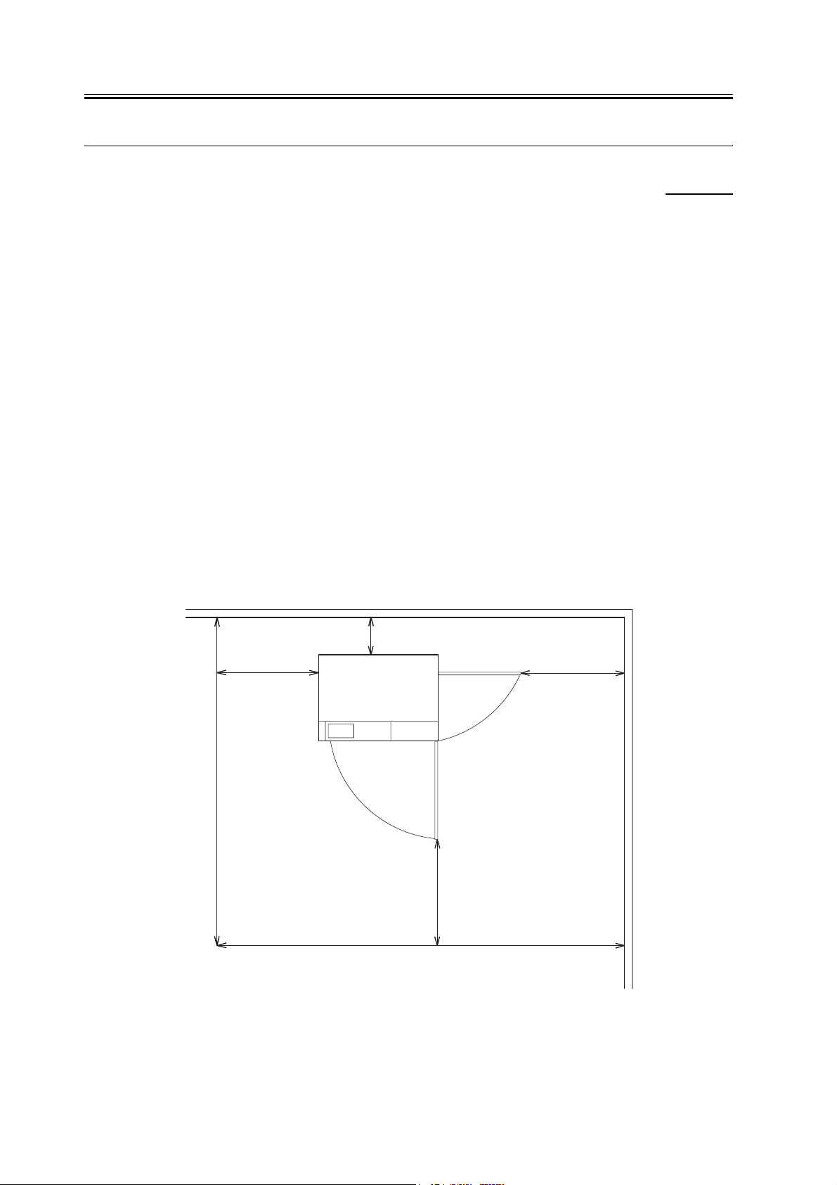
(6) There must be enough space around the machine. The following diagram shows the minimum dimensions;
whenever possible, be sure there will be more space than indicated:
(a) Copier [1]
200cm
50cm
10cm
[1]
210cm min
F-1-1
50cm
50cm
2
Page 11
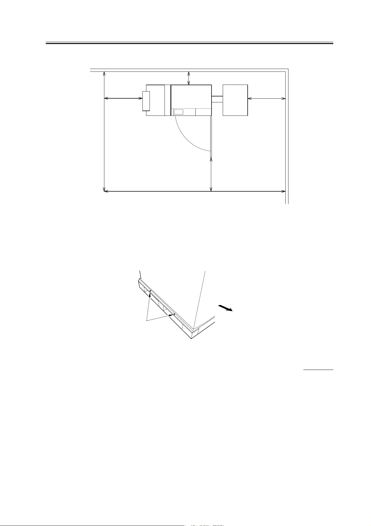
(b) Copier [1] + Punch Unit [2] + Finisher [3] + Side Deck [4]
10cm
Chapter 1
[4]
50cm
200cm
50cm
[3]
[2]
[1]
50cm
310cm
F-1-2
(7) The machine will be placed on the side of the slope plate having a pin hole [1]. Be sure that the space will be
on this side (left side).
The side of the slope plate having a pin hole (left) is where the delivery side of the machine will be, with the
front of the machine facing the side indicated by the arrow.
Front
[1]
F-1-3
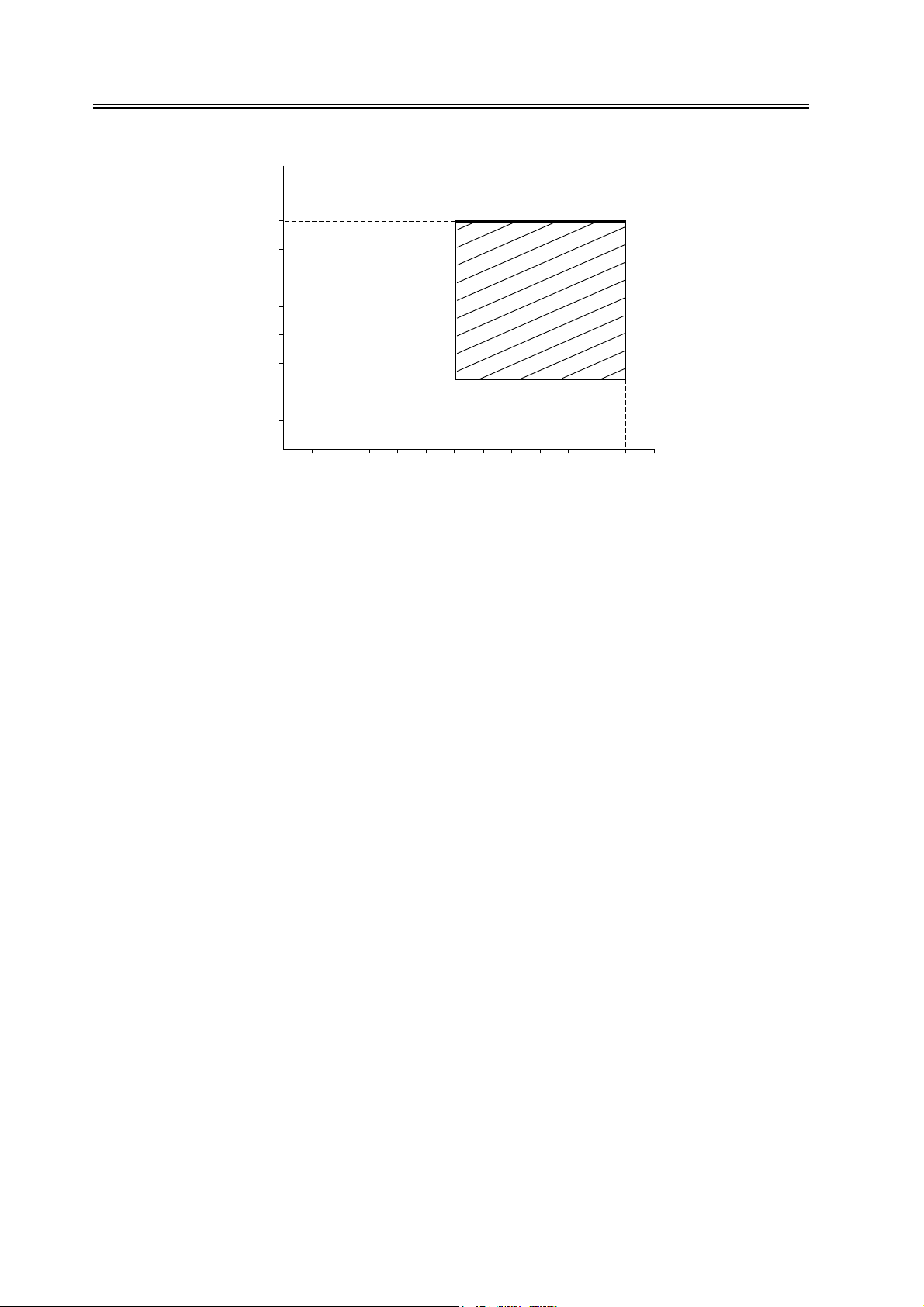
1.1.2 Installation Environment
iR C6800C / iR C6800CN / iR 5800C / iR 5800CN / / iR 5870Ci / iR 5870C / iR 6870Ci / iR 6870C
Check that the environment of the site meets the following requirements:
0002-6399
3
Page 12
Chapter 1
(%RH)
80
75
60
[1]
40
25
20
10
010152030˚C
(32) (50) (59) (68) (86) (˚F)
[2]
F-1-4
[1] Humidity
[2] Temperature
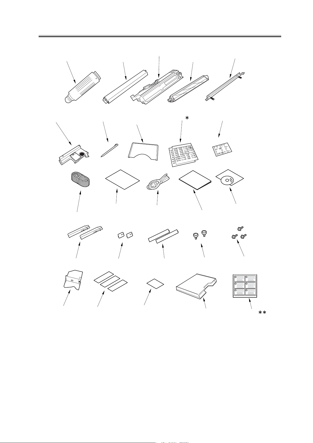
1.1.3 Checking the Contents
iR C6800C / iR C6800CN / iR 5800C / iR 5800CN / / iR 5870Ci / iR 5870C / iR 6870Ci / iR 6870C
0002-6404
4
Page 13
Chapter 1
[6]
[1]
[7]
[2]
[8]
[3]
[9]
[4]
[5]
[10]
[15]
[21]
[11]
[16]
[22]
[12]
[17]
[23]
[13]
[18]
[14]
[19] [20]
[24]
F-1-5
[1] Black toner bottle (black; only for 100/230V AU model) 1 pc.
[2] Color toner cartridge(cyan, magenta, yellow;
only for 100V/230V AU model)
1 pc. each
[25]
[3] Black developing assembly (black) 1 pc.
[4] Color developing assembly (cyan, magenta, yellow) 1 pc. each
5
Page 14

Chapter 1
[5] Black developing assembly locking plate 1 pc.
[6] Process unit cover 1 pc.
[7] Touch pen 1 pc.
[8] Service book case 1 pc.
[9]* Cassette size label* 2 pc.
[10] ADF size label 1 pc.
[11] Grounding cord (100-V model only) 1 pc.
[12] QR sheet (100-V model only) 1 pc.
[13] Power cord (230-V model only) 1 pc.
[14] Service book 1 pc.
[15] User's Manual 1
[16] Grip 2 pc.
[17] Pickup assembly face place 2 pc.
[18] Delivery assembly face plate 2 pc.
[19] Binding screw (M4X8) 2 pc.
[20] RS tightening screw (M4X8) 3 pc.
[21] Left deck locking plate 1 pc.
[22] No Copy label (non-100-V model) 3 pc.
[23] Glass Cleaning instructions label (non-100-V model) 1 pc.
[24] Glass Cleaning instructions label (non-100-V model) 1 pc.
[25]** Shut-down warning label 1 pc.
* Found inside the cassette 3 (upper cassette).
** The shut-down warning label is used for iR C6870/C5870 Series only.
6
Page 15

Chapter 1
7
Page 16

Chapter 1
1.2 Unpacking and Instal-
lation
1.2.1 Before Starting the
Work
iR C6800C / iR C6800CN / iR 5800C / iR 5800CN /
/ iR 5870Ci / iR 5870C / iR 6870Ci / iR 6870C
Keep the following in mind when installing the ma-
chine:
- When a machine is moved from a cold to warm loca-
tion, condensation can occur in its pickup/feeding
assembly, ultimately causing image faults. As nec-
essary, leave the machine alone for at least 1 hour
without unpacking, and start the work when it has
fully become used to the room temperature.
(The term "condensation" refers to a symptom in
which droplets of water occur on the surface of a
metal object brought in from a cold to warm loca-
tion as the result of rapidly cooling vapor around it.)
- The machine weighs about 230 kg. Be sure to work
in a group of 4 persons when lifting it.
- Be sure to turn the 2 adjusters (front) found on the
bottom of the machine clockwise to release them.
These adjusters can slip off the machine when the
machine is moved. Take care not to lose them.
0002-6409
[2] Turn off the main power switch.
[3] Disconnect the power cable (from the power out-
let).
iR C6870/C5870
Turning Off the Main Power
When turning off the main power, be sure to go
through the following in strict sequence to protect the
machine's hard disk:
[1] Hold down on the power switch on the control
panel for 3 sec or more.
[2] Operate on the touch panel according to the shut-
down sequence indicated so that the main power
switch may be turned off.
[3] Turn off the main power switch.
[4] Disconnect the power cable (for the power outlet).
1.2.3 Unpacking the Machine
iR C6800C / iR C6800CN / iR 5800C / iR 5800CN /
/ iR 5870Ci / iR 5870C / iR 6870Ci / iR 6870C
1) Open the shipping box, and remove the plastic cov-
ers.
2) Insert the two grips [2] while inserting a screwdriv-
er to the grip insert hole [1] where is main body's
paper pickup side.
0002-6411
1.2.2 Turning Off the Host Machine
iR C6800C / iR C6800CN / iR 5800C / iR 5800CN /
/ iR 5870Ci / iR 5870C / iR 6870Ci / iR 6870C
iR C6800/C5800
Turning Off the Main Power
[1] Turn off the control panel power switch.
8
0011-3879
Page 17
[2]
F-1-6
[2]
Chapter 1
[1]
[1]
F-1-8
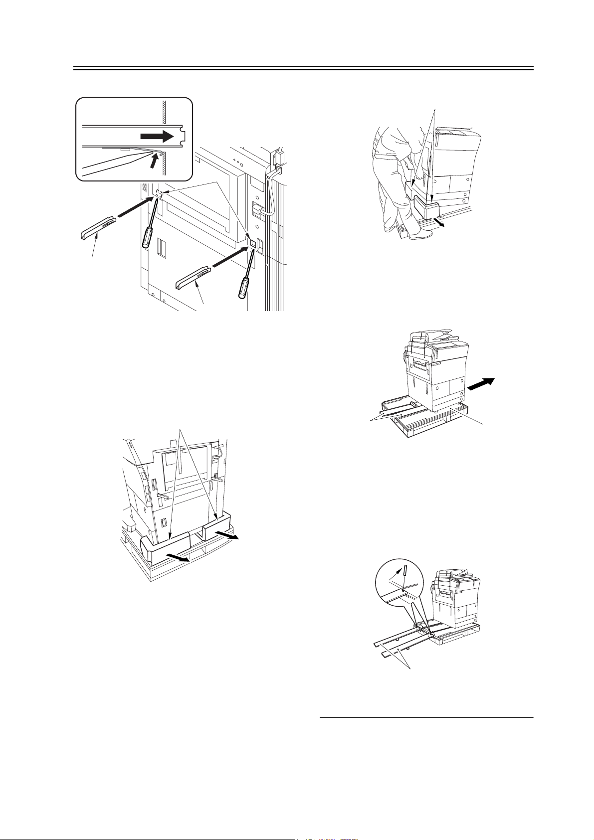
5) Move the machine in the direction of the arrow;
then, remove the 2 slope plates [2] from the middle
of the skid [1].
3) While holding the grips on the pickup side (front,
rear), lift the machine slightly, and remove the pad
[1] in the direction of the arrow.
(weight of the machine: about 230 kg)
[1]
F-1-7
4) While holding the grips on the delivery side (front,
rear), lift the machine slightly, and remove the pad
[1] in the direction of the arrow.
At this time, do not lift the machine more than nec-
essary. Otherwise, you can lose the balance.
(weight of the machine: about 230 kg)
[2]
[1]
F-1-9
6) Detach the 2 pins taped to the back of the slope
plate.
7) Turn over the slope plate [1], and set it as shown;
then, match the skid and the slope plate by their pin
holes, and insert the pin [2] (1 pc. each).
[2]
[1]
F-1-10
9
Page 18
Chapter 1
Check that the caster [1] has not rolled off the skid [2].
Also, Check that it has not ridden over the edge [3] of
the skid.
[1][2] [3]
F-1-11
8) While holding the grips on the delivery side of the
machine, move the machine along the slope plates
and off the skid.
9) Remove the packing tape from the machine.
10) Remove the two grips [2] by inserting a screw-
driver to the grip insert hole [1].
[1]
[2]
[2]
F-1-12
11) Attach the 2 included pickup assembly face plate
[2] over the holes [1] from which you have removed
the grips.
[1]
[2]
F-1-13
10
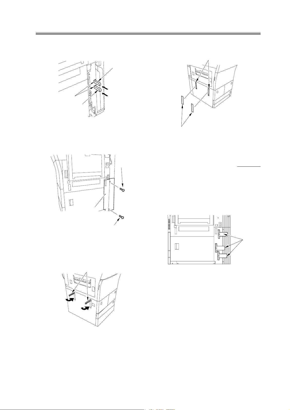
12) Remove the 2 screws [1], and rear right cover [2].
[1]
[2]
F-1-14
13) Insert the 2 grips [1] you removed in the foregoing
Page 19
Chapter 1
step in the compartment [2] found at the rear right
of the machine.
[1]
[2]
[1]
F-1-15
14) Attach the right cover (lower rear) [2] with 2
screws [1].
[1]
the grips.
[1]
[2]
F-1-18
1.2.4 Attaching the Pickup Assembly
iR C6800C / iR C6800CN / iR 5800C / iR 5800CN /
/ iR 5870Ci / iR 5870C / iR 6870Ci / iR 6870C
0002-6414
[2]
[1]
F-1-16
15) Store the 2 grips [1] on the delivery side as shown
so that they are inside the machine.
[1]
F-1-17
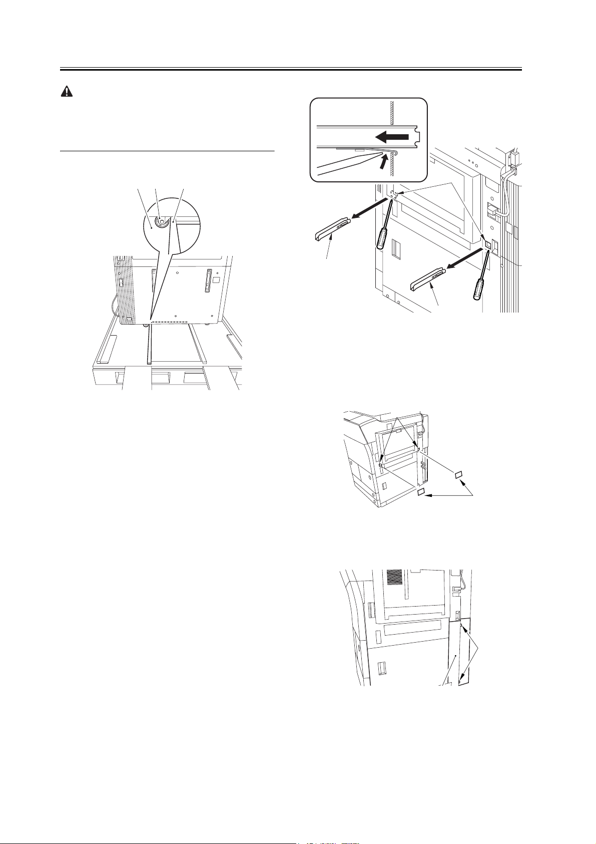
1) Remove the 3 shipping tags [1] from the right rear
lower cover.
[1]
F-1-19
2) Open the upper right cover [1] and the lower right
cover [2]; then, remove the 3 unlocking spacers [3]
from the pickup slot of the right deck and the cas-
settes.
16) Attach the 2 included delivery assembly face
plates over the holes [1] in which you have stored
11
Page 20
Chapter 1
[1]
[3]
[2]
F-1-20
To remove the release spacer, be sure first to push its
lever [1] in the direction of A before removing it in the
direction of B. removing the lever [1] of the release
spacer horizontally by mistake can damage the pickup
assembly. Take full care.
press on the release button. If so, remove the deck as-
sembly by hand.
5) Open the front cover.
6) Match the included left deck locking plate [1]
against the 2 holes in the left deck rear side plate;
then, secure it in place using a screw (RS tighten-
ing; M4x8) [2].
[2]
[1]
[1]
[A]
[B]
F-1-21
3) Close the upper right cover and the lower right cov-
er.
4) Press the release button, and remove the left deck.
F-1-22
- When attaching the left deck locking plate, take care
not to trap the left deck cable by the plate. (To facil-
itate the work, try lightly pressing down on the deck
cable.)
- Pull lightly on the deck cable to check that the cable
is not trapped.
7) Close the left deck.
1.2.5 Attaching the Scanner System
iR C6800C / iR C6800CN / iR 5800C / iR 5800CN /
/ iR 5870Ci / iR 5870C / iR 6870Ci / iR 6870C
0002-6566
The left deck is not supported by its locking plate, and
the deck assembly may not remove in response to a
12
1) Open the ADF, and remove the packing material.
2) Remove the screw [1] used to attach the scanner.
Page 21
1.2.7 Before Attaching
the Developing Assem-
Chapter 1
[1]
F-1-23
Advise the user to store away the screw used to fix the
scanner system in plate. It will be used when relocat-
ing the machine in the future.
1.2.6 Locking the Primary Transfer Roller in Place
iR C6800C / iR C6800CN / iR 5800C / iR 5800CN /
/ iR 5870Ci / iR 5870C / iR 6870Ci / iR 6870C
0002-6568
bly
iR C6800C / iR C6800CN / iR 5800C / iR 5800CN /
/ iR 5870Ci / iR 5870C / iR 6870Ci / iR 6870C
1) Pull the grip [1] toward the front to fully open the
upper right cover [2].
[1]
F-1-25
2) Remove the 2 screws [1], and remove the right cov-
er (upper) [2].
[2]
0002-6569
[2]
1) Lift the primary transfer roller locking lever [1] in
the direction of the arrow to lock the roller in place;
then, attach the primary transfer roller locking lever
[1] using the included binding screw (M4x8) [2].
[2]
[1]
F-1-24
[1]
F-1-26
3) Press the release button [1] of the right deck, and
slide out the right deck [2].
13
Page 22
Chapter 1
[1]
[2]
F-1-27
4) Remove the screw [1] found at the lower right;
then, remove the front cover strap [2].
[1]
F-1-30
8) Remove the 3 screws [1].
[1]
[1]
[2]
F-1-28
5) Remove the 2 screws [1] (binding) of the front cov-
er; then, fully open the front cover [2].
[1]
[1]
[2]
F-1-29
F-1-31
9) Close the black toner supply cover [1]; then, fully
open the hopper assembly [2].
[2]
[1]
F-1-32
10) Remove the 4 connectors [1] found at the upper
right.
6) Close the right deck.
7) Open the black toner supply cover [1].
14
Page 23

Chapter 1
[1]
[1]
F-1-33
11) Remove the 4 connectors [1] found at the upper
left.
[1]
[1]
[2]
F-1-36
14) Hold the drum fixing member [1] in place using
the drum stop tool [2]. Then, using a screwdriver,
remove the drum fixing screw [3].
As shown in the figure, be sure to remove the screw
on the protrusion [4] of the drum stop only after
matching it against the notch [5] in the drum flange.
[1]
F-1-34
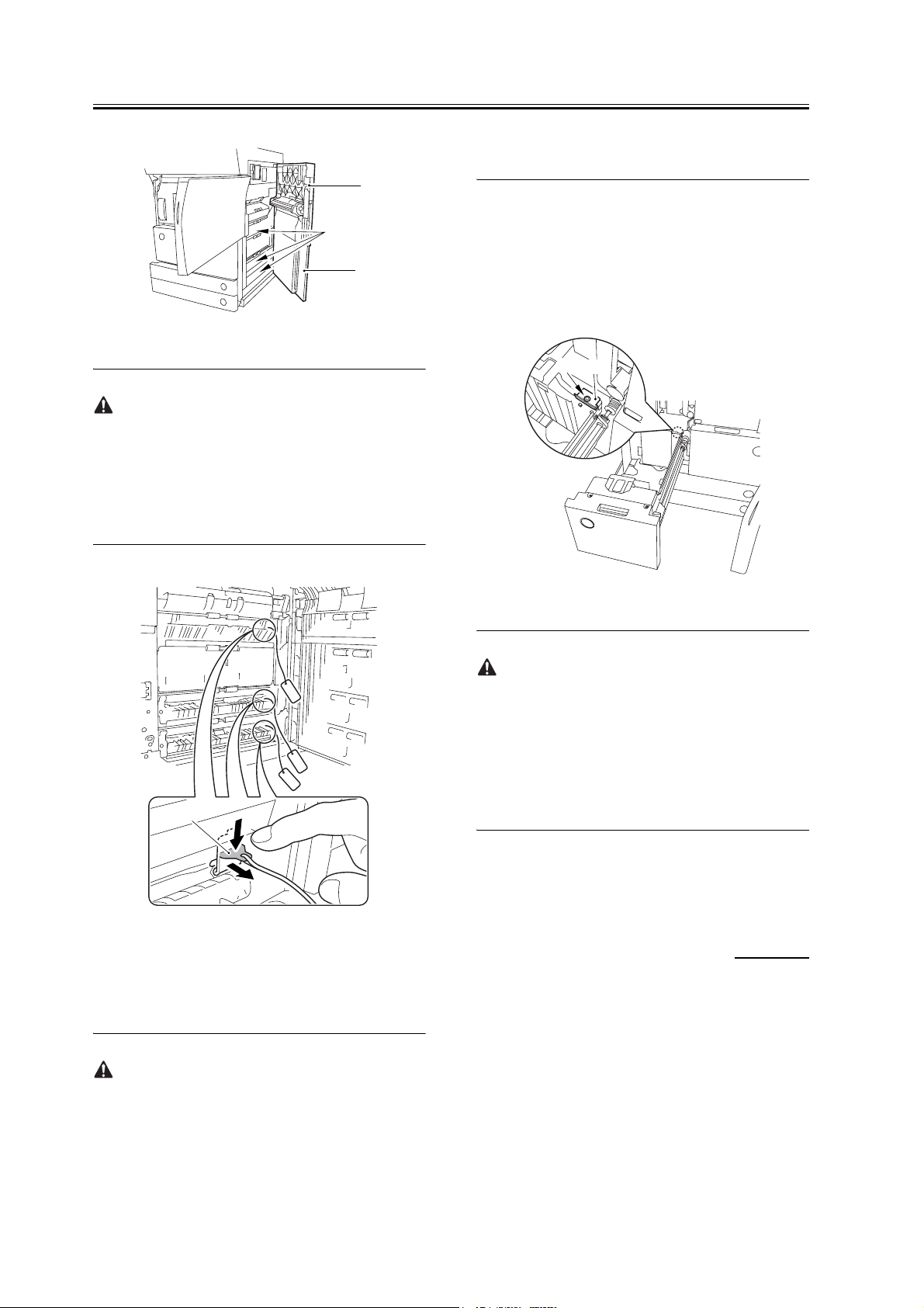
12) Remove the connector cable [1] of the high-volt-
age side from the 2 wire saddles [2] to avoid trap-
ping it. (Keep it on the cable hook [3] during the
work.)
[2]
[1]
[3]
F-1-35
13) Remove the process unit cover [1] from the box;
then, remove the drum stop tool [2] attached to its
back.
[1]
[3]
[2]
[5]
[4]
F-1-37
15) Remove the drum fixing member [1] using preci-
sion pliers.
15
Page 24

Chapter 1
[1]
F-1-38
16) Remove the 3 binding screws (M4x8) [1].
[1]
F-1-41
19) Press the 2 slide-out hook [1] found on both sides
of the fixing/feeding assembly, and fully slide out
the fixing/feeding assembly [2].
[2]
[1]
[1]
F-1-39
17) Shift down the fixing/feeding assembly releasing
lever [1] in the direction of the arrow.
[1]
F-1-40
18) Slide out the fixing/feeding assembly [1] to the
front.
[1]
F-1-42
20) Lift both ends [1] of the process unit slightly; then,
fully slide out the process unit [2] to the front.
16
Page 25

[2]
F-1-43
[1]
Chapter 1
1) Remove the color developing assembly (yellow,
magenta, cyan) from its package box.
2) Press the lever [1] of the developing rotary solenoid
once by hand; then, turn the developing rotary [2]
counterclockwise by hand.
If you turn the developing rotary clockwise with a col-
or developing assembly inserted in place, the anti-
stray sheet attached to the sleeve of the color develop-
ing assembly can come off by friction against the pho-
tosensitive drum. Be sure to turn the developing rotary
always in counterclockwise direction.
- Be sure to take care not to deform the joint plate
found at the left end when drawing out the process
unit.
- When drawing out the process unit, be careful not to
lift the process unit more than necessary. The unit
may slip off the rails, not permitting detachment.
- When you have slid out the process unit, try placing
paper between the photosensitive drum and the de-
veloping rotary to protect the drum from scratches
and light.
1.2.8 Attaching the Color
Developing Assemblies
iR C6800C / iR C6800CN / iR 5800C / iR 5800CN /
/ iR 5870Ci / iR 5870C / iR 6870Ci / iR 6870C
0002-6670
[1]
[2]
F-1-44
3) Turn the developing rotary so that its partition side
[1] is vertical (i.e., position for attaching the devel-
oping assembly).
If you keep pressing the lever of the developing rotary
solenoid, the developing rotary will not stop to permit
attaching the developing assembly. When you have
pressed the lever once, turn the developing rotary
slightly and then let go of the lever.
If you must touch a color developing assembly, be
sure that your hands are free of foreign matter (espe-
cially of metal) before doing so. (Adhesion of foreign
matter on the cylinder is likely to cause image faults.)
17
Page 26

Chapter 1
[1]
O
90
F-1-45
4) Remove the protective sheet [1] from the toner sup-
ply mouth of the developing rotary.
M
Y
C
6) Have the appropriate color developing assembly on
hand by checking the ID mark [1] attached to the
developing rotary assembly.
The following shows the ID mark attached to the
cyan color developing assembly.
M
Y
C
[1]
M
Y
C
F-1-48
[1]
F-1-46
5) Remove the 2 screws [1], and open the 2 develop-
ing assembly arms [2] in the direction of the arrow.
Be sure to attach the developing fixing arm with a
screw before turning the developing rotary.
[1]
[1]
[2]
[2]
7) Place A3 paper on a smooth table, and place the ap-
propriate color developing assembly.
8) With the developing cylinder of the color develop-
ing assembly facing upward, remove the tape [1];
then, remove the protective sheet [2] while holding
both its edges.
[2]
[1]
F-1-49
- Do not touch the developing cylinder.
- After finishing the foregoing step, be sure to change
the orientation of the color developing assembly so
that the sponge side faces upward.
18
F-1-47
9) Remove the tape [1], and remove the sponge.
Page 27

After removing sponges, toner or starting agent may
be spilled. Do not work with the supply mouth down.
F-1-50
Chapter 1
Try holding the color developing assembly by both its
ends to facilitate the work.
F-1-52
12) Close the 2 developing assembly fixing arms [1]
in the direction of the arrows; then, attach them us-
ing 2 screws [2].
10) Check for scratches on the developing cylinder
while turning the developing cylinder gear [1] 5 to
6 times in the direction of the arrow. The work also
serves to even out the starter inside the unit.
[1]
F-1-51
11) Make sure that the color developing assembly
matches the ID mark; then, attach it in the develop-
ing rotary.
To do so, start with the front of the color developing
assembly; while keeping its front fully against the
front of the developing assembly, fit its rear in
place.
[1]
[1]
[2]
[2]
F-1-53
13) Repeat steps from 2) to 12) to attach all 3 color de-
veloping assemblies in the developing rotary.
14) If the developing cylinder [1] is found as in the
figure marked NG, turn the developing rotary so
that it is positioned as shown in the figure marked
OK.
19
Page 28

Chapter 1
NG
OK
[1]
F-1-54
[1]
[1]
[2]
F-1-57
If you fail to release the torque limiter, you will not be
able to attach the locking plate of the black developing
assembly. Be sure not to leave out the work.
1.2.9 Attaching the Black
F-1-55
15) Loosen the screw [2] used to attach the torque lim-
iter [1] of the developing rotary; then, move it up-
ward to release.
[2]
[1]
F-1-56
16) Attach the torque limiter using a screw [1].
Developing Assembly
0002-6683
iR C6800C / iR C6800CN / iR 5800C / iR 5800CN /
/ iR 5870Ci / iR 5870C / iR 6870Ci / iR 6870C
If you must touch a black developing assembly, check
that your hands are free of foreign matter (especially
of metal) before doing so. (Adhesion of foreign matter
on the cylinder is likely to cause image faults.)
1) Remove the 2 screws [1], and remove the joint plate
[2].
20
Page 29

[2]
Chapter 1
[1]
F-1-58
2) Hold the black developing assembly in lengthwise
direction, and remove it out of its package box.
- The machine's black developing assembly is
equipped with a potential sensor. Do not touch the de-
tection window [1] of the sensor.
- Do not subject the black developing assembly to im-
pact to prevent damage to the potential sensor as by
dropping it.
- Be sure to place paper before placing the black de-
veloping assembly on the floor or a table.
[1]
F-1-59
[2]
[1]
F-1-60
4) Turn the developing cylinder gear by hand to check
for scratches on the cylinder.
5) Remove the tape [2] used to keep the high-voltage
cable [1] in place.
[1]
[2]
F-1-61
6) Hold the black developing assembly [1] by both its
ends; while keeping it level, attach it in place while
pressing it downward at an angle.
At this time, be sure that the boss [2] at the rear of
the developing assembly matches the left guide [3]
of the machine.
Be sure also that the rib [4] at the front of the devel-
oping assembly matches the right guide at the front
of the machine.
3) Turn the developing cylinder gear [1] by hand to
check for scratches on the cylinder.
Do not touch the area [2] of the developing cylinder
cover indicated in the diagram; otherwise, the blade
can leave its trace on the cylinder.
21
Page 30

Chapter 1
[4]
[1]
F-1-62
[5]
[2]
[2]
[3]
[1]
F-1-64
8) Insert the high-voltage cable [1] of the black devel-
oping assembly along the side of the toner supply
mouth [2].
[2]
When attaching the black developing assembly in the
machine, try keeping the high-voltage cable [1] on top
of the assembly. Otherwise, the cable can get trapped
when the assembly is put inside the machine.
[1]
F-1-63
7) Insert the cable [1] having the tube of the black de-
veloping assembly through the hole [2] indicated in
the figure.
[1]
F-1-65
9) Connect the connector [1] found at the inside front.
[1]
F-1-66
10) Attach the joint plate [1] using 2 binding screws
[2].
22
Page 31

[1]
Chapter 1
14) Close the process unit.
[2]
F-1-67
11) Remove the paper put between the photosensitive
drum and the developing rotary.
12) Attach the protrusion [1] of the included black as-
sembly locking plate into the positioning hole [2]
found at the rear of the machine.
[2]
[1]
Take care not to trap the cable found at the right front
of the machine by the process unit. Be sure to close the
process unit while the front cover is fully open.
If you cannot fit the process unit all the way to the
rear, go through the following:
Slide out the process unit, and turn the developing ro-
tary drive gear found on the host side slightly; there-
after, be sure to close the process unit.
1.2.10 Attaching the Process Unit
iR C6800C / iR C6800CN / iR 5800C / iR 5800CN /
/ iR 5870Ci / iR 5870C / iR 6870Ci / iR 6870C
0002-6689
F-1-68
13) Attach the black developing assembly locking
plate [1] in place using the included screw (binding;
M4x8) [2].
[1]
[2]
F-1-69
1) Match the area [1] where the resistance of the high-
voltage cable is found in the upper left of the front
against the 4 pins [2] of the host machine; then, at-
tach it using the 4 clamps [3].
[2][3]
[3]
[1][2]
F-1-70
2) Insert the 2 cables [1] into the cable clamp [2].
3) Connect the 2 connectors [3], and insert the 2 cables
[4] into the 3 cable guides [5].
23
Page 32

Chapter 1
]
[1] [2
[4][5]
6) Attach the cable [1] of the black developing assem-
bly using the harness guide [2].
[3]
F-1-71
4) Connect the 3 connectors [1], and insert the cable
into the 4 cable guides [2] and the 2 cable clamps
[3].
[1] [2]
[2]
[1] [2]
F-1-74
7) Connect the connector [1] coming from the black
developing assembly.
[1]
[1] [2] [3]
F-1-72
5) Connect four connectors [1] on the upper right of
the front side and fix them with a clamp [2].
[1]
[2]
F-1-73
F-1-75
8) Attach the process unit [1] using 3 binding screws
(M4x8).
[2]
[1]
[2]
F-1-76
24
Page 33

Be sure to use the binding screws. The use of RS tight-
ening screws in the area of aluminum die-casting can
damage the threads of the screws.
9) Attach the drum fixing member [2] to the drum
flange [1]; then, hold it in place using the drum stop
tool. Thereafter, tighten the drum fixing screw [4]
using a screwdriver.
Be sure to attach the protrusion [5] of the drum stop
tool with a screw while matching it against the notch
[6] of the drum flange.
Chapter 1
is between he markings [1] "." and ".." of the drum
flange.
[1]
F-1-78
[2]
[1]
[4]
[3]
[6]
[5]
F-1-77
- If the photosensitive drum is let to turn clockwise
during the work, the scoop-up sheet can become
soiled to cause stray toner. Be sure to hold the drum
stop tool firmly in place when tightening the drum
fixing screw.
- Check that the protrusion of the drum fixing member
- Be sure to attach the drum stop tool [2] to the back
of the process unit cover [1] for possible future re-
location of the machine.
[1]
[2]
F-1-79
10) Close the fixing/feeding assembly.
11) Loose the screw [1], and move the charging as-
sembly fixing [2] in the upper right direction; then,
attach it in place using a screw.
12) Remove the connector [3], and remove the prima-
ry charging assembly [4]. Check the primary charg-
ing wire and the shielding plate for soiling. If it is
soiled with dirt or paper lint, clean it using alcohol.
25
Page 34

Chapter 1
[4] [3]
[2][1]
F-1-80
13) Remove the connector [1], and remove the screw
[2].
14) Remove the pre-transfer charging assembly [3].
Check the pre-transfer charging wire and the
shielding plate for soiling. If it is soiled with dirt or
paper lint, clean it using alcohol.
[2]
[1]
[2]
F-1-82
19) Close the black toner supply cover [1].
[2] [3]
[1]
F-1-81
15) Attach the primary charging assembly and the pre-
transfer charging assembly.
16) Close the hopper assembly.
17) Open the black toner supply cover [1].
18) Attach the hopper assembly [1] using 3 screws [2].
[1]
F-1-83
20) Slide out the right deck.
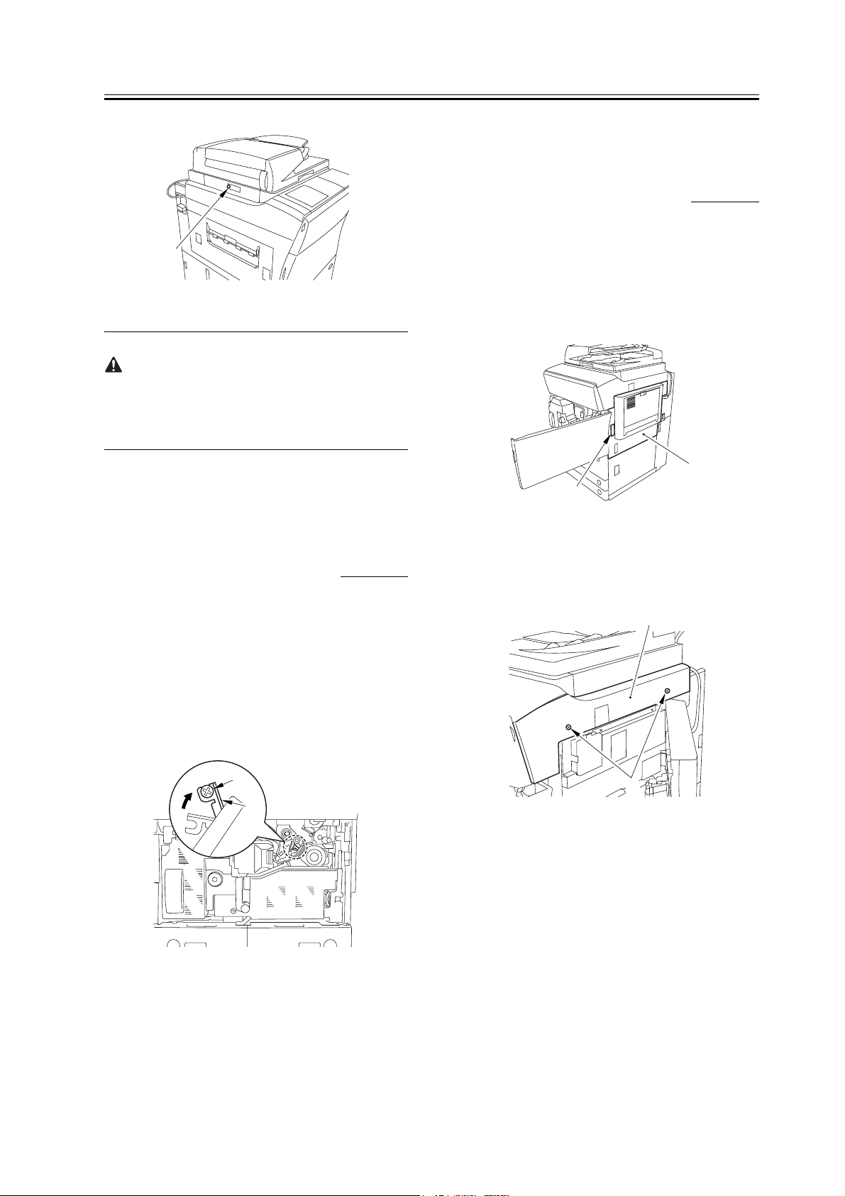
21) Attach the front cover hinge [1] using 2 binding
screws [2].
22) Attach the front cover strap [3] using a screw [3].
[2]
[4]
[2]
[1]
[3]
[1]
F-1-84
26
23) Close the right deck.
Page 35

Chapter 1
24) Slide out the fixing/feeding assembly.
25) Open the color toner supply cover [1].
[1]
F-1-85
26) Attach the process unit cover [1] using the 2 RS
tightening screws (M4x8) [2].
27) Close the color toner supply cover.
[2]
1.2.11 Attaching the Fixing Assembly
iR C6800C / iR C6800CN / iR 5800C / iR 5800CN /
/ iR 5870Ci / iR 5870C / iR 6870Ci / iR 6870C
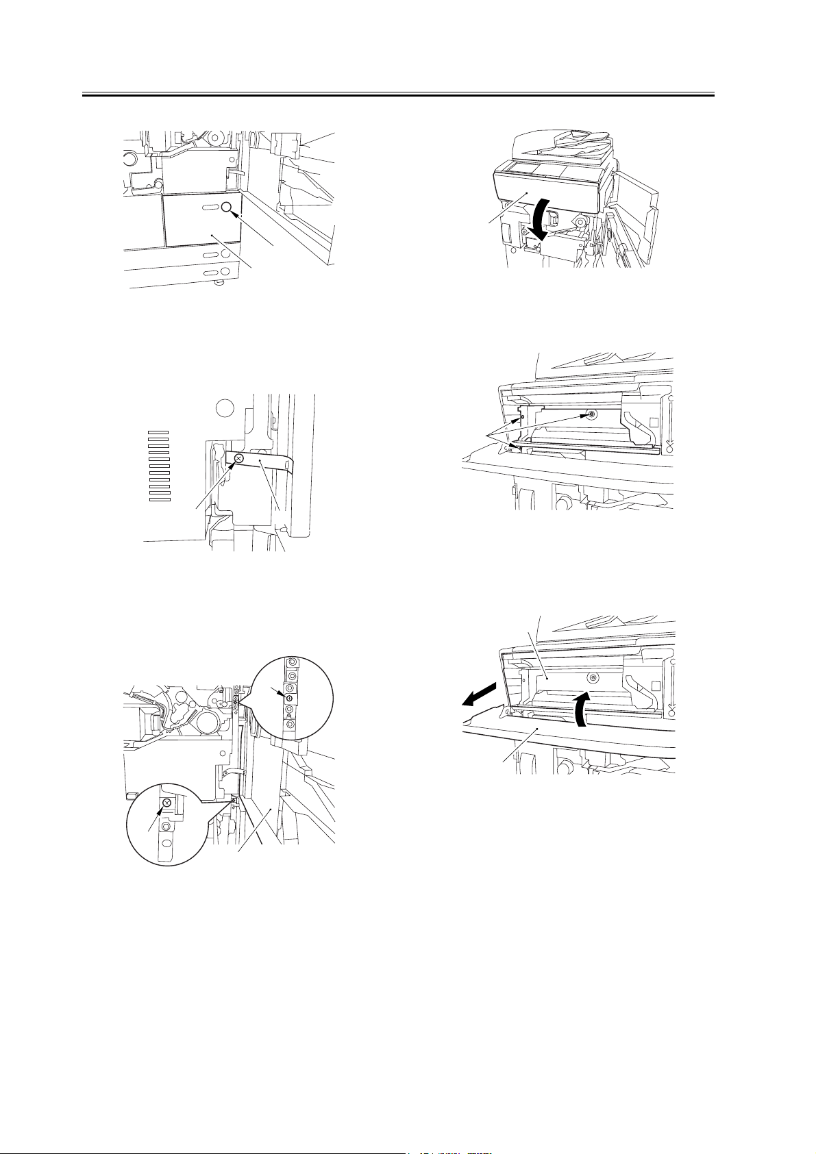
1) Slide out the fixing/feeding assembly fully.
2) Open the reversal delivery cover [1].
[1]
F-1-88
3) Open the middle cover [1].
0002-6697
[1]
[3]
F-1-86
28) Attach the right cover (upper) [1] with 2 screws
[2].
[1]
[2]
F-1-87
29) Close the right upper cover.
[1]
F-1-89
4) Remove the tape [2] used to keep the tag [1] in
place.
[1]
[2]
F-1-90
27
Page 36

Chapter 1
5) Remove the 2 fixing nip releasing screws [1].
[1]
[1]
F-1-91
6) Check the fixing web for any slack; as necessary,
perform steps 7) and 8).
7) Remove the 3 screws [1] and the fixing knob [2];
then, remove the fixing front cover [3].
9) Attach back the fixing front cover and the fixing
knob by reversing the work in step 7).
10) Close the middle cover.
11) Close the reversal delivery cover.
12) Close the fixing/feeding assembly.
13) Lock the releasing lever in place; then, close the
front cover.
1.2.12 Fitting the Black Toner Bottle
iR C6800C / iR C6800CN / iR 5800C / iR 5800CN /
iR 5870Ci / iR 5870C / iR 6870Ci / iR 6870C
1) Remove the black toner bottle from its packaging
box.
2) Open the black toner supply cover [1]; then, press
down the lock lever [2].
0002-6699
[1]
[3]
[1]
[2]
[1]
F-1-92
8) Turn the gear [1] counterclockwise (viewing the
machine from the front) to remove the slack.
[2]
[1]
F-1-94
3) Hold the black toner bottle [1] as shown in the fig-
ure; then, turn the cap [2] in the direction of the ar-
row to remove from the bottle.
[2]
[1]
28
F-1-93
F-1-95
[1]
4) Hold the black toner bottle with its mouth [1] on the
Page 37

right side; then, attach it in the supply case [2] of the
machine.
[2]
[1]
F-1-96
5) Shift the attach lever [1] upward to attach the black
toner bottle [2].
[1]
Chapter 1
1) Set the environment switch to suit the site of instal-
lation.
If the site is in a high humidity environment, turn on
the environment switch [1] (so that the drum heater
will go on regardless of the state of the main power
switch [2]).
ON
ON
[1]
[2]
F-1-97
6) Close the black toner supply cover.
If you turn on the main power without first attaching
the bottle in the machine, the black toner level meter
appearing on the control panel will indicate 25% as
the remaining level of toner. Check that the black ton-
er bottle has correctly been attached in the machine
before turning on the main power.
1.2.13 Checking the Environment Switch
iR C6800C / iR C6800CN / iR 5800C / iR 5800CN /
/ iR 5870Ci / iR 5870C / iR 6870Ci / iR 6870C
0002-6701
[2]
F-1-98
At time of shipment from the factory, the environment
switch is off.
1.2.14 Turning On the Main Power Switch
iR C6800C / iR C6800CN / iR 5800C / iR 5800CN /
/ iR 5870Ci / iR 5870C / iR 6870Ci / iR 6870C
0003-1015
29
Page 38

Chapter 1
- Be sure to remove all packing material from the cas-
sette before turning on the main power.
- In the case of the 230-V model, take out the power
cord from the shipping box; then, connect its one
end to the machine and the other end to the power
outlet.
- The rotary starts to rotate when the main power is
tuned on. Do not use the door switch actuator.
1) In the case of the 100V model, connect the ground-
ing wire to ground the machine.
2) Connect the machine's power plug to the power
outlet, and turn on the main power [1].
3) Execute the following in service mode to disable
initial rotation: COPIER>FUNCTION>IN-
STALL>AINR-OFF; then, set it to '1'.
[1]
F-1-99
Be sure to perform the foregoing service mode item
after turning on the power to disable initial rotation. If
the power is turned off and then on, the machine will
start initial rotation, possibly causing an error in its
image stabilization mechanism.
1.2.15 Setting Up the Paper Cassette
iR C6800C / iR C6800CN / iR 5800C / iR 5800CN /
/ iR 5870Ci / iR 5870C / iR 6870Ci / iR 6870C
1) Press the cassette release button, and slide out the
cassette to the front.
2) Check with the user to find out the type of paper to
use; then, check if the size configuration switch [1]
of the cassette is set to the desired paper type. If not,
set the cassette to suit the type.
3) Turn the paper size dial [2] to suit the desired paper
size.
0002-6732
30
Page 39

B5
B5
R
B4
F-1-100
[2]
Chapter 1
cassette.
9) Open the front cover; then, remove the color toner
cartridge supply tab [1] from its back.
[1]
[1]
4) Pick the lever [1] of the side guide plate, and move
the side guide plate to the desired size marking.
5) Remove the lever [2] of the rear end guide plate.
Fit the rear end guide plate to match the desired size
marking on the bottom plate of the cassette.
[2]
[1]
F-1-101
6) Attach the correct size label [1] to the front of the
cassette.
F-1-103
10) Remove the 2 color toner cartridge replacement
supply tab labels from the 2 base sheets on which
the cassette size label was found.
11) Attach the 2 color toner cartridge supply tab labels
[2] to the color toner cartridge replacement supply
tab [1].
[2]
[2]
[1]
F-1-104
[1]
F-1-102
7) Deposit paper in the cassette; then, slide the cas-
sette back into the machine.
8) As necessary, perform the same work for the other
12) Attach the color toner cartridge replacement sup-
ply tab to the back of the front cover; then, close the
front cover.
1.2.16 Changing the Deck Paper Size (right, left)
iR C6800C / iR C6800CN / iR 5800C / iR 5800CN /
/ iR 5870Ci / iR 5870C / iR 6870Ci / iR 6870C
0002-6733
31
Page 40

Chapter 1
1) Open the front cover.
2) Press the release button, and slide out the right
deck.
3) Remove the screws [4] (3 pc. in total), and remove
the rear end guide plate [1], left guide plate [2], and
right guide plate [3]. Then, attach them to suit the
needs of the user.
[2]
[1]
[4]
[3]
F-1-105
SZ-C2 (A4=0, B5=1, LTR=2).
8) Press the Reset key twice to end service mode.
1.2.17 Fitting the Color Toner Cartridge
iR C6800C / iR C6800CN / iR 5800C / iR 5800CN /
iR 5870Ci / iR 5870C / iR 6870Ci / iR 6870C
1) Remove the color toner cartridge (yellow, magenta,
cyan) from its packaging box.
2) Hold the color toner cartridge (yellow, magenta,
cyan) as shown with both hands, and turn it in the
direction of the arrows 10 times to even out the ton-
er inside it.
0002-6703
at time of shipment : A4 size (100/230V),LTR size
(120V)
4) Deposit paper in the right deck; then, attach it into
the machine.
5) Attach the size sticker [1] of the new paper size to
the frond of the deck.
[1]
F-1-106
6) As necessary, perform the same work on the left
deck.
7) After changing the size, execute the following in
service mode to register the front deck paper size:
for the right deck, COPIER>OPTION>CST>P-SZ-
C1; for the left deck, COPIER>OPTION>CST>P-
F-1-107
When turning the color toner cartridge, be sure not to
touch the shutter assembly or turn the knob; other-
wise, the toner can start to leak.
F-1-108
32
Page 41

3) Check to see that the control panel indicates the
message "Set the Toner Cartridge."
4) Open the front cover.
5) Open the color toner supply cover [1].
Chapter 1
11) Repeat steps 4) through 9) to attach the C toner
cartridge.
12) See that the control panel indicates the message
"Set the Toner Cartridge."
13) Repeat steps 4) through 9) to attach the M toner
cartridge.
1.2.18 Supplying Black
[1]
F-1-109
6) Insert the Y toner cartridge [2] through the color
toner cartridge slot [1].
[1]
[2]
F-1-110
7) Turn the lock lever [1] clockwise to attach the Y
toner cartridge [2].
[2]
Toner
iR C6800C / iR C6800CN / iR 5800C / iR 5800CN /
/ iR 5870Ci / iR 5870C / iR 6870Ci / iR 6870C
1) Check that the warm-up period is over (i.e., Keep
paper in the machine so that the control panel will
indicate the message "Ready to Copy").
2) Perform the following service mode item to supply
black toner: FUNCTION>INSTALL>TONER-S
(10 min avr; 13 min max.).
While this service mode item is under way, a count-
down is made on the control panel; at the end, 'OK!' is
indicated.
0002-6727
1.2.19 Cleaning the Intermediate Transfer Belt
iR C6800C / iR C6800CN / iR 5800C / iR 5800CN /
/ iR 5870Ci / iR 5870C / iR 6870Ci / iR 6870C
0002-6728
[1]
F-1-111
8) Close the color toner supply cover.
9) Close the front cover.
10) See that the control panel indicates the message
"Set the Toner Cartridge."
1) Perform the following service mode item to clean
the ITB: FUNCTION>CLEANING>TBLT-CLN
(about 20 seconds).
The notation "OK!" appears on the screen to indicate
the end of the service mode item.
33
Page 42

Chapter 1
1.2.20 Supplying Color Toner
iR C6800C / iR C6800CN / iR 5800C / iR 5800CN /
/ iR 5870Ci / iR 5870C / iR 6870Ci / iR 6870C
1) Perform the following service mode item to set up
color toner settings: FUNCTION>INSTALL>IN-
SET-3 (about 14 minutes).
- Do not turn off the power switch while the machine
is in operation.
- If the machine is turned off, the ITB may carry a de-
posit of toner, which can cause image faults. As nec-
essary, perform
COPIER>FUNCTION>CLEANING>TBLT-CLN
and then INISET-3 to correct the problem.
While this service mode item is under way, a count-
down is made on the control panel; at the end, "OK!"
is indicated.
This mode uses ATVC control, possibly taking a
while depending on the site environment. The count
on the screen, for this reason, may loop between 890
and 820.
2) Perform the following service mode item to supply
color toner: FUNCTION>INSTALL>SPLY-H-3
(about 45 seconds).
The notation "OK!" appears on the screen to indicate
the end of the service mode item.
0002-6729
1.2.21 Setting Auto Gradation Correction
iR C6800C / iR C6800CN / iR 5800C / iR 5800CN /
/ iR 5870Ci / iR 5870C / iR 6870Ci / iR 6870C
1) Clean the reading glass surface of the machine's
copyboard.
2) Press the User Mode key.
3) Make the following selections: adjust/cleaning>au-
to gradation correction>full correction>test print 1.
In a while, the machine prints out Test Print 1.
4) Place the printout (Test Print 1) on the copyboard
glass as indicated on the control panel.
5) Press [read start].
- The machine will read the printout of Test Print 1.
- When a message has appeared asking you to re-
move the printout, remove it from the copyboard
glass.
6) Press [test print 2].
In a while, the machine prints out Test Print 2.
7) Place the printout of Test Print 2 on the copyboard
glass as indicated on the control panel.
8) Press [read start].
- The machine will read Test print 2.
- When a message has appeared asking you to re-
move the printout, remove it from the copyboard
glass.
9) Press [test print 3].
In a while, the machine prints out Test Print 3.
10) Place the printout of Test Print 3 on the copyboard
as indicated on the control panel.
11) Press [read start].
- The machine will read Test Print 3.
- When a message has appeared asking you to re-
move the printout, remove it from the copyboard.
12) Press the Reset key to end User mode.
0002-6731
Do not turn off the power switch while the machine is
in operation.
34
Page 43

Chapter 1
1.2.22 Checking the Image/Operation
iR C6800C / iR C6800CN / iR 5800C / iR 5800CN /
/ iR 5870Ci / iR 5870C / iR 6870Ci / iR 6870C
1) Place the Test Chart on the copyboard glass, and
make copies using the cassettes and the deck as the
source of paper; then, check the output images.
- be sure there is no abnormal noise.
- be sure that images produced at different magnifi-
cations are all correct.
- be sure that as many copies as specified are made.
- be sure that the images are all correct regardless of
the source of paper used.
The output must satisfy the following standards:
- horizontal registration (margin on image left
edge): 2.5 +/-1.5 mm
- leading edge (margin on image leading edge): 4
+1.5, -1.0 mm
0002-6730
position of the adjusting plate [2].
[2]
[1]
F-1-112
- move the adjusting plate toward the rear to de-
crease the left margin.
- move the adjusting screw toward the front to in-
crease the left margin.
4) Check that the horizontal registration (left/right
margin; L1) of the copy on paper from cassette 3 is
2.5 +/-1.5 mm.
Reference:
If the output is not as indicated, see the instructions on
how to adjust the horizontal registration and leading
edge registration.
1.2.23 Adjusting the Horizontal Registration
iR C6800C / iR C6800CN / iR 5800C / iR 5800CN /
/ iR 5870Ci / iR 5870C / iR 6870Ci / iR 6870C
Adjust the horizontal registration as follows according
to the source of paper:
1. Cassette 3
1) Press the cassette release button, and slide out the
cassette 3 to the front.
2) Open the upper right cover and the lower right cov-
er.
3) Insert a screwdriver through the hole in the front
right stay; then, loosen the screw [1] to adjust the
0002-6734
[1]
L1
[1] Paper feed direction
5) Tighten the screw.
6) Close the upper right cover and the lower right cov-
er.
7) Fit the cassette 3 back in.
2. Cassette 4
1) Perform the steps given for the cassette 3 to adjust
the horizontal registration for the cassettes 4.
3. Left Deck
1) Press the release button, and slide out the left deck.
2) Remove the left face cover [1] using a flat-blade
screwdriver.
image
F-1-113
35
Page 44

Chapter 1
[1]
F-1-114
3) Loosen the 2 screws [1], and insert a screwdriver
through the hole in the front left stay; then, turn the
adjusting screw to adjust the horizontal registration.
[1]
[2]
F-1-115
4) Make a copy using the left deck as the source of pa-
per; then, check that the horizontal registration
(left/right; L1) is 2.5 +/-1.5 mm.
[1]
image
[1]
[2]
F-1-117
Turn the screwdriver counterclockwise so as to de-
crease the horizontal registration (left/right margin)
[1].
Turn the screwdriver clockwise so as to increase the
horizontal registration (left/right margin) [2].
A full turn of the screwdriver moves the horizontal
registration (left/right margin) by 1.0 mm.
6) Tighten the 2 screws you loosened in step 3).
7) Attach the left face cover you removed in step 2)
back on the machine.
8) Close the left deck.
4. Right Deck
1) Press the release button, and slide out the right
deck.
2) Open the upper right cover and the lower right cov-
er.
3) Loosen the 2 screws [1], and insert a screwdriver
[2] through the hole in the front right stay; then, turn
the adjusting screw to adjust the horizontal registra-
tion.
L1
F-1-116
[1] Paper feed direction
5) If the output is not as indicated, make the following
adjustments:
36
[1]
[2]
F-1-118
Page 45

4) Check that the horizontal registration (left/right
marking; L1) of the copy made on paper from the
right deck is 2.5 +/-1.5 mm.
Chapter 1
[1]
L1
image
F-1-119
[1] Paper feed direction
5) If the output is not as indicated, make the following
adjustments:
[1]
[2]
F-1-120
Turn the screwdriver counterclockwise so as to de-
crease the horizontal registration (left/right margin)
[1].
Turn the screwdriver clockwise so as to increase the
horizontal registration (left/right margin) [2].
A full turn of the screwdriver will move the hori-
zontal registration (left/right margin) by 1.0 mm.
6) Tighten the 2 screws you loosened in step 3).
7) Close the right deck.
[2]
[1]
F-1-121
2) Check to see that the horizontal registration (left/
right margin; L1) of the copy made on paper from
the manual feed tray is 2.5 +/-1.5 mm.
[1]
L1
image
F-1-122
[1] Paper feed direction
3) Tighten the screws you loosened in step 1) to attach
the slide guide in place.
1.2.24 Adjusting the
Leading Edge Regis-
5. Manual Feed Tray
1) Loosen the 2 screws [1], and move the slide guide
[2] to adjust the horizontal registration.
tration
0002-6735
iR C6800C / iR C6800CN / iR 5800C / iR 5800CN /
/ iR 5870Ci / iR 5870C / iR 6870Ci / iR 6870C
Adjust the leading edge registration as follows ac-
cording to the source of paper:
Check that the leading edge registration (leading edge
margin; L1) of the copy made on paper from the cas-
37
Page 46

Chapter 1
settes and the deck is 4.0 +1.5/-1.0 mm.
If not, go through the following:
- Select the service mode: COPIER>AD-
JUST>FEED-ADJ>REGIST.
- Then, change the setting to adjust.
(A change of '1' moves the leading edge registration
by 0.1 mm. A higher setting will move the image to-
ward the leading edge.)
L2
[1]
Image
F-1-123
[1] Paper feed direction
1.2.25 Securing the
[1]
[2]
[3]
F-1-124
Areas to Avoid
- inside the machine (behind the front cover)
- louver
- grip slot
Machine in Place
0002-6736
iR C6800C / iR C6800CN / iR 5800C / iR 5800CN /
/ iR 5870Ci / iR 5870C / iR 6870Ci / iR 6870C
1) If the machine is already at its site of installation,
attach it using the 2 adjusters.
2) Remove the double-sided tape from the back of the
service book case [1]; then, attach the case by
matching its right edge against the line marking [3]
found on the right side of the bottom plate [2] of the
machine.
Be sure to match the front edge of the service book
case against the front edge of the base plate of the ma-
chine.
3) As appropriate, attach the 3 included labels ([1],
[2], [3]) to the locations indicated in the figure:
[1] Do Not Copy label (non-Japanese model)
[2] Cleaning Instructions label (non-Japans model)
[3] ADF size label
[2]
[1]
F-1-125
Attaching the ADF Size Label
Spread the ADF size guide plate [1] fully; then, match
segment A of the plate and the A4/A3 marking of the
label [2].
38
Page 47

Chapter 1
PRINT (printout) to the Service Label attached behind
the front cover.
A4
A3
A
1.2.26 If Not Connected
[2]
to a Network
0005-3940
iR C6800C / iR C6800CN / iR 5800C / iR 5800CN /
/ iR 5870Ci / iR 5870C / iR 6870Ci / iR 6870C
[1]
F-1-126
4) Attach the touch pen [1] on the control panel.
[1]
F-1-127
5) Clean up the area around the machine, and fill out
the service book.
6) Make necessary settings in user mode (date, time)
and service mode (COPIER>OPTION>USER).
MEMO:
If the machine is not connected to a network, its con-
trol panel will display the message "Check Connec-
tion to the Network." To disable the message, set
the following service mode item to "0":
COPIER> OPTION> BODY> NWERR-SW (level 2)
1.2.27 Affixing the Shutdown warning label
iR 5870Ci / iR 5870C / iR 6870Ci / iR 6870C
For iR C6870/C5870 Series
1) Affix the Shut-down warning label (in an appropri-
ate language) [1] to the right cover (rear upper) of
the machine [2].
0011-7812
When shipped from the factory, the 230-V model is
set to English for its language of display. If needed,
change the setting.
7) Perform the following service mode item, and store
the output away in the service book case: COPI-
ER>FUNCTION>MISC-P>P-PRINT.
In the course of installing the machine, be sure to
record the various adjustment values indicated by P-
[1]
[2]
F-1-128
39
Page 48

Chapter 1
1.3 Checking the Connection to the Network
1.3.1 Overview
iR C6800C / iR C6800CN / iR 5800C / iR 5800CN /
/ iR 5870Ci / iR 5870C / iR 6870Ci / iR 6870C
Go through the steps herein only if the machine is con-
nected to a network.
If the user's network is based on TCP/IP, use the PING
utility to check that the Ethernet PCB has properly
been installed and the network settings have correctly
been made. If the user's network is based on IPX/SPX
or AppleTalk, you need not make this check.
If the machine is equipped with a network board and
yet not connected to a network, it will indicate an net-
work-related error message. To disable the indication
of such a message, use the following service mode
item (set it to "0"): COPIER>OP-
TION>BODY>NWERR-SCREW.
1.3.2 Using the PING Utility
iR C6800C / iR C6800CN / iR 5800C / iR 5800CN /
/ iR 5870Ci / iR 5870C / iR 6870Ci / iR 6870C
1) Select the followings in service mode: COPI-
ER>TEST>NETWORK>PING.
2) Enter the IP address of the machine using the key-
pad on the control panel; then, press [OK].
3) Press the Start key.
The machine will indicate 'OK' if the result of the
check is good and 'NG' if not good.
0002-6738
0002-6739
<NETWORK>
PING
[1]
[1] Result (OK/NG)
[2] IP address field
< 1/1 >
0. 0. 0. 0
F-1-129
<READY >
[2]
+/-
OK
1.3.3 Using a Remote Host Address
iR C6800C / iR C6800CN / iR 5800C / iR 5800CN /
/ iR 5870Ci / iR 5870C / iR 6870Ci / iR 6870C
You can also use a remote host address and perform
the PING utility to check if the connection to the net-
work is correct or not.
The term 'remote host address' refers to the IP address
of a PC terminal connected to and operating on the
TCP/IP network to which the machine is connected.
1) Inform the system administrator that you will be
checking the network connection using the PING
utility.
2) Check the system administrator for the remote
home address you can use.
3) Enter the remote home address to the appropriate
PING field.
- See if 'OK' has appeared to indicate that the con-
nection to the network is correct.
- If the machine indicates 'NG, ' the connection is
not correct; go through the following:
0002-6747
40
Page 49

Chapter 1
1.4 Troubleshooting the Network
1.4.1 Overview
iR C6800C / iR C6800CN / iR 5800C / iR 5800CN /
/ iR 5870Ci / iR 5870C / iR 6870Ci / iR 6870C
Go through the steps herein only if the machine is con-
nected to a network.
If the machine's connection to the network fails, sus-
pect the following causes:
- The connection between the network and the
Ethernet PCB is faulty.
- The machine's TCP/IP settings are incorrect.
- The Ethernet PCB is faulty, or is not attached cor-
rectly.
- The network is faulty.
To identify the cause, go through the following:
1.4.2 Checking the Connection of the Network
Cable
iR C6800C / iR C6800CN / iR 5800C / iR 5800CN /
/ iR 5870Ci / iR 5870C / iR 6870Ci / iR 6870C
1) Check if the network cable is correctly connected to
the Ethernet PCB.
- If yes, go to the next check.
- If no, correct it, and run a check using the remote
host address once again.
0002-6749
0002-6750
chine's TCP/IP settings are correct by performing
PING using a loopback address.
1) Enter a loopback address (127.0.0.1) in the appro-
priate PING field.
- If the result of the check is not good, check the ma-
chine's TCP/IP settings once gain, and perform
PING once again.
- If the result of the check is good, go to the follow-
ing check.
1.4.4 Using a Local Host Address
iR C6800C / iR C6800CN / iR 5800C / iR 5800CN /
/ iR 5870Ci / iR 5870C / iR 6870Ci / iR 6870C
A local host address is the machine's IP address, and it
comes back after reaching the network PCB when you
perform PING, enabling you to check whether the net-
work PCB is normal.
1) Enter the machine's IP address in the appropriate
PING field.
If 'NG' is indicated, go through the following
check/remedy, and perform PING once gain:
- The machine's IP address is not correct: check
with the system administrator to find out if the ma-
chine's IP address is correct and valid.
- The connection of the network PCB is faulty:
check the connectors used to connect the network
PCB.
- The network PCB is faulty: replace the network
PCB.
If 'OK' is indicated, suspect a fault in the user's net-
work environment; contact the system administrator
for appropriate correction.
0002-6752
1.4.3 Using a Loopback Address
iR C6800C / iR C6800CN / iR 5800C / iR 5800CN /
/ iR 5870Ci / iR 5870C / iR 6870Ci / iR 6870C
A loopback address comes back before it reaches the
network PCB; as such, you can check whether the ma-
0002-6751
41
Page 50

Chapter 1
1.5 Installing the Card Reader
1.5.1 Points to Note About Installation
iR C6800C / iR C6800CN / iR 5800C / iR 5800CN /
/ iR 5870Ci / iR 5870C / iR 6870Ci / iR 6870C
You need a Card Reader Attaching Kit-C1 for the in-
stallation.
1.5.2 Checking the Contents
iR C6800C / iR C6800CN / iR 5800C / iR 5800CN /
/ iR 5870Ci / iR 5870C / iR 6870Ci / iR 6870C
0002-6804
0003-0860
2. Card Reader Attaching Kit-C1
[1]
[1] Card reader mount 1 pc.
[2]* Joint plate 1 pc.
[3]* Screw (Bind; M4X6) 1 pc.
[4] Screw (RS tight; M4X10) 2 pc.
*Not use in this machine
1.5.3 Installation
[2] [3] [4]
F-1-131
0002-6753
1. Card Reader-C1
[1] [2] [3]
C
F-1-130
[1] Card Reader-C1 1 pc.
[2] RS tightening screw (M4x10) 1 pc.
[3] Toothed washer 1 pc.
iR C6800C / iR C6800CN / iR 5800C / iR 5800CN /
/ iR 5870Ci / iR 5870C / iR 6870Ci / iR 6870C
1) Make the following selections in the host machine's
service mode: COPIER>FUNCTION>IN-
STALL>CARD; then, enter a number (1 to 2001).
- Use the lowest number of the cards that will be
used by the usered.
- As many as 1000 cards, starting with the number
you enter, will be registered.
2) Turn off the host machine's main power switch.
3) Remove the 2 screws [1], and remove the right cov-
er (upper) [2].
42
Page 51

[1][2]
F-1-132
4) Attach the card reader base [1] using the 2 included
screws [2].
Chapter 1
[2] [3]
[1]
F-1-135
7) Route the card reader harness through the wire sad-
dle, and connect the connector [1].
[1]
[2][1]
F-1-133
5) Insert the harness [1] of the card reader through the
hole [2] in the card reader base.
[1] [2]
F-1-134
6) Attach the card reader [2] to the card reader base [3]
using the included screw and toothed washer [1].
F-1-136
8) Cut the section [1] of the right cover (upper) indi-
cated in the figure using nippers.
[1]
F-1-137
9) Attach the right cover (upper) you removed in step
3).
10) Turn on the main power switch, and check that a
message has appeared asking for a control card.
11) Insert a control card, and check that the machine
is ready to make copies.
43
Page 52

Chapter 1
1.5.4 Using the Card
Reader in Combination
with NetSpot Accountant (hereafter, NSA)
iR C6800C / iR C6800CN / iR 5800C / iR 5800CN /
/ iR 5870Ci / iR 5870C / iR 6870Ci / iR 6870C
1) Make the following selections in Additional Func-
tion: system control settings>group ID con-
trol>count control; then, check to see IDs 00000001
thorough 00001000 have been created (i.e., if you
entered '1' as the first number in service mode):
COPIER>FUNCTION>INSTALL>CARD).
2) Make the following selections in Additional Func-
tion: system control settings>network set-
tings>TCP/IP settings>IP address; then set up the
following: IP address, gateway address, subnet
mask.
Take care. If you fail to register [system control
group] and [system control ID No.], you will not be
able to perform 'register card to device' as part of
NSA setup work.
0002-6799
3) Under [system administrator info] of Additional
Function, enter any number for [system control
group] and [system control ID No.].
4) Turn off the control panel switch.
5) Turn off and then on the main power switch.
44
Page 53

Chapter 1
1.6 Installing the NE Controller-A1
1.6.1 NE Controller-A1 Installation Procedure
iR C6800C / iR C6800CN / iR 5800C / iR 5800CN /
/ iR 5870Ci / iR 5870C / iR 6870Ci / iR 6870C
Installation procedure on the iR C6800 series is only
described here. Regarding setting methods, operation
check and notes, refer to the installation manual sup-
plied with this machine.
1) Detach the upper cover of controller (Refer to the
installation manual).
2) Connect the plug of AC adapter to the controller
(Refer to the installation manual).
3) Unscrew 4 screws [1] and detach the blanking plate
[2] of the rear cover (upper).
0003-6957
[2]
F-1-139
5) Mount the controller [1] on the rear cover (upper)
using 4 screws supplied with the controller.
F-1-140
[1]
[2]
[1]
[2]
[2]
[1]
F-1-138
4) Connect the cable [1] of controller to the connector
[2] of the copier.
6) Take the slack out of the cables between the iR host
machine and the controller, make bundles of them
at the side of host machine, and fix them with the
cable clamp [1].
[1]
F-1-141
7) Make necessary settings and check operations by
following the installation manual for NE controller-
A1.
45
Page 54

Chapter 1
1.7 Installing the Original Tray
1.7.1 Checking the Contents
iR C6800C / iR C6800CN / iR 5800C / iR 5800CN /
/ iR 5870Ci / iR 5870C / iR 6870Ci / iR 6870C
[1] Original holder 1 pc.
[2] Stepped screw (M4) 2 pc.
0002-6801
[1]
[2]
F-1-143
2) Hook the original holder [1] on the stepped screws
you attached in step 1).
[1]
[1] [2]
F-1-142
1.7.2 Attachment
iR C6800C / iR C6800CN / iR 5800C / iR 5800CN /
/ iR 5870Ci / iR 5870C / iR 6870Ci / iR 6870C
1) Attach the 2 stepped screws [2] in the right cover
(upper) [1].
0002-6754
F-1-144
46
Page 55

Chapter 1
1.8 Installing the Key Switch Unit-A1
1.8.1 Checking the Contents
iR C6800C / iR C6800CN / iR 5800C / iR 5800CN /
/ iR 5870Ci / iR 5870C / iR 6870Ci / iR 6870C
[1] Key switch unit 1 pc.
[2] Control key 1 pc.
[3] Binding screw (M4x6) 1 pc.
[1]
[2]
0003-1366
[3]
[2]
[3]
[1]
F-1-146
6) Cut off the section [1] of the right cover (upper rear)
indicated in the figure.
F-1-145
1.8.2 Attachment
iR C6800C / iR C6800CN / iR 5800C / iR 5800CN /
/ iR 5870Ci / iR 5870C / iR 6870Ci / iR 6870C
1) Turn off the control panel power switch.
2) Turn off the main power switch.
3) Remove the power plug.
4) Remove the reader communications cable [1].
5) Remove the 2 screws [2], and detach the right cover
(upper rear) [3].
0002-6756
[1]
F-1-147
7) Remove the 2 screws [1], and remove the plate [2].
[2][1]
[1]
F-1-148
8) Insert the protrusion [1] of the key switch into the
plate [2]; then, attach it using the included screw
[3].
47
Page 56

Chapter 1
[1] [2] [3]
F-1-149
9) Insert the harness [1] of the key switch through the
wire saddle [2].
[2]
[1]
F-1-150
10) Connect the connector [1] of the key switch.
[1][2]
[2]
F-1-152
12) Attach the right cover (upper rear) you removed in
step 5).
13) Insert the power plug, and turn on the main power
switch.
14) Start service mode, and make the following selec-
tions: COPIER>FUNCTION>INSTALL>KEY:
then, enter '1'.
15) Turn off and then on the main power switch.
16) Check that a message has appeared asking for the
control key.
17) Insert the control key, and check that the machine
is ready to make copies.
[1]
F-1-151
11) Attach the plate (key switch) [1] using the 2
screws [2] you removed in step 7).
48
Page 57

Chapter 1
1.9 Installing the Reader Heater Kit
1.9.1 Checking the ComponentsÅiReader
Heate-C1Åj
iR C6800C / iR C6800CN / iR 5800C / iR 5800CN /
/ iR 5870Ci / iR 5870C / iR 6870Ci / iR 6870C
0011-7561
[3] Disconnect the power cable (from the power out-
let).
iR C6870/C5870 Sereis
Turning Off the Main Power
When turning off the main power, be sure to go
through the following in strict sequence to protect the
machine's hard disk:
[1] Hold down on the power switch on the control
panel for 3 sec or more.
[2] Operate on the touch panel according to the shut-
down sequence indicated so that the main power
switch may be turned off.
[3] Turn off the main power switch.
[4] Disconnect the power cable (for the power outlet).
1.9.3 Installation Proce-
[1]
1. Mirror heater 1 pc.
2. Lens heater 1 pc.
3. Cable clamp 2 pc.
4. Heater harness retainer 1 pc.
5. RS tightening screw (M4x8) 4 pc.
[2]
[3]
F-1-153
[4]
[5]
1.9.2 Before Starting the Work
iR C6800C / iR C6800CN / iR 5800C / iR 5800CN /
/ iR 5870Ci / iR 5870C / iR 6870Ci / iR 6870C
iR C6800/C5800 Sereis
0011-7568
dure
iR C6800C / iR C6800CN / iR 5800C / iR 5800CN /
/ iR 5870Ci / iR 5870C / iR 6870Ci / iR 6870C
1) Open the ADF.
2) Remove the 2 screws [1], and detach the glass re-
tainer [2].
3) Remove the copyboard glass [3].
[3]
F-1-154
0011-7565
[1]
[2]
Turning Off the Main Power
[1] Turn off the control panel power switch.
[2] Turn off the main power switch.
49
Page 58

Chapter 1
When removing the copyboard glass, be sure to take
care not to touch the glass surface and the white plate
behind it.
If soiling is found, clean it using lint-free paper.
[A]
F-1-157
[1]
F-1-155
4) Pick the cut-up (bend) [A] of the mirror stay shown
in the figure, and move the No. 1 mirror base [1]
fully to the right.
[A]
F-1-158
5) Fit the front side of the mirror heater [1] to the side
plate, and connect the connector [2]; then, secure it
in place using 2 screws [3].
[2]
[3][1]
F-1-159
6) Secure the heater harness retainer [1] with a screw
[2].
50
F-1-156
Page 59

[1]
[2]
Chapter 1
that the claw of the heater [1] will not open. Also,
check to be sure that the bottom of the heater is firmly
in contact.
[A]
F-1-160
7) Move the No. 1 mirror base [1] fully back to the
left.
[1]
F-1-161
8) Connect the lens heater [1] to the connector [2];
then, secure it in place using a screw [3].
[2]
[1]
F-1-163
[A]
[1]
[3][1]
F-1-162
Move it fully so that there is no gap in the direction of
[A], and tighten the screw. At this time, take care so
F-1-164
9) Fit the cable clamp into the hole [A] of the frame;
then, fix the cable [1] in place using the clamp.
51
Page 60

Chapter 1
[1] [A]
F-1-165
If the vertical size sensor kit exits, check to be sure
that the cable is fitted to the 2 clamps [A] as shown in
the figure.
[2] [1]
F-1-167
[A]
F-1-166
10) If the cable is slack, fit the cable clamp [1] as
shown, and fix the cable [2] in place using the cable
clamp.
[1]
F-1-168
11) Mount the copyboard glass and the glass retainer
by reversing the steps used to remove them.
12) Turn on the machine's environment switch.
52
Page 61

1.10 Installing the Voice Guidance Kit
Chapter 1
1.10.1 Checking Items in the Package
iR 5870Ci / iR 5870C / iR 6870Ci / iR 6870C
Below are the items included in the Voice Guidance Kit-A2 packege.
[1] [2] [3]
[7]
[8]
[9]
[10]
[11] [12] [13]
[4]
[5]
[14]
0011-5499
[6]
[15]
[16] [17]
F-1-169
[1] Speaker unit (upper) 1 pc.
[2] Speaker unit (lower) 1 pc.
[3] Cable (1300mm) 1 pc.
[4]* Cable (1850mm) 1 pc.
[5] Cord guide (4 cord guide to be used) 7 pc.
[6] Voice Guidance Board 1 pc.
[7]* Voice Guidance Board Face Plate 1 pc.
[8] Voice Guidance Board Face Plate 1 pc.
[9] Binding screw (M3X6) 2 pc.
[10] Binding screw (M4X6) 1 pc.
[11] Binding screw (M4X40) 2 pc.
[12]* Binding screw (M3X16) 1 pc.
53
Page 62

Chapter 1
[13]* Binding screw (M4X16) 1 pc.
[14] Ferrite core 1 pc.
[15]* Clamp 1 pc.
[16] Users Guide 1 pc.
[17] User Manual CD-ROM 1 pc.
*Not to be used for this machine
1.10.2 Turning Off the Host Machine
0011-5500
iR 5870Ci / iR 5870C / iR 6870Ci / iR 6870C
Turning Off the Main Power
When turning off the main power, be sure to go through the following in strict sequence to protect the machine's hard
disk:
[1] Hold down on the power switch on the control panel for 3 sec or more.
[2] Operate on the touch panel according to the shut-down sequence indicated so that the main power switch may be
turned off.
[3] Turn off the main power switch.
[4] Disconnect the power cable (for the power outlet).
1.10.3 Installation Procedure
0011-5502
iR 5870Ci / iR 5870C / iR 6870Ci / iR 6870C
1. Installation Procedure
1) Open four cable clamps [1] to release a reader communication cable [2].
54
[2]
[1]
F-1-170
Page 63

2) Unscrew 7 screws [1] and detach the rear cover (upper) [2].
[1]
[2]
[1]
F-1-171
3) Unscrew 16 screws [1] and detach the controller box cover [2].
Chapter 1
[2]
[1]
[1]
[1]
[1]
F-1-172
4) Mount the facing plate [2] to the voice board [1] by 2 binding screws (M3X6) [3].
55
Page 64

Chapter 1
[3]
[1]
[2]
F-1-173
5) The slide switch SW1 found on the voice guidance board is set to 33 MHz at time of shipment; be sure to set it to
66 MHz for use on this machine.
66MHz
F-1-174
Checking the slide switch SW1 on the voice guidance board
The slide switch (SW1) on the Voice Guidance Board-A1 is provided as a means of switching frequencies (33 MHz/
66 MHz) to suit the transfer speed of the PCI bus. It is important for the switch setting to suit the transfer speed so
that the voice will be free of interruption.
For the machine, 66MHz is the correct position of the switch.
56
Page 65

33MHz
66MHz
F-1-175
6) Unscrew 2 screws [1] and detach the blanking plate [2].
Chapter 1
[1]
[2]
F-1-176
7) Insert the voice board [1] and mount it with two screws [2] which were unscrewed at the previous step.
Be sure to insert the board in the vertical direction to the connector.
57
Page 66

Chapter 1
[1]
F-1-177
[2]
[1]
F-1-178
8) Attach the controller box cover.
9) Attach the rear cover (upper).
10) Insert the reader communication cable and fix it with cable clamp.
11) Mount the speaker unit (lower) [1] on the upper right cover of main body with two screws (Bind; M4X40).
58
Page 67

Chapter 1
[1]
[2]
F-1-179
12) Mount the speaker unit (upper) [1] on the speaker unit (lower) mounted at the previous step, and fix it using a
screw (Bind; M4X6) [2] from beneath.
[1]
[2]
F-1-180
13) Remove a cord guide cover [1].
[1]
F-1-181
14) Peel off the release paper of cord guide [1] and affix them as shown in the figure.
Right side --- 1 position
59
Page 68

Chapter 1
Back --- 3 positions
[1]
F-1-182
[1]
[1]
[1]
F-1-183
15) Plug the cable [2] into the speaker unit [1].
[1]
[2]
F-1-184
16) Run the cable [1] through the cord guide [2] and mount the cord guide cover [3].
Be sure that there is no slack of the cable.
60
Page 69

Right side --- 1 position
Chapter 1
[2]
Back --- 3 positions
[1]
[2]
17) Mount the ferrite core [1] on the cable.
The length [2] should be less than 50mm.
[2]
[3]
[1]
F-1-185
[2]
[3]
F-1-186
[1]
F-1-187
18) Plug the cable [1] into the terminal [2] of voice board.
[2]
61
Page 70

Chapter 1
[1]
[2]
F-1-188
19) Plug the power cable of host machine into a wall outlet.
20) Turn on the main power switch.
21) Check if the voice board is recognized.
Enter service mode (" "->"2"& "8"at the same time ->" ")
COPIER > DISPLAY > ACC-STS > PCI1
If 'voice board' is indicated for PCI1, the board is correctly recognized by the machine.
3. Making Settings After Installation
To make use of the Voice Guidance Kit-A2 after turning on the host machine, you need to make the following set-
tings in Additional Function:
Additional Function > System Setting > Voice Guide Manegement Setting > Use Voice Guide.
1) Select [ON].
2) Press [OK].
default : OFF
4. Checking the Operation
- To Enable
1) Hold down the Reset key 3 sec or more.
2) See that the copy count on the screen is enclosed in red, indicating 'Voice Guidance' is ready for use.
- To Disable
1) Hold down the Reset key for 3 sec or more.
62
Page 71

Jan 25 2006
Page 72

 Loading...