

QT5-7282-V1 ©CANON INC. 2013 PRINTED IN CHINA
Setup Guide
ENG
Introductory Information
Series
1
Introduction
Read this manual before attempting to operate the printer.
Keep this manual in a handy location for future reference.
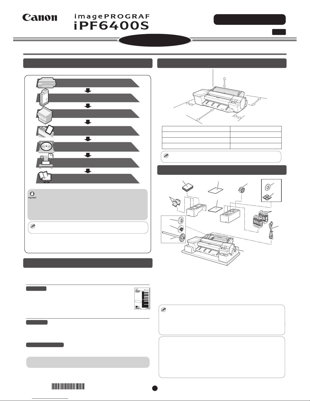
Overview of Setup
These are the steps in printer installation.
Load Paper to Adjust the Printheads
(P.5)
How to Display the Electronic
Manuals
(P.6)
Attach the Ink Tanks
(P.3)
Install the Printheads
Install the Software
(P.4)
Preparations
(P.2)
Store Accessories in the Pockets
(P.11)
(P.11)
• Even if you do not use the printer driver, be sure to install Media
Configuration Tool from the provided User Software CD-ROM. With
Media Configuration Tool, the paper types that are available in your
area can be registered to the printer. For instructions on installation,
refer to "Install the Software" on page 6. (In Windows, select Install
Individual Software in the Setup Menu window to install Media
Configuration Tool only.)
MEM
O
• We recommend doing a color calibration after completing the setup
to adjust variations in the colors.
Details for each step are given in this Setup Guide. Simply follow the instructions
to install the printer.
If an error message is displayed during setup or other problems occur, refer to
"Responding to Messages" on page 12.
The Manuals Supplied with This Printer
After installing the printer as shown in this Setup Guide, refer to the
manuals for instructions on operation and maintenance.
Printed Manuals
Basic Guide
The Basic Guide describes the following information.
• Loading paper, Replacing the consumables, Control Panel menus,
and others
• Troubleshooting tips and Error messages
• Preparations for transferring the printer
Electronic Manuals
User's Guide
This guide describes advanced usage of the printer such as paper saving tips,
how to print a poster and banner with the supplied software and print quality
adjusting method, in addition to the basic instructions for printing on roll paper or
cut sheet.
Paper Reference Guide
This guide describes about the types and specifications of the available media on
the printer.
To refer to the electronic manuals Refer to "How to Display the Electronic
Manuals" (P.11)
Space Required for Installation
+300mm
+300mm
+800mm
+150mm
+150mm
Printer Installation space (W x D x H mm)
Printer alone 1527 × 1802 × 644 mm
With stand attached 1527 × 1970 × 1301 mm
With stand and spectrophotometer unit attached 1527 × 2070 × 1301 mm
MEM
O
• A space of 1300 mm in the front and 700 mm in the back are needed
to print from the front paper feed slot.
Package Contents
a
g
j
i
l
b
h
m
c
k
d
e
f
a. Printer
b. Set of manuals
c. Printhead (x2)
d. 2-inch paper holder stopper
e. 3-inch paper holder stopper
f. Roll holder
g. Included paper
h. Setup Guide (this document)
i. 3-inch paper core attachment
j. Spacer for borderless printing
k. Set of CD-ROMs
l. Starter ink tanks (for first-time installation)
(Y, PC, C, GY, BK, PM, M, MBK)
m. Power cord
MEM
O
• Some of the items included in the package are not explained in this
Setup Guide, such as the spacer for borderless printing.
Keep these items in a safe place after setup because they are used in
various printing applications.
• For instructions on the included items not described in this manual, refer
to the User's Guide.
•
A cable to connect the printer to a computer is not provided with the printer.
• Canon, the Canon logo, and imagePROGRAF are trademarks or registered trademarks of CANON
INC.
• Microsoft is a registered trademark of Microsoft Corporation.
• Windows is a trademark or registered trademark of Microsoft Corporation in the U.S. and/or other
countries.
• Windows Vista is a trademark or registered trademark of Microsoft Corporation in the U.S. and/or
other countries.
• Mac, Macintosh, OS X and Bonjour are trademarks of Apple Inc., registered in the U.S. and other
countries.
• All other trademarks or registered trademarks described in this Setup Guide are the property of their
respective owners.
*QT57282V1*
2
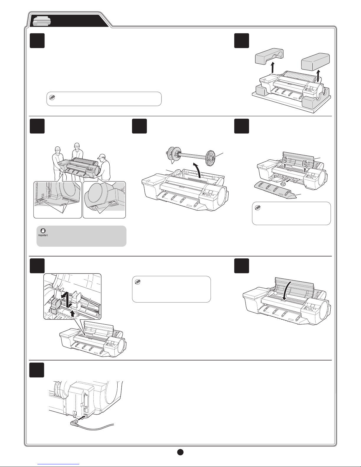
Prepare the printer for use by installing it and connecting the power cord.
Preparations
1
Install the printer. You can use the following three methods for installing the printer.
• Install without a stand on a table
Proceed to step 2.
• Install with the optional stand
Assemble the stand and install the printer referring to the Printer Stand Setup Guide included
with the stand.After installation, proceed to step 4.
• Install with the spectrophotometer unit
The stand is required if you are using the spectrophotometer unit. Assemble the stand and
install the spectrophotometer unit and printer by referring to the Printer Stand Setup Guide
and then the "SU-21 Spectrophotometer Unit Setup Guide". After installation, proceed to step 4.
MEM
O
• The stand is a standard accessory in some locations.
2
Remove the printer from the box and
remove the packing materials from the
top of the printer.
3
At least three people are needed to lift the
printer by its carrying handles (a), located
under its right and left ends, and to place
it on a table or other flat surface.
a
a
• The printer weighs approximately 54 kg
and requires at least three people to lift
it by its carrying handles (a) under its
right and left ends.
4
Remove all the orange tape from the roll
feed unit (a). Remove the roll holder (b)
from the roll feed unit (a) and remove the
protective materials and all the orange
tape on the two holder stoppers (c).
b
c
a
5
Remove the orange tape on the top cover
(a) and the ejection guide (b) and all the
packing materials.
After removing the orange tape and
packing material from inside the ejection
guide (b), reattach it.
a
b
MEM
O
• If the Spectrophotometer Unit
(optional) is attached, the
Ejection Guide (b) does not need
to be reattached.
6
Lift the belt stopper (b) from the carriage
shaft (a) and pull it towards you to remove
it.
a
b
b
MEM
O
• The belt stopper is used when
transporting the printer. Keep
the belt stopper after removing
it, in case the printer needs to be
moved again.
7
Close the top cover.
8
Plug the power cord into the power supply
connector on the back of the printer and
plug the other end into an electric outlet.
3
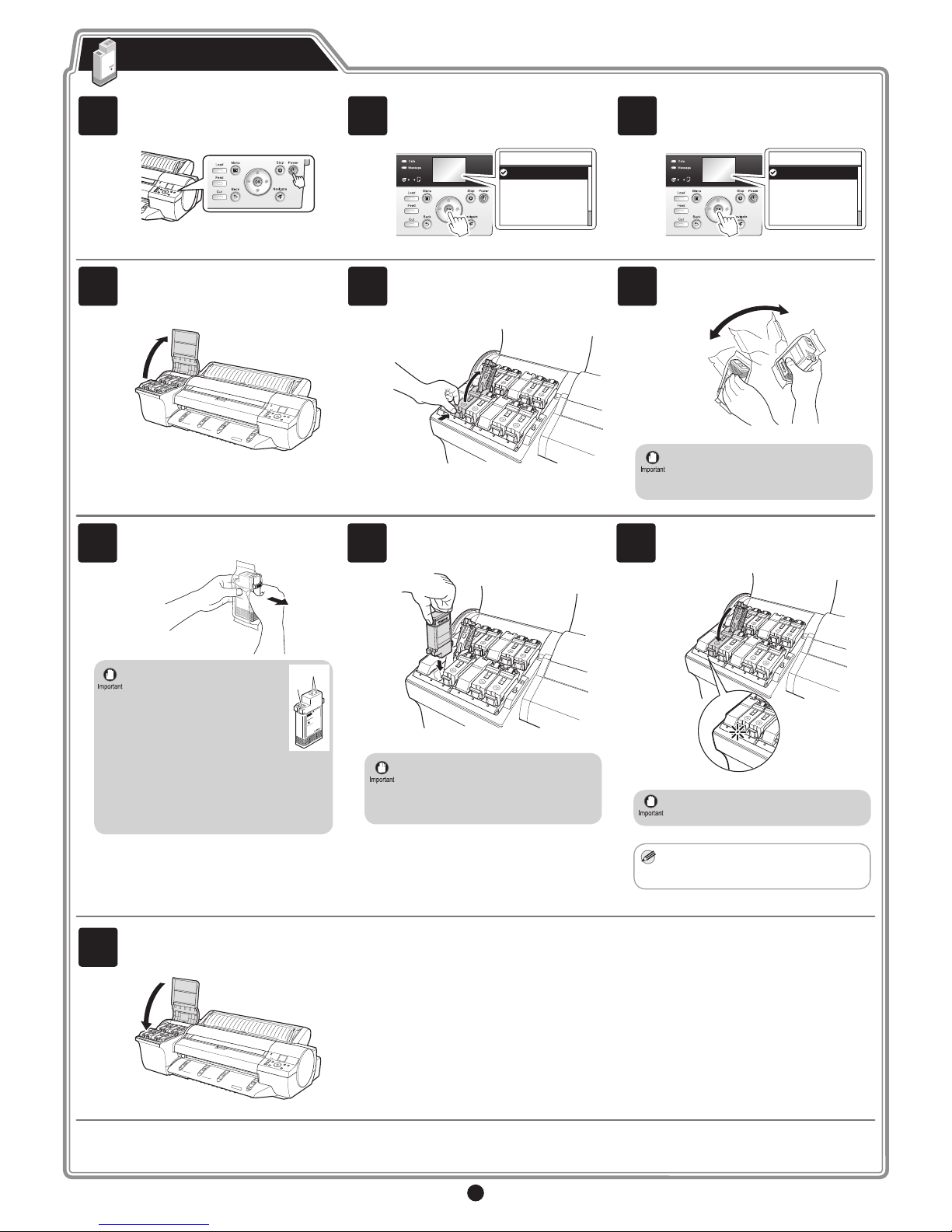
Install the 8 ink tanks.
Attach the Ink Tanks
1
Press the Power button to turn on the
printer.
2
When the following screen appears, use
the ▲ and ▼ keys to select a language
and press OK.
㪈㪆㪉
Language
English
ᣣᧄ⺆
Français
Italiano
Deutsch
3
Select your local time zone and press
OK.
㪈㪆㪌
Time Zone
0:London (GMT)
+1:Paris,Rome
+2:Athens,Cairo
+3:Moscow
+4:Eerevan,Baku
4
The procedure for attaching the Ink Tanks
(guidance) is displayed on the display.
Open the Ink Tank Cover by grasping the
handles according to the display.
5
While pressing the stopper of the ink tank
lock lever inwards, open the ink tank lock
lever upwards.
6
Shake each ink tank gently 7 to 8 times
before opening its pouch.
• Failure to shake the ink tanks may
result in reduced print quality because
ink ingredients have settled on the
bottom of the tank.
7
Open the pouch and remove the ink tank.
• Never touch the ink holes (a)
or metal contacts (b). Touching
these parts may cause stains,
damage the ink tank, and
affect print quality.
a
b
• Avoid dropping the ink tank after
removing it from the pouch. Otherwise,
ink may leak and cause stains.
• Do not remove ink tanks to shake them
after they have been installed. Doing so
may cause ink to spill.
8
Insert the ink tank into the holder oriented
as shown, with the ink holes down.
• If the ink tank does not fit in the holder,
make sure the color displayed on the
label attached to the ink tank lock lever
matches the color of the ink tank, and
check the orientation of the ink tank.
9
Close the ink tank lock lever until it clicks
into place. Make sure the ink lamp lights
red.
• If the ink lamp is not lit, repeat steps 5
and 9.
MEM
O
• After you have finished attaching the
ink tanks, it may take up to 2 minutes
before the Ink Lamp lights up.
10
Repeat steps 5 to 9 to attach each of the
Ink Tanks.
Close the ink tank cover.
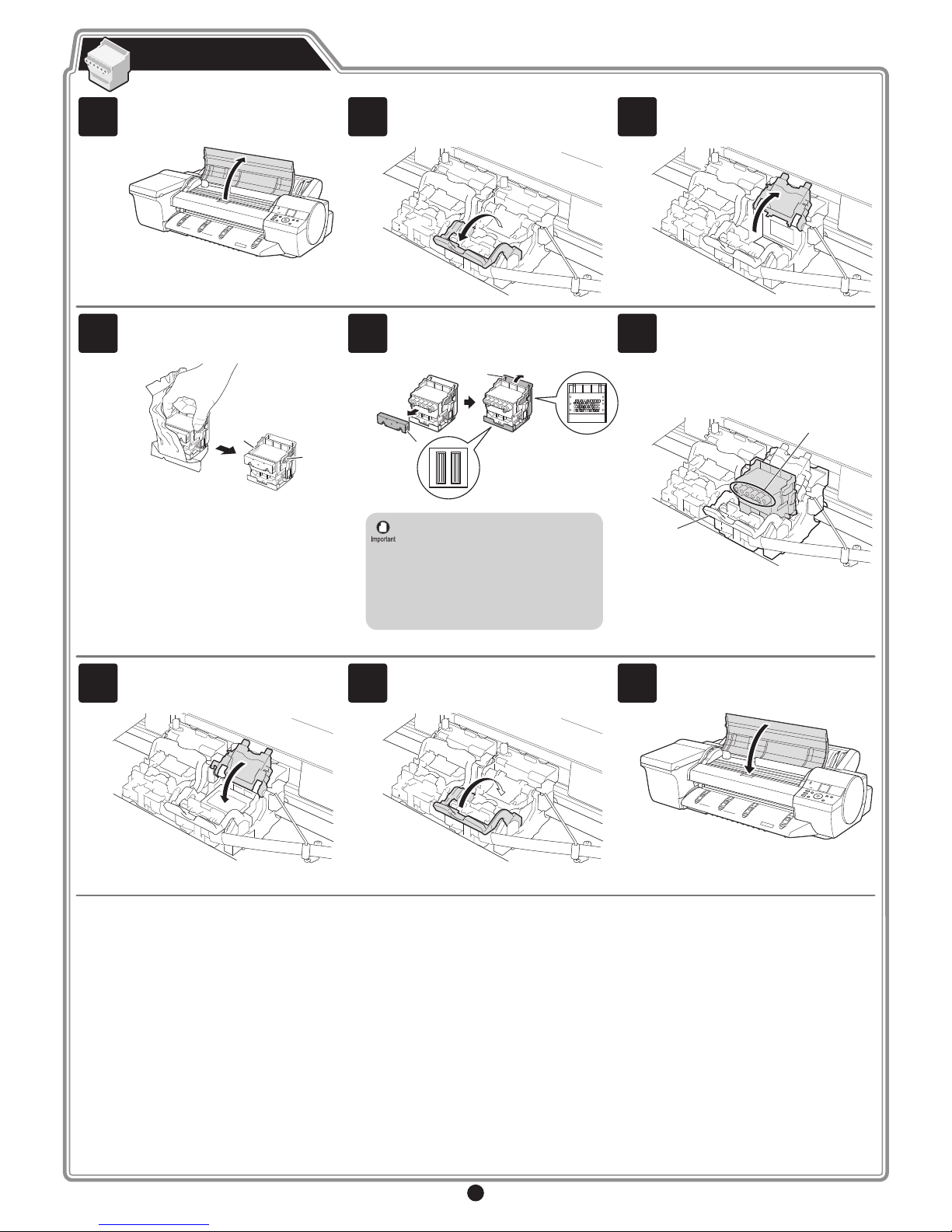
4
Install both printheads.
Install the Printheads
1
When the display screen shows Open
Upper Cover, open the top cover.
2
Pull the printhead fixer lever forward all
the way to open it completely.
3
Lift the printhead fixer cover to open it
fully.
4
Hold the printhead by the grips (a) as you
remove it from the pouch.
a
a
5
Remove the orange protective part (a). To
remove the other orange protective part
(b), push the grip (c) as you remove it.
a
b
c
• Never touch the parts covered by the
protective parts. Doing so may damage
the printhead and affect printing quality.
• The printhead contains ink, so be
careful not to spill it once the protective
parts are removed.
• Do not reattach the protective parts
after removing them. Dispose of these
materials according to local regulations.
.
6
Insert the printhead into the carriage (b)
with the ink holes (a) up and facing the
front of the printer as shown in the figure.
Carefully push the printhead firmly into
the carriage (b), ensuring that the parts
that were covered by the protective parts
do not touch the carriage (b).
b
a
7
Pull the printhead fixer cover down toward
the front to lock the printhead in place.
8
Press the printhead fixer lever inwards
until it clicks into place.
9
Repeat steps 2 to 8 to install the second
printhead set.
Close the top cover.
 Loading...