

Page 1
Adafruit Guide To Excellent Soldering
Created by Bill Earl
Last updated on 2014-06-28 08:30:54 PM EDT
Page 2

2
4
4
4
5
5
5
6
6
6
6
7
7
7
7
8
8
9
9
10
10
10
11
11
11
12
13
13
14
14
Guide Contents
Guide Contents
Tools
Building a Soldering Toolkit
Choosing a Soldering Iron
Basic Irons
Better Irons
Best Irons
Irons to avoid
For emergencies only:
Not for circuit board use:
Essential Tools and Supplies:
Stand
Solder
Diagonal Cutters
Other Handy Tools and Supplies
Vise
Third Hand
Solder Sucker
Solder Wick
Preparation
Heat the Iron
Clean the Iron
Tin the Tip
Make sure that the joint is clean
Immobilize the Joint
Steady the Board
Making a good solder joint
Heat the joint
Apply the solder
Let It Flow
© Adafruit Industries https://learn.adafruit.com/adafruit-guide-excellent-soldering Page 2 of 35
Page 3

14
14
15
16
17
17
17
18
18
18
18
20
20
21
22
24
25
27
28
28
29
30
31
32
33
34
34
35
Let It Cool
Trim the Lead
Congratulations!
Problems?
Surface Mount Components
Immobilize the Joint
Heat the Joint
Apply the Solder
Let it Flow
Let it Cool
Problems?
Common Soldering Problems
The Ideal Solder Joint
Disturbed Joint
Cold Joint
Overheated Joint
Insufficient Wetting (Pad)
Insufficient Wetting (Pin)
Insufficient Wetting
(Surface Mount)
Solder Starved
Too Much Solder
Untrimmed Leads
Solder Bridge
Lifted Pad
Repairing a Lifted Pad
Stray Solder Spatters
All of the Above!
© Adafruit Industries https://learn.adafruit.com/adafruit-guide-excellent-soldering Page 3 of 35
Page 4

Tools
Building a Soldering Toolkit
If you are just getting started in Electronics, Ladyada's Electronics
Toolkit (http://adafru.it/136) (pictured above) is a great kit full of quality tools - including
everything you need to make great solder joints. If you would rather build your toolkit pieceby-piece, read on:
Choosing a Soldering Iron
There are many types of soldering irons. For most Adafruit kits and projects, you will want a
pencil-style soldering iron with 25 watts or more.
An under-powered iron is a poor investment. It will end up costing you more in ruined kits
and damaged components.
It will take longer to heat the joint, allowing heat to spread to the component being
soldered - potentially overheating and damaging the component.
Longer heating times will also give more time for oxides to form on the surfaces being
soldered. This will prevent the solder from flowing and result in a poor joint.
Longer recovery times between joints can result in frustration, 'cold joints' or both.
You don't need to spend a fortune to get a good iron. Advanced features such as
temperature control and interchangeable tips are nice to have, but not essential for
hobbiest-level work.
© Adafruit Industries https://learn.adafruit.com/adafruit-guide-excellent-soldering Page 4 of 35
Page 5
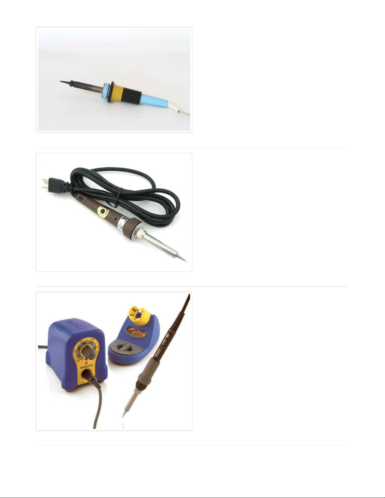
Basic Irons
There are many basic pencil style irons that are
suitable for hobbiest use. But you will need
one that is capable of heating the joints quickly
enough. Choose an iron with 25 watts at a
minimum.
Better Irons
An adjustable temperature iron with a little
more power will give you a bit more control and
allow you to work faster. The Adjustable 30W
110v Soldering Iron (http://adafru.it/180) in the
store is an excellent choice.
This iron is also available as part of Ladyada's
Electronics Toolkit (http://adafru.it/136), which
contains many other essential soldering tools.
Best Irons
A professional-style temperature-controlled
iron with interchangeable tips and 50 watts or
more of power is a joy to work with. Feedback
control keeps the tip temperature at precisely
the level you set. The extra watts speed
recovery time so that you can work faster.
Interchangeable tips let you select the ideal tip
shape for specialized work.
The 65 watt Hakko FX-
888 (http://adafru.it/303) is an
excellent professional quality soldering iron.
The Weller WES51 or WESD51 are also
excellent choices for serious electronics work.
© Adafruit Industries https://learn.adafruit.com/adafruit-guide-excellent-soldering Page 5 of 35
Page 6
Irons to avoid
In addition to underpowered irons, there are several types of irons to avoid for general
circuit-board work.
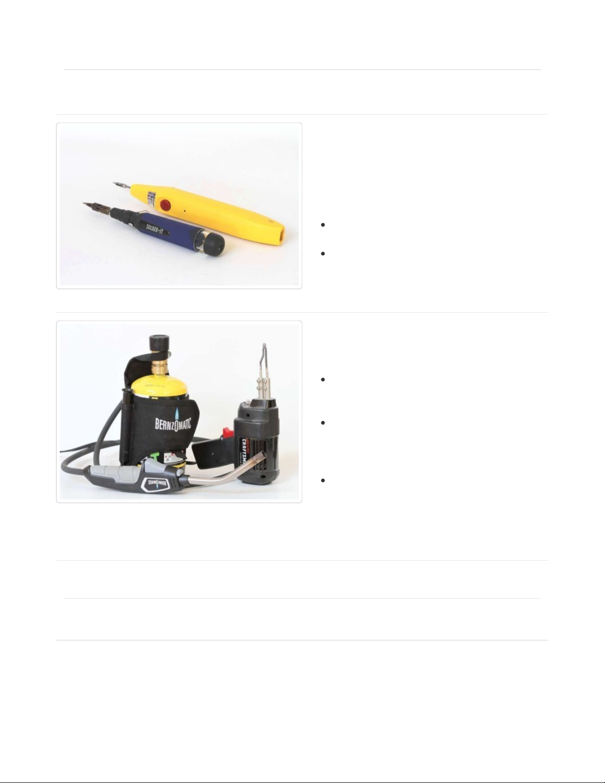
For emergencies only:
These irons are handy for occasions when you
have no place to plug in a regular soldering iron.
But they are not the best choice for a primary
soldering tool:
Butane Po wered Iro ns have plenty of
power but are difficult to control.
Battery Po wered Irons are generally
underpowered for most work.
Not for circuit board use:
These tools are not suitable for circuit board
work:
Torches of any kind are not suitable for
electronics work and will damage your
circuit boards.
Soldering Guns are OK for working with
heavy gauge wires, but don't have the
precision necessary for soldering
delicate electronics components.
Cold-Heat™ Irons inject current into the
joint to heat the tip. This current can be
damaging to sensitive electonic
components. Avoid these irons for
electronics work.
Essential Tools and Supplies:
These tools are the bare-minimum essentials required for soldering:
© Adafruit Industries https://learn.adafruit.com/adafruit-guide-excellent-soldering Page 6 of 35
Page 7

Stand
If your soldering iron does not have a built-in
stand, you will need a safe place to rest the hot
iron between uses. A Soldering Iron
Stand (http://adafru.it/150) will keep your iron
from rolling around and protect both you
and your work surface from burns.
Most stand holders come with a sponge and
tray for cleaning your soldering iron.
Solder
Standard 60/40 lead/tin Rosin
Core Solder (http://adafru.it/145) is the easiest
type to work with.
Diagonal Cutters
You will also need a pair of Diagonal
Cutters (http://adafru.it/152) for
trimming component leads after soldering.
Other Handy Tools and Supplies
© Adafruit Industries https://learn.adafruit.com/adafruit-guide-excellent-soldering Page 7 of 35
Page 8
These are some other tools and supplies you might find useful when working on soldering
projects.
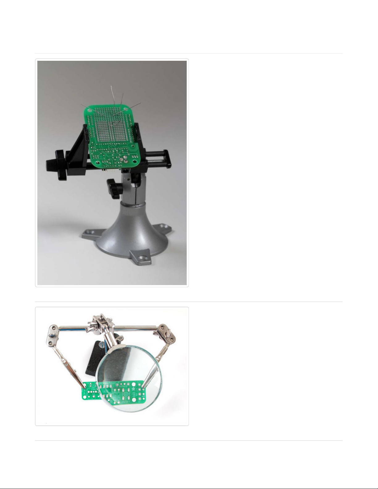
Vise
A vise holds your work steady as you solder.
This is important for both safety and sound
joints. The Panavise Jr (http://adafru.it/151) is
an ideal size for most Adafruit kits and
projects.
Third Hand
A Helping Third Hand (http://adafru.it/291) Tool
is a good for smaller boards, or to hold things in
place while terminating or splicing wires.
© Adafruit Industries https://learn.adafruit.com/adafruit-guide-excellent-soldering Page 8 of 35
Page 9
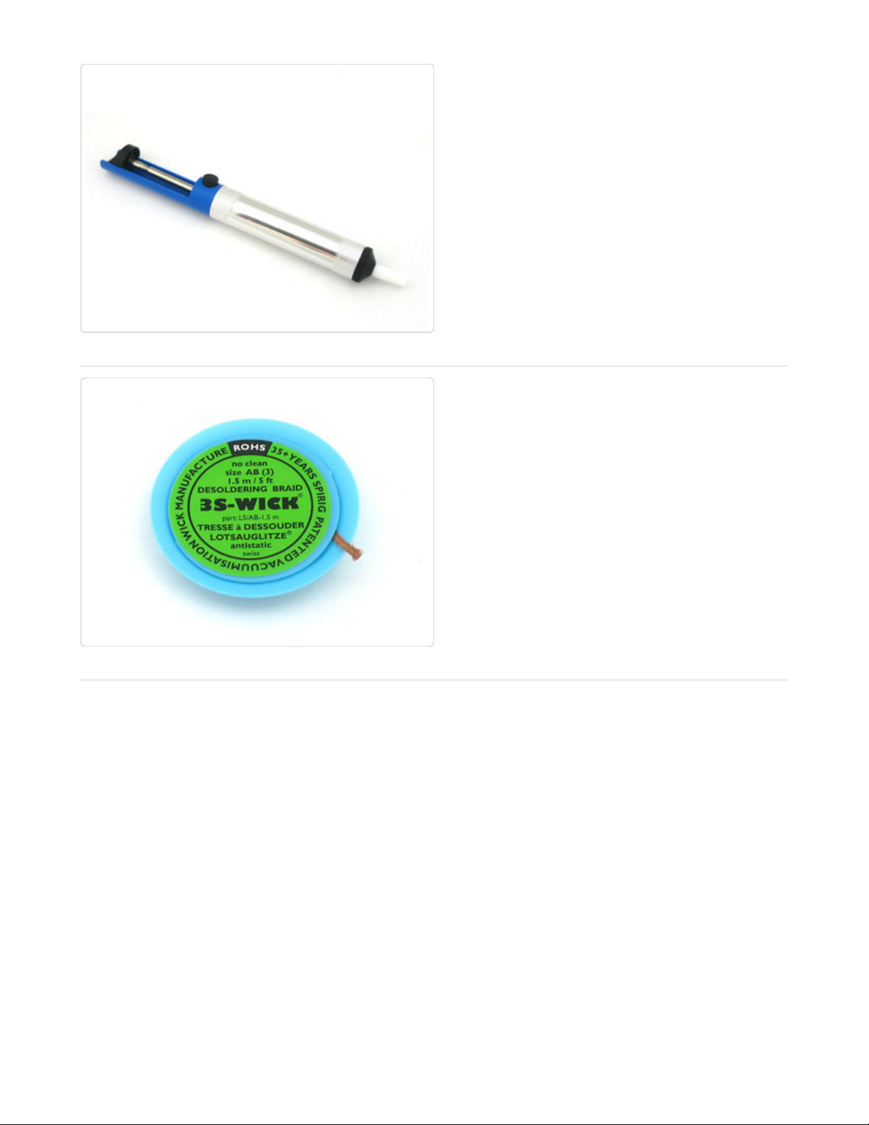
Solder Sucker
A Solder Sucker (http://adafru.it/148) is a very
helpful tools for removing excess solder
or when you need to de-solder a joint. As the
name implies, this device literally sucks the
solder out of the joint.
Solder Wick
Solder Wick (http://adafru.it/149) is another
way to clean excess solder from a joint. Unlike
the solder sucker, the wick soaks up the
molten solder.
© Adafruit Industries https://learn.adafruit.com/adafruit-guide-excellent-soldering Page 9 of 35
Page 10
Preparation
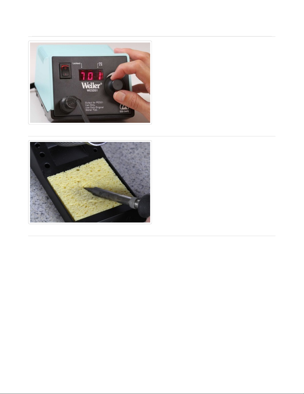
Heat the Iron
Plug an and/or turn on your soldering iron to
warm up. If you are using a temperature
controlled iron, set it to 700F/370C for 60/40 or
750F/400C for lead-free solder.
While the iron is heating dampen the sponge
with a little bit of water.
Clean the Iron
Wipe the tip of the hot iron on the damp
sponge to clean off any oxidation.
Do not use files or abrasives to clean the tip. It
will damage the plating and ruin the tip.
© Adafruit Industries https://learn.adafruit.com/adafruit-guide-excellent-soldering Page 10 of 35
Page 11
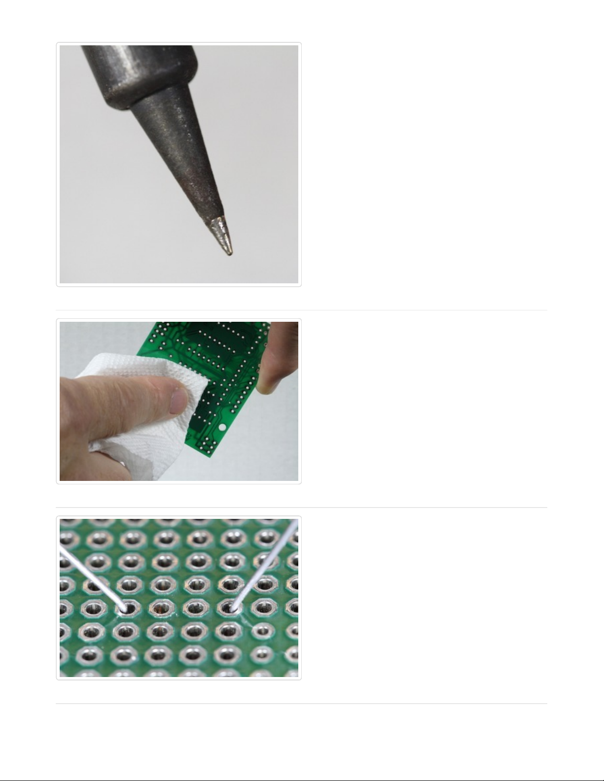
Tin the Tip
Apply a small amount of solder to the tip and
wipe again to tin the tip. You should have a
thin, shiny layer of molten solder on the tip of
your iron.
If the tip is badly oxidized and difficult to tin, it
can usually be reconditioned with some tiptinning paste.
Make sure that the joint is clean
Dirt, oxidation and oily fingerprints can prevent
the solder from wetting the solder-pad to
create a solid joint. All Adafruit boards are
plated to prevent oxidation, but if your
board appears dirty from storage or handling,
wipe it down with a little isopropyl alcohol.
Immobilize the Joint
This is very important! The parts being joined
must not move during the soldering process. If
there is any movement as the molten solder is
solidifying, you will end up with an unreliable
'cold joint'.
Most through-hole components can be
immobilized by simply bending the leads on the
solder-side of the hole.
© Adafruit Industries https://learn.adafruit.com/adafruit-guide-excellent-soldering Page 11 of 35
Page 12
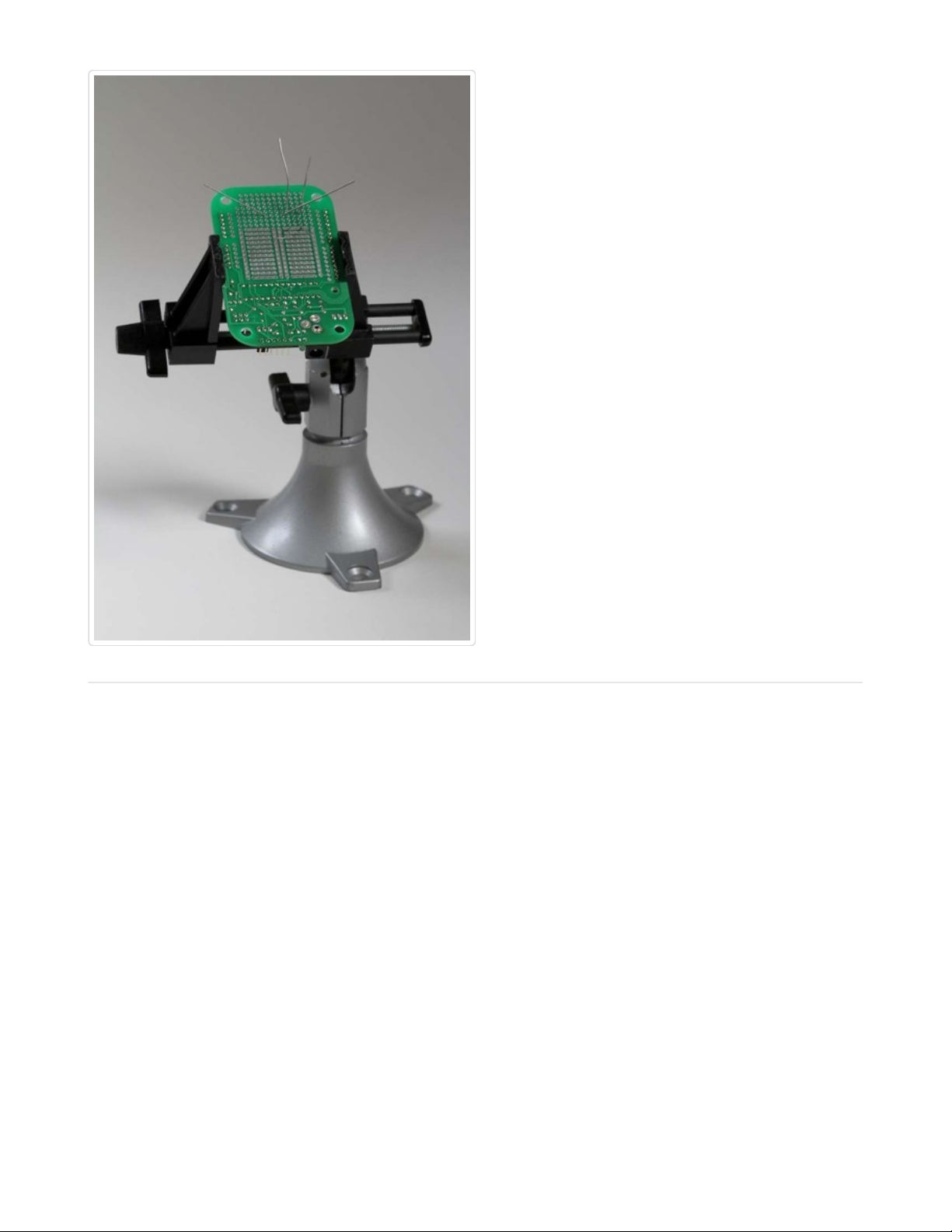
Steady the Board
A vise is a good way to keep the board from
moving around while you try to solder it.
Once the joint is clean and immobilized, you are
ready to apply the solder.
© Adafruit Industries https://learn.adafruit.com/adafruit-guide-excellent-soldering Page 12 of 35
Page 13
Making a good solder joint
Once you have prepared the your tools and the joint to be soldered, making a good solder
joint requires just a few simple steps.
Heat the joint
Heat the joint with the tip of the iron. Be sure to
heat both the solder pad and the component
lead or pin. A small drop of solder on the tip
will help to transfer the heat to the joint quickly.
© Adafruit Industries https://learn.adafruit.com/adafruit-guide-excellent-soldering Page 13 of 35
Page 14
Apply the solder
Touch the end of the solder to the joint so that
it contacts both the solder pad and the
component lead or pin. It should melt and flow
smoothly onto both the pin and the pad. If the
solder does not flow, heat the joint for another
second or two and try again.
Let It Flow
Keep heating the solder and allow it to flow into
the joint. It should fill the hole and flow
smoothly onto both the solder pad and the pin
or component lead.
Let It Cool
Once enough solder has been added to the
joint and it has flowed well onto both the
component lead and the solder pad, remove
the iron from the joint and allow it to cool
undisturbed.
Trim the Lead
Use your diagonal cutters to trim the lead close
to the board.
Note: This step applies only to components
with wire leads. It is not necessary to trim the
pins on Integrated circuit chips or sockets.
© Adafruit Industries https://learn.adafruit.com/adafruit-guide-excellent-soldering Page 14 of 35
Page 15

Congratulations!
Reward yourself with a Soldering
Badge (http://adafru.it/465).
© Adafruit Industries https://learn.adafruit.com/adafruit-guide-excellent-soldering Page 15 of 35
Page 16

Problems?
The last page of this guide illustrates a number of common soldering problems with advice
on prevention and repair.
© Adafruit Industries https://learn.adafruit.com/adafruit-guide-excellent-soldering Page 16 of 35
Page 17

Surface Mount Components
The previous page showed how to make a good through- hole joint. But more and more
components are only available in surface mount form these days. Not all surface mount
packages are easily worked by hand, but there are plenty that can be managed with the
same basic tools used for through-hole soldering.
Let's start with a surface-mount part common to several Adafruit kits: The SD Card Holder:
Immobilize the Joint
Unlike many surface mount components,
immobilizing the SD card holder is relatively
easy. There are small pegs on the back that fit
into positioning holes in the board. Once it is in
place, solder the four small corner tabs to
make it permanent.
Heat the Joint
Start by putting the tip of the hot iron on the
solder pad adjacent to the pin. The pad will
take longer to heat, so we apply most of the
heat to the pad to start.
© Adafruit Industries https://learn.adafruit.com/adafruit-guide-excellent-soldering Page 17 of 35
Page 18

Apply the Solder
When the joint is hot, apply solder to the side
opposite the iron. The solder should melt and
start to flow into the joint.
Let it Flow
Apply just enough solder to ensure a good
joint, then keep the heat on while the solder
wicks up between the pin and the pad to make
a good electrical bond.
Let it Cool
Remove the iron and allow the joint to cool
undisturbed.
Problems?
The last page of this guide illustrates a number of common soldering problems with advice
© Adafruit Industries https://learn.adafruit.com/adafruit-guide-excellent-soldering Page 18 of 35
Page 19

on prevention and repair.
© Adafruit Industries https://learn.adafruit.com/adafruit-guide-excellent-soldering Page 19 of 35
Page 20

Common Soldering Problems
The Ideal Solder Joint
The ideal solder joint for through-hole components should resemble the diagram below.
The photos that follow show some common soldering problems, with suggestions for repair
and prevention:
© Adafruit Industries https://learn.adafruit.com/adafruit-guide-excellent-soldering Page 20 of 35
Page 21

Disturbed Joint
A Disturbed joint is one that has been
subjected to movement as the solder was
solidifying. The surface of the joint may appear
frosted, crystalline or rough.
Often called a 'Cold Joint'. They can look similar
to a true cold joint, but the cause is different.
Repair: This joint can be repaired by
reheating and allowing it to cool undisturbed.
Prevention: Proper preparation, including
immobilizing the joint and stabilizing the work in
a vise can prevent disturbed joints.
© Adafruit Industries https://learn.adafruit.com/adafruit-guide-excellent-soldering Page 21 of 35
Page 22

Cold Joint
A 'Cold Joint' is one where the solder did not
melt completely. It is often characterized by a
rough or lumpy surface. Cold joints are
unreliable. The solder bond will be poor and the
cracks may develop in the joint over time.
Repair: Cold joints can usually be repaired by
simply re-heating the joint with a hot iron until
the solder flows. Many cold joints (such as the
one pictured) also suffer from too much solder.
The excess solder can usually be drawn-off
with the tip of the iron.
Prevention: A properly pre-heated soldering
iron with sufficient power will help prevent cold
joints.
© Adafruit Industries https://learn.adafruit.com/adafruit-guide-excellent-soldering Page 22 of 35
Page 23

© Adafruit Industries https://learn.adafruit.com/adafruit-guide-excellent-soldering Page 23 of 35
Page 24

Overheated Joint
At the other extreme, we have the overheated
joint. The solder has not yet flowed well and
the residue of burnt flux will make fixing this
joint difficult.
Repair: An overheated joint can usually be
repaired after cleaning. Careful scraping with
the tip of a knife, or little isopropyl alcohol & a
toothbrush will remove the burnt flux.
Prevention: A clean, hot soldering iron,
proper preparation and cleaning of the joint will
help prevent overheated joints.
© Adafruit Industries https://learn.adafruit.com/adafruit-guide-excellent-soldering Page 24 of 35
Page 25

Insufficient Wetting (Pad)
These two joints both show signs of insufficient
wetting of the solder pad. The solder has
wetted the leads nicely, but it has not formed a
good bond with the pad. This can be caused by
a dirty circuit board, or by failing to apply heat
to the pad as well as the pin.
Repair: This condition can usually be repaired
by placing the tip of the hot iron at the base of
the joint until the solder flows to cover the pad.
Prevention: Cleaning the board and even
heating of both the pad and the pin will prevent
this problem.
© Adafruit Industries https://learn.adafruit.com/adafruit-guide-excellent-soldering Page 25 of 35
Page 26

© Adafruit Industries https://learn.adafruit.com/adafruit-guide-excellent-soldering Page 26 of 35
Page 27

Insufficient Wetting (Pin)
This solder in this joint has not wetted the pin at
all and has only partially wetted the pad. In this
case, heat was not applied to the pin and the
solder was not given adequate time to flow.
Repair: This joint can be repaired by reheating and applying more solder. Be sure that
the tip of the hot iron is touching both the pin
and the pad.
Prevention: Even heating of both the pin and
the pad will prevent this problem.
© Adafruit Industries https://learn.adafruit.com/adafruit-guide-excellent-soldering Page 27 of 35
Page 28
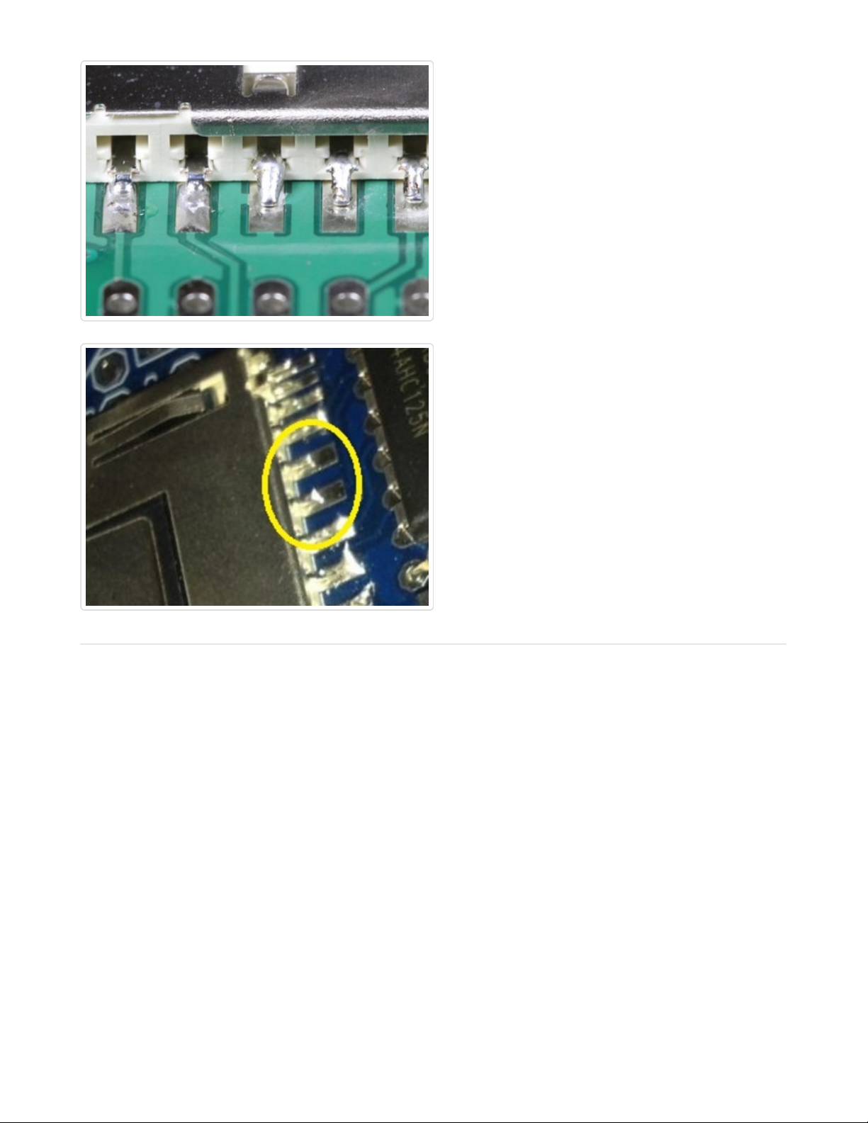
Insufficient Wetting
(Surface Mount)
Here we have three pins of a surface mount
component where the solder has not flowed
onto the solder pad. This is caused by heating
the pin instead of the pad.
Repair: This is easily repaired by heating the
solder pad with the tip of the iron, then applying
solder until it flows and melts together with the
solder already on the pin.
Prevention: Heat the pad first.
© Adafruit Industries https://learn.adafruit.com/adafruit-guide-excellent-soldering Page 28 of 35
Page 29

Solder Starved
A solder starved joint simply does not have
enough solder. It may make good electrical
contact, but it is hard to verify by inspection. In
any case, it is not a strong joint and may
develop stress cracks and fail over time.
Repair: Re-heat the joint and add more solder
to make a good strong joint.
© Adafruit Industries https://learn.adafruit.com/adafruit-guide-excellent-soldering Page 29 of 35
Page 30

Too Much Solder
This might be a perfectly good joint, but we
can't tell for sure. It is entirely possible that this
blob of solder wets neither the pin nor the pad
and is not a reliable electrical connection. The
best evidence of proper wetting (and good
electrical contact) is a nice concave surface as
on the joint on the far left.
Repair: It is usually possible to draw off some
of the excess solder with the tip of a hot iron. In
extreme cases, a solder-sucker or some
solder wick can be helpful as well.
© Adafruit Industries https://learn.adafruit.com/adafruit-guide-excellent-soldering Page 30 of 35
Page 31

Untrimmed Leads
Leads that are too long are potential short
circuits. The two joints on the left are an
obvious danger of touching. But the one on the
right is long enough to be dangerous as well. It
would not take much force to bend that lead
over to touch an adjacent trace.
Repair: Trim all leads just at the top of the
solder joint.
© Adafruit Industries https://learn.adafruit.com/adafruit-guide-excellent-soldering Page 31 of 35
Page 32

Solder Bridge
The left two solder joints have melted
together, forming an unintended connection
between the two.
Repair: Sometimes the excess solder can be
drawn off by dragging the tip of a hot iron
between the two solder joints. If there is too
much solder, a solder sucker or solder wick can
help get rid of the excess.
Prevention: Solder bridges most often
happen between joints with too much solder to
begin with. Use only enough solder to make a
good joint.
© Adafruit Industries https://learn.adafruit.com/adafruit-guide-excellent-soldering Page 32 of 35
Page 33

Lifted Pad
This photo shows a solder pad that has
become detached from the surface of the
circuit board. This most often occurs when
trying to de-solder components from the
board. But it can result simply from overworking
the joint to the point where the adhesive bond
between copper and the board is destroyed.
Lifted pads are especially common on boards
with thin copper layers and/or no throughplating on the holes.
© Adafruit Industries https://learn.adafruit.com/adafruit-guide-excellent-soldering Page 33 of 35
Page 34

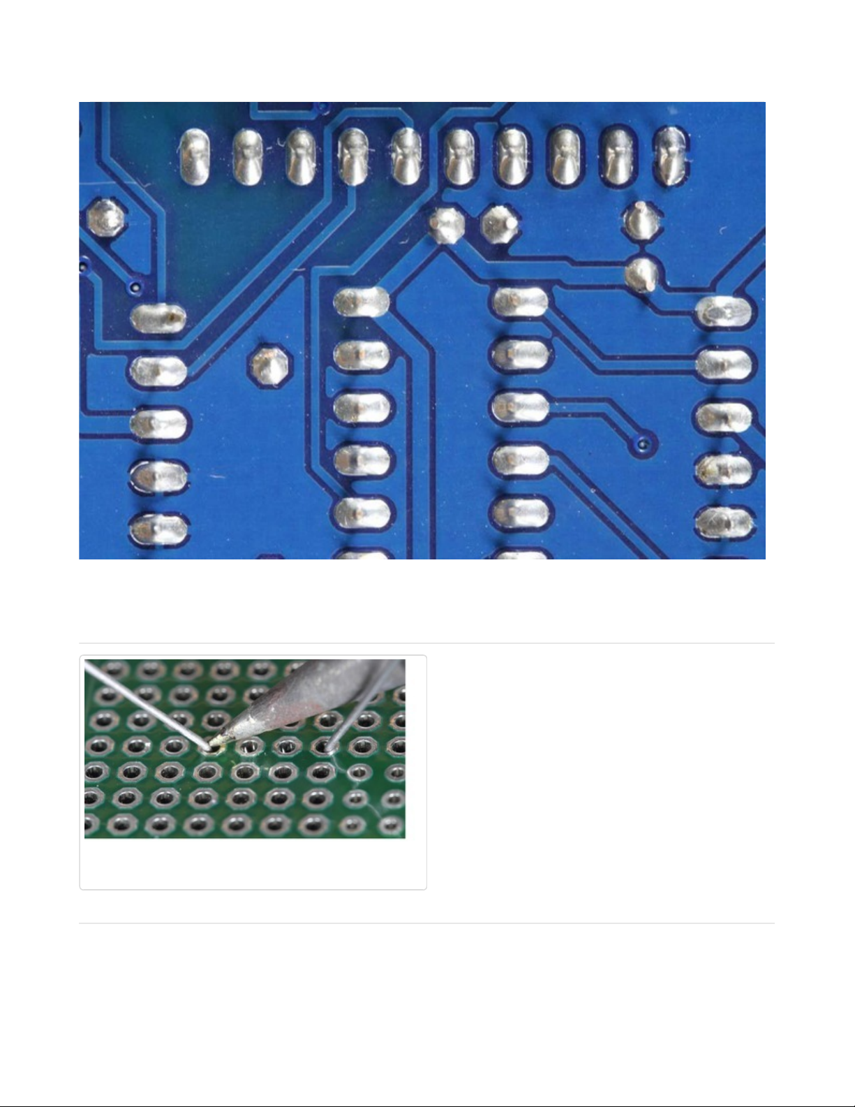
Repairing a Lifted Pad
It may not be pretty, but a lifted pad can usually
be repaired. The simplest repair is to fold the
lead over to a still-attached copper trace and
solder it as shown to the left. If your board has
a solder-mask, you will need to carefully scrape
off enough to expose the bare copper.
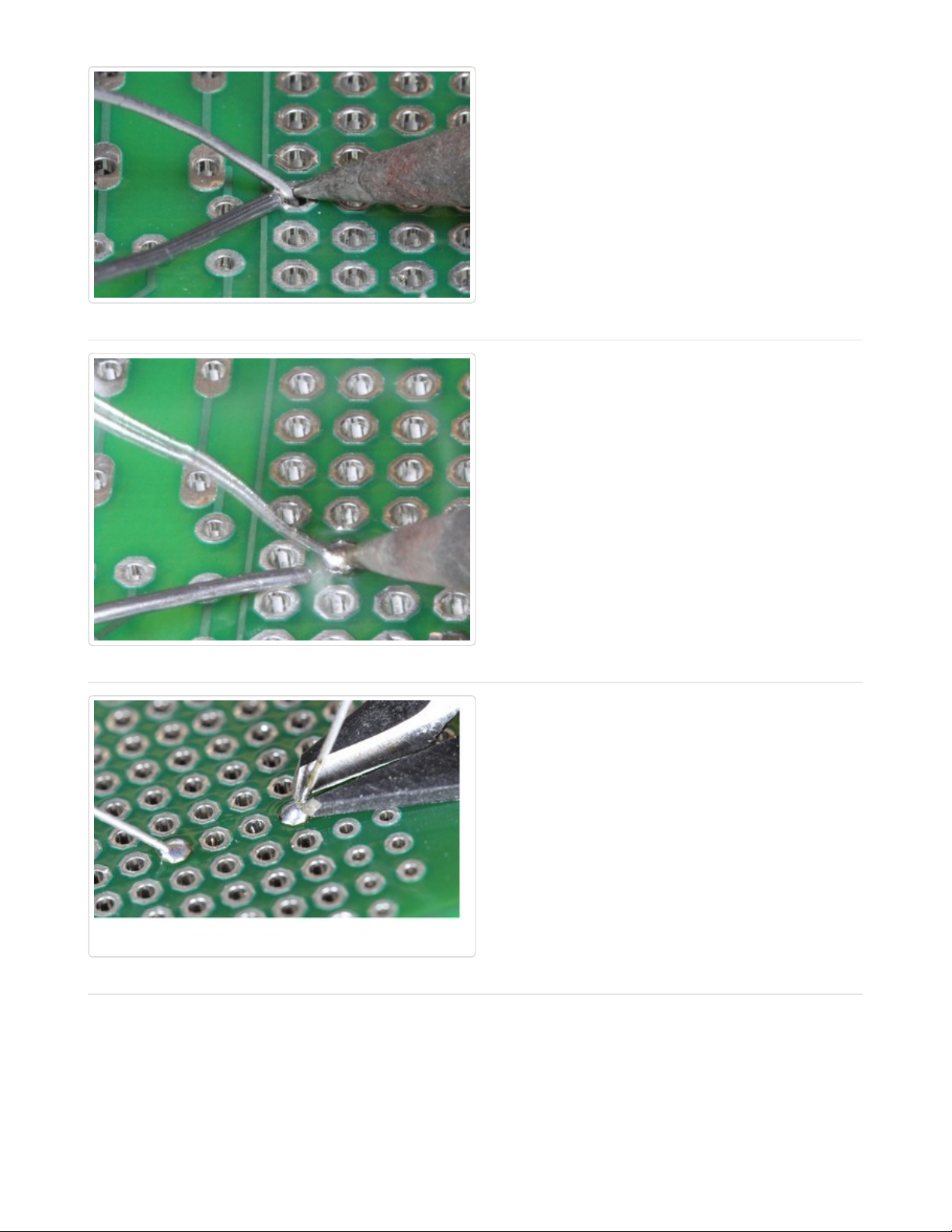
Other alternatives are to follow the trace to the
next via and run a jumper to there. Or, in the
worst case, follow the trace to the nearest
component and solder your jumper to the leg
of that. Not exactly pretty, but functional.
Stray Solder Spatters
These bits of solder are held to the board only
by sticky flux residue. If they work loose, they
can easily cause a short circuit on the board.
Repair: These are easy to remove with the tip
of a knife or tweezers.
© Adafruit Industries https://learn.adafruit.com/adafruit-guide-excellent-soldering Page 34 of 35
Page 35

All of the Above!
Don't panic. Take your time. Most joints can be
repaired with patience. If the solder refuses to
flow the way you want it to:
1. Stop and let the joint cool.
2. Clean and tin your iron.
3. Clean off any burnt flux from the joint.
4. Let the iron come back up to
temperature.
5. Then reheat the joint and try again.
© Adafruit Industries Last Updated: 2014-06-28 08:30:56 PM EDT Page 35 of 35
 Loading...