

Canon BJ-W3000, BJ-W3050 Service Manual
QY8-1366-000
REVISION 0
COPYRIGHT 2000 CANON INC. CANON BJ-W3000/3050 0100 GR 0.40-0 PRINTED IN JAPAN (IMPRIME AU JAPON)
JAN. 2000

0000 GR 0.40-0

Target Readers
This manual is published by Canon Inc. for qualified persons and contains the necessary technical
information for technical theory, installation, maintenance, and repair of products. This manual covers
all localities where the products are sold. For this reason, it may contain information that does not
apply to your locality.
Revisions
This manual may include technical inaccuracies or typographical errors due to improvements or
changes in the products. When amendments are made to the content of this manual, Canon will issue
technical information as the need arises. In the event of major alterations to the content of this manual
over a long or short period, Canon will publish a revised version of the manual.
The following paragraphs do not apply to any countries where such provisions are
inconsistent with local law.
Trademarks
The product names and company names appearing in this manual are the registered trademarks or
trademarks of the individual companies.
Copyright
This manual is copyrighted and all rights reserved. Under the copyright laws, this manual may not be
copied, reproduced, or translated into other languages, in whole or in part, without the express written
consent of Canon Inc. except in the case of internal business use.
Copyright 2000 by Canon Inc.
CANON INC.
Quality Engineering Center
30-2 Shimomaruko 3-chome, Ohta-ku, Tokyo 146-8501, Japan
This manual was produced on an Apple®Power Macintosh®G3 personal computer and Canon LASER
SHOT LBP-730PS laser beam printer; final pages were printed on Varityper
®
4300J.
All logos graphics were produced with Adobe
®
Illustrator®5.0J / 5.5J / 8.0J and MACROMEDIA
FREEHAND 7.0J.
All documents and all page layouts were created with Adobe
®
Page Maker®6.5J and QuarkXPress 3.3J.

PREFACE
This Service Manual describes fundamental field service for the BJ-W3000/BJ-W3050 large
format printer.
This Manual is composed of the following chapters:
Chapter 1 General Description: Features, specifications and operating procedures
Chapter 2 Basic Operation: Operation of mechanical and electric functions
Chapter 3 Mechanical System: Mechanical setup and assembling/disassembling procedure
Chapter 4 Maintenance and Servicing: Periodic parts replacement, Standard service life of
consumables, Periodical services, points of maintenance and inspections
Chapter 5 Troubleshooting: Service mode, adjusting and settings, operation trouble
correction, image trouble correction
Chapter 6 Circuite diagrams
Appendix Menu guide
i
ii
PREFACE
Descriptions in this manual are based on the following conventions.
1. In the Basic Operation section, the roles of each function, relationships between electrical
and mechanical systems, and the timing for each part are summarized.
The mark indicates mechanical drive transmission. The mark
accompanying a signal name indicates the flow of electrical signals.
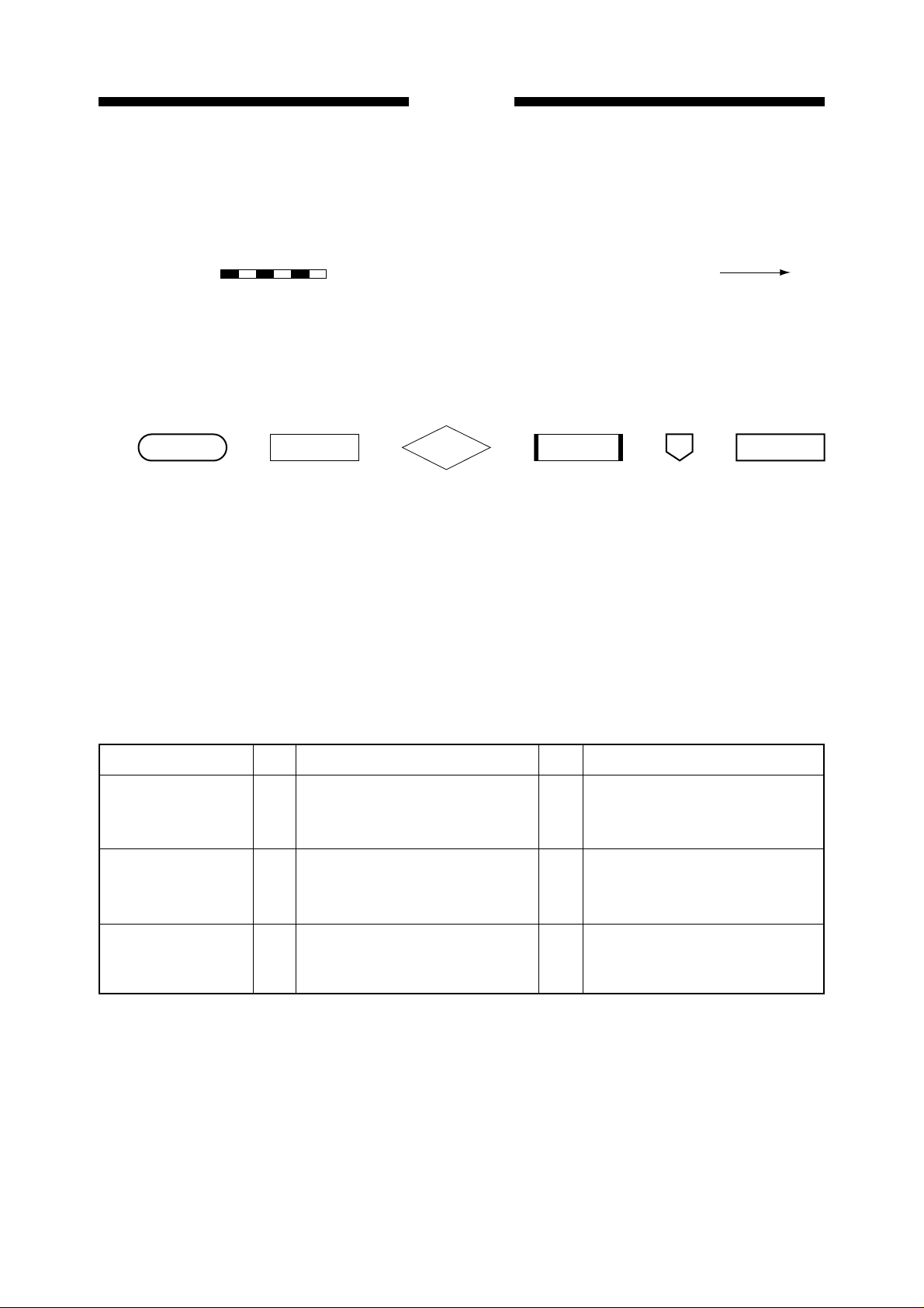
Flow charts are also used in the summary of operation.
The symbols used in the flow charts are as follows:
Start/completion Operation Decision Remedy Jump Stop
2. In the descriptions of digital circuits, "1" or "H" indicates a high voltage level, and "0" or
"L", a low voltage level. However, the actual voltage values vary depending on the circuit.
3. It is assumed that the Printed circuit board (PCB) will not be repaired by the user. There-
fore, the descriptions of the circuits on the PCB are limited to block diagrams.
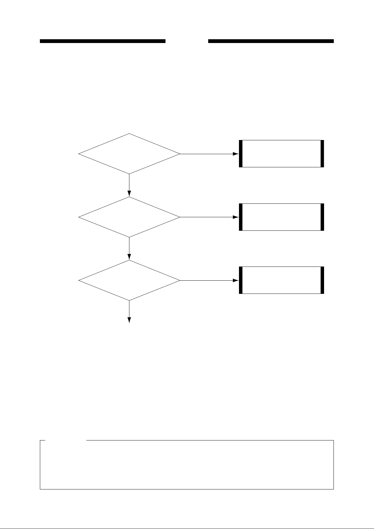
4. Troubleshooting is described using procedural tables.
The procedural table is a variation of a general flow chart.
An example is shown below.
e.g. No power is supplied.
Cause Result
Unplugged power
source
Power source failure
Blown fuse
Step RemedyCheck item
1
Is the power cord properly connected to the receptacle on the
machine and the outlet?
Is the specified voltage applied to
2
the outlet?
Is the fuse on the DC power PCB
3
(F1) blown?
NO
Connect the power code to the
machine and outlet.
Explain to the customer that the
NO
trouble is not attributable to the
machine.
Remove the cause of the blown
YES
fuse and replace the DC power
PCB.
• If you want to know the possible causes of any specific problem (suspected parts), refer to
the "Cause" column in the table.
In the event "No power is supplied" as shown in the above table, an unplugged power
source, power source failure, blown fuse, and other causes can be considered.
iii
ii
PREFACE
• In order to remedy a problem, check the Steps in order. Answer the first "Check item"
question. If your answer matches that given in the "Result", follow the corresponding procedure in the "Remedy" column. If your answer is not the same, go on to the next step and
repeat the same procedure.
<Remedy><Check item> <Result><Step>
Is the
power cord properly
1
connected to the receptacle
on the machine
and outlet?
YES
NO
Connect in the power code
to the machine and outlet.
Is the specified
2
3
voltage applied to the outlet?
YES
Is the fuse
on the DC power PCB (F1)
blown?
NO
NO
YES
Explain to the customer that
the trouble is not attributable
to the machine.
Remove the cause of the
blown fuse and replace the
DC power PCB.
• When checking voltages using a tester is required, it will be specified in the check item.
For instance; "measure the voltage between J102-1 (+) and JI02-2 (-) on the engine controller PCB". In this case, apply the plus and minus leads of the tester to the (+) and (-) terminals indicated after the connector numbers:
e.g. JI02-1 (+): Plus lead
JI02-2 (-): Minus lead
5. The signal address of the circuit diagram is shown by applicable pages of each controller
(indicated at the upper right of the circuit diagram) and its location.
CAUTION
When checking voltages with a tester, touching the components or connector terminals on
the PCB with the hands may cause an electric shock. It is advisable to wear rubber gloves
or the like when power is supplied to the machine to protect yourself from electric shock.
iii
iv

PREFACE
CONTENTS
CHAPTER 1 GENERAL DESCRIPTION
I. SPECIFICATIONS ............................................ 1-1
1. Type............................................................. 1-1
2. Exterior ........................................................ 1-1
3. Mechanism .................................................. 1-2
4. Media ........................................................... 1-4
5. Others .......................................................... 1-6
II. NAMES OF COMPONENTS............................. 1-7
A. External View............................................... 1-7
B. Carriage ....................................................... 1-8
C. Cable Connections ...................................... 1-8
D. Rear Side of Main Unit................................. 1-9
E. Printing Direction.......................................... 1-9
III. OPERATION ................................................... 1-10
A. Operation Panel......................................... 1-10
B. Printer States ............................................. 1-11
C. User Mode Menu .......................................... 13
1. Menu guide ............................................. 13
2. Menu and parameter setup.................. 1-14
3. Details of user mode menus ................ 1-14
4. Using the setup list............................... 1-25
5. Dump mode.......................................... 1-27
6. Image layout......................................... 1-27
D. Basic Operation ......................................... 1-29
E. Paper Thickness Adjustment Lever ........... 1-31
IV. CARTRIDGE REPLACEMENT ....................... 1-32
A. Replacing the BJ Print head ....................... 1-32
B. Replacing the Ink Tank ............................... 1-34
V. SIMM REPLACEMENT ................................... 1-36
A. About SIMM ............................................... 1-36
B. SIMM Installation ....................................... 1-36
C. SIMM Removal .......................................... 1-37
VI. CAUTIONS ON HANDLING ............................ 1-38
A. Cartridges .................................................. 1-38
1. Cautions on handling the BJ print
head ..................................................... 1-38
2. Cautions on handling ink tanks ............ 1-38
B. Paper Storage Environment ...................... 1-39
C. Paper ......................................................... 1-39
D. After Printing.............................................. 1-39
VII. USER MAINTENANCE................................... 1-40
A. Head Cleaning ........................................... 1-40
B. Normal Cleaning ......................................... 1-40
VIII. INSTALLATION ENVIRONMENT................. 1-41
IX. PACKAGE CONFIGURATION ....................... 1-42
X. TRANSPORTING THE PRINTER ................... 1-43
CHAPTER 2 BASIC OPERATION
I. BASIC OPERATION ......................................... 2-1
A. Functional Configuration.............................. 2-1
B. Interface Input/Output .................................. 2-2
1. Parallel interface ..................................... 2-2
2. Serial interface........................................ 2-6
C. Image Controller .......................................... 2-7
D. Engine Controller ....................................... 2-10
E. Engine controller Input/Output ................... 2-12
1. Engine controller input/output (1/3)...... 2-12
2. Engine controller input/output (2/3)...... 2-13
3. Engine controller input/output (3/3)...... 2-14
F. Summary of Operation............................... 2-15
1. When the power switch is turned ON... 2-15
2. When media is loaded.......................... 2-17
3. Printing ................................................. 2-18
II. CARRIAGE UNIT ............................................ 2-22
A. Outline ....................................................... 2-22
B. Carriage Motor Control .............................. 2-24
1. Outline.................................................. 2-24
2. Operation ............................................. 2-24
3. Detection of front cover open/closed ... 2-25
C. Linear Encoder .......................................... 2-26
1. Outline.................................................. 2-26
2. Structure............................................... 2-26
3. Output signal........................................ 2-26
4. Control.................................................. 2-27
D. Media Sensor............................................. 2-28
1. Outline.................................................. 2-28
2. Paper width detection........................... 2-28
3. Skew detection..................................... 2-29
4. Light compensation.............................. 2-31
5. Auto band adjustment .......................... 2-31
6. Automatic print position adjustment ..... 2-32
E. Detection of the Ink Tank........................... 2-34
1. Outline.................................................. 2-34
2. Method of detecting the ink tank .......... 2-34
iv
v

PREFACE
F. Remaining Ink Detection............................ 2-35
1. Outline.................................................. 2-35
2. Method of detecting remaining ink ....... 2-36
G. Cutter Unit.................................................. 2-38
1. Outline.................................................. 2-38
2. Cutting operation.................................. 2-38
III. BJ CARTRIDGE .............................................. 2-39
A. BJ Cartridge............................................... 2-39
1. Overview .............................................. 2-39
2. Structure............................................... 2-39
3. BJ print head........................................ 2-41
4. Nozzle arrangement............................. 2-42
B. BJ Print head Drive.................................... 2-43
1. Construction of electric head unit......... 2-43
2. Print signal ........................................... 2-45
IV. PURGE UNIT .................................................. 2-46
A. Outline ....................................................... 2-46
B. Capping Function....................................... 2-51
1. Outline.................................................. 2-51
2. Operation ............................................. 2-51
C. Head Cleaning........................................... 2-52
1. Outline.................................................. 2-52
2. Wiping .................................................. 2-52
3. Maintenance jet.................................... 2-53
4. Suction ................................................. 2-54
D. Waste Ink Absorber Unit............................ 2-56
1. Waste ink absorber unit ....................... 2-56
V. FEEDER UNIT ................................................ 2-57
A. Outline ....................................................... 2-57
B. Paper Feed Motor Control ......................... 2-58
1. Outline.................................................. 2-58
2. Operation ............................................. 2-58
C. Feeding Operation..................................... 2-60
1. Outline.................................................. 2-60
2. Loading paper ...................................... 2-60
3. Paper feeding during printing............... 2-61
4. Feeding operation ................................ 2-62
5. PE sensor............................................. 2-62
VI. FAN.................................................................. 2-63
VII. POWER SUPPLY ........................................... 2-65
A. Power Supply Outline ................................ 2-65
B. Power Circuit ............................................. 2-66
1. AC power supply.................................. 2-66
2. DC power supply.................................. 2-66
C. Power Circuit Protection ............................ 2-66
CHAPTER 3 MECHANICAL SYSTEM
DISASSEMBLY AND ASSEMBLY.......................... 3-1
1. List of Main Parts ......................................... 3-2
2. Outline of disassembly and assembly of
main parts .................................................... 3-3
PRECAUTIONS FOR DISASSEMBLY
AND REASSEMBLY .............................................. 3-5
I. EXTERNALS ..................................................... 3-7
A. External Cover ............................................. 3-7
1. Removing the right cover ....................... 3-7
2. Removing the upper cover and
front cover .............................................. 3-7
3. Removing the lower cover...................... 3-8
4. Removing the front cover switch............ 3-9
B. Operation Panel........................................... 3-9
1. Removing the operation panel ............... 3-9
C. Fan............................................................. 3-10
1. Removing the cooling fan..................... 3-10
2. Removing the suction fan..................... 3-12
II. CARRIAGE UNIT ............................................ 3-13
1. Removing the carriage unit .................. 3-13
2. Removing the carriage belt .................. 3-15
3. Installing the carriage belt .................... 3-16
4. Removing the linear scale.................... 3-17
5. Replacing the flexible cable ................. 3-18
III. PURGE UNIT .................................................. 3-21
1. Removing the purge unit...................... 3-21
2. Removing the waste ink absorber
unit ....................................................... 3-23
IV. FEEDER UNIT ................................................ 3-24
1. Removing the pinch roller unit.............. 3-24
2. Removing the platen ............................ 3-25
3. Installing the platen .............................. 3-26
4. Removing the paper feed roller............ 3-27
5. Removing the PE sensor ..................... 3-27
V. DRIVING UNIT ................................................ 3-28
1. Removing the carriage motor............... 3-28
2. Removing the paper feed motor .......... 3-29
3. Installing the paper feed motor ............ 3-30
4. Fastening the paper feed roller set
screws .................................................. 3-30
VI. ELECTRICAL PART........................................ 3-32
1. Removing the image controller ............ 3-32
2. Removing the engine controller ........... 3-33
3. Removing the PCB box........................ 3-34
4. Removing the power switch ................. 3-35
5. Removing the DC power supply........... 3-35
v
vi

PREFACE
CHAPTER 4 MAINTENANCE AND SERVICING
I. PERIODIC PARTS REPLACEMENT ................ 4-1
II. STANDARD SERVICE LIFE OF
CONSUMABLES............................................... 4-1
III. PERIODIC SERVICE ........................................ 4-1
CHAPTER 5 TROUBLESHOOTING
I. SERVICE MODE ............................................... 5-1
A. Outline.......................................................... 5-1
B. Service Mode Operation .............................. 5-1
1. How to enter the service mode .............. 5-1
2. Stopping the service mode .................... 5-1
C. Service Mode Map....................................... 5-2
D. Service Mode............................................... 5-3
1. Control display mode ............................. 5-3
2. Adjusting mode ...................................... 5-5
3. Operation/inspection mode .................... 5-6
4. Counter mode ........................................ 5-7
5. Initialization mode .................................. 5-8
II. ADJUSTMENTS AND SETTINGS .................... 5-9
A. About Adjustments and Settings.................. 5-9
B. Items for Adjustment and Setting................. 5-9
C. Adjustment and Setting Procedures ........... 5-10
1. Automatic printing position adjustment
and automatic band adjustment
(User-settable) ..................................... 5-11
2. Waste ink counter reset (for exclusive
use in service mode) ............................ 5-11
3. Replacing the image controller and
engine controller................................... 5-11
4. Paper feed accuracy compensation
value adjustment .................................. 5-13
5. Changing the parallel interface
communication mode ........................... 5-15
6. Image controller/engine controller
upgrade procedure............................... 5-16
III. ERROR/WARNING CODES ........................... 5-18
A. Outline ....................................................... 5-18
B. List of Error and Warning Codes ............... 5-18
1. 001xx (Media/feeding system) ............. 5-20
2. 003xx (Drive system) ........................... 5-22
3. 004xx (BJ Print head system) .............. 5-23
4. 005xx (Ink tank system) ....................... 5-24
5. 007xx (Purge system) .......................... 5-24
6. 008xx (Cutter system) .......................... 5-25
7. 011xx (Engine controller) ..................... 5-25
8. 012xx
9. 015xx (Power supply related)............... 5-26
(Internal communication system) ....
5-26
IV. MAINTENANCE AND INSPECTION................ 4-2
A. Cleaning/Inspection Points .......................... 4-2
B. Lubrication Points ........................................ 4-3
10.021xx (User-adjusted system) ............. 5-26
11.051xx (Image controller) ...................... 5-27
12.052xx (Serial interface communication
system)................................................. 5-27
13.053xx (Parallel interface communication
system)................................................. 5-27
14.060xx (Internal data processing
system)................................................. 5-28
15.061xx (GL command system) .............. 5-29
16.062xx (GL2 command system) ............ 5-29
17.063xx (RTL command system) ............ 5-29
18.064xx (ESC command system)............ 5-30
19.065xx (PJL command system)............. 5-30
20.067xx (TIFF command system) ........... 5-30
21.097xx (Direct error code from the image
controller) ............................................. 5-31
22.098xx (Direct error code from the engine
controller) ............................................. 5-31
23.099xx (Others) ..................................... 5-31
IV. CORRECTION OF OPERATION DEFECTS .. 5-32
1. 001xx (Media/feeding system) ............. 5-32
2. 003xx (Drive system) ........................... 5-33
3. 004xx (BJ Print head system) .............. 5-34
4. 005xx (Ink tank system) ....................... 5-34
5. 007xx (Purge unit)................................ 5-35
6. 008xx (Cutter system).......................... 5-36
7. 011xx (Engine controller) ..................... 5-36
8. 012xx
9. 015xx (Power supply related)............... 5-37
10.021xx (User-adjusted system) ............. 5-37
11.051xx (Image controller) ...................... 5-37
12.052xx (Serial interface communication
13.053xx (Parallel interface communication
14.060xx (Internal data processing
15.061xx (GL command system) .............. 5-39
16.062xx (GL2 command system) ............ 5-39
17.063xx (RTL command system) ............ 5-39
18. 064xx (ESC command system) ........... 5-39
(Internal communication system) ....
system)................................................. 5-38
system)................................................. 5-38
system)................................................. 5-38
5-37
vi
vii

PREFACE
19.065xx (PJL command system)............. 5-39
20.067xx (TIFF command system) ........... 5-39
21.097xx (Direct error code from the image
controller) ............................................. 5-39
22.098xx (Direct error code from the engine
controller) ............................................. 5-39
23.099xx (Others) ..................................... 5-39
24. No power ............................................ 5-40
25.Nothing is indicated on the operation
panel .................................................... 5-41
26.Opening and closing of front cover is
not detected ......................................... 5-41
27.Wiper solenoid does not working ......... 5-41
28.Media is not fed.................................... 5-42
29.Suction fan does not rotate .................. 5-42
V. CORRECTION OF IMAGE DEFECTS............ 5-43
A. Initial Inspection ......................................... 5-43
1. Installation environment ....................... 5-43
2. Media check......................................... 5-43
B. Corrective Procedures for Image Defects.. 5-44
CHAPTER 6 CIRCUIT DIAGRAM
1. Non-ejection of ink ............................... 5-44
2. Vertical misalignment 1........................ 5-45
3. Vertical misalignment 2........................ 5-46
4. Low resolution...................................... 5-47
5. Dislocation of dots of different colors ... 5-47
6. Dot misalignment ................................. 5-48
7. Lines (Carriage direction)..................... 5-49
8. White lines (Paper feed direction)....... 5-50
9. Bleeding ............................................... 5-51
10.Dimensional accuracy problems .......... 5-51
11.Blotting boundary between filled
images.................................................. 5-52
VI. ELECTRICAL COMPONENTS ARRANGEMENT/
FUNCTIONS ................................................... 5-53
A. Sensors and Switches ............................... 5-53
B. Motors, Fans, and Solenoids ..................... 5-54
C. Logic boards .............................................. 5-55
D. Engine Controller....................................... 5-56
E. Image Controller ........................................ 5-57
A. GENERAL CIRCUIT DIAGRAM ........................ 6-1
B. IMAGE CONTROLLER....................................... 6-4
C. ENGIN CONTROLLER.................................... 6-16
APPENDIX
MENU GUIDE ......................................................... A-1
D. CARRIAGE CONTROLLER ............................ 6-33
E. PAPER SENSOR ............................................ 6-41
F. OPERATION PANEL CONTROLLER ............. 6-42
vii
viii

PREFACE
ix

CHAPTER 1
GENERAL DESCRIPTION
I. SPECIFICATIONS ............................................ 1-1
II. NAMES OF COMPONENTS............................. 1-7
A. External View............................................... 1-7
B. Carriage ....................................................... 1-8
C. Cable Connections ...................................... 1-8
D. Rear Side of Main Unit................................. 1-9
E. Printing Direction.......................................... 1-9
III. OPERATION ................................................... 1-10
A. Operation Panel......................................... 1-10
B. Printer States ............................................. 1-11
C. User Mode Menu ....................................... 1-13
D. Basic Operation ......................................... 1-29
E. Paper Thickness Adjustment Lever ........... 1-31
IV. CARTRIDGE REPLACEMENT ....................... 1-32
A. Replacing the BJ Print head ....................... 1-32
B. Replacing the Ink Tank ............................... 1-34
V. SIMM REPLACEMENT ................................... 1-36
A. About SIMM ............................................... 1-36
B. SIMM Installation ....................................... 1-36
C. SIMM Removal .......................................... 1-37
VI. CAUTIONS ON HANDLING ............................ 1-38
A. Cartridges .................................................. 1-38
B. Paper Storage Environment ...................... 1-39
C. Paper ......................................................... 1-39
D. After Printing.............................................. 1-39
VII. USER MAINTENANCE................................... 1-40
A. Head Cleaning ........................................... 1-40
B. Normal Cleaning ......................................... 1-40
VIII. INSTALLATION ENVIRONMENT................. 1-41
IX. PACKAGE CONFIGURATION ....................... 1-42
X. TRANSPORTING THE PRINTER ................... 1-43

CHAPTER 1. GENERAL DESCRIPTION
I. SPECIFICATIONS
1. Type
Type: Bubble jet printer
Purge system: Suction with tube pump
Paper feeding method: Cut sheet media; Manually set to the front.
Roll media;
Sheet feeder capacity: Cut sheet media; 1 sheet
Roll media; 1 unit (Outside dia.: 100mm or less, Media tube bore:
50.8mm (2"))
Media delivery system: Face-up delivery in front
Max. delivery sheets: 5 sheets (Plain paper)
Fixing method: Natural drying
Cutter: Automatic cutter (replaceable)
Automatic feeding (When manually set to the rear.)
2. Exterior
A0-size model:
External dimensions (main unit only); 1462 x 388 x 345 mm
External dimensions (including stand); 1462 x 700 x 1204 mm
Weight (Main unit only); Approx. 31 kg
Weight (including stand); Approx. 46 kg
A1-size model:
External dimensions (main unit only); 1182 x 388 x 345 mm
External dimensions (including stand); 1182 x 700 x 1204 mm
Weight (main unit only); Approx. 26 kg
Weight (including stand); Approx. 40 kg
1–1
CHAPTER 1. GENERAL DESCRIPTION
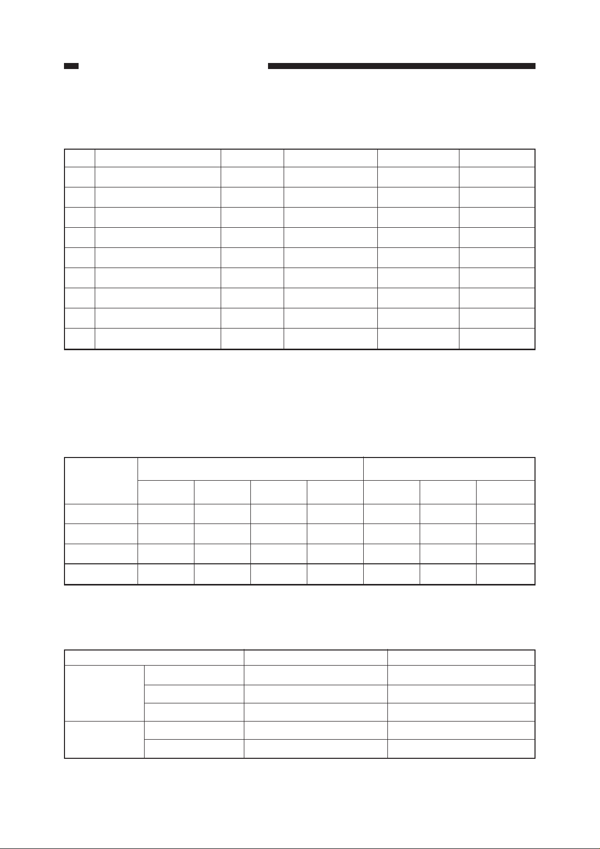
3. Mechanism
Print mode/Resolution
(No.) Mode Pass *
(1) Monochrome draft 1 pass/Bi 180dpi x 360dpi 14.4kHz M
(2) Monochrome normal 1 pass/Uni 360dpi x 360dpi 7.2kHz L
(3) Monochrome enhanced 2 pass/Uni 360dpi x 360dpi 7.2kHz L
(4)
Monochrome high enhanced
(5)
Monochrome high resolution
4 pass/Uni 360dpi x 360dpi 7.2kHz L
4 pass/Uni 720dpi x 720dpi*
(6) Color draft 1 pass/Bi 360dpi x 360dpi 7.2kHz Bk:M/Color:S
(7) Color normal 1 pass/Uni 360dpi x 360dpi 7.2kHz Bk:L/Color:S
(8) Color enhanced 2 pass/Uni 360dpi x 360dpi 7.2kHz Bk:L/Color:S
(9) Color high enhanced 4 pass/Unil 360dpi x 360dpi 7.2kHz Bk:L/Color:S
1
Resolution
Drive frequency
2
7.2kHz S
Dot size *
3
* 1: Bi=bi-directional, Uni=uni-directional
* 2: Equivalent
* 3: S=small dot, M=middle dot, L=large dot
Table 1-101
Print modes according to media type <Corresponds to the Nos. of table 1-101.>
Media type Monochrome Color
Draft Normal Enhanced
High resolution
Draft Normal Enhanced
Plain paper (1) (2) (3) (5) (6) (7) (8)
Coated paper (1) (2) (3) (5) (7) (8) (9)
Tracing paper (2) (3) (4) (5) (7) (8) (9)
Matte film (2) (3) (4) (5) (7) (8) (9)
Table 1-102
Maximum printing speed (Plain paper mode)
Monochrome
mode
Color mode
1–2
Print mode A0 size A1 size
Draft mode Approx. 2 minutes 15 seconds Approx. 1 minute 30 seconds
Enhanced mode Approx. 13 minutes Approx. 7 minutes
High Resolution mode
Approx. 25 minutes Approx. 13 minutes 15 seconds
Draft mode Approx. 5 minutes 15 seconds Approx. 3 minutes
Enhanced mode Approx. 15 minutes Approx. 8 minutes 30 seconds
Table 1-103

CHAPTER 1. GENERAL DESCRIPTION
Cartridge construction Head/Ink tank separation type
1 row of 160 nozzles (144 nozzles used) x 4 colors
Ink type Black: Pigment, Cyan/Magenta/Yellow: dye
Ink tank capacity Black: Approx. 23g,
Cyan/Magenta/Yellow: Approx. 20g
BJ print head service life A0 size: Approx. 400 sheets, A1 size: Approx. 500
sheets
(continuous printing on plain paper, 1-pass uni-
directional, at 20% duty (5% for each color))
Ink consumption A0 size: Bk; 25 sheets,
Cyan/Magenta/Yellow; 40 sheets
A1 size: Bk; 50 sheets,
Cyan/Magenta/Yellow; 80 sheets
(continuous printing on plain paper, 1-pass unidirectional, at 20% duty (5% for each color))
Interface Parallel interface
Complies with IEEE1284 (Compatible mode/Nibble
mode)
Connector complying with IEEE1284-B Receptacle
Serial interface
Complies with RS-232C (DCE)
D-Sub 9-pin female connector
Emulation Complies with HP-GL, HP-GL/2, and HP-RTL
Kanji font Kanji JIS first and second standard
Memory Standard: 8MB (can be increased to 72 MB: 72-pin
60ns FPM type SIMMs)
EDO memory can be used in FPM mode.
Cutter Automatic cutter (replaceable)
Waste-ink tank Provided
Maintenance jet Provided
Capping system Provided
Paper thickness adjustment Provided
Automatic printing position adjustment Provided
Self diagnostics Provided
Skewed feed detection Provided
Head detection Provided
Head insertion error detection Not provided
1–3

CHAPTER 1. GENERAL DESCRIPTION
Ink tank detection Provided
Remaining ink detection Provided
Waste-ink full detection Provided
Media out detection Provided
Remaining roll media detection Not provided
Roll media end detection Provided
Media size detection
Cut sheet media: Automatic vertical/horizontal
Roll media: Vertical; size or data designated
Carriage position detection Provided
Machine internal temperature detection Provided
detection
Horizontal; automatic detection
4. Media
Media types Plain paper, coated paper, tracing paper, and matte
film (75 ~ 100µm)
Paper thickness 75 ~ 165µm (excluding matte film) / 64 ~ 128g/m
Maximum paper width A0 model: 914mm
A1 model: 634mm
Minimum paper width/length Width; 250mm Length; 150mm
Maximum printing length Cut sheet media: 1250mm
Roll media* : Windows95/98 driver; 4.6m
WindowsNT4.0 driver; 4.6m
ADI driver; 13m
HDI driver; 18m
* : Printing length of roll media varies depending on the type of application, operating system, or driver used.
Printing margin Cut sheet media: Leading edge; 5mm/15mm
2
Trailing edge; 20mm
Right/left edge; 5mm
Roll media: Leading edge; 5mm/15mm
Trailing edge; 5mm
Right/left edge; 5mm
Maximum printing area Excludes printing margins
1–4

CHAPTER 1. GENERAL DESCRIPTION
Printable papers
Paper standard mm inch A1 model A0 model
ISO A Vertical Horizontal Vertical Horizontal
A0 841.0 × 1189.0 33.1 × 46.8 NG NG OK NG
A1 594.0 × 841.0 23.4 × 33.1 OK NG OK OK
A2 420.0 × 594.0 16.5 × 23.4 OK OK OK OK
A3 297.0 × 420.0 11.7 × 16.5 OK OK OK OK
A4 210.0 × 297.0 8.3 × 11.7 NG OK NG OK
JIS B
B1 728.0 × 1030.0 28.7 × 40.6 NG NG OK NG
B2 515.0 × 728.0 20.3 × 28.7 OK NG OK OK
B3 364.0 × 515.0 14.3 × 20.3 OK OK OK OK
B4 257.0 × 364.0 10.1 × 14.3 OK OK OK OK
ISO B
B1 707.0 × 1000.0 27.8 × 39.4 NG NG OK NG
B2 500.0 × 707.0 19.7 × 27.8 OK NG OK OK
B3 353.0 × 500.0 13.9 × 19.7 OK OK OK OK
B4 250.0 × 353.0 9.8 × 13.9 OK OK OK OK
ANSI
E 863.6 × 1117.6 34.0 × 44.0 NG NG OK NG
D 558.8 × 863.6 22.0 × 34.0 OK NG OK OK
C 431.8 × 558.8 17.0 × 22.0 OK OK OK OK
B 279.4 × 431.8 11.0 × 17.0 OK OK OK OK
A 215.9 × 279.4 8.5 × 11.0 NG OK NG OK
ANSI ARCH
6 914.4 × 1219.2 36.0 × 48.0 NG NG OK NG
5 762.0 × 1066.8 30.0 × 42.0 NG NG OK NG
4 609.6 × 914.4 24.0 × 36.0 OK NG OK OK
3 457.2 × 609.6 18.0 × 24.0 OK OK OK OK
2 304.8 × 457.2 12.0 × 18.0 OK OK OK OK
1 228.6 × 304.8 9.0 × 12.0 NG OK NG OK
ISO Over
A0 910.0 × 1245.0 35.8 × 49.0 NG NG OK NG
A1 627.0 × 900.0 24.7 × 35.4 OK NG OK OK
A1L 627.0 × 1250.0 24.7 × 49.2 OK NG OK NG
A2 460.0 × 645.0 18.1 × 25.4 OK NG OK OK
A3 340.0 × 465.0 13.4 × 18.3 OK OK OK OK
EURO DIN
A0 881.0 × 1229.0 34.7 × 48.4 NG NG OK NG
A1 634.0 × 881.0 25.0 × 34.7 OK NG OK OK
A2 460.0 × 634.0 18.1 × 25.0 OK OK OK OK
A3 337.0 × 460.0 13.3 × 18.1 OK OK OK OK
A4 250.0 × 337.0 9.8 × 13.3 OK OK OK OK
KOREAN
m 540.0 × 790.0 21.3 × 31.1 OK NG OK OK
s 390.0 × 540.0 15.4 × 21.3 OK OK OK OK
1–5

CHAPTER 1. GENERAL DESCRIPTION
5. Others
Power source AC: 100 ~ 240 V (-15%, +10%)
Frequency 50/60Hz
Power consumption Max.: 120W or less
At stand-by: 22W or less
Noise Sound pressure level (Complies with ISO 9296.)
When operating: Approx. 52dB (A) or less
At stand-by: Approx. 20dB (A) or less
Operating environment Temperature: 5 ~ 35°C
(Printing quality assured: 15 ~ 30°C)
Humidity: 10 ~ 90%RH
(Printing quality assured: 20 ~ 80%RH)
Atmospheric pressure: 1013 ~ 709hPa
Storage environment* Temperature: 0 ~ 35°C
Humidity: 5 ~ 95% (RH)
* : Should be free from condensation and rapid temperature variations.
1–6
CHAPTER 1. GENERAL DESCRIPTION
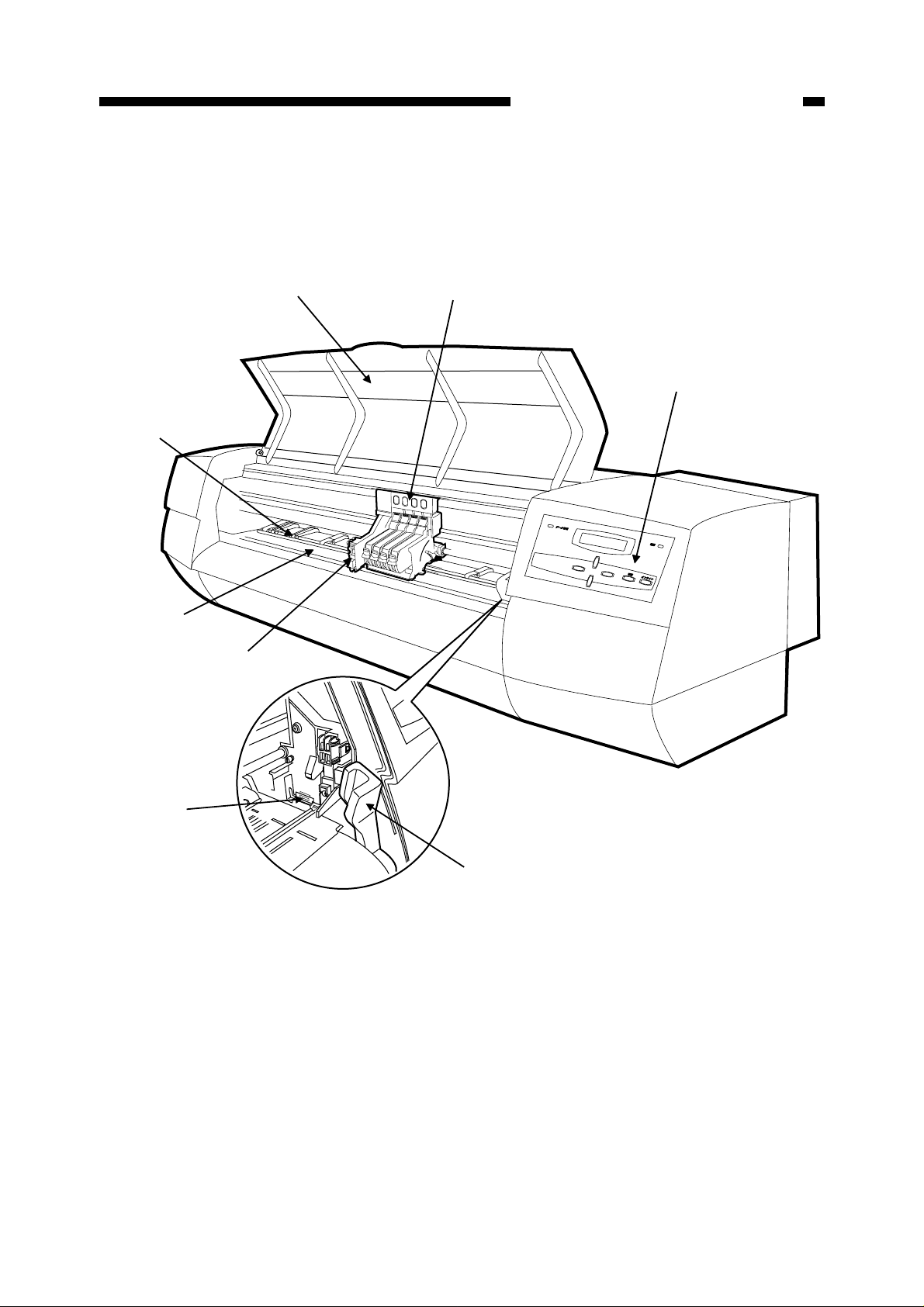
II. NAMES OF COMPONENTS
A. External View
[8]
[7]
[6]
[1]
[2]
[3]
[5]
[1] Front cover
[2] Carriage
[3] Operation panel
[4] Paper release lever
[4]
[5] Wiper (Cleaner blade)
[6] Cutter unit
[7] Platen
[8] Pinch roller
Figure 1-201
1–7
CHAPTER 1. GENERAL DESCRIPTION
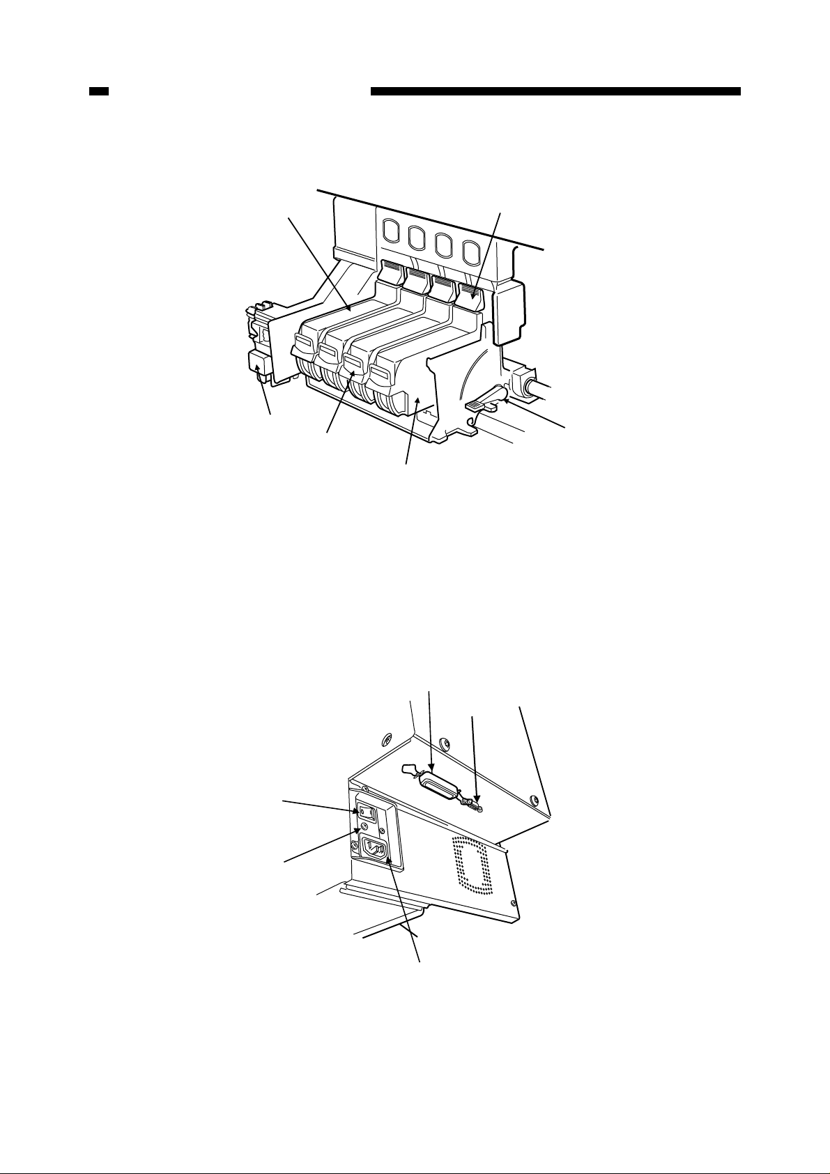
B. Carriage
[1]
[6]
[5]
[1] Ink tank
[2] BJ print head release hook
[3] Paper thickness adjustment lever
[2]
[3]
[4]
[4] BJ Cartridge
[5] Ink tank release hook
[6] Cutter unit
C. Cable Connections
[5]
[4]
[1] Parallel interface connector
Figure 1-202
[1]
[2]
[3]
[4] Earth wire terminal
[2] Serial interface connector
[3] AC inlet
1–8
[5] Power switch
Figure 1-203
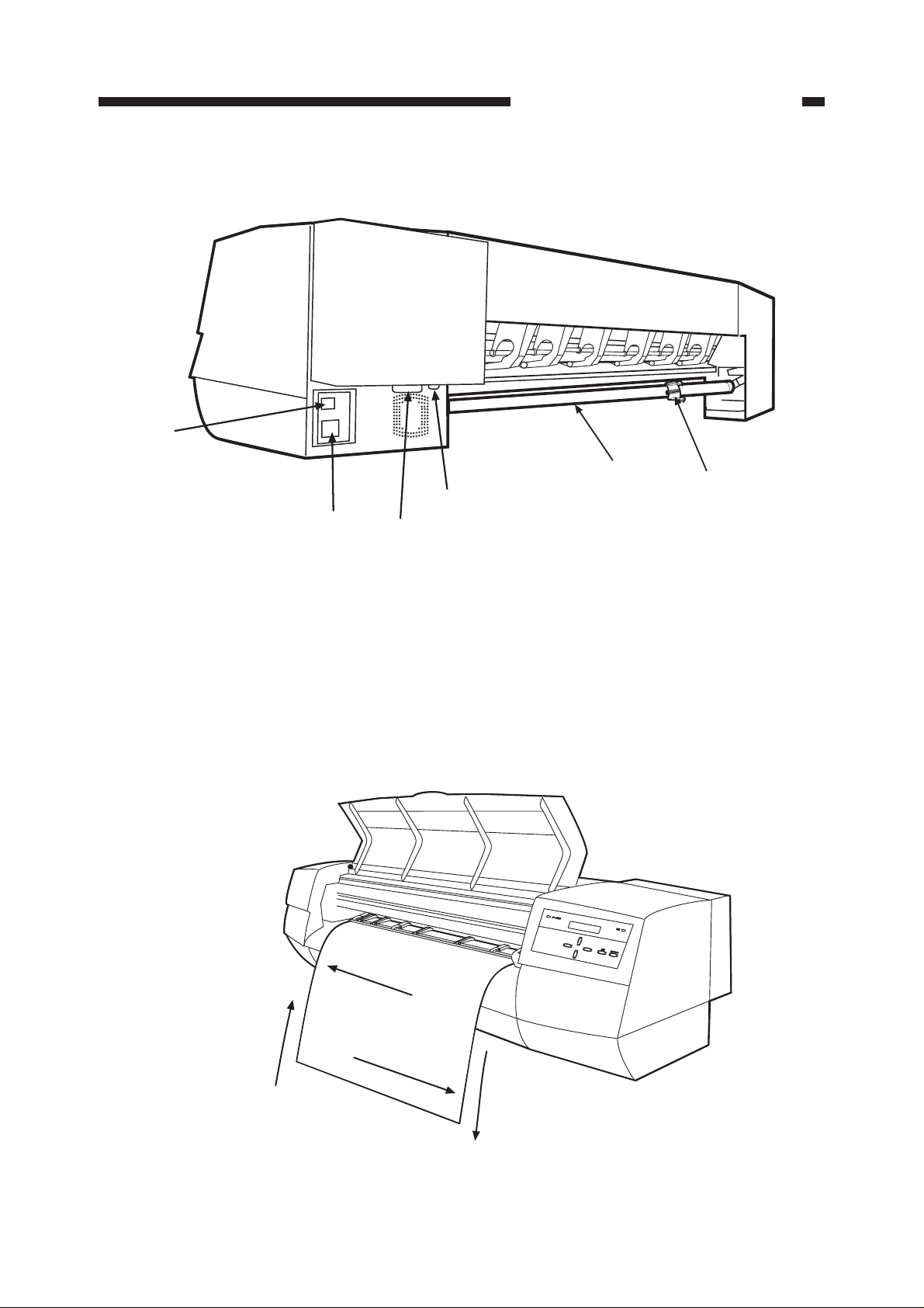
D. Rear Side of Main Unit
[6]
CHAPTER 1. GENERAL DESCRIPTION
[1] Roll media stopper
[2] Spindle
[3] Serial interface connector
E. Printing Direction
[5]
[3]
[4]
Figure 1-204
[2]
[1]
[4] Parallel interface connector
[5] AC inlet
[6] Power switch
Paper feed
backward direction
Carriage
forward direction
Carriage
backward direction
Paper feed
forward direction
Figure 1-205
1–9
CHAPTER 1. GENERAL DESCRIPTION
III. OPERATION
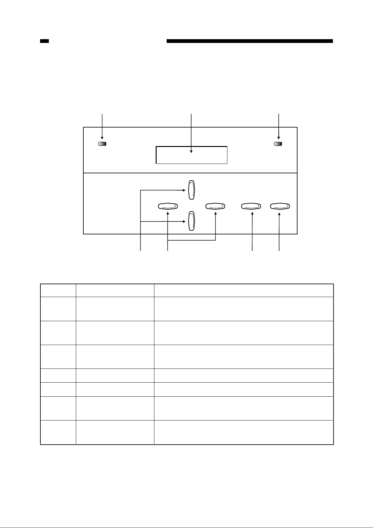
A. Operation Panel
[1]
DATA
[7]
[6]
[2] [3]
POWER
ENTER
Figure 1-301
No. Name Function
ONLINE
[4][5]
[1] Data reception lamp Green when receiving data. Blinks if data is transmitted
when the printer cannot receive it.
[2] Message display Menus, parameters, error messages and other conditions
are displayed. Divided into upper and lower sections.
[3] Power lamp Green when power switch is turned on. Orange in the
sleep state. Blinks orange if an error occurs.
[4] Online key Switches between the online, offline and menu states.
[5] Enter key Enters selected menu item.
[6] Right/left arrow keys Used when selecting parameters. Also used to move the
carriage on the platen.
[7] Up/down arrow keys Used when selecting menus. Can move the paper back
and forth when offline.
Table 1-301
1–10
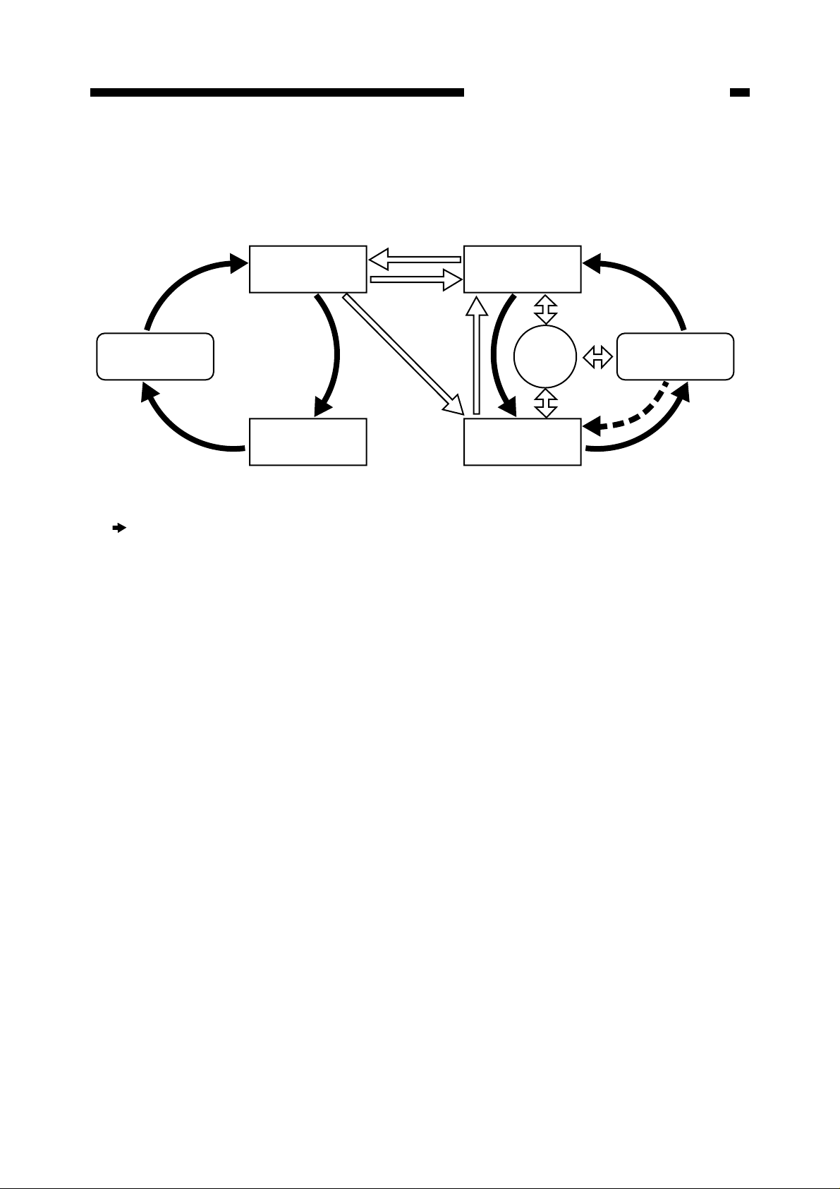
B. Printer States
Printer states and key operation are shown below.
Data received
CHAPTER 1. GENERAL DESCRIPTION
Printing
After printing on cut sheet media
*1
Menu setup screen
Pause
(Black arrows) : Change of printer states when the Online key is pressed.
*1. Some menus cannot be setup during printing.
*2. When no media is loaded, the machine cannot be returned to the “Online” state by pressing the Online key.
It returns to “Offline”.
*3. Pressing any key on the control panel, opening the front cover, or receiving data in "Sleep" state will wake the printer up.
After printing
on roll media
Online
Media setup
Offline
Sleep
*3
Menu setup screen
*2
Figure 1-302
1–11

CHAPTER 1. GENERAL DESCRIPTION
State Printer state
Online
Offline
Pause
Menu
¥ This machine can receive, analyze and print data. When printing is
started, "Printing" appears on the message display.
¥ While online, only the online key is functional. To use the other keys,
this machine should be offline or in the menu state.
¥ If no data is received for 5 minutes in this state, the printer enters the
sleep state.
¥ If data is transmitted from the host in the offline state, the printer will
ignore it.
¥ The roll media can be fed and the carriage can be moved.
¥ If no data is received for 20 minutes, the printer enters the sleep state.
¥ Printing is paused. As long as, there is sufficient space in the buffer
memory, data is received and analyzed continuously. When the reception
buffer becomes almost full in the pause state, the mode is shifted to
receive data at 1 byte/sec.
¥ By pressing the online key in the pause state, the printer will enter the
menu state.
¥ Menus and parameters can be set up. The menu items available when
paused are more limited than those available when in offline state.
Printing
Sleep
¥ The printer is printing.
¥ The operation panel keys cannot be used in the printing state. To use
the keys, the printer should be in the pause or menu state.
¥ All lamps and the display (other than the power lamp) are off.
¥ When paper is loaded and data is transmitted from the host, the printer
automatically enters the online state and starts printing.
Table 1-302
1–12
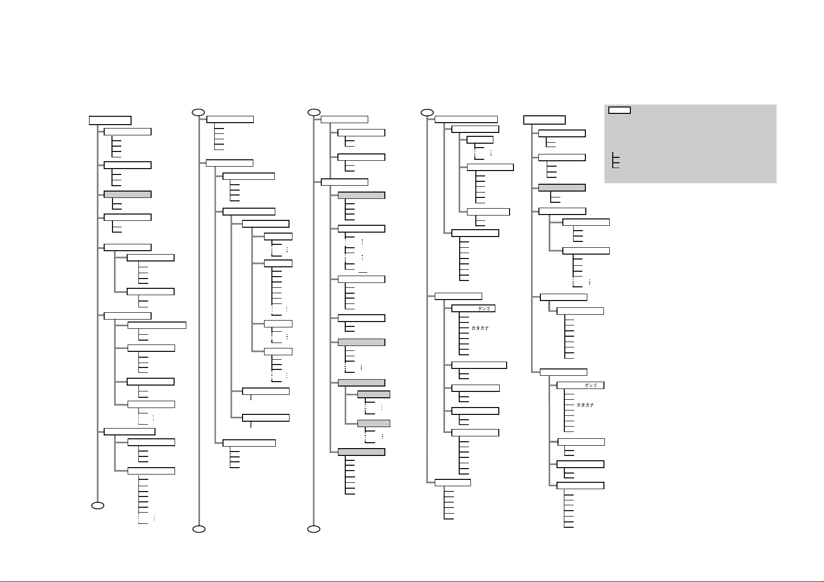
C. User Mode Menu
1. Menu guide
The following diagram shows the menu hierarchy of this printer.
Normal menu
Main menu
Print Operation
Abort Print
Buffer Clear
Replot
Force Print
Head Cleaning
All
Black
New T ank
Force Cutting
Yes
No
Adjustment
Auto Adjust
Auto Band-Adj.
Print Mode
Print Quality
Color/Mono
Media setup
Roll/Cut Sheet
Media Type
Margin
Copy
Auto Cut
Cut Type
Drying Time
A
Normal
Enhanced
Hi-Resolution
Draft
Color
Mono
Roll Media
Cut Sheet
Plain Paper
Coated Paper
Tracing Paper
Film
Normal
Large
1
99
Cut
Cut Line
No Cut
Off
Auto
30 seconds
1 minute
2 minutes
5 minutes
10 minutes
60 minutes
A
Emulation
Auto Sense
HP-GL
HP-GL/2+RTL
HP RTL
TIFF
Pen Setup
Select Tab le
Software
Pen T ab le 1
Pen T ab le 2
Pen T ab le 3
Modify Tab le
Pen T ab le 1
Pen
*1
*1
*1
*1
*1
Reset Tab le
*1
Width
Color
Join
Pen T ab le 2
(*Same as Pen Table 1)
Pen T ab le 3
(*Same as Pen Table 1)
Pen T ab le 1
Pen T ab le 2
Pen T ab le 3
All Pen Table
31
255
B
Line Type
Line Intersect
Overlay
Merge
Line Shading
On
Off
Print Layout
Auto Layout
Off
Nesting
Media Save
Best
Scale
0
15
1
2
3
4
5
7
9
0
1
2
3
9
100%
999%
99%
Auto
Rotation
180°
270°
Auto
Y-Mirror
Off
On
Layout Size
ISO-A
ISO-B
JIS-B
User
User Size
Nesting Timer
30 seconds
1 minute
2 minutes
5 minutes
10 minutes
30 minutes
60 minutes
1%
0°
90°
Length
Width
*2
*2
80mm
18000mm
80mm
627mm (914mm)
C
Internal Print
Interface Setup
RS-232C
EOP Timer
System Setup
Language ( )
Auto Adjust Mode
Feed Priority
Reset Defaults
Information
Demonstration
Menu Map
Color Palette
Setup List
Nozzle Check
Dump Mode
Baud Rate
2400bps
38400bps
Data Bit-Parity
7none
7even
7odd
8none
8even
8odd
Handshake
Hardware
Xon/Xoff
10 seconds
30 seconds
1 minute
2 minutes
5 minutes
10 minutes
30 minutes
60 minutes
English(mm)
English(inch)
Francais
Deutsch
Italiano
Espanol
Svenska
On
Off
Print Length
Band Joint
Yes
No
I/C: Ver.
I/Boot: Ver .
E/C: Ver .
E/Boot: Ver .
E/Slv: Ver .
Memory
Error
CB
Printing Menu
Main Menu
Print Operation
Abort Print
Buffer Clear
Head Cleaning
All
Black
New T ank
Force Cutting
Yes
No
Auto Cut
Cut Type
Drying Time
Interface Setup
EOP Timer
System Setup
Language ( )
Auto Adjust Mode
Feed Priority
Information
Cut
Cut Line
No Cut
Off
Auto
30 seconds
1 minute
60 minutes
10 seconds
30 seconds
1 minute
2 minutes
5 minutes
10 minutes
30 minutes
60 minutes
English(mm)
English(inch)
Francais
Deutsch
Italiano
Espanol
Svenska
On
Off
Print Length
Band Joint
I/C: Ver.
I/Boot: Ver .
E/C: Ver .
E/Boot: Ver .
E/Slv: Ver .
Memory
Error
: Indicates the menu
(Select the item using the up and down arrow keys.)
(The shaded items are indicated only in the roll media mode.)
*1: Can be set as a printer driver property, This fares priority
over the operation panel setting when printing using the driver.
*2: Can be set as a printer driver property, but both this setting
and that of the operation panel will affect the printing.
xxx
: Indicates set value.
xxx
Press the right or left arrow key to accept the set value.
xxx
Press the ENTER key to accept or execute the selection.
(Underlined items are indicated only in the cut sheet media
mode.)
1-13

CHAPTER 1. GENERAL DESCRIPTION
2. Menu and parameter setup
Menus and parameters are selected as described below.
1) By pressing the online key in the offline or pause state, the printer enters the menu state.
2) Select a menu item by pressing the right and left arrow keys.
3) After selecting a menu, move to the parameter menu by pressing the down arrow key.
CAUTION
Menu display varies depending on the state. (offline or pause)
4) Select parameters by pressing the right and left arrow keys.
5) Accept the selected parameter by pressing the Enter key.
CAUTION
When "Head Cleaning", "Force Cutting" or other item for immediate execution is selected,
the operation is started by pressing the Enter key. If the up arrow key is pressed instead, the
operation will not start and the selected parameter is cancelled.
3. Details of user mode menus
The user mode menus are shown below.
[1] Print Operation
Used to change the current print operation.
• Abort Print
Printing is stopped in the pause state.
• Buffer Clear
All current operations are stopped from
• Replot
The data printed last is printed again.
• Force Print
The EOP timer is started and the printer
is forced to print from the printing
stand-by state.
in the offline or pause state, and all
printing data in the memory are cleared.
1–14

CHAPTER 1. GENERAL DESCRIPTION
[2] Head Cleaning
Used to clean the cartridge heads.
• All
All heads are cleaned.
• Black
Only the black head is cleaned.
• New Tank
If the ink tank has been removed, use this
menu to prevent non-discharge of ink.
[3] Force Cutting
Used to cut the set paper.
Paper is cut.
• Yes
Paper is cut.
•No
Paper is not cut.
[5] Print Mode
a. Print Quality
[Default: Normal]
The print quality can be selected for the
type of data or paper.
• Draft
For higher-speed, lower-quality output.
• Normal
For printing line drawings, etc.
• Enhanced
For printing files including graphics or
solid printing.
• High-Resolution (monochrome only)
For printing monochrome line drawings at an equivalent resolution to 720
dpi.
[4] Adjustment
• Auto Adjust
Printing position is automatically
adjusted.
• Auto Band-Adj.
Paper feed rate is automatically
adjusted.
b. Color/Mono
[Default: Color]
Monochrome or color mode can be se-
lected.
• Color
Color data will be printed in color.
• Mono
Color data will be printed in gray scale.
1–15

CHAPTER 1. GENERAL DESCRIPTION
[6] Media Setup
Used to change paper settings.
a. Roll/Cut Sheet
[Default: Previous setting preserved]
Select roll media or cut sheet.
• Roll Media
Select this to use roll media. If a cut
sheet is loaded, it will be ejected.
• Cut Sheet
Selected when cut paper is used. If roll
media is loaded, it is reverse fed and
withdrawn.
b. Media Type [Default: Plain paper]
[7] Auto Cut
a. Cut Type
[Default: Cut]
Select the type of cut for roll media after
completion of printing.
•Cut
Cuts the roll media automatically after
completion of printing.
• Cut Line
After completion of printing, a cutting
line is printed.
• No Cut
After completion of printing, the roll
media is not cut.
The following media types can be se-
lected:
• Plain Paper
• Coated Paper
• Tracing Paper
• Film
c. Margin [Default: Normal]
Margin size at the media leading edge can
be selected.
• Normal
Leaves a margin of 5mm.
• Large
Leaves a margin of 15mm.
d. Copies [Default: 1]
Specify the number of copies to be
b. Drying Time (only for roll media)
[Default: Off]
Sets the time for drying the ink after
completion of printing.
•Off
Paper is ejected as usual.
• Auto
Optimum drying time is automatically
selected according to the media type and
printing mode.
In the case of draft mode, the drying
time is the same as for [Off].
• 30 sec., 1 min., 2 min., 5 min.,
10 min., 20 min., 30 min., 40 min.,
50 min., 60 min.
printed.
1 - 99
1–16

CHAPTER 1. GENERAL DESCRIPTION
CAUTION
In the draft mode, the ink may not
dry, depending on the environment.
Set the drying time as required.
REFERENCE
Drying time for each media type is as
follows:
• Plain paper: 30 sec.
• Coated paper: none
• Tracing paper: 2 min.
• Film: 7 sec.
[8] Emulation
• HP RTL
Should only be used when printing
raster data. After the raster data is
received and 1 band is analyzed, printing is started.
• HP-GL (759x)
Conforms to the HP-759X series
format.
[9] Pen Setup
Composed of the pen setup selection
menu, pen table changing menu, and pen
table initialization menu.
a. Select Table
[Default: Auto Sense]
Emulation can be set to match the file type
output from the computer.
• Auto Sense
HP-GL/2+RTL, HP RTL, HP-GL, and
TIFF data is automatically detected and
printed.
• HP-GL/2+RTL
Emulates HP-GL/2 and HP-RTL. Data
is accumulated in the memory buffer
and printing is started with the EOP
command, or when the EOP timer times
out.
[Default: Software]
Specifies whether to use the setting desig-
nated by the software or the pen table setting.
• Software
Pen setup from the application is
used. (See Table 1-305.)
• Pen Table (1 to 3)
Pen setup (pen table) stored in the
printer can be used. (See Table 1-304.)
1–17
 Loading...