

Canon AM1 Service Manual

Revision 1.0
Cassette Feeding Unit-AM1
Service Manual

Contents
Safety Precautions...............................................................................................5
Notes Before it Works Serving............................................................................................................ 6
Product Overview.................................................................................................7
Specifications...................................................................................................................................... 8
Parts Name......................................................................................................................................... 9
Technology......................................................................................................... 10
Overview........................................................................................................................................... 11
Drive Configuration............................................................................................................................12
Lifter Control......................................................................................................................................13
Cassette Pickup Control....................................................................................................................14
Cassette Paper Size Detection......................................................................................................... 15
Cassette Detection............................................................................................................................17
Paper Level/Presence Detection.......................................................................................................18
Periodical Service.............................................................................................. 20
Disassembly/Assembly..................................................................................... 21
List of Parts....................................................................................................................................... 22
Electrical Components List...................................................................................................................22
List of Connectors............................................................................................................................... 24
Parts Replacement Procedure.......................................................................................................... 26
Preface...............................................................................................................................................26
Removing from the Host Machine.........................................................................................................26
Removing the Pickup/Feed/Separation Roller....................................................................................... 30
Removing the Cassette 3/4 Pickup Unit................................................................................................ 30
Removing the Cassette Pedestal Driver PCB........................................................................................34
Adjustment......................................................................................................... 36
Image Position Adjustment................................................................................................................37
Hardware Adjustment..........................................................................................................................37
Software adjustment............................................................................................................................40
Margin Adjustment (First side; Mechanical Adjsutment)................................................................... 41
Margin Adjustment (Second side)..................................................................................................... 44
Installation.......................................................................................................... 45
How to Check the Installation Procedure.......................................................................................... 46
Symbols............................................................................................................................................. 46
Unpacking......................................................................................................................................... 47
Checking before Installation..............................................................................................................49
Check Item When Turning OFF the Main Power....................................................................................49
Contents
i

Installation Outline Drawing................................................................................................................. 49
Checking the Contents........................................................................................................................ 49
Installation Procedure........................................................................................................................50
Setting the Cassette..........................................................................................................................54
Adjustment........................................................................................................................................ 56
Margin Adjustment (First side; Mechanical Adjsutment)......................................................................... 56
Margin Adjustment (Second side).........................................................................................................57
General Circuit Diagram....................................................................................................................58
General Circuit Diagram...................................................................................................................... 58
Contents
ii

Introduction
Important Notices
Application
This manual has been issued by Canon Inc. for qualified persons to learn technical theory, installation, maintenance, and repair
of products.
This manual covers all localities where the products are sold. For this reason, there may be information in this manual that does
not apply to your locality.
Corrections
This manual may contain technical inaccuracies or typographical errors due to improvements or changes in products.
When changes occur in applicable products or in the contents of this manual, Canon will release technical information as the
need arises. In the event of major changes in the contents of this manual over a long or short period, Canon will issue a new
edition of this manual.
The following paragraph does not apply to any countries where such provisions are inconsistent with local law.
Trademarks
The product names and company names used in this manual are the registered trademarks of the individual companies.
Copyright
This manual is copyrighted with all rights reserved. Under the copyright laws, this manual may not be copied, reproduced or
translated into another language, in whole or in part, without the consent of Canon Inc.
Copyright CANON INC. 2016
Caution
Use of this manual should be strictly supervised to avoid disclosure of confidential information.
Explanation of Symbols
The following symbols are used throughout this Service Manual.
Symbols Explanation Symbols Explanation
Check.
1x
Remove the claw.
Check visually.
1x
Insert the claw.
Check a sound. Push the part.
Introduction
3

Symbols Explanation Symbols Explanation
1x
Disconnect the connector. Connect the power cable.
1x
Connect the connector. Disconnect the power cable.
1x
Remove the cable/wire from the
cable guide or wire saddle.
Turn on the power.
1x
Install the cable/wire to the cable
guide or wire saddle.
Turn off the power.
1x
Remove the screw.
1x
Loosen the screw.
1x
Install the screw.
1x
Tighten the screw.
Cleaning is needed. Measurement is needed.
The following rules apply throughout this Service Manual:
1. Each chapter contains sections explaining the purpose of specific functions and the relationship between electrical and
mechanical systems with reference to the timing of operation.
In the diagrams, represents the path of mechanical drive; where a signal name accompanies the symbol, the arrow
indicates the direction of the electric signal.
The expression "turn on the power" means flipping on the power switch, closing the front door, and closing the delivery unit
door, which results in supplying the machine with power.
2. In the digital circuits, '1' is used to indicate that the voltage level of a given signal is "High", while '0' is used to indicate "Low".
(The voltage value, however, differs from circuit to circuit.) In addition, the asterisk (*) as in "DRMD*" indicates that the DRMD
signal goes on when '0'.
In practically all cases, the internal mechanisms of a microprocessor cannot be checked in the field. Therefore, the operations
of the microprocessors used in the machines are not discussed: they are explained in terms of from sensors to the input of
the DC controller PCB and from the output of the DC controller PCB to the loads.
The descriptions in this Service Manual are subject to change without notice for product improvement or other purposes, and
major changes will be communicated in the form of Service Information bulletins.
All service persons are expected to have a good understanding of the contents of this Service Manual and all relevant Service
Information bulletins and be able to identify and isolate faults in the machine.
Introduction
4

Safety Precautions
Notes Before it Works Serving.................................................. 6
Safety Precautions
5

Notes Before it Works Serving
CAUTION:
At servicing, be sure to turn off the power source according to the specified steps and disconnect the power plug.
CAUTION:
Do not turn off the power switch (of the host machine) when downloading is under way. Turning off the main power switch
while downloading is under way can disable the machine.
Safety Precautions
6

Product Overview
Specifications............................................................................ 8
Parts Name............................................................................... 9
Product Overview
7

Specifications
Item Description
Pickup method Separation retard method
Stacking capacity
(1 cassette)
550 sheets (80 g/m2)
640 sheets (64 g/m2)
Number of cassettes 2 cassettes
Paper feed reference Center reference
Paper type
Thin paper (52 to 63 g/m2), Plain paper (64 to 105 g/m2), Recycled paper (64 to 105 g/m2), Heavy paper (106 to
256 g/m2), Colored paper, Pre-punched paper, Transparency, Clear Film, Bond paper, Letterhead
Paper size A3, B4, A4, A4R, B5, B5R, A5R, 11" x 17", LGL, LTR, LTRR, STMTR, 12" x 18", EXEC, 8K, 16K, 16KR, Custom
size (Width: 98.0 to 304.8 mm, Length: 182.0 to 457.2 mm)
Paper weight
52 to 256 g/m
2
Auto size detection Yes
Environmental measure
Cassette Heater available
Power Supply Supply from the host machine
Dimension (W x D xH)620 x 700 x TBD mm
Weight TBD
Product Overview
8

Parts Name
[1]
[5]
[6]
[7]
[9]
[8]
[2]
[3]
[4]
[10]
[11]
No. Name No. Name
[1] Between-cassette Cover [7] Cassette Connector Cover
[2] Cassette 3 Front Cover [8] Cassette Cover (Right Rear)
[3] Cassette 4 Front Cover [9] Cassette Right Cover (Lower)
[4] Cassette Cover (Lower) [10] Cassette Right Door
[5] Cassette Cover (Left) [11] Cassette Cover (Right Front)
[6] Cassette Cover (Rear)
Product Overview
9

Technology
Overview................................................................................. 11
Drive Configuration..................................................................12
Lifter Control............................................................................13
Cassette Pickup Control..........................................................14
Cassette Paper Size Detection............................................... 15
Cassette Detection.................................................................. 17
Paper Level/Presence Detection.............................................18
Technology
10

Overview
List of Detections/Controls
Drive Configuration
Lifter control
Cassette pickup control
Cassette paper size detection
Cassette detection
Paper level/presence detection
Technology
11
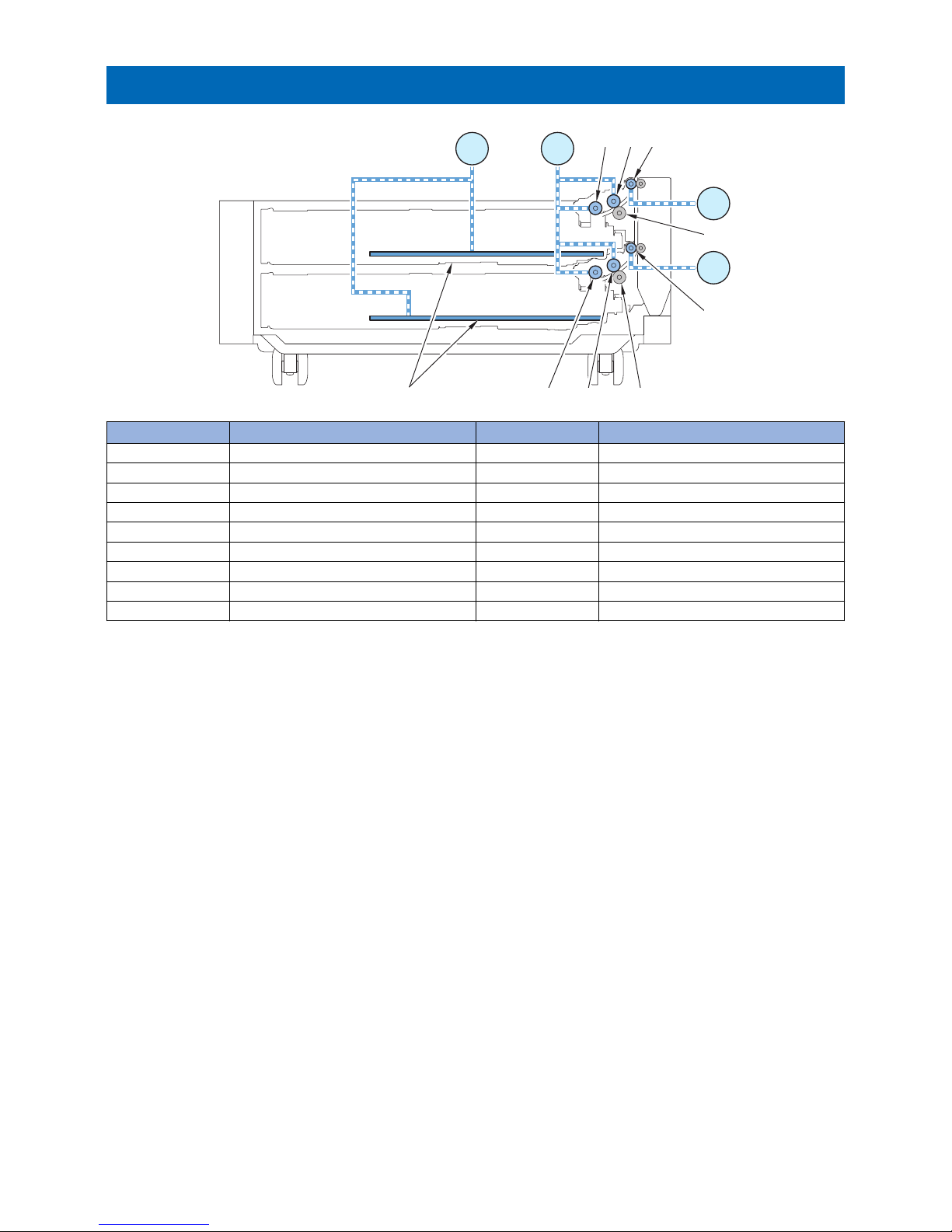
Drive Configuration
M102M101
M103
M104
[3]
[8]
[5]
[9]
[6] [7]
[4][2][1]
No. Name No. Name
[1] Cassette 3 Pickup Roller M101 Cassette 3,4 Lifter Motor
[2] Cassette 3 Feed Roller M102 Cassette 3, 4 Pickup Motor
[3] Cassette 3 Separation Roller M103 Cassette 3 Pullout Motor
[4] Cassette 3 Pullout Roller M104 Cassette 4 Pullout Motor
[5] Cassette 4 Pickup Roller
[6] Cassette 4 Feed Roller
[7] Cassette 4 Separation Roller
[8] Cassette 4 Pullout Roller
[9] Lifting Plate
Technology
12

Lifter Control
Paper inside a cassette is lifted up by the Lifting Plate.
The Lifting Plate is lifted up by rotating the Cassette 3,4 Lifter Motor (M101).
When paper surface reaches the position of the Pickup Roller, the Cassette 3/4 Paper Surface Sensor is turned ON (PS107/
PS108) to detect that the paper has reached the pickup position.
Lifter Error Detection
When the Cassette Paper Surface Sensor is not turned ON although the Cassette Lifter Motor is driven, an alarm is issued due
to error in pickup assembly.
However, at first and second failure of paper surface detection, Trailing Edge Guide Plate error is displayed on the Control Panel
to prompt the user to open and then close the cassette.
If paper surface detection fails for 3 consecutive times, no paper is displayed for the cassette and an alarm is issued.
While an alarm has occurred, the corresponding cassette cannot be used.
<Related alarm codes>
• 04-0003: Cassette 3 Lifter error
• 04-0004: Cassette 4 Lifter error
Technology
13

Cassette Pickup Control
Rotation of the Cassette Pickup Motor feeds paper to the Cassette Pullout Roller.
The Cassette 3/4 Pickup Roller and the Cassette 3/4 Feed Roller are driven by the Cassette 3,4 Pickup Motor (M102) while the
Cassette 3,4 Pullout Roller is operated by the rotation of the Cassette 3,4 Pullout Motor (M103/M104).
Pickup Retry Error
Pickup retry is executed when a delay jam is detected by the Pullout Sensor of each cassette.
An alarm code is notified when pickup fails the predetermined number of times.
<Related alarm codes>
• 04-0013: Cassette 3 Pickup Retry Error
• 04-0014: Cassette 4 Pickup Retry Error
Technology
14

Cassette Paper Size Detection
Size detection is performed to paper set in the cassette, and paper size is determined according to the setting of Paper Size
Group for Auto Recognition in Drawer (A/B size, Inch size, A/K size).
Result of size detec-
tion in each cassette
Paper Size Group for Auto Recognition in Drawer*1
All sizes A/B size Inch size A/K size
A3 A3 A3 No corresponding size A3
B4 B4 B4 No corresponding size No corresponding size
A4-R A4-R A4-R No corresponding size A4-R
A4 A4 A4 No corresponding size A4
B5-R B5-R B5-R No corresponding size No corresponding size
B5 B5 B5 No corresponding size No corresponding size
A5-R Depends on the setting*2 A5R STMT-R A5-R
11x17 11x17 No corresponding size 11x17 No corresponding size
LGL LGL No corresponding size LGL No corresponding size
LTR LTR No corresponding size LTR No corresponding size
LTR-R LTR-R No corresponding size LTR-R No corresponding size
STMT-R Depends on the setting*2 A5-R STMT-R A5-R
12x18 12x18 No corresponding size 12x18 No corresponding size
EXEC Depends on the setting*3 No corresponding size EXEC 16K
8K 8K No corresponding size No corresponding size 8K
16K Depends on the setting*3 No corresponding size EXEC 16K
16K-R 16K-R No corresponding size No corresponding size 16K-R
Envelope Blank unless "Paper Settings" is performed due to non-standard size
Custom size
*1: Set the paper size you want to perform automatic size detection in the cassette in the following Setting/Registration.
• Settings/Registration > Preferences > Paper Settings > Paper Size Group for Auto Recognition in Drawer
NOTE:
The default settings by region are shown below.
Location Default setting
US Inch size
CN A/K size
Other than above A/B size
*2: Set whether to support A5-R or STMT-R in the following Settings/Registration.
• Settings/Registration > Preferences > Paper Settings > A5R/STMTR Paper Selection
*3: Set whether to support EXEC or 16K in the following service mode (Lv. 2).
• Cassette 3:
• COPIER > OPTION > CST > C3-K-SW
• Cassette 4:
• COPIER > OPTION > CST > C4-K-SW
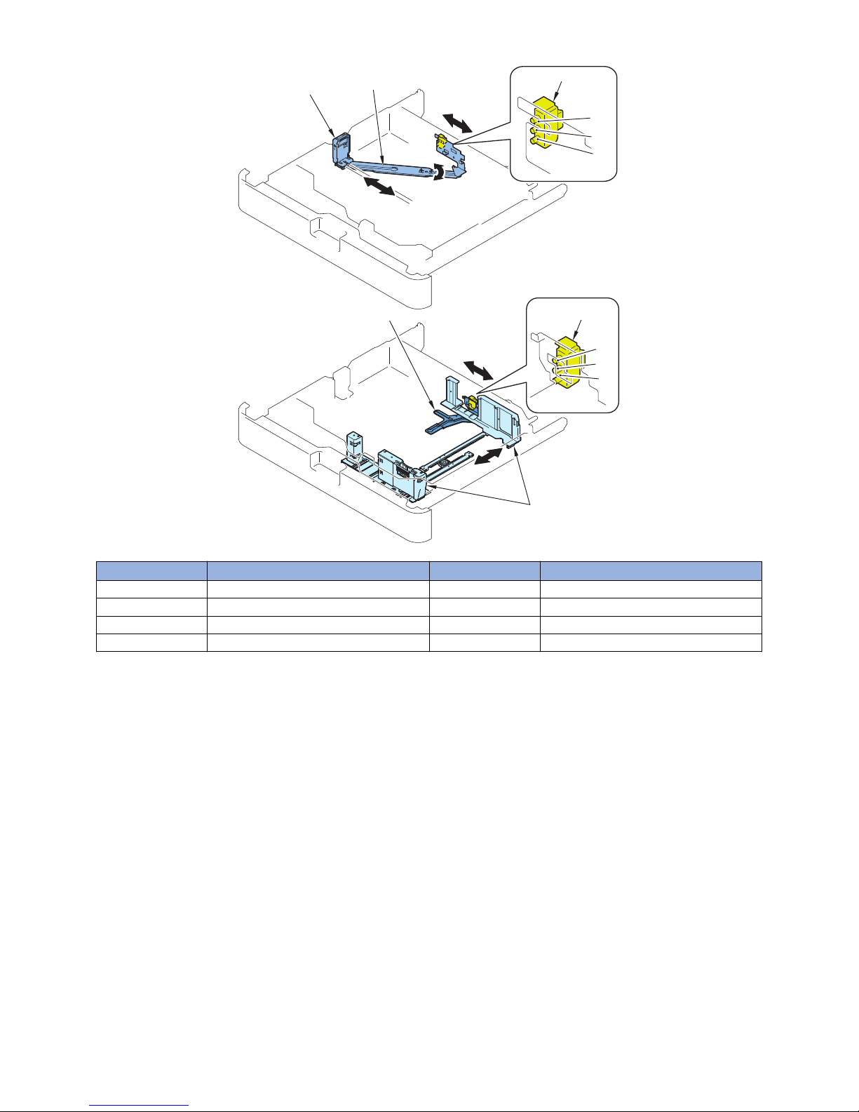
Size Detection
The paper size in the cassette is automatically detected by the Cassette Size Switch A/B after the position of the Guide Plate is
adjusted. The switch consists of 3 microswitches, and length and width are detected in accordance with the combination of ON/
OFF.
• Cassette 3
The Cassette 3 Size Switch B detects width and the Cassette 3 Size Switch A detects length.
• Cassette 4
The Cassette 4 Size Switch B detects width and the Cassette 4 Size Switch A detects length.
Technology
15
SW101/ SW103
[4]
[2]
[1]
[3]
A-1
A-2
A-3
B-1
B-2
B-3
SW102/ SW104
No. Name No. Name
[1] Trailing Edge Guide Plate SW101 Cassette 3 Size Switch A
[2] Link Arm SW103 Cassette 4 Size Switch A
[3] Side Guide Plate SW102 Cassette 3 Size Switch B
[4] Side Detection Plate SW104 Cassette 4 Size Switch B
Technology
16

Cassette Detection
Cassette is detected by the Cassette Size Switch. When none of the following microswitches of the Cassette Size Switch is
pressed, "no cassette" is detected.
• Cassette 3: Cassette 3 Size Switch B (SW102)
• Cassette 4: Cassette 4 Size Switch B (SW104)
Technology
17
 Loading...