

Page 1
®
SimpleVIS
Viscometer
Reference
Guide
P82.0090
Page 2
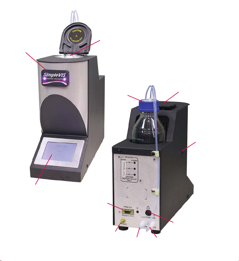
Run Status
Indicator
Lamps
Sample/Solvent Port
Touch Screen
Display
RS-232
Serial
Port
Exhaust Muffler
Waste Bottle
Vacuum Line
Dust Cover
Temperature
Calibration
Port
Power Connector
Waste Line
Page 3

SAFETY CAUTIONS Please observe the following safety procedures
and notices for proper operation of the SimpleVIS® Viscometer.
• Make sure that you read and understand all operating instructions and safety
precautions listed in this manual before installing or operating your unit. If you have
questions regarding instrument operation or documentation, contact CANNON
Instrument Company.
• Do not deviate from the installation, operation or maintenance procedures
described in this guide. Improper use of the SimpleVIS
hazardous situation and may void the manufacturer’s warranty.
• Handle and transport the unit with care. Sudden jolts or impacts may cause
damage to components.
• Do not place the SimpleVIS
SimpleVIS
®
Viscometer should be placed on a level table or bench.
®
Viscometer on an unstable cart or stand. The
• Never operate damaged or leaking equipment.
• Unless procedures specify otherwise, always turn off the unit and disconnect the
mains cable from the power source before performing service or maintenance
procedures, or before moving the unit.
• Never operate the equipment with damaged mains power cables.
• Refer all service and repairs to CANNON
®
Authorized Service Personnel.
CAUTION
In addition to the cautionary statements listed above, additional cautions may be
posted in the manual. These cautions, identified by the symbol at the left indicate
important operational procedures. Read and follow these important instructions.
Protective Conductor
The Protective Conductor Terminal symbol is used to indicate required ground
connections for your instrument electrical supply.
WARNING
When supplying power to this instrument, ensure that the protective ground (earth)
terminals of the instrument are connected to the protective conductor of the
(supplied) line (MAINS) power cord. Use only the manufacturer-supplied power
cord. The main plug for the power cord should only be inserted in a socket outlet
(receptacle) provided with a protective ground (earth) contact. Do not use an
extension cord (power cable) without a protective conductor (grounding).
®
Viscometer may result in a
®
3
Page 4

~MAINS
The ~MAINS symbol indicates instructions or connections for the AC power
supply. The AC Power input must match the electrical specifications listed on the
label on the rear panel of the instrument. The supplied AC Mains power cord
must be attached to the connector labeled ~MAINS. This connection serves as a
means of disconnect and should be readily accessible.
( O )
The (O) symbol indicates the OFF position for the electrical switches for your unit
(AC Mains or accessories).
Hazardous materials
Routine SimpleVIS
handling of hazardous chemicals and solutions. CANNON
®
Viscometer operation may require the use and
®
Instrument Company
strongly urges the operators and technicians working with the SimpleVIS
Viscometer to take proper safety precautions when working with these materials.
These safety procedures can be found in the Material Safety Data Sheets which
accompany the solutions.
SimpleVIS® Viscometer Specifications/Compliance
Product Info. Model: SimpleVIS® Viscometer (Cat. No. 9725-S10)
Applications ISO VG Lubricants, SAE Engine and Gear Oils
Methodology Kinematic Viscosity, ASTM D7279 or ASTM D445-Modifi ed
Test Temperatures 40 or 100 °C - user selectable
Viscosity Range 40°C: 10 – 700 mm2/s (cSt)
Accuracy < 3% of measured value, calibrated
Repeatability < 2% of measured value, typical
Sample Material Type Mineral Oils, Synthetic Oils, Formulated Motor/Gear Oils
Solvent Compatibility Internal wetted components compatible with n-heptane only
Volume Requirements Sample: 450 – 500 μL Solvent: 10 – 15 mL per test
Dimensions 128 mm wide x 356 mm deep x 304 mm high (5x14x12”)
Weight SimpleVIS
Shipping Weight 12.3 kg (27 lbs) with all accessories
Input Power SimpleVIS
AC/DC Adapter
Power Requirements
Operating Conditions 15°-30°C, 10%-90% R.H. non-condensing, Installation Category II, Pollution degree 2
Compliance CE Mark: EMC Directive (2004/108/EC); Low Voltage Directive (2006/95/EC);
4
100°C: 5.5 – 200 mm2/s (cSt)
®
Viscometer unit: 4.6 kg (10.2 lbs)
®
Viscometer Operation Voltage: 11 – 13 VDC @ 5A peak
100~230 Volts, 50/60 Hz, 100 Watts
HI-POT (1900 VDC, 60 sec.); ROHS
®
Page 5
Running a Test
Running a Test
GETTING STARTED
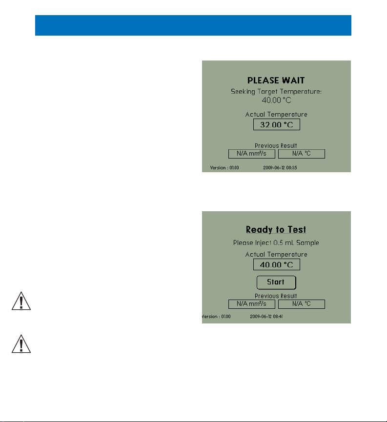
Press the on switch on the AC/DC
adapter. The Warm up Screen will
display a “PLEASE WAIT” message.
During this time, the instrument will
seek the preset target temperature
(40 or 100°C) and when reached, the
instrument will enter an equilibration
period. The equilibration period is 180
seconds.
Note: Refer to the Basic Information
section under Select Target
Temperature for instructions on how
to select the target temperature.
Once the temperature has equilibrated
and the instrument is ready for
measurement, the run status indicator
lamps on front of instrument will
illuminate and the user will be prompted
to inject the sample on the Ready to
Test Screen.
Check the volume of the solvent
container at the beginning of every
work shift to avoid inadequate
washing during testing.
Check the volume of the Waste Bottle
frequently to avoid spillage/overfl ow. Empty the waste bottle when the
volume reaches the 400 mL line marked on the bottle. Refer to the Basic
Maintenance portion of this guide for more information.
Warm up Screen
Ready to Test Screen
5
Page 6

Running a Test
Injecting a sample
1. Using the supplied piston
operated pipettor, insert the tip
into a vial of test sample and
pull the measured amount
into the pipettor. Be sure no
bubbles exist in the oil or
results may be erratic. Refer
to pipettor instruction guide
for more information. The
pipettor volume setting should
be set to 450 ~ 500 μL
(0.45 - 0.50mL)
2. Place the pipettor at a 45°
angle into the sample/ solvent
injection port, located on
top of the instrument, and gently release the fluid in one easy operation
so that the entire sample is smoothly dispensed into the tube without
introducing bubbles.
The Ready to Test Screen contains a START button. Pressing the button is
optional as the injected sample will automatically be detected. The button is
useful for higher viscosity fluids that might take a while to trip the top sensor.
The run status indicator lamp will turn off during testing. When the viscosity
measurement is complete, the run status indicator lamp will blink and the
viscosity result will be displayed.
6
Page 7

Running a Test
Print the results (only if
optional printer is installed)
1. Press the Print button on the
display screen to printout the test
results to an attached serial printer
(optional accessory).
2. You may skip the print option and
go directly to the wash cycle. See
the next section.
Wash Cycle
1. Place the tip of the solvent bottle
along the opening of the glass
capillary in the sample/solvent port and gently squeeze until the cup is
filled with solvent to clean any oil residue that might be left over from
injecting the previous sample.
Be careful to consider bath temperature (s) and potential solvent
hazards when selecting solvents for use with the SimpleVIS
Observe appropriate safety precautions when handling solvents.
Note: Heptane (technical grade) is compatible with the
SimpleVIS
2. Press the Wash button on the display screen to start the wash cycle.
3. Wait for the solvent in the cup to be drawn down the tube.
4. Place the tip of the solvent bottle directly into the glass capillary for
approximately one second (no need to squeeze the bottle, the pump
will pull the solvent in) and then remove for several seconds to allow the
solvent to be drawn through the viscometer tube to the waste bottle. The
display screen will prompt the user when to inject and remove the solvent
bottle. Repeat this step until the display screen alerts the user to press the
Dry button to start the dry run cycle.
®
Viscometer.
Result Screen
®
Viscometer.
7
Page 8

Running a Test
Dry Cycle
Press the Dry button on the display wash screen to start the dry run cycle. The
display will show the time remaining in the dry cycle.
When the dry cycle time ends, the pump will turn off and the instrument will
return to the Warm up Screen for a period of 60 seconds. The instrument
will then be ready to run a new sample measurement at the leisure of the
operator.
Run Status Indicator
Run Status Indicator lamps on front of the instrument allow users to see
from a distance whether the instrument is ready to accept a sample. When
the instrument is ready to accept a sample, the lamps will be lit. During the
viscosity measurement, the indicator lamps will be off. The indicator lamps
will blink at the conclusion of a new test or if an instrument error occurs.
Dry ScreenWash Screen
8
Page 9

Maintenance & Calibration
The SimpleVIS® Viscometer was designed to require minimal maintenance
through simplicity of design and built-in electronic diagnostics. All new
instruments are shipped with factory calibrations. However, like most
metrological equipment, periodic maintenance and calibration is critical
to maintaining accurate long-term measurements. CANNON
Company recommends the following intervals for maintaining the proper and
accurate operation of the SimpleVIS® Viscometer.
Basic Maintenance
The main chassis of the SimpleVIS® Viscometer does not contain any
user-serviceable parts and should be returned to the manufacturer (or an
authorized dealer service center) for repair when required. Basic instrument
maintenance should be carried out weekly or each time the effluent waste
bottle is emptied.
Cleaning the Viscometer Tube
To clean the viscometer tube simply start a wash cycle by tapping the “Ready
to Test” caption field in the Ready to Test Screen three times within two
seconds. This will cause the display to switch to the Wash Screen and start a
normal wash. See discretionary washing on page 12.
Changing the Tip on the Pipettor
Refer to the pipette manual for detailed information on using the device. The
tips can be wiped off after each test and reused. Use a clean dry paper towel
to wipe the tip off.
Cleaning the Display Screen
Turn off the SimpleVIS
with clean or distilled water. Wring out as much water as possible to ensure
the cloth is damp but not wet. Wipe the screen in a gentle motion to remove
dust, oil, or fingerprint smudges. Finish cleaning the touch screen with a dry
lint-free cloth to wipe any excess moisture, and then turn the instrument back
on.
®
Viscometer. Wet a soft, lint-free or micro fiber cloth
®
Instrument
9
Page 10

Maintenance & Calibration
Emptying the Waste Bottle Receiver
Check the volume of the Waste Bottle frequently to avoid spillage/overflow.
Disconnect the Waste Bottle from the cap containing the drain lines.
Use appropriate precautions when handling the waste lines. Avoid
spilling or splashing waste material collected in the lines. Check for
kinks or wear in the lines. Always follow appropriate MSDS procedures
when handling samples/solvents.
Pour the collected solvent/sample mixture out of the Waste Bottle into a
proper hazardous liquid waste storage container. Securely reconnect the cap
with drain tubes to the Waste Bottle ensuring the lines are properly inserted.
(Refer to the Basic Information section of this guide for more information on
tubing connection)
Waste sample/solvents can present possible environmental and
health hazards. Dispose of all waste materials in accordance with all
applicable governmental environmental and safety regulations.
Cleaning the Tray that Houses the Waste Receiver
Use a clean dry paper towel to wipe the tray to remove any spillage of
solvent/sample. Dispose of the paper towel appropriately.
Changing Temperature
Change the temperature by tapping the temperature directly under the
“Seeking Target Temperature” caption field in the Warm Up Screen three
times within two seconds.
Calibration
The frequency of instrument calibration is dependent on the usage of the
instrument (number of samples tested monthly), the environment in which the
instrument is located, the type and cleanliness of the samples, and whether
basic maintenance has been properly carried out. CANNON
®
recommends
10
Page 11

Maintenance & Calibration
either of the two following calibration intervals.
Performance Based Method
Determine need to calibrate by performing weekly check-runs of certified
viscosity reference standards. It is recommended the results of these runs
be recorded and compared against the certified viscosity value printed on
the standard bottle. When these check-runs consistently exceed the required
precision (typically > 2 or 3%), then the instrument should be calibrated. This
method requires more user interaction, but affords the least amount of risk
that the instrument could be used when out-of-calibration.
Periodic Interval Method
On a 12-month basis, the instrument is returned to CANNON
Company for calibration and certification regardless of the prior usage and
performance. This method requires the least amount of user interaction with
the instrument, but does afford some risk as errant calibrations (if present) will
only be corrected once every 12 months.
Verifying Temperature
Periodically, the temperature should be verified with
a digital reference thermometer. The temperature
should be recalibrated if the displayed temperature
does not agree with the reference thermometer.
Note: Please contact CANNON
Company for details on suitable reference
thermometers.
The user may access Temperature
Calibration Screen from the Ready to Test
Screen by tapping the temperature field 3 times within 2 seconds. The
Temperature Calibration Screen will appear in which the user may
enter the temperature as read from the reference thermometer to the nearest
0.01°C. This may need to be repeated if the temperature still does not agree
®
Instrument
Temperature Calibration
®
Instrument
Screen
11
Page 12

Maintenance & Calibration
with the reference with the desired tolerance.
Changing the temperature calibration by more than 0.05°C will affect
the instrument viscosity calibration by 2% or more. Please consult
CANNON
It is recommended that the instrument temperature be at target for at least
30 minutes before recalibrating if the instrument has been powered down
for more than a couple of hours. This will ensure proper calibration as it
may take some time for the entire instrument to come to proper thermal
equilibration from a cold start.
Changing Date and Time
End users may need to change the date and
time displayed on the instrument. This may
be accomplished by just tapping once on the
Date/Time field at the bottom of the Warm
up Screen or the Ready to Test Screen.
These fields are soft buttons which will access
Date and Time Screen. This screen
provides list boxes to set the Year, Month, Day
of Month, Hour and Minute.
Discretionary Washing
Tube washing is normally performed after a
test is completed, but there may be other times
when the tube needs washing. For example, if
the user injects oil into the tube and the sensors
do not detect it for some reason. In cases
such as this, the wash cycle may be started
by tapping the “Please Wait” caption field in
the Warm up Screen or the “Ready to Test”
caption field in Ready to Test Screen or
the “Timing Started” caption field in Timing
Screen three times within 2 seconds. This will
cause the display to switch to Wash Screen
and start a normal wash cycle.
12
®
before proceeding.
Date and Time Screen
Timing Screen
Page 13

Basic Information
Unpack your SimpleVIS® Viscometer
Remove all packing materials from the components. The SimpleVIS®
Viscometer should be placed on a stable laboratory table or bench.
1. Verify that you have received all components for the SimpleVIS
Viscometer. Report missing items to CANNON
®
Instrument Company
immediately.
2. Inspect each component for signs of damage. Report damages to the
shipper and CANNON
®
Instrument Company immediately.
3. Retain all packing materials until the instrument is connected and
functioning properly. If any component(s) must be returned to CANNON®
Instrument Company, the damaged item(s) should be packaged in the
included shipping case.
Setting up your SimpleVIS® Viscometer
Complete the following rear panel electrical connections:
1. Plug the AC/DC power adapter into the power connector on the rear
panel of the instrument. The connector will only go in one way correctly.
Make sure the power switch on the AC/DC adapter is off.
2. Plug the power cord into the AC/DC adapter. Plug the other end of the
power cord into an appropriate AC Mains outlet matching the voltage
requirements indicated on the AC/DC adapter.
3. Do not turn on the AC/DC adapter switch at this time.
(Optional printer: Plug the 9 pin serial printer cable into the RS232-C port on
the rear panel of the instrument. Then plug the other end into the printer.)
Complete the following tubing connections:
1. Locate the glass waste bottle and securely (but not overly) tighten the
bottle cap to ensure an air-tight seal. Place the bottle in the holder on the
top rear of the SimpleVIS
2. Connect both pieces of the1/8” transparent tubing into the bottle cap.
3. Make sure that the waste line extends into the cap further than the
®
Viscometer.
®
13
Page 14

Basic Information
vacuum line by approximately 2 inches.
4. Connect the other ends of both pieces of
tubing as indicated in the photo image.
Select Target Temperature
1. Press the on switch on the AC/DC
adapter. The Warm up Screen will
display a “PLEASE WAIT” message
2. Select the temperature by tapping the
temperature directly under the “Seeking
Target Temperature” caption field in the
Warm Up Screen three times within
two seconds. This will cause the display to
switch to the Set Temperature Screen.
3. Select the desired temperature then press
the save button.
Returning your instrument to Cannon® Instrument Co.
1. Please contact CANNON® Instrument Company to receive a Return
Authorization (RA) number from our Technical Service Department.
2. Download our Instrument Repair/Calibration Return Form and fill in all
required information on the form
3. Carefully package and ship your instrument with all required information
in the case supplied with the instrument. The RA number needs to be
clearly marked on the package label. Ship to the following address:
Cannon Instrument Company
ATTN: Return Authorization Number: ________
2139 High Tech Road
State College, PA 16803 USA
When returning your instrument please include the following information:
The name and telephone number of the person in your company to contact
regarding the instrument.
14
Page 15

Components for
the SimpleVIS
®
Viscometer
9725-S10
Waste Bottle
Media Cap
P82.0075
Plug
P65.3203
1/8” Transparent
Tubing
P81.2185
Waste Bottle
P82.0075
Pipette Seals,
pkg. of 8
(optional)
P82.0056
Printer Cable
(optional)
P82.0065
Printer Power
Supply
(optional)
Printer with
Power Supply
(optional)
P82.0076
Pipettor
P82.0055
Solvent
Container
P82.0053
AC/DC
Adapter
P82.0028
Pipette Tips
(optional) P82.0054
Power
Supply Cord
P74.2110
(120V)
15
Page 16

2139 High Tech Road • State College • PA • 16803
814-353-8000 • 800-676-6232 • Fax 814-353-8007
cannon@cannoninstrument.com • www.cannoninstrument.com
simplevismanual.indd 07.09.12
 Loading...