

Page 1
USER INSTRUCTIONS
COOKERS
GB
CANDY HOOVER GROUP S.R.L. • Via Privata Eden Fumagalli • 20047 Brugherio Milano Italy
Page 2

CONTENTS
GB
Safety Instructions
1. General Warnings
1.1. Symbols Used In This User Manual
1.2. Declaration Of Compliance
1.3. Safety Hints
1.4. Useful Tips
2. Installation
2.1. Environment The Appliance Should Be Placed
2.2. Positioning
2.3. Feet Adjustment
2.4. Electrical Connection
2.5. Cookers With Energy Cable
2.6. Cookers Without Energy Cable
2.7. Gas Connection
2.8. Conversion For Different Gas Types
2.9. Dimensions Of The Appliance
2.10.General Appearance And Definition Of The Appliance
3. Use Of Cooktop Burners
3.1. Use Of Cooktop Gas Burners
3.2. Use Of Cooktop Electrical Plates
4. Use Of The Oven
4.1. Grilling
4.2. Electric Oven
4.3. Electric Oven Suggestions For Cooking
4.4. Cooking Pizza
4.5. Cooking Cakes
4.6. Cooking Meats
4.7. Cooking Fish
4.8. Cooking Turn Spit
4.9. Using The Minute Timer
4.10. Using The End Of Cooking Timer
4.11. Cooking Tables
5. Cleaning And Maintenance
5.1. Catalytic Self - Cleaning Oven
6. Service Centre & Troubleshooting
7. Protection Of The Environment
............................................................................................................09
............................................................................................03
...........................................................................................04
....................................................................................................04
.....................................................................................................04
........................................................................................................04
......................................................................................................05
.............................................................................................05
.....................................................................................05
..............................................................................................06
................................................................................08
.............................................................................................09
.................................................................................................10
.................................................................................................10
................................................................................................10
................................................................................................10
...................................................................................................10
...........................................................................................10
..................................................................................10
.............................................................................................11
...............................................................04
.............................................................................04
..............................................05
..........................................................................06
......................................................................06
...............................................................07
........................................................................07
.........................................................................08
....................................................................09
.........................................................09
................................................................11
.............................................................................12
........................................................................12
.................................................................12
.....................................................................12
................................07
Page 3

SAFETY INSTRUCTIONS
WARNING: The appliance and its accessible parts become hot during use. Care should be taken to avoid
touching heating elements.
• Children under 8 Year of age must be kept away from the appliance unless they are continuously
supervised.
• This appliance can be used by children aged from 8 years and above and persons with reduced physical,
sensory or mental capabilities or lack of experience and knowledge if they have been given supervision or
instruction concerning use of the appliance in a safe way and understand the hazards involved.
• Children must not play with the appliance.
• Cleaning and user maintenance shall not be made by children without supervision.
WARNING: Unattended cooking on a hob with fat or oil can be dangerous and may result in fire.
• NEVER try to extinguish a fire with water, but switch off the appliance and then cover flame e.g. with a lid
or a fire blanket.
WARNING: Danger of fire: do not store items on the cooking surfaces.
• During use the appliance becomes hot. Care should be taken to avoid touching heating elements inside
the oven.
WARNING: Accessible parts may become hot during use. Young children must be kept away.
• Do not use harsh abrasive cleaners or sharp metal scrapers to clean the oven door glass since they can
scratch the surface, which may result in shattering of the glass.
• The internal bottom surface of the drawer can get hot.
• Excess spillage must be removed before cleaning.
• During self-cleaning pyrolytic operation the surfaces may get hotter than usual and children MUST be
kept away.
• The oven must be switched off before removing the guard, after cleaning, the guard must be replaced in
accordance with the instructions.
• Only use the temperature probe recommended for this oven.
• Do not use a steam cleaner for cleaning operations.
• Any spillage should be removed from the lid before opening.
• The hob surface must be allowed to cool down before closing the lid.
WARNING: Avoid possibility of electric shock - ensure the appliance is switched off before replacing the
lamp.
• If the range is placed on a base, measures must to be taken to prevent the appliance slipping off the base.
• The means for disconnection must be incorporated in the fixed wiring in accordance with the wiring rules.
• The instructions state the type of cord to be used, taking into account the temperature of the rear surface
of the appliance.
• If the supply cord is damaged, it must be replaced by a special cord or assembly available from the
manufacturer or its service agent.
CAUTION: In order to avoid a hazard due to inadvertent resetting of the thermal cutout, this appliance must
not be supplied through an external switching device, such as a timer, or connected to a circuit that is
regularly switched on and off by the utility.
• This appliance must be installed in accordance with the regulations in force and only used in a well
ventilated space. Read the instructions before installing or using this appliance.
• These instructions are only valid if the country symbol appears on the appliance. If the symbol does not
appear on the appliance, it is necessary to refer to the technical instructions which will provide the
necessary instructions concerning modification of the appliance to the conditions of use of the country.
• Prior to installation, ensure that the local distribution conditions (nature of the gas and gas pressure) and
the adjustment of the appliance are compatible;
• The adjustment conditions for this appliance are stated on the label (or data plate);
• This appliance is not connected to a combustion products evacuation device. It shall be installed and
connected in accordance with current installation regulations. Particular attention shall be given to the
relevant requirements regarding ventilation
• The use of a gas cooking appliance results in the production of heat and moisture in the room in which it is
installed. Ensure that the kitchen is well ventilated: keep natural ventilation holes open or install a
mechanical ventilation device (mechanical extractor hood). Prolonged intensive use of the appliance may
call for additional ventilation, for example opening of a window, or more effective ventilation, for example
increasing the level of mechanical ventilation where present.
• CAUTION: Accessible parts may be hot when the grill is in use. Young children must be kept away.
03 GB
Page 4
1. GENERAL WARNINGS
Thank you for choosing one of our products. To get the most out of
your cooker we recommend that you:
•Read the notes in this manual carefully: they contain important
instructions on how to install, use and service this cooker in safety
Keep this booklet in a safe place for easy, future reference.
•In the case of the sale or transfer of the appliance, this manual should
be given together with the appliance in order to guarantee the proper
transfer of the information on installation/usage of the appliance and
the relative warnings .
When the cooker is first switched on it may give off acrid smelling
fumes-this smoke is harmless we suggest to operate the cookers for
2 hours while empty.
1.1. SYMBOLS USED IN THIS USER MANUAL
For easier comprehension, the symbols below are used in this user
manual.
Safety Information
Information for Environment Protection
This appliance complies with the EU E.E.C directives.
connector to the left or to the right of the oven. After such a modification,
check for possible gas leakage with a soapy solution.
•After attaching the gas pipe to the connector, anchor it firmly with a clamp.
Particular attention must be paid for gas leakage: check with a soapy
solution.
•Do not leave the appliance unattended before it has cooled down.
If the above instructions are not adhered to, the
manufacturer cannot guarantee the safety of the cooker.
1.4. USEFUL TIPS
If your appliance has a top lid, it is designed for either protecting the
cook top against dust when it is not functioning or to prevent against oil
spillage during cooking.
•Do not use the lid for other purposes.
•ATTENTION! (For models with glass lid) The glass lid can break if it is
exposed an excessive heat. Always check that the burners are off
before closing the lid.
1.2. DECLARATION OF COMPLIANCE
All parts of this appliance that may come into contact with foodstuffs
comply with the provisions of EEC Directive 89/109.
By placing the mark on this product, we are confirming
compliance to all relevant European safety, health and environmental
requirements which are applicable in legislation for this product.
1.3. SAFETY HINTS
•The cooker must be used only for the purpose for which it was designed: it
must only be used for cooking food. Any other use, e.g. as a form of
heating, is improper use of the cooker and is therefore dangerous.
•The manufacturers cannot be held responsible for any damage caused
by improper, incorrect or unreasonable use.
•When using any electrical appliance you must follow a few basic rules. If
the appliance breaks down or develops a fault switch it off, disconnect it
from mains, do not touch it, call the authorised Service.
•Always use gloves to remove food from the oven.
•Always keep your appliance clean, for safety and health reasons. Fat and
food residues may cause fire.
•Do not insert your hand between oven and the upper lid hinges. Keep
children away.
•Make sure that all the knobs are in the OFF position when the appliance is
not in use.
•The oven drawer is to store empty trays or to keep food warm.
•Do not put flammable, explosive or cleaning materials like nylon bags,
paper, cloths, etc, into the drawer.
•Use only heat resistant pots and pans . Do not use flammable
materials.
•It is dangerous to modify or to attempt to modify the properties of
the appliance.
•Particular attention is necessary when you are frying: do not leave the
appliance unattended.
•The appliance is heavy. Take care when moving.
• The emission of hot air is normal while the appliance is working. Do not
close the vents on the oven.
•Some spillage on the appliance may occur, when placing food on or into
the appliance or when removing food with excess fat or water. Clean such
residues immediately after cooking, in order to prevent unpleasant smells
and possible fires.
•When using any electrical appliance you must follow a few basic rules:
*It is not generally a good idea to use adapters, multiple sockets for several
plugs and cable extension.
*Do not pull the power cable to remove the plug from the socket.
*Do not touch the oven with wet or damp hands or feet.
*If the main cable is damaged it must be replaced promptly:
*When replacing the cable, follow the instructions given below:
*Cable replacement must be carried out by qualified technicians. Use only
an approved service centre for repairs end ensure that only original parts
are used.
*When necessary, remove the power cable and replace it with one of the
H05RR-F, H05VVF, and H05V2V2-F type. The cable have the capacity for
the electrical current required by the product.
•Check the flexible gas connection pipe periodically.
•The gas inlet hose must be kept away from the hot parts of the oven and
must not come into contact with the oven. You can move the gas inlet
•Do not use deformed or unbalanced pans.
•Clean the grill and the fat collecting tray carefully before initial usage.
•When using cleaning sprays, do not spray on heaters or on the
thermostat.
•Make sure that oven shelves are correctly placed.
•Light the burner before placing the pan on top for quicker ignition.
•Check the burner for a normal flame.
•Do not cover oven parts with aluminium foil.
2. INSTALLATION
Installation have to be made by qualified personnel. The manufacturer
have no obligation to carry this out. If the assistance of the manufacturer is
required to rectify faults arising from incorrect installation, this assistance
is not covered by the guarantee.
The installation instructions for professionally qualified personnel must be
followed. Incorrect installation may cause harm or injury to people,
animals or belongings. The manufacturer cannot be held responsible for
such harm or injury.
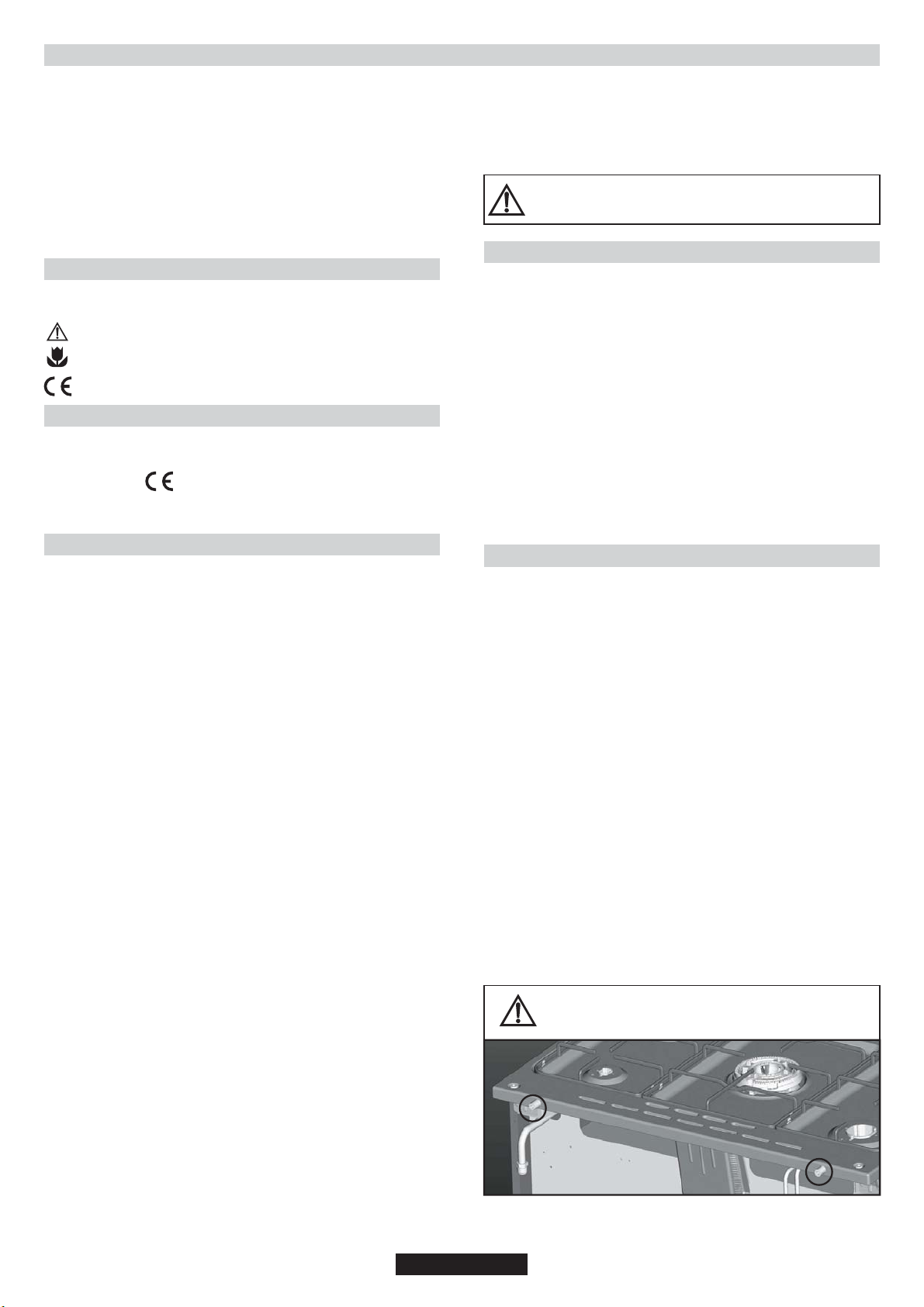
WARNING! Care must be taken regarding where the appliance is placed!
It can only be installed in a continuously ventilated room.
Electrical connections must always be disconnected before any repair,
installation or modification.
The use of a gas cooking appliance results in the production of heat and
moisture in the room in which it is installed. Ensure that the kitchen is well
ventilated: keep natural ventilation holes open or install a mechanical
ventilation device (mechanical extractor hood). Prolonged intensive use
of the appliance may call for additional ventilation, for example opening of
a window, or more effective ventilation, for example increasing the level of
mechanical ventilation where present.
•Before positioning your appliance, check the properties of the energy
supply (gas type, gas pressure) and make sure that your appliance is
regulated accordingly.
•This appliance must not be connected to the exhaust system of any
equipment running on other fuel.
•The appliance must not be installed near flammable materials (e.g.
furniture, curtains, etc.)
•If the range is placed on a base, measures have to be taken to prevent the
appliance slipping from the base.
Before installation of cooker, plastic bumpers
must be fixed at rear surface of burner plate.
04 GB
Page 5
2.1. ENVIRONMENT THE APPLIANCE
SHOULD BE PLACED
•The appliance must not be placed on a base
•There must be sufficient natural air ventilation in the room for gas
combustion for the appliance to function correctly.
•The air flow should enter through grilled air vents in the outer walls.
•Air grills must have a cross section of 100 cm² for the passage of air and
for appliances with a flame safety device. For appliances with no flame
safety device, this cross section should be 200 cm². (Single or multiple
grills can be used)
Emission of Combustion Gases
•Combustion gases from cooking appliances must be released directly out
of doors or via a hood connected to a chimney or flue (Figure 1)
•If it is impossible to install a hood, an electric extraction fan should be fitted
in a wall or a window opening out of doors (Figure 2)
•Extractor fans should have a capacity of replacing kitchen air 3- 5 times
per hour.
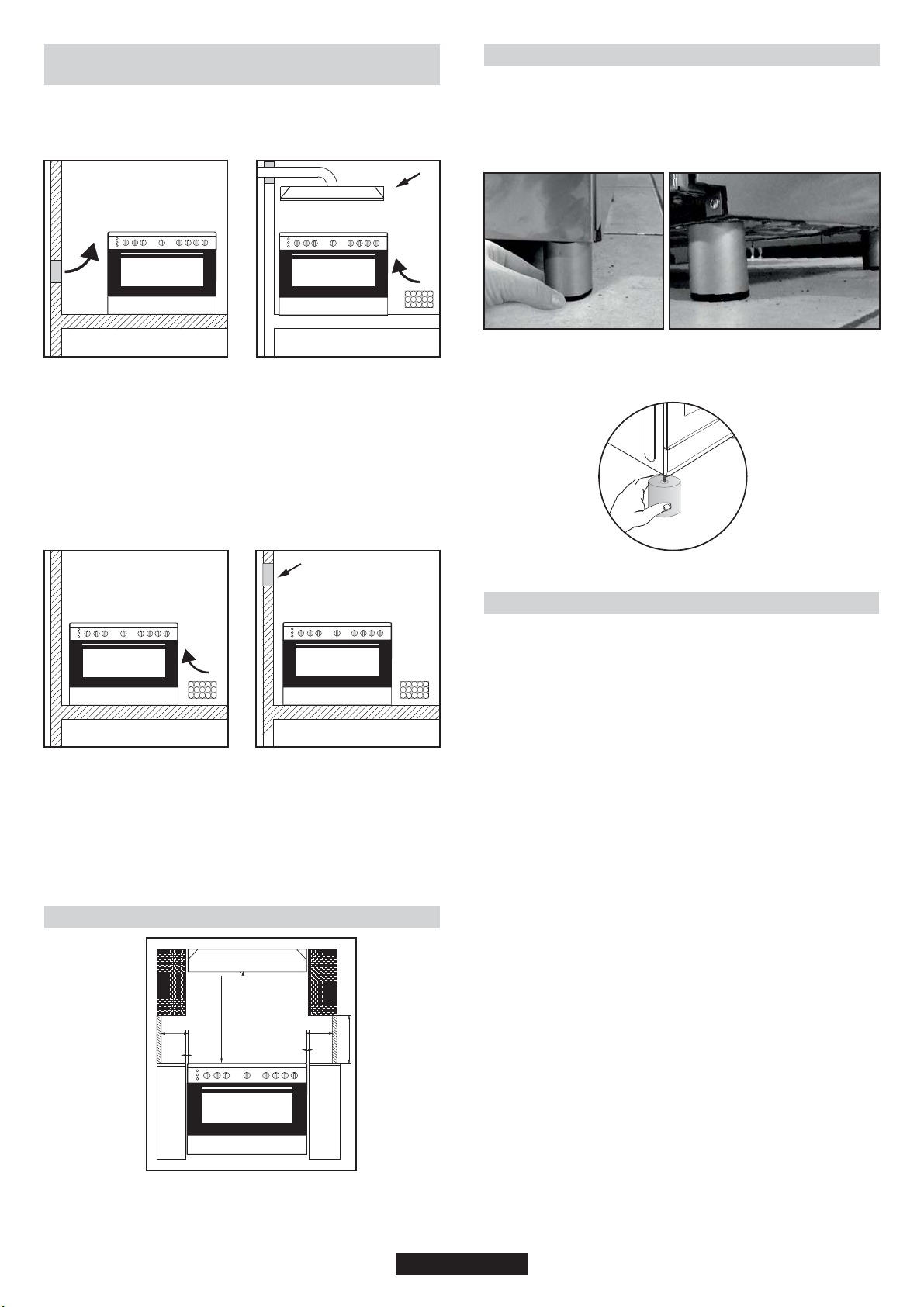
2.3. FEET ADJUSTMENT
Your appliance has adjustable feet at the lower corners of its chassis.
•The feet can be adjusted individually with the aid of a wrench to
guarantee that the oven is perfectly balanced and levelled, so that any
liquids in the pans is horizontal .
•The maximum height of cooker will be 920mm by fixing the adjustable
feet.
Figure 1 Figure 2
•This grill(s) should be constructed so that it cannot be closed from
either side and positioned preferably near the floor. Grill(s) must not be
placed across the channels through which combustion gases and
exhausted fumes pass.
•If it is impossible to install grilled air vents in the room where the
appliance is installed, the air needed can also be supplied from an
adjacent room providing it is not a bedroom or a room where an air
current could cause danger.
2.2. POSITIONING
20 mm
750 mm
20 mm
400 mm
200 mm 200 mm
This appliance is “Class 2.1”. The appliance has been designed on
the presumption that the adjacent work tops will be no higher than the
cook top surface.
2.4. ELECTRICAL CONNECTION
Cookers can be presented with or without enrgy cable. Cable
connection should be done by Autorited service according to
following instructions.
The electrical connection must be made according to the standards
and regulations in force. Before making the electrical connection,
check the following:
•Is the capacity of the electrical connections and safety fuses in the
building sufficient to cope with the load of the appliance? (Check with
the adhesive info label)
•Does the electricity supply line have an earth connection conforming
with the standards in force? A proper earth connection must exist in
your home. If there is not a proper earth connection at your home,
please apply to an authorized technician to deal with this problem.
•Is the socket or the multi-pole switch at a easily reachable point after
the installation of the appliance?
•A plug conforming to standards should be connected to the mains
cable and the cable should be inserted into a safe socket.
•A multi-pole switch must be used between the appliance and the
electricity line if a direct electrical connection to the appliance is
required. (It must comply with standards and be appropriate for the
load)
The green-yellow ground cable must not be interrupted by a switch.
The brown phase cable (from the “L" coded connector of the oven)
must always be connected to the phase line of the mains.
•The power line must be positioned so that it is not exposed to
temperatures higher than 50° C.
•When the power cable must be changed, a cable with a cross section
appropriate to the indicated power must be used. The green-yellow
ground cable should be approximately 2 cm longer than phase and
neutral cables.
•Check the heaters by switching them on for 3 minutes, after having
completed the connection.
•The manufacturer will not accept responsibility for damages
arising due to non-compliance with the safety standards.
•For the direct connection to the fixed wiring, it’s nessessary to provide
means for disconnection from the supply mains having a contact
separation in all poles that provide full disconnection under
overvoltage category III conditions, in accordance with the wiring
rules
05 GB
Page 6
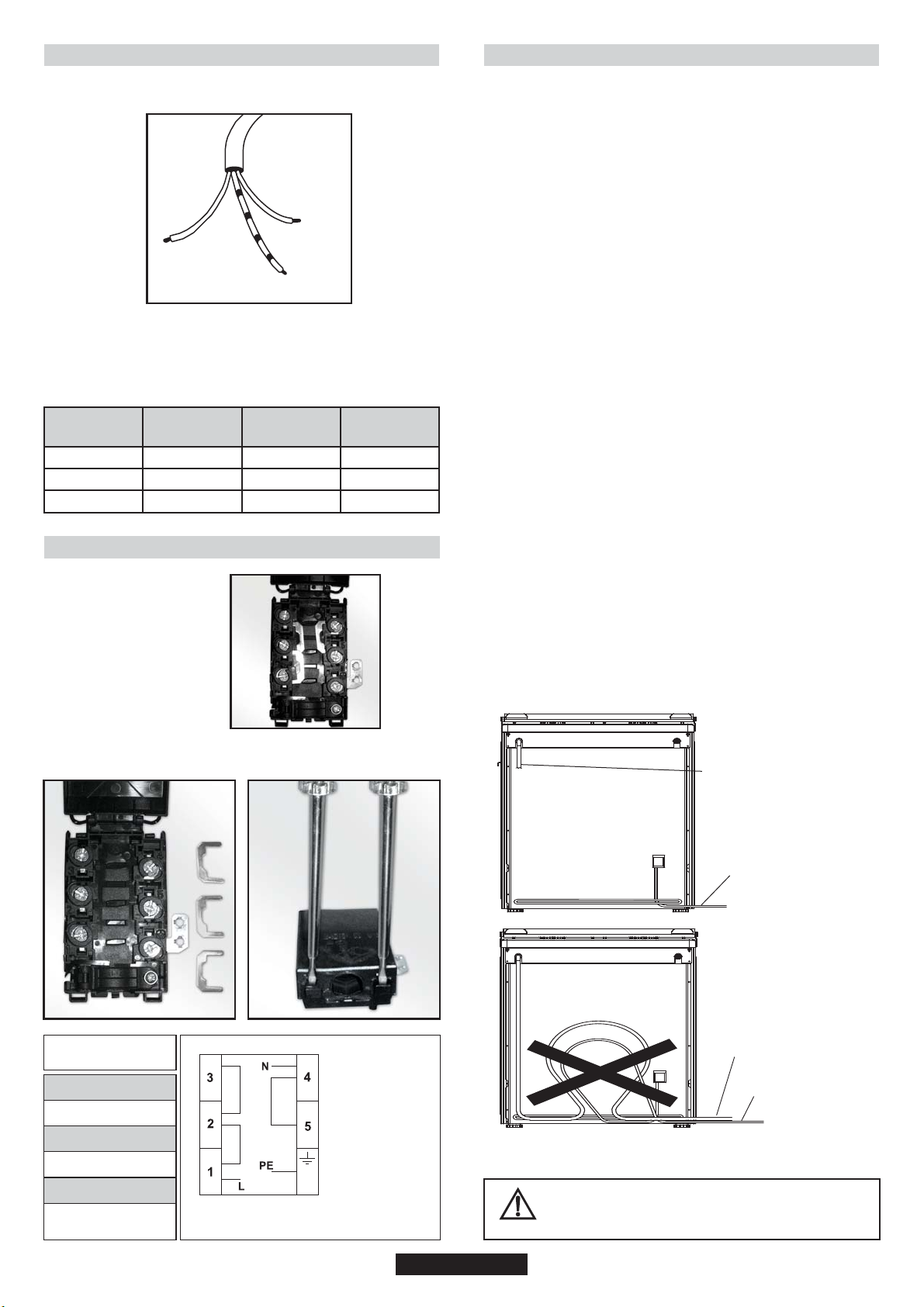
2.5. COOKERS WITH ENERGY CABLE
•Connection is exclusively envisaged under tensions of 220-240V
Between phases or between phases and neutral.
Neutral
Phase cable
(brown)
Ground cable (Green-Yellow)
•The eventual replacement of the supply cord must be carried on by
the After Sales Service or by an agreed engineer, with a cord whose
characteristics must be similar to the original one
(blue)
2.7. GAS CONNECTION
The gas must be connected to the appliance according to standard
and the provisions in force.
•When the appliance left the factory, it was regulated for the gas type
stated on the adhesive info label near the gas inlet at the back of the
appliance.
Make sure that you are using the gas stated on the label. If it is a
different type of gas, follow the instructions in the chapter on
conversion to different gas types'.
•Make sure that gas supply pressure is that given in the gas type
category table (Last page in this user manual) in order to achieve
maximum efficiency and lowest consumption. If the gas pressure is
different, a proper gas regulator should be used on the gas inlet. The
use of a gas regulator complying with the standards for LPG is
allowed.
Connection with a Solid or Flexible Metal Pipe
•The gas supply can be connected by a proper flexible stainless steel
pipe according to the safety standards in force. In this case, there will
be no further need to move the appliance. The gas inlet connector of
the appliance is Gc ½.
Ratings/Supply Cable Sections:
Model rated
power (kW)
0.025 kW
2.5 kW
6.4 kW
2.6. COOKERS WITHOUT ENERGY CABLE
Rated Voltage
(V)
220 - 240 V
220 - 240 V
220 - 240 V
Cable box connection types
Rated Current
(A)
0.01 A
11.4 A
28 A
Supply Cable
3 x 0.75 mm
3 x 1.5 mm
3 x 4 mm
1- Monophase connection
Attention: A poor clamping can draw away risks dangerous
heating at the level of the cable feeding
Connection with a Flexible Non-metallic Pipe
•If the gas connection is in a position where it can be switched on and
off when required, a flexible pipe complying with the standards in force
can be used. The flexible pipe must be firmly fixed with a clamp.
2
2
2
•The flexible pipe can be connected as follows:
•Since the flexible pipe will be placed behind the oven, it should be
exposed to temperatures no higher than 30ºC at any point.
•The length should be no longer than 150 cm.
•It must not be exposed to steam.
•No folding, bending or tension is allowed.
•It should be protected against sharp or piercing objects.
•It must be accessible in order to allow for periodic inspection.
•The flexible pipe must be checked as follows to guard against wear
over time:
•Check that there are no cracks, cuts or burned spots on or at the ends
of the pipe.
•The material must maintain its flexibility . Excessive rigidity is not
allowed.
•There must be no rust on the clamps.
•It should be replaced in any case after no more than 5 years' usage.
RIGHT
FLEXIBLE GAS PIPE LINE
Monophase
220-240 V~
32 A
3 G 4 mm
2
H05VV-F / H05RR-F
L1 : Phase
shunt 1-2 and
shunt 2-3
N : Neutral
shunt 4-5
PE Earth
ELECTRICAL CABLE
WRONG
FLEXIBLE GAS PIPE LINE
ELECTRICAL CABLE
Check all connections for leaks with a soapy substance
after the installation is completed. Do not use a flame
for to check gas leaks.
06 GB
Page 7
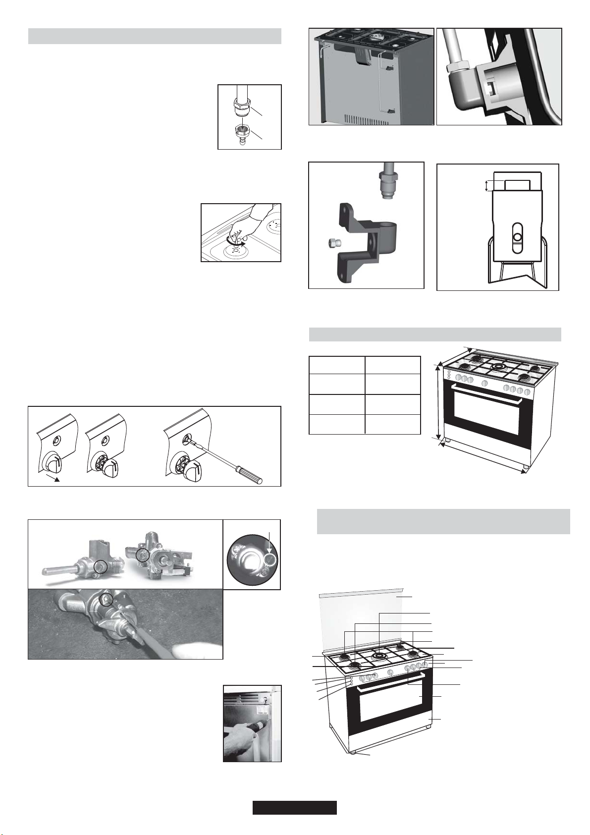
2.8. CONVERSION FOR DIFFERENT GAS TYPES
For the cookers below written adjustment have to be done by qualified
technician.
Follow the steps given below to convert the appliance from the factory
set up to that for a different gas type.
Cookers are adjusted NG and connection type is
cylindric (1).
For LPG connection, LPG hose adapter (2) can be
fixed to cylindric adapter with seal.
Adjustments and changing injectors
Changing Injectors
•Remove grates.
•Remove burner caps and burners.
•Remove injectors by using a 7 mm wrench, then screw on the correct
injector selected from gas type category table (last page in this user
manual) according to the gas to be used.
•Follow the above steps in the reverse order
after completing the assembly of the new
injector.
Stand by Adjustment
Stand by adjustment for the cookers
without safety devices and with safety
devices and button ingition
•Turn the burner control knob to the small flame
position and remove the knob.
•If conversion from natural gas to LPG is required, turn clockwise the
by-pass screw of the gas valves with a screw driver to their final
position.
•If conversion from LPG to natural gas is required, turn anti-clockwise
the by-pass screw of the gas valves with a screw driver till a smaller
flame of ¼ size is obtained.
•After completing the adjustment, insert the knobs again.
•Check the adjustment by turning the burner control knob quickly from
maximum to minimum position. If the flame does not go out, it means
that the adjustment is correct.
•For safety devices, idle flame setting can be done with screw on valve
body. If there is ignition on the knob for idle flame setting cooktop,
toplid and panel must be removed.
1
2
Burner Gap
LPG 5mm
NG 10 mm
Figure5
2.9. DIMENSIONS OF THE APPLIANCE
D
90 x 60
Height (mm)
(Toplid closed)
Width (mm)
900-920
900
H
Figure4
Figure6
without safety
devices
•For thermostat valve idle frame setting cooktop, top lid and panel
must be removed.
By-pass screw for the burner
safety devices
Gas Oven
•Remove rear cover ( Figure3)
•Remove injector adapter.(Figure 4)
•Remove injectors by using a 7 mm wrench, then
screw on the correct injector selected from gas
type category table according to the gas to be used.
(Figure 5)
•Follow the above steps in the reverse order after
completing the assembly of the new injector.
•Burner Gap is 5 mm for LPG and 10 mm for NG.
(Figure 6)
Figure3
Depth (mm)
600
W
2.10. GENERAL APPEARANCE AND DEFINITION
OF THE APPLIANCE
This User Manual has been drawn up as a guide for several models.
Some of the properties mentioned in this manual may not exist in your
appliance.
1- Cook top
5
9
8
7
6
12
10
11
14
17
18
19
20
1
2
15
4
3
2- Control panel
3- Drawer
4- Oven door (Front door)
5- Glass top lid or metallic
top lid
6- Auxilary burner
7- Rapid burner
8- Semi rapid burner
16
9- QC
13
10- Left grate
11- Centre grate
12- Right grate
13- Burners control knobs
14-Thermostat oven knob
15- Upper oven burner, grill
16- Timer knob
17- Ignition button
18- Lamp knob
19- Turn spit
20- Bolt Foot
(Adjustable Feet)
07 GB
Page 8

5
9
8
7
6
12
10
11
14
16
17
18
19
1
15
2
13
4
3
3. USE OF COOKTOP BURNERS
3.1. USE OF COOKTOP GAS BURNERS
1- Cook top
2- Control panel
3- Drawer
4- Oven door (Front door)
5- Glass top lid or metallic
top lid
6- Auxilary burner
7- Rapid burner
8- Semi rapid burner
9- QC
10- Left grate
11- Centre grate
12- Right grate
13- Burners control knobs
14- Oven knob
15- Timer knob
16- Ignition button
17- Lamp knob
18- Turn spit
19- Bolt Foot
(Adjustable Feet)
1- Cook top
2- Control panel
3- Drawer
4- Oven door (Front door)
5- Glass top lid or metallic top lid
6- Auxilary burner
7- Rapid burner
8- Semi rapid burner
9- Rapid HP 1500W
10- Rapid HP 2000W
11- Left grate
12- Right grate
13- Burners control knobs
14- Hot plate control knobs
15-Thermostat oven knob
16- Oven grilll
17- Timer knob
18- Ignition button
19- Bolt Foo t(Adjustable Feet)
5
10
9
7
8
11
1
2
18
15
4
3
19
6
7
12
13
17
16
14
The knobs which control the burners are positioned on the control
panel.
Figure 7
Off Position
When the knob is turned so that the 'dot' symbol faces towards
the panel, it is in the Off position and the gas valve is closed and
the flame will go out.
Maximum Gas Flow
Press the burner knob and turn it to the left till the 'dot' symbol
faces towards the large flame symbol.
The flame is on full at this position.
In this position, the gas valve is completely open.
Minimum Gas Flow
The flame can be decreased by turning the knob so that the 'dot'
symbol faces towards the small flame symbol. The valve will be
partially open and the burner will then be on low.
A
A - Burner Lid
B - Burner
C - Electrode
D - Injector ( Jet )
E - Burner body
B
F - Safety device
C
Ignition of the Burners
Cooktop Gas Burners
The burner must be ignited before a pan is placed over it.
For models with automatic ignition, the 'spark' button must be
pressed.
Press the knob controlling the burner you want to ignite and then turn it
left to the big flame symbol. Press the ignition button. On models with
ignition-thru knobs, press and turn the knob controlling the burner you
want to ignite as far as the star symbol; the electrode will be
automatically activated. All the electrodes will be activated
automatically and the burner to which gas is supplied (that relative to
the knob pressed) will ignite.
Oven Gas Burners
The button must not be kept pressed down for more than 15 sec. If the
burner has not ignited after 15 sec. release the button and open the
compartment door and/or wait at least 1min. before attempting again.
For other models the gas is ignited by means of the control knobs.
Make sure that the gas is actually burning after this
step! If there is no flame, repeat the procedure
After ignition, adjust the flame to the size required.
Manual ignition (if the electricity supply is not available)
Hold a flame (a match or a lit taper or a hand-operated gas lighter),
near the burner.
WARNING! to wait 1 minute between two ignition tentative.
Press and turn the knob of the burner you want to ignite as far as the
large flame symbol. If the burner does not catch fire at the first attempt,
try again pressing the knob a little longer. When the burner is lit, adjust
the flame to the required level.
If the burner does not light after several attempts, check the correct
position of the burner and its cap.
Turn the knob clockwise to the “O” position in order to close the gas
flow. If the burner accidentally stops burning, wait at least one minute
before attempting to relight it.
Some cookers have a flame safety device (see the picture above,
safety device F). If the flame goes out, the gas supply is automatically
cut off.
F
D
E
Figure 8
Minimum and maximum diameters of the cooking pan bases :
Burner
Auxiliary Burner
Semi Rapid Burner
Rapid Burner
QC
Min. Diameter [mm]
Ø 60 mm
Ø 140 mm
Ø 220 mm
Ø 220 mm
Max. Diameter [mm]
Ø 200 mm
Ø 240 mm
Ø 280 mm
Ø 320 mm
08 GB
Page 9

•The outer surface of the flame is hotter than the inner part. The tips of
the flames must touch the bottom of the pan. Flames extending
outside the pan cause unnecessary gas consumption.
•Gas burners, unlike the electrical hot plates, do not need flat
bottomed pans. Flames touching the base of the pan conduct the heat
completely.
•Although there is no need for special pans for gas burners, pans
made of thinner material conduct the heat faster than those in thicker
material.
•Some parts of the food may be heated while others remain cold due
to the uneven distribution of heat under the pan. Therefore,
continuous stirring of the food being cooked is necessary in the case
of thin-bottomed pans. Heat is more effectively and evenly distributed
with thick-based pans.
•Use of very small pans is not recommended. Wider, low-sided pans
are more suitable for more effective and quicker cooking than small,
deep pans.
•You cannot shorten cooking time by using a small pan over a large
burner. You will only waste gas in this way. However, a pan with a lid
will save energy.
3.2. USE OF COOKTOP ELECTRICAL PLATES
Turn the knob to the position for the required temperature of the hot
plate. The indicator light of the hot plate will come on and the hot plate
will start to heat.
When cooking is completed, turn the knob to the “O” position. Do not
leave the hot plate turned on without a pan on it. The diameter and the
base of the pan you use is critical. The minimum diameter of the pan
base is 14 cm and the base should be flat.
Leave the hot plate to heat up for 5 minutes before placing a pan on it
the first time you use it. This will allow the heat resistant coating of the
plate to harden due to burning.
Use a wet cloth and detergent for cleaning the hot plates. Do not
remove food residues from the hot plates with a knife or any other
hard, sharp object.
Turn on the hot plate for a few moments to dry it after cleaning.
However, it must never be left on for more than a few moments without
a pan on top.
1
2
3
Figure 9 Figure 10
Position
0
1
2
3
4
5
6
Power
(Watt)
0
100 W
180 W
250 W
500 W
750 W
1000 W
Power
(Watt)
0
135 W
220 W
300 W
850 W
1150 W
1500 W
Power
(Watt)
0
175 W
220 W
300 W
850 W
1150 W
2000 W
Explanation
Off
Heating
Cooking at low temperature
Cooking at low temperature
Cooking, Roasting, Boiling
Cooking, Roasting, Boiling
Cooking, Roasting, Boiling
Suitability of Cooking Pans
Keep in mind that larger pans have larger heating surfaces.
This will help them to cook the food faster than pans with smaller
heating surfaces.
Always use pan sizes proportionate to the amount of the food to be
cooked. In order to prevent splashing, do not use very small pans,
especially for foods with excess liquid. If you use excessively large
pans for quick cooked foods, sausages and liquids will stick and
residues will remain attached to the pan after being emptied.
Closed pans and baking trays or moulds are suggested for cooking
sweets. Splashed sugar and juices from an open pan may stick to the
cooker surface and will be difficult to remove.
6
5
4
Figure 11
Figure 12
This is especially important for pans used for roasting or pressurized
cooking at high temperature.
Do not leave burners unattended without a pan or with an empty pan
on top.
Check the suitability of cooking pans with respect to the following
criteria;
They should be heavy.
They should completely cover the burner surface; they may be a little
bigger but no smaller.
Base surfaces should be completely flat and fit well on the cooking
surface.
•For the best use of the electric hotplates and to minimize energy
consumption, only pans with smooth flat bases should be used. The
size of the pan should be as close as possible to the diameter of the
hotplate, and never smaller. The base of the pan should be dry and
spillage should be avoided. Empty pans must not be left on the plates,
and the plates should not be left switched on without a pan.
4. USE OF THE OVEN
4.1. GRILLING
•Grilling gives food a rich brown colour quickly. Depending on the
quantity of the food, you can switch the grill on to different positions.
Almost all food can be cooked under the grill except for very lean game
and meat rolls.
•Meat and fish that is going to be grilled should first be lightly doused
with oil.
•Place a fat collecting tray beneath during grilling. Put some water into
the tray to prevent unpleasant smells and to prevent the fat catching
fire.
•Grilling is usually preferred for cooking pieces of meat, for example
steaks, which are not too thick, different sized meat parts, cleaved
hunted birds, fish, some vegetables (e.g. courgettes, aubergines,
tomatoes, etc.) together with meat and fish products on spits.
Oil the fish lightly before putting it directly under the grill.
Add salt on meat after cooking, salt fish into the cleavage before
cooking.
•The distance from the grill will depend on the thickness of the meat or
fish. If the distance is correctly judged, the outer parts will not be burnt
and the inside will not remain raw.
•Prevent unpleasant odours and smoke caused by dripping fats and
sauces by pouring 1-2 glass of water into the fat-collecting tray.
•You can also use the grill for toasting, toasted bread or sandwiches,
for example, and also to cook certain fruits (bananas, grapefruit or
pineapple slices, apples etc.). However, fruit must not come into
contact with the heating elements.
When grill function is selected, the oven temperature must
be adjusted up to 200ºC (max), in case there is an
installed termostat on your product.
Never cover oven inner walls or the bottom with
aluminium foil. Accumulated heat can damage the oven
enamel and your meal.
While the oven functions are running, top lid of the
cooktop must be open position.
Oven door must be closed in grill position.
09 GB
Page 10

4.2. ELECTRIC OVEN
4.6. COOKING FISH
Position
Function
Temperature
Cooking time
Not in function
Turn spit and grill heater
Lamp
Grill heater (Electric or gas)
Lower gas burner
Lower and upper heating element
Upper heating element
Lower heating element
Lower and upper heating element
Manual
Oven Function
4.3. ELECTRIC OVEN SUGGESTIONS FOR
COOKING
Traditional Cooking
Heat is generated from the upper and lower heaters. Generally, the
middle shelf position is preferable for cooking. However, if the top or
bottom surface of the food must be cooked more, place it on the upper
or lower shelf.
Small fish can be cooked at the maximum temperature from start to
finish. Medium sized fish must be cooked at the maximum
temperature at the beginning and then the temperature must be slowly
reduced. Larger fish must be cooked at lower temperatures from start
to finish. Check the cut at the bottom of fish to understand whether it is
cooked properly. In order to understand whether the fish properly
grilled or not, check the cleavage at the bottom of the fish. The colour
(for grilled fish) should be an even matt white. This is not the case for
salmon and trout.
4.7. COOKING TURN SPIT
•The cooker is equipped with a metal turnspit, two forks and a hook
used to support the spit.
•Instruction for use:
-Remove all accessories from the oven;
-put the deep pan on the bottom of the oven or on the lowest bench;
-stick the turnspit through the meat, centered between the two forks;
-Fix the turnspit into the drive hole located in the left side wall, then
hang the support hook in the drive located at the right side of the oven
cavity and around the edge of the turnspit.
•Preheating is not necessary with the turnspit.
•Cooking Time Recommended in turnspit Position.
Cooking time (min)
Type of food
Beef (1kg)
Lamb, sheep (1kg)
Veal, Poultry (1kg)
Gas Oven
25/35
35/45
65/75
Electric oven
20/30
30/40
60/70
4.8. USING THE MINUTE TIMER
4.4. COOKING CAKES
•Unless otherwise suggested, preheat the oven for at least 10 minutes
before use. Do not open the oven door when cooking cakes otherwise
they will not rise (cakes or dishes with yeast and soufflés). The blast of
cold air which will enter the oven will prevent rising. You can check
whether cakes are properly cooked by inserting a rod into the dough. If
the rod comes out dry when you pull it out, it means that the cake is
properly cooked. Do not check in this way until at least three quarters
of the cooking time has elapsed.
Please keep in mind the following tips
•If the surface of the food is cooked well but it is still raw or partly raw
inside, it must be cooked longer at a lower temperature.
•On the other hand, if the surface of the food is too dry, it should be
cooked at a higher temperature for a shorter time.
4.5. COOKING MEATS
•The minimum quantity of meat to be cooked in the oven is 1 kg.
Otherwise, the meat will be too dry.
If you require well done meat, use less fat. If meat has a little fat, there
is no need to use oil. If one side of the meat is fatty, place this side up.
The melted fat will sufficiently grease the part below. Red meats
should be taken out of the fridge at least 1 hour before the cooking.
•Otherwise the meat may become tough due to the temperature
difference. Do not use salt before cooking, especially when grilling
meat. Salt will draw the blood and juices out of the meat which will
consequently prevent the roasting of the upper surface of the meat.
•Add salt to roast meat only after half of the cooking time has elapsed.
•Place the meat to be roasted in a wide, shallow pan.
•Deep sided containers / pans act as a shield against the heat. Meat
can be placed in the oven in a heat resistant pan or directly onto the
grill. Insert a fat / gravy collecting tray beneath the grill. Sauces must
be added at the beginning if the food is cooked for a short time, while it
would be better to add sauces in the last half hour if the food is cooked
for a longer time.
Figure 13
To set the cooking time, turn dial one
50
40
30
complete revolution and then position
10
the index to the required time. When the
time has lapsed, the signal will ring for a
few seconds.
20
4.9. USING THE END OF COOKING TIMER
Figure 14
90
80
70
10
50
60
This control enables to set the desired
cooking time (max. 90 min.) the oven will
automatically switch off at the end of the
set time.
The timer will count down from the set
20
time return to the “O” position and switch
off automatically.
30
For normal use of oven set the timer to
the position.
To set the oven ensure the timer is not on
40
the “O” position.
10 GB
Page 11

4.10. GAS OVEN
Figure 15
The oven temperature and heater can be
selected by turning the oven adjustment
knob to the desired temperature level.
The oven thermostat range is: 140250°C.
Min
Some cookers have flame safety device
on burners. If the flame goes out, the gas
supply is automatically cut off.
Max
230
180
200
4.11. COOKING TABLES
Traditional Cooking Methods; Weights (gr)
TYPE OF THE FOOD Traditional Cooking Method
Weight
(Gr)
1000
500
500
TYPE OF THE FOOD
CAKES AND
DESSERTS
Dough with stirred egg
Dough
Small Cakes
Cheese Cake
Apple Pie
Strudel
Jam tart
Small cakes
Biscuits
Cream cakes
BREAD AND PIZZA
White Bread
Rye Bread
Sandwich
PASTRY
Macaroni
With vegetable
Small pastries
Lasagne
Traditional
Cooking
Method
Shelf
Position
2
1
2
1
1
2
2
2
2
2
1
1
2
2
2
2
2
Tempera-
ture (°C)
180
180
180
175
180
175
180
180
180
100
200
200
200
200
200
200
200
Cooking
times
(Minutes)
45 - 60
20 - 35
20 - 30
60 - 80
40 - 60
60 - 80
45 - 60
15 - 25
10 - 20
90 - 120
45 ~ 60
30 ~ 45
20 ~ 35
40 ~ 50
45 ~ 60
35 ~ 45
45 ~ 60
N O T E S
Inside the
closed oven on
dishes 8 pieces
on a tray
Under the grill
Shelf Positions
3
2
1
Figure 16
NOTE :
1) Cooking times do not include pre heating. Preheating the oven
for about 10 minutes is advisable especially for cakes, pizzas and
breads.
2) Indicates tray positions for cooking several dishes
simultaneously.
3) All cooking operations must be carried out with oven door
closed.
MEATS
Roast beef
1000
Roast veal
1000
British style roast beef
1500
Lamb
1200
Chicken
1000
Turkey
4000
Duck
1500
Goose
3000
Rabbit
1200
FISH
Whole fish
1000
Fillet
800
2
2
2
2
2
2
2
2
2
2
2
200
200
200
200
200
200
175
175
200
200
200
50 ~ 70
90 ~ 120
50 ~ 70
110 ~ 130
60 ~ 80
210 ~ 240
120 ~ 150
150 ~ 200
60 ~ 80
40 ~ 60
30 ~ 40
Cook on grill
Cook on grill
Cook on grill
Leg
Full size
Full size
Full size
Full size
In parts
2 Fishes
4 Fillets
FOOD TYPES
Beefsteak
Grilled cutlet
Sausage
Chicken parts
Mixed grill
Milky desserts
Tomato slices
Fish fillets
Scallops
Toast
Bread slices
QUANTITY COOKING ON GRILL
3
3
3
3
3
3
3
3
3
3
3
TEMPERA-
TURE (°C)
N. OF
PARTS
4
4
8
6
4
4
8
4
6
4
4
WEIGHT
800
600
500
800
700
400
500
400
---
--—
SHELF
POSITION
max
max
max
max
max
max
max
max
max
max
max
COOKING TIMES
(Minutes)
UPPER
SECTION
SECTION
10
12
10
30
12
13
12
8
12
8
2-3
LOWER
8
8
6
20
10
10
-6
--
-1
11 GB
Page 12

5. CLEANING AND MAINTENANCE
Before all cleaning and maintenance :
•Disconnect mains voltage.
•Shut off the gas valve for your own safety. If the oven is adjusted to
natural gas, shut off the natural gas valve.
•If the oven is hot, wait till it has cooled down.
•Never use abrasive cleaners, wire wool or sharp objects to clean the
glass oven door.
•Clean enamelled surfaces with warm, soapy water or with suitable
brand products. On no account use abrasive powders that may
damage surfaces and ruin the appearance of the cooker.
It is very important to clean the oven each time it is used.
•Use detergents and abrasive metal pads for the stainless steel grills.
•The glass surfaces such as the top, the oven door and the warming
compartment door must be cleaned when they are cold.
•Damage caused by failure to respect this rule is not covered by the
guarantee.
•You can clean burners and burner caps with hot water and detergent.
Also the gas channels of the burners can be cleaned by a brush. Make
sure that burners are dry before replacing them in their seats. Check
correct positioning of the burner.
especially for cakes, pizzas and breads.
•Periodically clean the ignition electrodes of automatic ignition ovens.
This will prevent ignition problems. Check frequently that
the gas channels of burners are not blocked by food residues, etc.
•Wipe the top lid with a dry cloth in order to prevent harmful effects of
water, oil and steam generated by the cooked food.
•Do not use abrasive products, metal cleaning pads, sharp objects,
rough cloths, or chemical products and detergents that can
permanently damage the catalytic lining.
•It is a good idea to use deep roasting trays for fatty foods such as
joints of meat etc. and to put a tray underneath the grill to catch surplus
fat.
6. SERVICE CENTRE & TROUBLESHOOTING
•If the oven is not working, before calling the service centre we
recommended that :
•You should check that the oven is properly plugged into the power
supply.
Gas input is abnormal
•Check the following:
•Are the holes of the burner clogged?
•Is the pressure regulator working properly?
•If you are using a pipe, is there any gas in the pipe? Is the valve open?
•If you detect something abnormal with the gas valves, contact a
qualified electrician or an authorised service centre for assistance.
There is a smell of gas where the appliance is placed
•Please check the following:
•Has a gas valve been left open?
•Is the gas pipe in the correct position and in good condition?
If you suspect a gas leak, do not use a flame to check
The oven does not heat up
Are the oven control knobs at the correct position ?
The cooking time is too long
Has the correct temperature been selected ?
Smoke comes from the oven
It is advisable to clean the oven after each use. If fat which splashes
during the cooking of meat is not cleaned, it will cause an unpleasant
smell and smoke the next time you use the oven. (See the Cleaning
and Maintenance chapter)
The oven light does not come on
•The light might be faulty. To change the bulb, please see the relative
page.
•If you have checked the above and the oven still does not work
properly, contact the nearest authorized service for assistance
• Model and Production Number (PNC or ENR).
Cleaning of Oven Door
For thorough cleaning of the oven door, it is advisable to remove the
same, as shown in below.
Open the door completely, turn the two feet on the hinge arms 180º.
Close the door partly by a 30º. Remove the door by slightly lifting the it
at this position.
For replacing the door, follow the steps above in the reverse order.
0
180
Figure 16
To Replace the inside light
•Switch off the mains power supply and unscrew bulb.
Replace with an identical bulb that can withstand very high
temperatures.
Figure 17
7. PROTECTION OF THE ENVIRONMENT
This appliance is marked according to the European
directive 2012/19/EU on Waste Electrical and
Electronic Equipment (WEEE). WEEE contains both
polluting substances (which can cause negative
consequences for the environment) and basic
components (which can be re-used). It is important to
have WEEE subjected to specific treatments, in order
recover and recycle all materials.
Individuals can play an important role in ensuring that WEEE does not
become an environmental issue; it is essential to follow some basic
rules:
• WEEE shall not be treated as household waste.
• WEEE shall be handed over to the relevant collection points
managed by the municipality or by registered companies. In many
countries, for large WEEE, home collection could be present.
• When you buy a new appliance, the old one may be returned to the
retailer who has to collect it free of charge on a one-to-one basis, as
long as the equipment is of equivalent type and has the same
functions as the supplied equipment.
to remove and dispose properly all pollutants, and
8. GAS TYPE
INJ. DIAMETER (1/100)mm
12 GB
BURNER
AUX
SR
R
QC
OVEN
GRILL
LIQUID GAS
G30/G31 25-30 mbar
50
65
85
100
93
71
NATURAL GAS
G20 / 20 mbar
83
100
120
145
145
110
POWER
(kw)
1.0
1.7
2.7
4.0
3.8
2.4
Page 13

Page 14

16
3
2
1
3
3
3
3
3
3
3
3
3
3
3
11
Page 15

Page 16

11
12
9 10
1
2
3
6
5
4
ﻰﺗﺣﻧﺭﻔﻟﺍﺓﺭﺍﺭﺣﻁﺑﺿﺑﺟﻳ،ءﺍﻭﺷﻟﺍﺔﻔﻳﻅﻭﺭﺎﻳﺗﺧﺍﺩﻧﻋ 200º ﺱﻭﻳﺯﻠﻳﺳ (ﺔﻳﻭﺋﻣﺔﺟﺭﺩ)
(ﻰﺻﻗﺃﺩﺣﻛ)،ﺕﺎﺗﺳﻭﻣﺭﺗﻛﺎﻧﻬﻧﺎﻛﺍﺫﺇ (ﺓﺭﺍﺭﺣﻟﺎﻁﺑﺎﺿ) ﻙﺑﺻﺎﺧﻟﺎﺟﺗﻧﻣﻟﺎﯩﻠﻌﺗﺑﺛﻣ.
ﻲﻓ ﺩﻗﻭﻣﻟﺍ ﺢﻁﺳ ءﻭﺿ ﻥﻭﻛﻳ ﻥﺃ ﺏﺟﻳ ،ﻥﺭﻔﻟﺍ ﻑﺋﺎﻅﻭ ﻝﻳﻐﺷﺗ ﺩﻧﻋ
. ﻝﻳﻐﺷﺗﻟﺍ ﺔﻳﻌﺿﻭ
ءﺍﻭﺷﻟﺎﻌﺿﻭءﺎﻧﺛﺄﻧﺭﻔﻟﺎﺑﺎﺑﻗﻼﻏﺈﺑﺟﻳ.
09
Page 17

7
A
200
240
280
320
60
140
220
220
QC
B
C
F
D
E
8
08
Page 18

ءﺍﻭﺷﻟﺍ ﺦﻳﺳ
ﻥﺭﻔﻟﺍﺩﻗﻭﻣﺓﻭﺟﻓ 5 ـﻟﺔﺑﺳﻧﻟﺎﺑﻣﻠﻣ LPG (ﻝﺎﺳﻣﻟﺎﻳﻟﻭﺭﺗﺑﻟﺍﺯﺎﻐﻟﺍ)
ﻭ10 ـﻟﺔﺑﺳﻧﻟﺎﺑﻣﻠﻣ NG (ﻲﻌﻳﺑﻁﻟﺍﺯﺎﻐﻟﺍ)
5
9
8
7
6
12
10
11
14
16
17
18
1
15
2
13
4
3
ﺽﺑﻘﻣ ﻥﺭﻔﻟﺍ
ﺩﻗﻭﻣﻟﺍ ﺔﺣﺗﻓ
LPG 5mm
NG 10 mm
ءﺍﻭﺷﻟﺍ ﺦﻳﺳ
19
D
H
5
10
9
7
8
11
1
2
18
15
4
3
19
6
7
12
13
17
16
14
W
Page 19

2
Page 20

6/2
05
0.75 x 3
1.5 x 3
4 x 3
0.01
11.4
28
220
240
220
240
220
240
0.025
2.5
6.4
Page 21

ﻭﻠﻧﻣﻳﻔﻠﺧﻟﺎﺣﻁﺳﻟﺎﯩﻠﻋﺔﻳﻛﻳﺗﺳﻼﺑﻟﺎﺗﺎﻣﺎﻋﺩﻟﺎﺗﻳﺑﺛﺗﺑﺟﻳ،ﻥﺭﻔﻟﺎﺑﻳﻛﺭﺗﻠﺑﻗ
ﻥﺭﻔﻟﺍﺩﻗﻭﻣﺔﺣ.
Page 22

Page 23

Page 24

GB
The manufacturer will not be responsible for any inaccuracy resulting from printing or transcript errors contained in this brochure. We reserve the right
to carry out modifications to products as required, including ht e interests of con sumption, without prejudice to the characteri stics relating to safety or
function.
03.2016 • REV:C • 42810235
 Loading...