

Page 1
INSTRUCTION MANUAL FOR CHIMNEY HOODS
HOTTE GUIDE D’UTILISATION
د ﻞﯿﻟاﺎﻤﯿﻠﻌﺘﻟ تﺪﺨﺘﺳﻻا ماﺔﻨﺧﺪﻤﻟ
Page 2
1
THE DEVICE IS PRODUCED AS EARTHED.
DO NOT USE IT WITH UNEARTHED PLUG.
SCOPE OF INSTRUCTION MANUΑL
Dear Customer,
In the sections provided herein, there is necessary information which will enable you to use the
device efficiently and safely. Please, read these instructions carefully before installation of the
device
Section 1 Important points which must be observed before using the chimney
Section 2 Technical specifications of the chimney hood.
Section 3 Technical dimensions of the chimney hood
Section 4 Electrical diagram of the chimney hood.
EN
Section 5 Information about installation connection of the chimney hood.
Section 6 Information about use of the chimney hood.
Section 7 Information about maintenance of the chimney hood.
IMPORTANT PRECAUTIONS AND POINTS WHICH MUST BE OBSERVED
Section 1
1. The electrical and installation connections must be done by the service staff who is wellinformed of the subject;
2. The operating voltage is 220 – 240 Volts. Do not operate the device in lower or higher
voltage.
3. Do not connect to the chimneys where the heating stove is connected, to the gas flue or to
the chimneys where the fire rises.
4. Plug the product into the socket where there is an earthed connection.
5. Fire catching food should not be cooked under the device.
6. Do not use other materials instead of aluminum filter in the device.
7. Do not plug into the socket without completion of the installation of the device.
8. Do not run the device without aluminum filter.
9. Do not touch the bulb of the device when it is left on for a long time..
Page 3

2
10. Do not remove the aluminum filter when the device is running.
11. Do not turn off the device directly by plugging it out when it is running. Turn it off from
control panel.
12. The device should be cleaned periodically..
13. The height between the lower surface of the chimney hood and oven must be 65 cm for
electrical ovens, and 75 cm for gas-fired or mix ovens
14. Keep the packaging material away from the children because they may be dangerous for
them.
15. Run the chimney hood after the kettle or frying pan is put on the oven.
16. Run the chimney hood for 15 minutes more after the operation of cooking or frying is
finished in order to clean the air of the kitchen off the smell and vapor which appeared
during cooking..
17. Let some fresh air into environment when the chimney hood is running, especially, when it
is used in the same time with the gas-fired ovens.
18. Contact the nearest service if your device is failed to run with any reason.
19. Our Company may not be held responsible from the failures arising from use which is not
consistent with the cautions stated above.
TECHNICAL SPECIFICATIONS
Section 2
EN
1. Chimney
2. Control panel
3. Body of the chimney hood
4. Aluminum filter
5. Illumination lamp
6. Glass
Page 4

3
TECHNICAL SPECIFICATIONS OF THE CHIMNEY HOOD
LENGTH
600-900 mm
WIDTH
475 mm
HEIGHT
Min. 706 mm Max 980
mm
CONTROLLER
PUSH BUTTON
AIR SUCTION
400 m3
BULB POWER
1x2 W
MOTOR POWER
190W
TOTAL POWER
192 W
DIAMETER OF AIR OUTLET
PIPE
120 mm
SUPPLY VOLTAGE
220 – 240 V 50Hz
HECH616/4X
EN
HECH916/4X
TECHNICAL DIMENSIONS
Section 3
Note: All dimensions are in mm.
Page 5

4
EN
ELECTRICAL CONNECTION DIAGRAM
Section 4
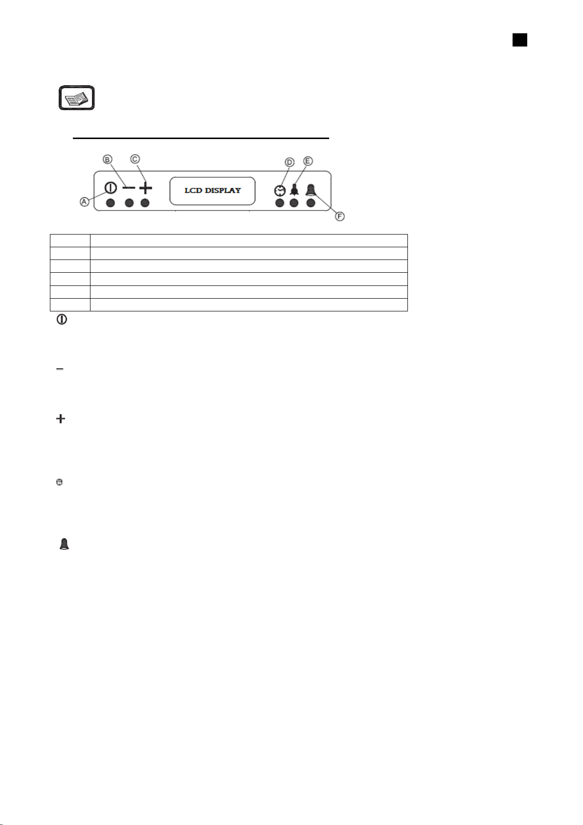
Digital Touch Button Push Button
LCD Screen
Page 6
5
INSTALLATION DIAGRAM
Section 5
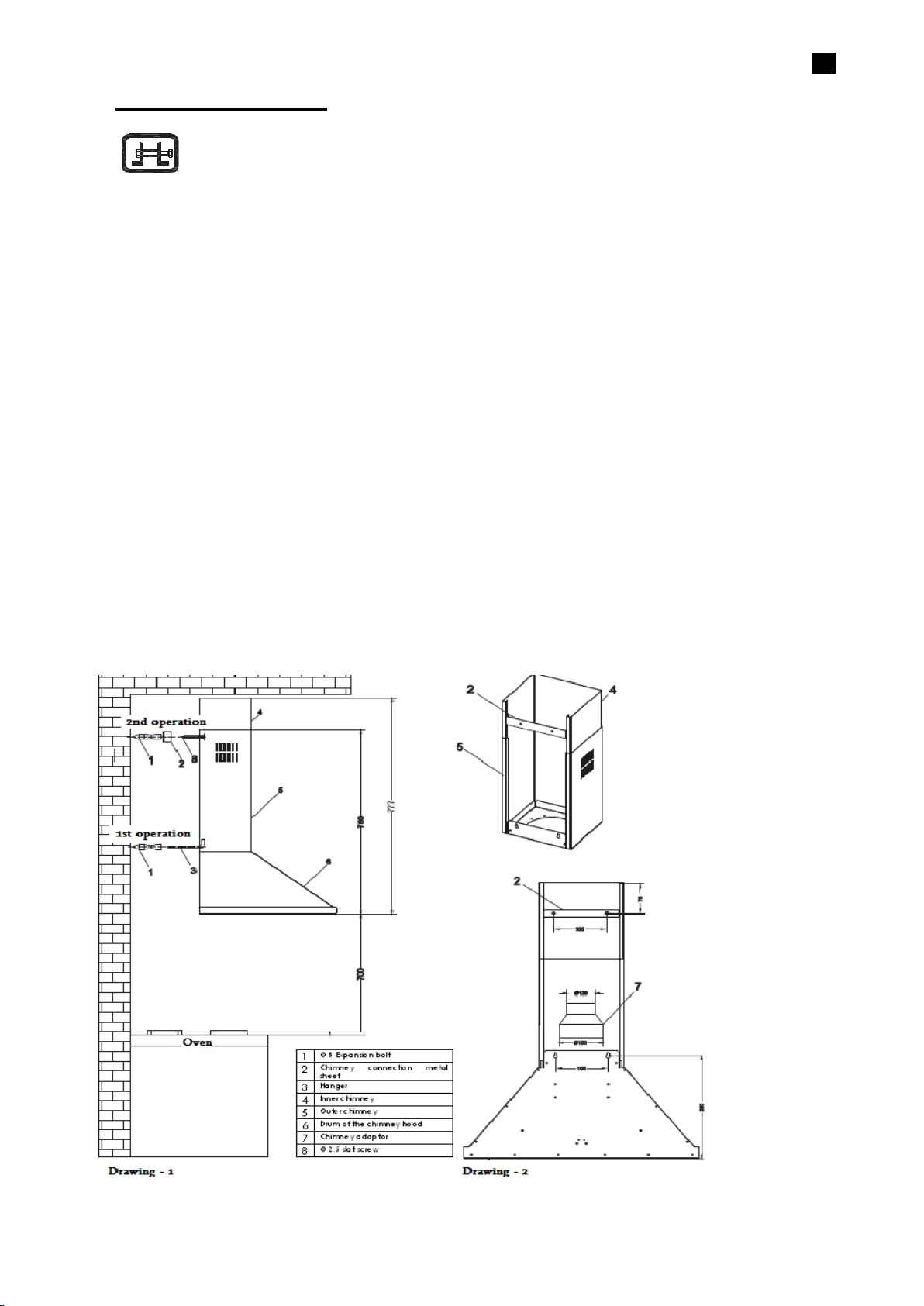
1. Draw a straight line by a measuring stick starting from the surface of the oven to 700+280:
990 mm if you want to save a space of 700 mm between the oven and the lower surface of
the chimney hood. Align the drawn line to the right and left edges. Draw a 67,5 mm axis line
from aligned center to every two sides. Make a hole by 6 mm diameter electrical drill
through two drawn points. Penetrate the expansion bolt and install the hangers.
2. Doing installation of secondary chimney of the chimney hood: draw 75 mm line from the top
surface towards the lower section. Make sure that the line is equal to right and left parts.
Draw 50 mm line each at both sides of the line and, then, make a hole through these two
lines. Penetrate an 8 mm diameter expansion bolt and tighten until 2 mm space is left inbetween of a 2,5 diameter slat screw and the expansion bolt. Later, the product is mounted
on its place and the installation will be completed by installing the inner chimney.
The operation order:
1st operation: Installation of hanger
2nd operation: Installation of chimney connection metal sheet
3rd operation: Hanging the chimney hood
4th operation: Installation of lower chimney of the chimney hood
5th operation: Installation of inner chimney
6th operation: Making electrical connection
INSTALLATION :
EN
Page 7
6
A
ON-OFF BUTTON
B
MINUS BUTTON
C
PLUS BUTTON
D
TIMER BUTTON
E
BULB BUTTON
F
ALARM BUTTON
INFORMATION ABOUT USE OF THE CHIMNEY HOOD
Section 6-1
LCD-Switch Chimney Hood Control Card Features
On/Off Button: used to start and stop the motor. In the beginning, the motor runs in 2nd
cycle. The number of cycle is represented by bar levels and the rotation speed of the fan shown at
the left-side of the display.
EN
Minus Button: the cycle of motor reduces until it reaches 1st cycle each time when it is pushed
if the motor is running. In addition, it is used to reduce the timer value. On the display, it is
represented by the number of bars and the number of rotation of the fan.
Plus Button: used to increase the cycle of motor each time when it is pushed until it
reaches the highest cycle level if the motor is running. In addition, it is used to reduce the timer
value. On the display, it is represented by the number of bars and the number of rotation of the
fan.
Shutdown Timer Button: a 15 minute starting timer value will be displayed and the clock icon
will flash for 5 times when this button is pushed while the motor is running. The clock icon will
be displayed until the timer value lapses. The motor will stop and the bulb will turn off, if it is on,
when the timer lapsed.
Alarm Timer Button: a 5 minute alarm timer will be displayed as starting timer on the
display and the bell icon will flash for 5 times when this button is pushed independent of whether or
not the motor is running. The bell icon will be displayed on the display until the timer time lapses.
The buzzer will ring for 20 seconds and the bell icon will flash when the timer lapsed. The buzzer
can be shut by pushing the alarm timer when it is ringing.
Being valid for both of them; the timer value can be adjusted to any value in-between of 1 minute
and 9 hour 59 minutes by pushing MINUS or PLUS buttons while flashing. The timer value will
increase or decrease very quickly when the MINUS or PLUS buttons are held pushed. The current
value of the timer will be displayed on the display when the timer button is pushed while the timer
is set. The started timer button is pushed one more time and it will be reduced until the timer
becomes zero by pushing MINUS button if the started timer is needed to be cancelled.
Page 8

7
Bulb Button: used to turn on and off the bulb. The bulb will appear at the right-side of the
display while it is on.
Boost Adjusting: pressing the PLUS button one more time while the motor is running with the
highest cycle will let to enter into a boost mode. In the boost mode, the motor will pass to a next
lower cycle in every 3 minute lapse and will rotate in 2nd cycle continuously by getting out from
boost mode. The TURBO icon will flash on the display while in boost mode. The boost mode will
be exited if the cycle of the motor is changed.
Filter Warning: the (CLEAN FILTER) message which expresses that the filter should be
cleaned will appear on the display when the motor runs for 60 hours. The beep sound will be heard
and the (CLEAN FILTER) message will appear for 1,5 seconds more when the M.on/off button is
held pressed for 4 seconds.
Power On: the clock which is valid when the power failure occurred will be brought on the
power on, and the operation will continue in clock adjusting mode.
Adjusting the Clock: pressing the MINUS and the PLUS button in the same moment will let to
enter into a clock adjusting mode. During clock adjustment, a triangular icon in the right midst of
the clock will flash on the display. The clock is adjusted by MINUS and PLUS buttons. The clock
adjusting mode will be exited if any other button is pushed other than MINUS and PLUS buttons.
EN
Returning to Factory Settings
A beep sound will be heard and the (Fac) message will appear on the display when the M. on/off,
MINUS and PLUS buttons are kept pushed for 4 seconds in the same moment, and the factory
settings are returned.
The Factory Settings
RGB Display Lightening Color: Red-100, Green-100, Blue-100
Display Lightening: ON
Click (the key sound): ON
Bulb Option: ON
Section 6-2
PUSH BUTTON SWITCH USING INFORMATION
The functions of the buttons are as follows:
0. Off
1. Mild ventilation
2. Medium ventilation
3. Strong ventilation
Note: While cooking food, push the buttons 1 or 2. For frying or similar meals, use 3.
Page 9

8
A
ON – OFF BUTTON
B
MINUS BUTTON
C
DIGITAL DISPLAY
D
PLUS BUTTON
E
TIMER BUTTON
F
BULB BUTTON
0 : Stop the engine
1 : Powering the first level
2 : Powering the second level
3 : Powering the third level
: On and off button of lamp
Section 6-3
INFORMATION ABOUT USE OF TOUCH-OPERATED SWITCH
EN
A – On/Off Button: used to start and stop the motor. The motor starts running in 2nd cycle
when On-Off button is pushed for the first time.
B – Minus Button: reduces the cycle of the motor.
C – Digital Display: shows in which cycle the motor is.
D – Plus Button: used to increase the cycle of the motor with one level.
E – Timer Button: when this button is pushed, the cycle of the motor flashes on digital display
and the motor stops within 15 minutes. It is necessary to keep pushed this button for 3 seconds
to activate it. Push only one time to cancel it.
F – Bulb Button: used to turn on and off the bulb.
Page 10

9
INFORMATION ABOUT MAINTENANCE
Section 7-1
Plug out the product, or turn off the power switch, or loosen or turn off the safety fuse supplying the
chimney hood, before starting maintenance operation.
Aluminum Filter
This filter is used to catch the oil particles in the air and, thus, it will be blocked after a period of
time which will change depending on the frequency of use of the device. We recommend that this
filter is cleaned once a month at most to make sure that the device does not pose a danger. For
this operation, firstly, remove the aluminum filter. Wash the filters with liquid washing agent and
flush, and mount it on its place after drying. The change in color may be observed as the aluminum
filters are washed. This is normal and there is no need to replace the filters. It is also possible to
wash the aluminum filter in the dishwashing machine.
Removing Aluminum Filter
1. Push the lock of the aluminum filter forward.
2. Then, slightly lower it downwards and push forward. Otherwise, the filter can be defected.
Wash the aluminum filter and mount it again into its place by applying the steps mentioned
above in reverse.
EN
Carbon filter (it is for flueless use)
This filter removes the cooking smell. It cleans the circulating air within the kitchen in case there is
no possibility to use chimney. Physical life of the carbon filter of the device will expire depending on
the frequency of use and mode of cooking, and that of aluminum filter will expire depending on the
cleaning regularly.
In usual use, it should be replaced once in every 4 months at most.
Removing Carbon Filter:
1. Remove the aluminum filter.
2. To remove the carbon filter, turn it to the left and pull it towards yourself.
3. Mount a new carbon filter.
4. Mount the aluminum filters.
Page 11

10
EN
Use soft cloth wetted with water to clean the exterior surface of the chimney hood. Never use
abrasive and scratching products for cleaning. The cloth must be applied in the same direction with
the brush in order to avoid scratching of the steel drum. The bulb glasses must not be removed
during cleaning.
CAUTION!
You may cause fire if you do not observe the rules pertaining to cleaning and replacing the filters of
the chimney hood.
Replacing the Bulb
There are 2 pieces of 25 W halogen bulbs on the chimney hood. First of all, plug out the product,
or turn off the power switch, or loosen or turn off the safety fuse supplying the chimney hood to
replace the bulb. Slightly press on the connecting tabs existing on the cover of the halogen bulb
with a thin tip screwdriver and push them downward. Hold the cover carefully not to let it drop down
when performing this operation. Slightly push the cover by aligning the tabs to the cavities on bulb
hole after the bulb is replaced. It is recommended that the new bulb is fixed with cloth. It is because
of fact that the life of the bulb will expire in 1 day when the halogen bulbs are touched with bare
hand.
Section 7-2
CAUTION!
Touch the bulb only when you will replace it. The life of bulb will expire after one day when the
halogen bulb is touched when it is not broken.
Firstly, disconnect the electricity of the chimney hood and dismantle it if you need it to be
transported. Carry it in its original box, if possible, and observe the transportation signs put on the
box. If no original box, make sure that the product is packed so that it would protect from any
damage.
We kindly ask you to observe following recommendations:
1. Make sure that the Warranty Certificate is endorsed by the Authorized Seller when the
product is received.
2. Use the product in accordance with the principles provided in the instructions for use.
3. Ask for the “technician identity card” from the technician who came for the technical service.
Page 12

11
Chers Utilisateurs,
Nous vous remercions pour votre choix de produit. Afin de pouvoir utiliser votre hotte en sécurité et
de manière efficace pour une longue durée, le bon montage de ce dernier est indispensable, nous
vous conseillons de lire attentivement le mode d’emploi avant son utilisation.
1) PROCEDURE A SUIVRE AVANT L’UTILISATION
1. Brancher votre hotte sur une prise de terre 220 V « LE FOURNISSERUR NE SERA EN AUCUN
CAS RESPONSABLE SI DES DEFAILLANCES SE PRESENTES EN RAISON D’UNE
MAUVAISE UTILISATION »
2. Prévoyez la sortie de la hotte au tuyau de cheminée, comme pour la connexion de la chaudière, et
le chauffe-eau.
3. Assurez vous que les boutons sur le panneau de la hotte soit en position fermée avant le
branchement de ce dernier.
4. Placer l’ampoule en ouvrant le boitier à filtre en aluminium placé sous la hotte
5. Effectuer le montage de votre hotte à l’aide du schéma fournit dans l’emballage.
6. La distance préconisée entre la plaque à trou (filtre) de votre hotte et de votre gazinière doit être
au minimum 75 cm et 65 cm pour les fours électriques.
7. Votre hotte a été conçue de manière à l’utiliser avec ou sans connexion de tuyau pour cheminée.
1)
UTILISATION AVEC TUYAU DE CHEMINEE
Sur votre hotte se trouve une sortie d’air. Les trous de sortie d’air sont de 12 cm de diamètre et sont
connectés au tuyau de cheminée à l’aide d’un tuyau en aluminium. Les précautions doivent être
prises pour les tuyaux verticaux afin d’éviter l’entrée d’eau de pluie. Dans le cas d’une défaillance
due à cette raison, la garantie de votre hotte ne sera pas valable. A cet égard, il est recommandé
d’utiliser un tuyau d’un diamètre de 120mm. Plus votre tuyau sera court et sans angle, plus votre
hotte sera efficace.
2)
UTILISATION SANS TUYAU DE CHEMINEE
Important: Si toutefois l’utilisation se fait sans tuyau de cheminée vous pouvez vous procurer un
filtre en carbone auprès de nos services compétents.
Vous pouvez remplacer le filtre par le FİLTRE EN CARBONE délivré par le service en retirant le
boitier à filtre en appuyant sur les poignées. Votre hotte est donc prête à fonctionner.
FR
Page 13

12
4) MONTAGE DE LA HOTTE
Afin de servir d’exemple, vous pouvez marquer d’un point les points de fixation avant ou arrière et
les points de fixation du tuyau de cheminée à l’ endroit où vous souhaitez monter votre hotte.
Figure 1: Vider la sortie du tuyau de cheminée. Pour la connexion supérieure utiliser 4 vis 3,5x16
YHB pour le montage de la hotte sur le placard de cuisine.
Enfoncer les 2 chevilles de 8 mm fournis au mur en forant à l’aide d’une perceuse 2 trous de
diamètre 7.8mm et de profondeur 45 mm.
Visser les éléments de montage (forme L) dans les trous en assurant un espace de 10 mm.
Figure 2: Monter la hotte de haut en bas par son placement de montage se trouvant derrière, et la
fixer en vissant les vis en forme de L.
Assurez vous de la résistance du mur, dans le cas contraire le mur ne pourra pas supporter la hotte.
Finaliser le montage de la hotte et y connectant le tuyau en aluminium en forme de spirale.
Après réalisation du montage, retirer les couches en aluminium présentes sur les produits en inox.
La durée de vie est de 10 ans
5) BRANCHEMENT ELECTRIQUE
Alimenter la prise terre de votre hotte de manière que sa longueur soit suffisante.
Les boutons de fonction sont les suivants :
0 Eteindre
1 Aération simple
2 Aération moyenne
3 Aération rapide
Important: pendant une cuisson nous vous conseillons d’utiliser les boutons 1 et 2 et pendant les
cuissons de fritures positionnez sur 3.
Bouton de fonction
FR
0 : Arrêter le moteur
1 : marche/arrêt 1er degré
2 : marche/arrêt 2ème degré
3 : marche/arrêt 3ème degré
: Bouton ampoule
6) FILTRE ALUMINIUM
Le boitier à filtre aspire les éclaboussures d’huile. Ce filtre risque de devenir gras au fil de son
utilisation. Dans ce cas, le filtre peut être nettoyé à l’aide de produit et d’eau tiède ou bien peut être
lavé dans le lave-vaisselle et replacer après séchage
Page 14

13
7) FILTRE EN CARBONE (utilisation sans tuyau)
Le filtre en carbone a été conçu de manière à absorber les odeurs et doit être remplacé en moyenne
tous les 4 mois. Le FİLTRE ACTİF EN CARBONE ne peut être lavé et réutilisé.
Important: les filtres de remplacement peuvent être fournis par nos services compétents
.8) LES RECOMMANDATIONS
• Ne pas changer le filtre de la hotte pendant son fonctionnement
• Si vous placez des casseroles sur les plaques à gaz, allumer la hotte pendant l’utilisation.
• Assurer son transport et sa manipulation en tenant compte des figures d’utilisation placées sur son
emballage, le protéger contre l’eau, l’humidité et les chocs.
• Apres avoir retiré la hotte de son emballage, veillez à ne pas le laisser à la portée des enfants et
jeter aux déchets pour recyclage.
• Si vous constater un disfonctionnement de l’appareil, ne pas essayer de le réparer, prévenir un
technicien compétent de nos services.
9) PENDANT LE MONTAGE ET UTILISATIN DE L’APPAREIL
İNFORMATİONS IMPORTANTES
1) Prêter attention aux petites pièces pouvant tomber dans la hotte et induire un disfonctionnement
du moteur.
2) Utiliser un tuyau pour la sortie d’air en aluminium au lieu d’un tuyau en plastique, placer un
couvercle sur la sortie du tuyau afin d’éviter l’entrée des déchets.
3) Faire attention aux éclaboussures d’huiles et nourritures.
4) Ne pas oublier les casseroles sur la plaque de cuisson pendant son fonctionnement.
5) Veillez à nettoyer votre filtre gras et si besoin le remplacer.
6) Si la signature du consommateur n’est pas présente sur le certificat de garantie, et si le certificat
est délivré de manière fausse, nous ne pourrons protéger nos droits légales, et même si le produit est
sous garantie nous aurons le droit de ne pas l’accepter.
7) Les produits sans certificat de garantie ne pourront être considérés sous garantie.
8) Le nettoyage du filtre en aluminium doit se faire tous les 2 mois..
10) INDICATIONS IMPORTANTES
En cas de disfonctionnement du à un incendie, nous ne sommes pas responsable des causes, dans ce
cas la garantie ne fonctionnera pas.
FR
Page 15

14
Verifier le branchemen
électrique (cf. article
sécurité), prise terre d
220V
Vérifier clé moteur (ell
doit être allumée)
Vérifier clé ampoul
(elle doit être allumée)
Vérifier le filtr
aluminium (nettoyer
fois par mois e
moyenne)
Contrôler les ampoules
elles doivent être
résistantes)
Contrôler la sortie d’ai
du tuyau ( rien ne doi
gêner sa sortie)
Vérifier le filtre carbon
( si cas de filtre e
carbone, remplacer
fois tous les 3 mois e
La hotte ne
fonctionne pas
X X
L’ampoule de
fonctionne pas
X
X
X
La hotte aspire
très peu
X
X X
L’air n’est pas
dégagé (milieu
sans tuyau)
X
X
LONGUEUR
600-900 mm
LARGEUR
475 mm
LA TAILLE
Min. 706 mm Max 980
mm
MANETTE
PUSH BUTTON
ASPIRATION D'AIR
400 m3
PUISSANCE D'AMPOULE
1x2 W
PUISSANCE DU MOTEUR
190W
POUVOIR TOTAL
192 W
DIAMÈTRE DU TUYAU DE
SORTIE D'AIR
120 mm
TENSION D'ALIMENTATION
220 – 240 V 50Hz
Suggestions pour résolution de problèmes
FR
Problèmes et suggestions pour résoudre les problèmes:
Si votre appareil ne fonctionne pas:
Avant de contacter nos services:
Vérifier que votre appareil est bien branché sur une prise correcte et assurez-vous qu’il n’y pas
problème de tension.
Ne pas faire de fausses manipulations pouvant endommager l’appareil. Avant de contacter votre
service vérifier la hotte en fonction du tableau 1. Si le problème persiste, contacter votre vendeur ou
un technicien compétent.
Important: La liste de services à contacter est fournie avec l’appareil.
Service et pièces de rechanges:
Votre vendeur et le service peuvent vous fournir les pièces de rechanges sur demande. La liste des
services à contacter est fournie avec l’appareil. Utiliser les codes produits pour formuler une
commande. L’étiquette du produit est placée sur le filtre en aluminium.
11)
INFORMATIONS TECHNIQUES
HECH616/4X
HECH916/4X
Page 16

ﻢﺘﯾإﺎﺘﻧا جﺎﮭﺠﻟ زﻮﻜﯿﻟرا ن ﻻ ﻲﺿ
ﺎﺑﺮﮭﻛ ﺲﺑﺎﻗ ﻊﻣ ﮫﻣﺪﺨﺘﺴﺗ ء ﺮﯿﻏراﻲﺿ
ﺎﺠﻣل د ﻞﯿﻟاﺎﻤﯿﻠﻌﺘﻟت
ﺰﯾﺰﻋي اﻒﯾﺮﺤﻟ،
ﻲﻓاﺎﺴﻗﻷا م ﺔﻣﺪﻘﻤﻟھﺎﻨھ ،ﺎﻨا كﺎﻣﻮﻠﻌﻤﻟا تﻼﻟز ﺔﻣاﻮﺳ ﻲﺘﻟ ف ﻦﻣ ﻚﻨﻜﻤﺗاﺪﺨﺘﺳ ما
اﺎﮭﺠﻟز ﺎﻔﻜﺑأو ةءﺎﻣن. ﺮﻗ ﻰﺟﺮﯾھ ةءاﺬا هﺎﻤﯿﻠﻌﺘﻟ ت ﺖﯿﺒﺜﺗ ﻞﺒﻗ ﺔﯾﺎﻨﻌﺑاﺎﮭﺠﻟز
اﻢﺴﻘﻟ 1 اﺎﻘﻨﻟا ط ﺔﻣﺎﮭﻟاﺮﻣ ﺐﺠﯾ ﻲﺘﻟا ﻞﺒﻗ ﺎﮭﺗﺎﻋاﺪﺨﺘﺳا ماﺔﻨﺧﺪﻤﻟ
ا ﻢﺴﻘﻟ2 اﻮﻤﻟاﺎﻔﺻا تﺔﻨﺧﺪﻤﻠﻟ ﺔﯿﻨﻔﻟ.
اﻢﺴﻘﻟ 3 اﺎﻌﺑﻷا دﺔﻨﺧﺪﻤﻠﻟ ﺔﯿﻨﻔﻟ
اﻢﺴﻘﻟ 4 ا ﻢﺳﺮﻟاﺔﻨﺧﺪﻤﻠﻟ ﻲﺋﺎﺑﺮﮭﻜﻟ
اﻢﺴﻘﻟ 5 ﺎﻣﻮﻠﻌﻣ تﻮﺣ ل ﺖﯿﺒﺜﺗ و ﺐﯿﻛﺮﺗاﺔﻨﺧﺪﻤﻟ
اﻢﺴﻘﻟ 6 ﺎﻣﻮﻠﻌﻣ تﻮﺣا لﺪﺨﺘﺳا ماﺔﻨﺧﺪﻤﻟ
ا ﻢﺴﻘﻟ7 ﺎﻣﻮﻠﻌﻣ ت ﺔﻧﺎﯿﺻ ﻦﻋاﺔﻨﺧﺪﻤﻟ
اﺎﯿﺘﺣﻻطﺎاو تﺎﻘﻨﻟا ط ﺔﻣﺎﮭﻟاﺮﻣ ﺐﺠﯾ ﻲﺘﻟاﺎﮭﺗﺎﻋ
ﺪﯿﺟا ﻮﺿﻮﻤﻟﺎﺑ؛ع
ا ﻢﺴﻘﻟ1
.1 ﺐﺠﯾ نأ ﻞﯿﺻﻮﺗ ﻢﺘﯾاﺎﺑﺮﮭﻜﻟا و ءﻮﻣ ﻞﺒﻗ ﻦﻣ ﺐﯿﻛﺮﺘﻟظ ﻲﻔا ﺔﻣﺪﺨﻟاﻦﯿﻤﻠﻤﻟ
.2 ط ﺔﻗﺎا ﻞﯿﻐﺸﺘﻟ240-220 ﺖﻟﻮﻓ. ﻞﯿﻐﺸﺘﺑ ﻢﻘﺗ ﻻاﺎﮭﺠﻟ زﺪﻌﻣ ﻰﻠﻋط ل ﺔﯿﺋﺎﺑﺮﮭﻛ ﺔﻗﺎا ﻞﻗأ وأ ﻦﻣ ﺮﺜﻛاﻮﻛﺬﻤﻟر.
.3 ﺲﻤﻠﺗ ﻻاﺪﻤﻟاﻮﻜﯾ ﺎﻣﺪﻨﻋ ﻦﺧ ن ﺪﻗﻮﻣاﺪﻤﺑ ﻞﺼﺘﻣ ﺔﺌﻓﺪﺘﻟا ﻦﺧاﺎﻐﻟ وا زﻮﻜﺗ ﺎﻣﺪﻨﻋا نﺎﻨﻟ رﺔﻌﻓﺮﺘﻣ
.4 ﻞﯿﺻﻮﺘﺑ ﻢﻗاﺎﺑﺮﮭﻛ ﺲﺑﺎﻗ ﻲﻓ ﺞﺘﻨﻤﻟرأ ءﻲﺿ.
.5 ﻲﻐﺒﻨﯾ ﻻط ﻲﮭاﺎﻌﻄﻟا مﺬﻟ ي ﮫﻠﺼﺗاﺎﻨﻟ ر ﺖﺤﺗاﺎﮭﺠﻟز.
.6 ﺐﺠﯾ ﻻاﺪﺨﺘﺳ مﻮﻣأ داﺮﺧ ىﺎﻔﺼﻣ ﻦﻋ ﻻﺪﺑا ةﻮﯿﻨﻣﻮﻟﻷ م ﻲﻓاﺎﮭﺠﻟز.
.7 ﻞﯿﺻﻮﺘﺑ ﻢﻘﺗ ﻻاﺎﮭﺠﻟ ز ﻲﻓا ﻞﺒﻗ ﻲﺋﺎﺑﺮﮭﻛ ﺲﺑﺎﻘﻟاﺎﮭﺘﻧﻻ ء ﺐﯿﻛﺮﺗ ﻦﻣاﺎﮭﺠﻟز.
Page 17

.8 ﻞﯿﻐﺸﺘﺑ ﻢﻘﺗ ﻻاﺎﮭﺠﻟ نود زﺎﻔﺼﻣا ةﻮﯿﻨﻣﻮﻟﻷم.
.9 ﺎﺒﺼﻣ ﺲﻤﻠﺗ ﻻا حﺎﮭﺠﻟ زﺮﺘﻔﻟ ﮫﻛﺮﺗ ﻢﺘﯾ ﺎﻣﺪﻨﻋط ة ﺔﻠﯾﻮ.
اﺎﻐﺘﺷل. ﺐﺠﯾ ﻞﺑإﺎﻘﯾ فﮫﻠﯿﻐﺸﺗ
.10ﺈﺑ ﻢﻘﺗ ﻻاز ﺔﯾﺎﻔﺻ ﺔﻟاﻮﯿﻨﻣﻮﻟﻷ مﻮﻜﯾ ﺎﻣﺪﻨﻋا نﺎﮭﺠﻟ ز ﺪﯿﻗاﻞﯿﻐﺸﺘﻟ.
.11ﺎﻘﯾﺈﺑ ﻢﻘﺗ ﻻ ف ﻞﯿﻐﺸﺗاﺎﮭﺠﻟ زﺮﺷﺎﺒﻣ ة ﻦﻋط ﻦﻣ ﮫﺒﺤﺳ ﻖﯾﺮاﻮﻜﯾ ﺎﻣﺪﻨﻋ ﺲﺑﺎﻘﻟ نﻲﻓ
ﺔﺣﻮﻟ ﻦﻣاﻢﻜﺤﺘﻟ.
.12 ﻒﯿﻈﻨﺗ ﺐﺠﯾاﺎﮭﺠﻟ ز ﻞﻜﺸﺑيرود..
ﺔﻟﺎﺣ ﻲﻓاﺮﻓﻷا ناﺔﯿﺋﺎﺑﺮﮭﻜﻟ و ،75 .13ﺐﺠﯾ نأﻮﻜﯾا نﻻرﺎﻔﺗ ع ﻦﯿﺑا ﺢﻄﺴﻟاﺎﻄﻏ ﻦﻣ ﻲﻠﻔﺴﻟا ء ﺔﻨﺧﺪﻤﻟاوﺮﻔﻟ ن65 ﻢﺳ
ﻢﺳ ﺮﻓﻸﻟنا اﺎﻐﻟﺎﺑ ﻞﻤﻌﺗ ﻲﺘﻟا وأ زﺔﻄﻠﺘﺨﻤﻟ
.14ﻆﻓﺎﺣ ﻮﻣ ﻰﻠﻋا داﺪﯿﻌﺑ ﻒﯿﻠﻐﺘﻟ ا ﻦﻋاﻷطﺎﻔ لﻮﻜﺗ ﺪﻗ ﺎﮭﻧﻷ نﻄﺧﺮ ةﻢﮭﯿﻠﻋ
.15 ﻞﯿﻐﺸﺘﺑ ﻢﻗا ﺪﻌﺑ ﺔﻨﺧﺪﻤﻟو ﻊﺿاﺮﻔﻟا وأ نﻼﻘﻤﻟ ة ﻰﻠﻋااﺎﻨﻟر.
.16ﻢﻗ ﻞﯿﻐﺸﺘﺑاﺪﻤﻟ ﺔﻨﺧﺪﻤﻟ ة15 د ﺪﻌﺑ ﺔﻘﯿﻗاﺎﮭﺘﻧﻻ ء ﺔﯿﻠﻤﻋ ﻦﻣا ﻲﮭﻄﻟا وأ ﻦﻣ ﻲﻠﻘﻟأ ﻒﯿﻈﻨﺗ ﻞﺟاﻮﮭﻟ ءا ﻦﻣاﺮﻟاﺔﺤﺋ
اوﺎﺨﺒﻟر اﺬﻠﻟنا ظﺮﮭأ اﺎﻨﺛا ءﻲﮭﻄﻟ..
.17اﺎﻤﺴﻟح ﻮﺧﺪﺑا لﻮﮭﻟا ءاﻘﻨﻟ ﻦﻣ ﻲاﺎﺨﻟ جرﺎﺣ ﻲﻓ لﻮﻜﺗا ن ﺪﯿﻗ ﺔﻨﺧﺪﻤﻟاﻞﻤﻌﻟو ،ﺎﺻﻮﺼﺧ ،ﺪﺨﺘﺴﺗ ﺎﻣﺪﻨﻋ مﺲﻔﻧ ﻲﻓ
اﺖﻗﻮﻟ ﻊﻣأﺮﻓ ناﺎﻐﻟﺎﺑ ﻞﻤﻌﺗز.
18.اﻞﺼﺗ ﺮﻗﺄﺑ بﺎﻣﺪﺧ ﺰﻛﺮﻣ اذإ ت ﻞﯿﻐﺸﺗ ﻲﻓ ﺖﻠﺸﻓاﺎﮭﺠﻟ زﻷ ي ﻦﻣ ﺐﺒﺳاﺎﺒﺳﻷب.
19.ﺪﻗ ﻮﻜﺗ ﻻ نﺆﺴﻣ ﺎﻨﺘﻛﺮﺷو ﻦﻋ ﺔﻟاﺎﻗﺎﻔﺧﻹا ت ﻦﻋ ﺔﻤﺟﺎﻨﻟاﺪﺨﺘﺳﻻ ما ﻊﻣ ﻖﻔﺘﯾ ﺎﻣ ﺮﯿﻏاﺮﯾﺬﺤﺘﻟا تاﻮﻛﺬﻤﻟأ ةرﻼﻋه.
اﻮﻤﻟاﺎﻔﺻا تﺔﯿﻨﻔﻟ
ا ﻢﺴﻘﻟ2
Page 18

1 ﺔﻨﺧﺪﻣ
ﻢﻣ 900-600
ﻢﻣ 900-600
اﻮﻄﻟل
ﻢﻣ 475
ﻢﻣ 475
اﺮﻌﻟض
706 ﻢﻣا ﻞﻗﻷ980 ﻢﻣاﻰﺼﻗﻷ
706 ﻢﻣا ﻞﻗﻷ980 ﻢﻣاﻰﺼﻗﻷ
اﻻرﺎﻔﺗع
ا ﻰﻠﻋ ﻂﻐﺿا رز ﻲﻓ ﻢﻜﺤﺘﻟاﺔﺷﺎﺸﻟ
ا ﻰﻠﻋ ﻂﻐﺿاﺰﻟر
اﺮﻤﻟاﺐﻗ
400 ﺐﻌﻜﻣ
400 ﺐﻌﻜﻣ
ﻂﻔﺷاﻮﮭﻟءا
طاو 2*1
طاو 2*1
ﺎﺒﺼﻣا حﻞﯿﻐﺸﺘﻟ
طاو 190
طاو 190
ﻮﻗا ةﺮﺤﻤﻟك
طاو 192
طاو 192
إ ﻲﻟﺎﻤﺟاﺔﻗﺎﻄﻟ
ﻢﻣ 120
ﻢﻣ 120
ﺮﻄﻗأﺮﺨﻣ ﺐﯿﺑﺎﻧا جﻮﮭﻟءا
240-220 ﻂﻟﻮﻓ50ھﺰﺗﺮ
240-220 ﻂﻟﻮﻓ50ھﺰﺗﺮ
ﺪﺼﻣا رﺎﯿﺘﻟر
2 ﺔﺣﻮﻟاﻢﻜﺤﺘﻟ
3 ھ ﻞﻜﯿاﺔﻨﺧﺪﻤﻟ
4 ﺎﻔﺼﻣا ةﻮﯿﻨﻣﻮﻟﻷم
5 ﺎﺒﺼﻣا حﺎﺿﻹةء
6 اﺎﺟﺰﻟج
اﻮﻤﻟاﺎﻔﺻا ت ﺔﯿﻨﻔﻟاﺔﻨﺧﺪﻤﻟ
اﺎﻌﺑﻷا دﺔﯿﻨﻘﺘﻟ
ا ﻢﺴﻘﻟ3
Page 19

ﺔﻈﺣﻼﻣ: ﻊﯿﻤﺟاﺎﻌﺑﻷھ دﻢﻤﻟﺎﺑ ﻲ
ﻂﻄﺨﻣا ﻂﺑﺮﻟاﻲﺋﺎﺑﺮﮭﻜﻟ
ا ﻢﺴﻘﻟ4
Page 20

ا ﻰﻠﻋ ﻂﻐﺿاﺰﻟر
ﻂﻄﺨﻣاﺖﯿﺒﺜﺘﻟ
ا ﻢﺴﻘﻟ5
.1 رﻮﺑ ﻢﯿﻘﺘﺴﻣ ﻂﺧ ﻢﺳاﺎﯿﻗ ﺎﺼﻋ ﺔﻄﺳ سﺪﺑ اء ﺢﻄﺳ ﻦﻣاﺮﻔﻟإ ن ﻰﻟ700 + :280 ﻢﻣ اذإﺮﯿﻓﻮﺗ ﻲﻓ ﺐﻏﺮﺗ ﺖﻨﻛ
ﺔﺣﺎﺴﻣ 700 ﻦﯿﺑ ﻢﻣاﺮﻔﻟاو ن ﺢﻄﺴﻟاﺔﻨﺧﺪﻤﻠﻟ ﻲﻠﻔﺴﻟ. ﺎﺤﻣا ةاذ ﻂﺨﻟاﻮﺳﺮﻤﻟإ م ﻰﻟاﻮﺤﻟا فا ﻰﻨﻤﯿﻟا وﺮﺴﯿﻟى. رﺧ ﻢﺳﻂ
ﻮﺤﻣر 5،67 ﺰﻛﺮﻣ ﻦﻣ ﻢﻠﻣاﺎﯿﺤﻧﻻإ زﻦﯿﺒﻧﺎﺟ ﻞﻛ ﻰﻟ. ﺮﻔﺣ ﻞﻌﺟ ةﻮﺑا ﺔﻄﺳاﺎﻔﺤﻟا ةرﺮﻄﻗ ﺔﯿﺋﺎﺑﺮﮭﻜﻟھ ﺎ6 ﻼﺧ ﻦﻣ ﻢﻠﻣل
رﻢﺳ ا ﻦﻣ ﻦﯿﻨﺛاﺎﻘﻨﻟط. ﻲﻏﺮﺑ ﺐﯿﻛﺮﺗا ﻊﯿﺳﻮﺘﻟو ﺖﯿﺒﺜﺗاﺎﻋﺎﻤﺸﻟت.
Page 21

.2 اﺎﯿﻘﻟ مﺎﻄﻏ ﻦﻣ ﺔﯾﻮﻧﺎﺛ ﺔﻨﺧﺪﻣ ﺖﯿﺒﺜﺘﺑا ءﺔﻨﺧﺪﻤﻟ: ر ﻂﺧ ﻢﺳ75 ط ﻦﻣ ﻢﻠﻣ ﮫﻟﻮأ ﻮﺤﻧ ﺢﻄﺳ ﻰﻠﻋا ﻢﺴﻘﻟاﻲﻠﻔﺴﻟ. ﻦﻣ ﺪﻛﺄﺗ
نأ اﺎﺴﯾ ﻂﺨﻟا يوﺰﺟﻷا ءا ﻰﻨﻤﯿﻟاوﺮﺴﯿﻟى.
ﻼﻛا ﻦﯿﺒﻧﺎﺠﻟ ،ﻢﺛو ،ﻼﺧ ﻦﻣ ﺐﻘﺛ ﻞﻌﺟھ ل ﻦﯾﺬاﻮﻄﺨﻟط. ﻲﻏﺮﺑ ﺐﯿﻛﺮﺗا ﻊﯿﺳﻮﺘﻟ
ب2 ﻲﻓ ﻢﻣا ﻒﺼﺘﻨﻤﻟ, ﺮﻄﻗھﺎ5،2 ﻦﯿﺑاﺎﻤﺴﻤﻟ و ر ﻲﻏﺮﺑاﻊﯿﺳﻮﺘﻟ. ﻲﻓوﺖﻗ
ر ﻂﺧ ﻢﺳط ﮫﻟﻮ50 ﻞﻛ ﻂﺧ ﻢﻣ ﻰﻠﻋ
ﺮﻄﻗ ه8 ﻢﻠﻣوﺮﺘﯾ ﻰﺘﺣ ﺪﯾﺪﺸﺗ كﺮﻓغا
ﻖﺣﻻ، ﺐﯿﻛﺮﺗ ﻢﺘﯾا ﺎﮭﻧﺎﻜﻣ ﻰﻠﻋ ﺞﺘﻨﻤﻟو ﻢﺘﯿﺳاﺎﮭﺘﻧﻻ ء ﻦﻋ ﺐﯿﻛﺮﺗ ﻦﻣط ﺖﯿﺒﺜﺗ ﻖﯾﺮا ﺔﻨﺧﺪﻤﻟاﺪﻟاﺔﯿﻠﺧ.
ﺐﯿﺗﺮﺗ اﺔﯿﻠﻤﻌﻟ:
اﺔﯿﻠﻤﻌﻟ اﻷوﻰﻟ: ﺐﯿﻛﺮﺗاﺎﻋﺎﻤﺸﻟت
اﺔﯿﻠﻤﻌﻟ اﺔﯿﻧﺎﺜﻟ: ﺔﻨﺧﺪﻣ ﺐﯿﻛﺮﺗاﺎﺼﺗ لﺔﯿﻧﺪﻌﻣ ﺢﺋﺎﻔﺻ
اﺔﯿﻠﻤﻌﻟ اﺔﺜﻟﺎﺜﻟ: ﺎﻄﻏ ﻖﯿﻠﻌﺗا ءﺔﻨﺧﺪﻤﻟ
اﺔﯿﻠﻤﻌﻟ اﺮﻟاﺔﻌﺑ: ﺔﻨﺧﺪﻣ ﺐﯿﻛﺮﺗأﺎﻄﻏ ﻦﻣ ﻞﻗا ءﺔﻨﺧﺪﻤﻟ
اﺔﯿﻠﻤﻌﻟ اﺔﺴﻣﺎﺨﻟ: ﺐﯿﻛﺮﺗا ﺔﻨﺧﺪﻤﻟاﺪﻟاﺔﯿﻠﺧ
اﺔﯿﻠﻤﻌﻟ اﺎﺴﻟدﺔﺳ: ﺮﯿﻓﻮﺗا ﻂﺑﺮﻟاﻲﺋﺎﺑﺮﮭﻜﻟ
اﺐﯿﻛﺮﺘﻟ
ﺎﻣﻮﻠﻌﻣ تﻮﺣا لﺪﺨﺘﺳا ماﺔﻨﺧﺪﻤﻟ
ا ﻢﺴﻘﻟ1-6
ﺔﻗﺎﻄﺑ ﺔﺷﺎﺷا ﺺﺋﺎﺼﺧ ﻲﻓ ﻢﻜﺤﺘﻟاﺔﻨﺧﺪﻤﻟ
Page 22

ارزﺎﺒﺼﻤﻟح: ﺪﺨﺘﺴﯾ م ﻞﯿﻐﺸﺘﻟإوﺎﻘﯾا فﺎﺒﺼﻤﻟح. ﺮﮭﻈﯾاﺎﺒﺼﻤﻟ ح ﻲﻓا ﺐﻧﺎﺠﻟا ﺔﺷﺎﺸﻠﻟ ﻦﻤﯾﻷأﺎﻨﺛ ءﺗﮫﻠﯿﻐﺸ.
ا زر ﻞﯿﻐﺸﺘﻟ–اﺎﻘﯾﻹف
ا
ا رزﺾﯿﻔﺨﺘﻟ
ب
ا رزﺎﯾﺰﻟةد
ت
ا رزﺖﯿﻗﻮﺘﻟ
ث
ا رزﺎﺒﺼﻤﻟح
ج
ا رزﮫﯿﺒﻨﺘﻟ
ح
زر ا ﻞﯿﻐﺸﺘﻟ–اﺎﻘﯾﻹف: ﺪﺨﺘﺴﺗ مﺪﺒﻟإو ءﺎﻘﯾا فﺮﺤﻤﻟك. ﻲﻓاﺪﺒﻟاﺔﯾا ،ﺮﺤﻤﻟ ك ﻲﻓ ﻞﻤﻌﯾاﺪﻟا ةروﺔﯿﻧﺎﺜﻟ. ﺪﻋ ﻞﯿﺜﻤﺗ ﻢﺘﯾد
اﺪﻟتارو ﻦﻣ ﺎﯾﻮﺘﺴﻣ ﻞﺒﻗ ت ﻂﯾﺮﺷو ﺔﻋﺮﺳ نارودﺮﻣو ﻲﻓ ﺮﮭﻈﺗ ﺔﺣا ﺐﻧﺎﺠﻟا ﻦﻣ ﺮﺴﯾﻷاﺔﺷﺎﺸﻟ.
رز ا ﺾﯿﻔﺨﺘﻟ- : ﺾﻔﺨﻨﺗا ةرودﺮﺤﻤﻟ ك ﻞﺼﯾ ﺎﻣﺪﻨﻋإ ﻰﻟاﺪﻟا ةروﻷو ﻰﻟ وﺮﻣ ﻞﻛ ﻲﻓ ة ﻢﺘﯾ ﺎﻣﺪﻨﻋد ﮫﻌﻓ اذإﺎﻛا نﺮﺤﻤﻟك
ﻰﻠﻋ ﮫﻠﯿﺜﻤﺗ ﻢﺘﯾاﺪﻌﺑ ﺔﺷﺎﺸﻟا دﺎﻧﺎﺨﻟو تﺪﻋد ﺪﯿﻗ اﻞﯿﻐﺸﺘﻟ. ﺔﻓﺎﺿﻹﺎﺑإ ﻰﻟذﻚﻟ ، ﻢﺘﯾاﺪﺨﺘﺳا ﺔﻤﯿﻗ ﻦﻣ ﺪﺤﻠﻟ ﮫﻣاﺖﻗﺆﻤﻟ.
نارود اﺮﻤﻟوﺔﺣ.
ا رزﺎﯾﺰﻟ ةد+ : ﺪﺨﺘﺴﺗ مﺎﯾﺰﻟا ةرود ةدﺮﺤﻤﻟ كﺮﻣ ﻞﻛ ﻲﻓ ة ﻢﺘﯾ ﺎﻣﺪﻨﻋد ﻞﺼﺗ ﻰﺘﺣ ﮫﻌﻓإ ﻰﻟأﻮﺘﺴﻣ ﻰﻠﻋ اذإ ةرود ىﺎﻛن
ﻰﻠﻋ ﮫﻠﯿﺜﻤﺗ ﻢﺘﯾاﺪﻌﺑ ﺔﺷﺎﺸﻟا دﺎﻧﺎﺨﻟت اﺮﺤﻤﻟك ﺪﯿﻗاﻞﯿﻐﺸﺘﻟ. ﺔﻓﺎﺿﻹﺎﺑإ ﻰﻟذﻚﻟ ، ﻢﺘﯾاﺪﺨﺘﺳا ﺔﻤﯿﻗ ﻦﻣ ﺪﺤﻠﻟ ﮫﻣاﺖﻗﺆﻤﻟ. .
وﺪﻋد اﺪﻟنارو
رز ﺖﯿﻗﻮﺗاﻼﻏﻹق: ﺮﻋ ﻢﺘﯿﺳ ض15 د ﺖﯿﻗﻮﺘﻛ ﺔﻘﯿﻗاﺪﺒﻟرو ء ﺰﻣاﻮﺳ ﺔﻋﺎﺴﻟ فﺪﻤﻟ ﺾﻣﻮﺗ ة5 ﺮﻣ تا ﺪﻨﻋاﻂﻐﻀﻟ
ﻰﻠﻋ ھﺬا اﺰﻟأ رﺎﻨﺛ ء ﻞﯿﻐﺸﺗاﺮﺤﻤﻟك. ر ﺰﻣاﻮﺳ ﺔﻋﺎﺴﻟ ف ﺔﻤﯿﻗ ﺾﻔﺨﻨﺗ ﻰﺘﺣ ﺎﮭﺿﺮﻋ ﻢﺘﯾاﺖﻗﺆﻤﻟ. اﺮﺤﻤﻟ كﻮﺳف
ﻒﻗﻮﺘﯾ و ﺊﻔﻄﻨﯾاﺎﺒﺼﻤﻟ اذإ ، حﺎﻛ ن ﺔﻟﺎﺣ ﻲﻓاﺎﻐﺘﺷ ل ﺎﻣﺪﻨﻋا ﺊﻔﻄﻧاﺖﻗﺆﻤﻟ.
رز اﺖﻗﺆﻤﻟﺎﺑ ﮫﯿﺒﻨﺘﻟ: ﺮﻋ ﻢﺘﯿﺳ ض ﺖﻗﺆﻣاﺪﻤﻟ ﮫﯿﺒﻨﺘﻟ ة5 د ﺖﻗﺆﻤﮐ ﻖﺋﺎﻗاﺪﺒﻟ ء ﯽﻠﻋا ﺔﺷﺎﺸﻟوﻮﺳ ف ﺾﻣﻮﯾر ﺰﻣاﺮﺠﻟس
5 ﺮﻣ تا ﺪﻨﻋا ﯽﻠﻋ ﻂﻐﻀﻟھﺬا اﺰﻟ ر ﺾﻐﺑا ﺎﻤﻋ ﺮﻈﻨﻟ اذإﺎﮐا نﺮﺤﻤﻟ ك ﻞﻤﻌﯾ وأﻻ.
ﺮﮭﻈﯾ ر ﺰﻣاﺮﺠﻟ س ﻰﻠﻋا ﻊﻄﻘﻨﯾ ﻰﺘﺣ ﺔﺷﺎﺸﻟو ﺖﻗاﺖﻗﺆﻤﻟ.
ﻮﺳف ﺮﯾا نﺮﺠﻟ سﺪﻤﻟ ة20 ﺔﯿﻧﺎﺛو ﺮﮭﻈﯿﺳر ﺰﻣاﺮﺠﻟ س ﻲﮭﺘﻨﯾ ﺎﻣﺪﻨﻋاﺖﻗﺆﻤﻟ.
ﻦﻜﻤﯾإﻼﻏا قﺮﺠﻟ س ﻦﻋط ﻖﯾﺮا ﻰﻠﻋ ﻂﻐﻀﻟا ﺖﻗﺆﻤﻟاﺮﯾ ﺎﻣﺪﻨﻋ ﮫﯿﺒﻨﺘﻟن.
نأ ﻮﻜﺗ نﺎﻤﮭﯿﻠﻜﻟ ﺔﺤﻟﺎﺻ. ﺔﻤﯿﻗ ﻂﺒﺿ ﻦﮑﻤﯾا ﯽﻠﻋ ﺖﻗﺆﻤﻟ يأ ﻦﯿﺑ ﺔﻤﯿﻗ1 د ﺔﻘﯿﻗ و9 ﺎﻋﺎﺳ ت59 دﻼﺧ ﻦﻣ ﺔﻘﯿﻗل
اﻂﻐﻀﻟ ﯽﻠﻋا رارزأ ﺾﯿﻔﺨﺘﻟا وأ ﻊﯿﻓﺮﺘﻟأﺎﻨﺛا ءﺾﯿﻣﻮﻟ.
ﺪﯾﺰﺘﺳ ﺔﻤﯿﻗا ﺖﻗﺆﻤﻟ وأﺮﯿﺒﻛ ﺔﻋﺮﺴﺑ ﺺﻘﻨﺗ ة ﺪﻨﻋا ﯽﻠﻋ ﻂﻐﻀﻟا رارزأ ﺾﯿﻔﺨﺘﻟا وأﻊﯿﻓﺮﺘﻟ.
ﺮﻋ ﻢﺘﯿﺳا ض ﺔﻤﯿﻘﻟا ﻰﻠﻋ ﺖﻗﺆﻤﻠﻟ ﺔﯿﻟﺎﺤﻟا ﺪﻨﻋ ﺔﺷﺎﺸﻟا ﻰﻠﻋ ﻂﻐﻀﻟا رزﮫﺘﺠﻣﺮﺑ ﻦﯿﺣ ﻲﻓ ﺖﻗﺆﻤﻟ. ﻢﺘﯾ
ا ﻰﻠﻋ ﻂﻐﻀﻟ رزﺪﺑا أﺮﻣ ﺖﻗﺆﻤﻟأ ةﺮﺧو ،ى ﺢﺒﺼﯾ ﻰﺘﺣ ﺎﮭﻀﯿﻔﺨﺗ ﻢﺘﯿﺳا ﻲﻓ ﺖﻗﺆﻤﻟرد ﻦﻋ ﺮﻔﺻ ﺔﺟط ﻖﯾﺮاﻂﻐﻀﻟ
ﻰﻠﻋ ا رز ﺾﯿﻔﺨﺘﻟ اذإﺎﻛھ نﺎﻨ ك ﺔﺟﺎﺣا ﻰﻟإﺎﻐﻟا رز ءﺪﺒﻟا.
Page 23

:0 إﺎﻘﯾا فﺮﺤﻤﻟك
ﻮﺧﺪﻠﻟ ل ﻲﻓوﻊﺿ ﺮﻣأ ةﺮﺧأ ىﺎﻨﺛ ء ﻞﯿﻐﺸﺗاﺮﺤﻤﻟ ك ﻲﻓا ﺔﻋﺮﺴﻟاﻮﺼﻘﻟى ﺰﯾﺰﻌﺗاﻂﺒﻀﻟ: ا ﻰﻠﻋ ﻂﻐﻀﻟا رز ﻊﯿﻓﺮﺘﻟ+
ارز ﻞﯿﻐﺸﺘﻟ ا وﺎﻘﯾﻹ فﺪﻤﻟ ة4 ﻮﺛنا.
ا رزو ﻊﯿﻓﺮﺘﻟ+ ﺲﻔﻧ ﻲﻓاﻮﺳ ﺖﻗﻮﻟ ف ﻞﺧﺪﺗو ﻊﺿاﺪﻋﻹ داﺪﻣ ﻰﻠﻋرا ﻂﺒﺿ اﺔﻋﺎﺴﻟ :ا ﻰﻠﻋ ﻂﻐﻀﻟا رز ﺾﯿﻔﺨﺘﻟ-
اﺰﯾﺰﻌﺘﻟ. ﻲﻓو ﻊﺿاﺰﯾﺰﻌﺘﻟ ، ﺮﻤﯾاﺮﺤﻤﻟ ك ﻞﻛ3 د ﻖﺋﺎﻗا ﻰﻟا ةرود ﻞﻗ وﺪﯿﺳ رو ﻲﻓ ﺮﻤﺘﺴﻣ ﻞﻜﺸﺑاﺪﻟا ةروﻦﻣ ﺔﯿﻧﺎﺜﻟ
ﻼﺧل اﺮﺨﻟ جو ﻦﻣو ﻊﺿاﺰﯾﺰﻌﺘﻟ.
ﻰﻠﻋا ﺪﻨﻋ ﺔﺷﺎﺸﻟو ﻊﺿاﺰﯾﺰﻌﺘﻟ. ﻢﺘﯿﺳاﺮﺨﻟ جو ﻦﻣو ﻊﺿا ﺰﯾﺰﻌﺘﻟ اذإ ﺮﯿﯿﻐﺗ ﻢﺗةرود ﺾﻣﻮﯾ رﺰﻣ ﻮﺗرﻮﺑTURBO
اﺮﺤﻤﻟك.
ﺮﯾﺬﺤﺗاﺎﻔﺼﻤﻟة: ﺮﮭﻈﺘﺳر ﺔﻟﺎﺳ) ﻒﻈﻧاﺎﻔﺼﻤﻟة( ا ﻒﯿﻈﻨﺗ ﻦﻋ ﺮﺒﻌﺗ ﻲﺘﻟا ﻰﻠﻋ ﺢﺷﺮﻤﻟا ﻞﯿﻐﺸﺗ ﺪﻨﻋ ﺔﺷﺎﺸﻟاﺮﺤﻤﻟك
ﺪﻤﻟة 60 ﺔﻋﺎﺳ. ﺎﻤﺳ ﻢﺘﯿﺳ عﻮﺻا ت ﺔﻤﻐﻨﻟو ﺮﮭﻈﺘﺳر ﺔﻟﺎﺳ) ﻒﻈﻧاﺎﻔﺼﻤﻟة( ﺪﻤﻟ ة5،1 ﺔﯿﻧﺎﺛأ ﺪﻨﻋ ﺮﺜﮐاﯽﻠﻋ ﻂﻐﻀﻟ
اﻞﯿﻐﺸﺘﻟ : ﺈﻓا ن ﺔﻋﺎﺴﻟاﻮﻜﺗ ﻲﺘﻟ نﺪﺣ ﺪﻨﻋ ﺔﺤﻟﺎﺻا ثوﺎﻄﻘﻧا عﺎﯿﺘﻟا ر ﺎﮭﻠﯿﻐﺸﺗ ﻢﺘﯿﺳ ﻲﺋﺎﺑﺮﮭﻜﻟوﻮﺳ ف ﺮﻤﺘﺴﺗاﻲﻓ ﺔﯿﻠﻤﻌﻟ
وﻊﺿ إﺪﻋا داﺔﻋﺎﺴﻟ
اﺔﻋﺎﺴﻟ.
أﺎﻨﺛء إﺪﻋا داﺔﻋﺎﺴﻟ ، ﻲﻓ ﺚﻠﺜﻣ ﺾﻣﻮﯾو ﻂﺳا ﻰﻠﻋ ﺔﻋﺎﺴﻟاﺔﺷﺎﺸﻟ.
ﻢﺘﯾ ﻦﯿﯿﻌﺗا ﻰﻠﻋ ﻂﻐﻀﻟﺎﺑ ﺔﻋﺎﺴﻟا رز ﺾﯿﻔﺨﺘﻟ- ا رزو ﻊﯿﻓﺮﺘﻟ.+ ﻢﺘﯿﺳاﺮﺨﻟ جو ﻦﻣو ﻊﺿإﺪﻋا دا ﺔﻋﺎﺴﻟ اذإﺖﻄﻐﺿ
او ﻊﯿﻓﺮﺘﻟ.+ ﻰﻠﻋ آ رز يأ ﺮﯿﻏ ﺮﺧا رارزأ ﺾﯿﻔﺨﺘﻟ-
اﻮﺟﺮﻟع إ ﻰﻟإﺪﻋا تاداﻊﻨﺼﻤﻟ:
ﺎﻤﺳ ﻢﺘﯿﺳ عﻮﺻ ت ﺮﯿﻔﺻو ﺮﮭﻈﺘﺳر ﺔﻟﺎﺳ)اﻮﻟاﺔﮭﺟ( ﯽﻠﻋا ﻢﺘﯾ ﺎﻣﺪﻨﻋ ﺔﺷﺎﺸﻟا ﯽﻠﻋ ﻂﻐﻀﻟاﻷا رارز ﻞﯿﻐﺸﺘﻟ/ اﺎﻘﯾﻻف
ﺪﻤﻟة 4 ﻮﺛ نا ﺲﻔﻧ ﻲﻓاﺔﻈﺤﻠﻟو ، ﻢﺘﯾرإﺎﺟإ عﺪﻋا تاداﻊﻨﺼﻤﻟ.. و ا و ﺾﯿﻔﺨﺘﻟا وﻊﯿﻓﺮﺘﻟ
إﺪﻋتادا اﻊﻨﺼﻤﻟ
جر بﻮﻟا نﺎﺿﻻةء: ا ﺮﻤﺣﻷ100-ا ، ﺮﻀﺧﻷ100-ا ،ﻷ قرز100-
ﺮﻋض اﺮﺒﻟق: ﻞﯿﻐﺸﺗ
اﺮﻘﻧ ﻮﻓ ق)ﻮﺻا تﺎﺘﻔﻤﻟح:( ﻞﯿﻐﺸﺗ
ﺎﯿﺧر اﺎﺒﺼﻤﻟ ح: ﻞﯿﻐﺸﺗ
ا ﻢﺴﻘﻟ2-6
اﻂﻐﺿ ا رزﺪﺨﺘﺳﺎﺑ ﺮﯿﯿﻐﺘﻟا ماﺎﻣﻮﻠﻌﻤﻟت
ظوﻒﺋﺎ اﻷ رارزﻲﻠﯾ ﺎﻤﻛ:
.0 إﺎﻘﯾف
.1 ﺔﻔﯿﻔﺧ ﺔﯾﻮﮭﺗ
.2 ﺔﻄﺳﻮﺘﻣ ﺔﯾﻮﮭﺗ
.3 ﺔﯾﻮﻗ ﺔﯾﻮﮭﺗ
ﺔﻈﺣﻼﻣ: أﺎﻨﺛط ء ﻲﮭاﺎﻌﻄﻟا ،م ﻂﻐﺿاﻷ رارز1 وأ.2 ﻲﻠﻘﻠﻟو وأﺎﺒﺟ تﺔﻠﺛﺎﻤﻣا ،ﺪﺨﺘﺳ م.3
Page 24

ﺎﻣﻮﻠﻌﻣ تﻮﺣا لﺔﻧﺎﯿﺼﻟ
ا زر ﻞﯿﻐﺸﺘﻟ–اﺎﻘﯾﻹف
ا
ا رزﺾﯿﻔﺨﺘﻟ
ب
ﺮﻋر ضﻲﻤﻗ
ت
ا رزﺎﯾﺰﻟةد
ث
ا رزﺖﯿﻗﻮﺘﻟ
ج
ا رزﺎﺒﺼﻤﻟح
ح
:
:1 ﻮﻗا ةﻮﺘﺴﻤﻟا ىﻷلو
:2 ﻮﻗا ةﻮﺘﺴﻤﻟا ى ﻲﻧﺎﺜﻟ
:3 ﻮﻗا ةﻮﺘﺴﻤﻟا ى ﺚﻟﺎﺜﻟ
اﺎﺒﺼﻤﻟح
رز ﻞﯿﻐﺸﺗا وﺎﻘﯾف
ا ﻢﺴﻘﻟ3-6
ﺎﻣﻮﻠﻌﻣ تﻮﺣا لﺪﺨﺘﺳﺎﺑ ﺮﯿﯿﻐﺘﻟا ماﺲﻤﻠﻟ
ﻢﺘﯾ ﺎﻣﺪﻨﻋاﻰﻠﻋ ﻂﻐﻀﻟ ا - ا رز ﻞﯿﻐﺸﺘﻟ/ اﺎﻘﯾﻹف: ﺪﺨﺘﺴﺗ مﺪﺒﻟإو ءﺎﻘﯾا فﺮﺤﻤﻟك. ﺪﺒﯾ أ ﻞﯿﻐﺸﺗاﺮﺤﻤﻟ ك ﻲﻓا ةرودﺔﯿﻧﺎﺜﻟ
ﺮﻣاو ةﺪﺣ ةﻂﻘﻓ
رز إﺎﻘﯾ فﻷ ﻞﯿﻐﺸﺗ لوﺮﻣة.
ب- ا رز ﺾﯿﻔﺨﺘﻟ- : ﻦﻣ ﻞﻠﻘﯾا ةرودﺮﺤﻤﻟك.
ت - اﺮﻌﻟا ضﻲﻤﻗﺮﻟ: ﻲﻓ ﺮﮭﻈﯾا ةرود يأﺮﺤﻤﻟھ كﻮ.
ث - ا رزﺎﯾﺰﻟ ةد+ : ﺪﺨﺘﺴﺗ مﺎﯾﺰﻟ ةرود ةد ﻦﻣاﺮﺤﻤﻟ كﻮﺘﺴﻣ ﻊﻣاو ىﺪﺣ.
ج- ا رزﺖﯿﻗﻮﺘﻟ: ﺪﻨﻋا ﻰﻠﻋ ﻂﻐﻀﻟھﺬا اﺰﻟ ،رﻲﻀﺗا ةرود ءﺮﺤﻤﻟ ك ﻰﻠﻋا ﺔﺷﺎﺸﻟا ﺔﯿﻤﻗﺮﻟو ﻒﻗﻮﺘﯾاﺮﺤﻤﻟ كﻲﻓ
ﻮﻀﻏن 15 دﺔﻘﯿﻗ. ﻦﻤﻓاﺮﻀﻟ يروﺎﻔﺤﻠﻟ ظ ﻰﻠﻋا ﻂﻐﺿھﺬا اﺰﻟ رﺪﻤﻟ ة3 ﻮﺛ ناﮫﻄﯿﺸﻨﺘﻟ. اﻂﻐﺿ
ﮫﺋﺎﻐﻟﻹ.
ح -ا رزﺎﺒﺼﻤﻟح: ﺪﺨﺘﺴﺗ م ﻞﯿﻐﺸﺘﻟإوﺎﻘﯾا فﺎﺒﺼﻤﻟح
Page 25

ا ﻢﺴﻘﻟ1-7
اﻞﺼﻓ اﺞﺘﻨﻤﻟوأ وأ ،ﺎﺘﻔﻣ ﻞﯿﻐﺸﺗ ﻒﻗا حﺔﻗﺎﻄﻟ وأ ، ﻚﻔﺑ ﻢﻗإ وأﺎﻘﯾ فﺎﻤﺻا مﺎﻣﻷإ نﺎﻄﻏ ﯽﻟا ء ﻞﺒﻗ ﺔﻨﺧﺪﻤﻟاﺪﺒﻟ ءﻲﻓ
ﺔﯿﻠﻤﻋ اﺔﻧﺎﯿﺼﻟ.
اﺎﻔﺼﻤﻟة ﻦﻣاﻮﯿﻨﻤﻟﻷم
وﺪﺨﺘﺴﯾم ھﺬا اﺎﺌﯾﺰﺟ ﺔﯿﻔﺼﺘﻟ ﺢﺷﺮﻤﻟا ت ﻲﻓ ﺖﯾﺰﻟاﻮﮭﻟ ،ءاوﺮﻈﺣ ﻢﺘﯿﺳ ﻲﻟﺎﺘﻟﺎﺑ هﺮﺘﻓ ﺪﻌﺑ ة ﻦﻣا ﻦﻣﺰﻟاوﻮﺳ ﻲﺘﻟ فﺮﯿﻐﺘﺗ
وﺎﻘﻓ ﺮﻜﺘﻟرا اﺪﺨﺘﺳا ماﺎﮭﺠﻟز. ﻒﯿﻈﻨﺘﺑ ﻲﺻﻮﻧھﺬا اﺮﻣ ﺢﺷﺮﻤﻟاو ةﺪﺣ ة ﻰﻠﻋا ﻲﻓ ﻞﻗﻷا ﻦﻣ ﺪﻛﺄﺘﻠﻟ ﺮﮭﺸﻟا نأﺎﮭﺠﻟآ زﻦﻣ.
ﺎﯿﻘﻠﻟم ﻚﻟﺬﺑ، وأ ﻻازإﺎﻔﺼﻣ ﺔﻟا ةﻮﯿﻨﻣﻮﻟﻷم. ﻞﺴﻏاﺎﺤﺷﺮﻤﻟ ت ﻊﻣاﺎﻔﻈﻨﻤﻟا ت ﺔﻠﺋﺎﺴﻟو ﺎﮭﻔﻄﺷوﺎﻜﻣ ﻲﻓ ﺎﮭﺒﺳﺎﻨﺗ نﺪﻌﺑ
اﻒﯿﻔﺠﺘﻟ. و ﺮﯿﯿﻐﺗ ﺔﻈﺣﻼﻣ ﻦﻜﻤﯾاﻮﻠﻟ نﺎﺤﺷﺮﻣ ﻞﺴﻏ ﻢﺘﯾ ﺎﻣﺪﻨﻋا تﻮﯿﻧﻮﻤﻟﻷم. ھﺬأ ا ﺮﻣط ﻲﻌﯿﺒو ﻦﻣ ﺲﯿﻟاﺮﻀﻟيرو
اﺪﺒﺘﺳلا اﺎﺤﺷﺮﻤﻟت. و ﻦﻣا ﻦﻜﻤﻤﻟأﺎﻔﺼﻣ ﻞﺴﻐﻟ ﺎﻀﯾا ةﻮﯿﻨﻣﻮﻟﻷ م ﺔﻟﺎﺴﻏ ﻲﻓاﻮﺤﺼﻟن.
ازإﺎﻔﺼﻣ ﺔﻟا ةﻮﯿﻧﻮﻤﻟﻷم
.1 دا ﺢﺷﺮﻣ ﻞﻔﻗ ﻊﻓاﻮﯿﻧﻮﻤﻟﻷإ م ﻰﻟاﺎﻣﻷم.
.2 ﻢﺛا ، ﻼﯿﻠﻗ ﺾﻔﺧإ ﻰﻟأ ﻞﻔﺳداو ﻊﻓإ ﻰﻟاﺎﻣﻷم. إوﻻ ، ﻦﻜﻤﯾ ناﺪﺤﯾا ثﺎﻘﺸﻧا قﺢﺷﺮﻤﻟ.
اﻞﺴﻏ ﺎﻔﺼﻣا ةﻮﯿﻨﻤﻟﻷو مﺮﻣ ﺎﮭﺒﯿﮐﺮﺘﺑ ﻢﻗأ ةﺮﺧ ى ﮭﻧﺎﮑﻣ ﻲﻓاﻼﺧ ﻦﻣ ل ﻖﯿﺒﻄﺗاﻮﻄﺨﻟا تاﻮﮐﺬﻤﻟةر
أﻼﻋه ﻲﻓاﺎﺠﺗﻻا هﺲﻛﺎﻌﻤﻟ.
ﺎﻔﺼﻣة اﻮﺑﺮﻜﻟ ن)ھﺪﺨﺘﺳﻼﻟ ﻮ ماﺪﺑد نوﺎﺧن(
ﻞﯾﺰﺗ اﺎﻔﺼﻤﻟة ار ﺔﺤﺋاﻲﮭﻄﻟ. ﻒﻈﻨﯾاﻮﮭﻟا ءاﺪﺘﻤﻟاد لوا ﻞﺧاﺎﺣ ﻲﻓ ﺦﺒﻄﻤﻟ لﺪﻋو مﻮﺟإ هدﺪﺨﺘﺳﻻ ﺔﯿﻧﺎﻜﻣ ماﺔﻨﺧﺪﻣ.
اﺎﯿﺤﻟة ﺎﻔﺼﻣا ةﻮﺑﺮﻜﻟ نﻮﺳ ف ﺐﺴﺣ ﻲﮭﺘﻨﺗوﺮﻜﺗا راﺪﺨﺘﺳطو ما ﺔﻘﯾﺮاﺦﺒﻄﻟو ، ﺔﯿﻔﺼﺗاﻮﯿﻨﻣﻮﻟﻷ مﺎﮭﺘﯿﺣﻼﺻ ﻲﮭﺘﻨﺗ
اﺎﻤﺘﻋاد ﻰﻠﻋاﺎﻈﺘﻧﺎﺑ ﻒﯿﻈﻨﺘﻟم.
ﻲﻓ اﺪﺨﺘﺳﻻا ماﺎﺘﻌﻤﻟ ،د ﻲﻐﺒﻨﯾ ﮫﻧﺈﻓاﺪﺒﺘﺳ لاﺮﻣاو ةﺪﺣ ة ﻞﻛ ﻲﻓ4 أ ﻰﻠﻋ ﺮﮭﺷاﺮﺜﻛﻷ.
ازإﺔﻟ ﺎﻔﺼﻣا ةﻮﺑﺮﻜﻟن:
.1 ازإﺎﻔﺼﻣ ﺔﻟأ ةﻮﯿﻨﻣﻮﻟم.
.2 ﻹازﺎﻔﺼﻣ ﺔﻟ ةﻮﺑﺮﻛو ،ن ﮫﻠﯾﻮﺤﺗإ ﻰﻟاﺎﺴﯿﻟو رﻚﺴﻔﻧ ﻮﺤﻧ ﮫﺒﺤﺳ.
.3 ﺎﻔﺼﻣ ﺐﯿﻛﺮﺗ ةﻮﺑﺮﻛ نﺪﯾﺪﺟ.
.4 ﺎﻔﺼﻣ ﺐﯿﻛﺮﺗأ ةﻮﯿﻨﻣﻮﻟم.
Page 26

ا ﻢﺴﻘﻟ2-7
اﺪﺨﺘﺳما ﺔﻌﻄﻗ ﺎﻤﻗ شﺎﻤﻟﺎﺑ ﺔﻠﻠﺒﻣ ﺔﻤﻋﺎﻧ ء ﻒﯿﻈﻨﺘﻟا ﺢﻄﺴﻟاﺎﺨﻟرﺎﻄﻐﻠﻟ ﻲﺟ ءﺮﺤﻣا كﺎﯿﺴﻟةر. ﺪﺨﺘﺴﺗ ﻻأ مﺪﺑ اﻮﻣ داﺔﻄﺷﺎﻛ
ﺎﮭﻔﯿﻈﻨﺘﻟ. و ﻖﯿﺒﻄﺗ ﻲﻐﺒﻨﯾا ﺲﻔﻧ ﻲﻓ ﺞﯿﺴﻨﻟاﺎﺠﺗﻻ ه ﻊﻣاﺎﺷﺮﻔﻟ ةﺪﺧ ﺐﻨﺠﺘﻟط ش ﻞﺒاﺐﻠﺼﻟ. ﺪﻋ ﺐﺠﯾازإ م ﺔﻟاﺢﯿﺑﺎﺼﻤﻟ
أﺎﻨﺛء اﻒﯿﻈﻨﺘﻟ.
اﺬﺤﻟر!
ﺪﻗ ﻮﺸﻧ ﻲﻓ ﺐﺒﺴﺘﺗ ب ﻖﯾﺮﺣ اذإﺰﺘﻠﺗ ﻢﻟ مﻮﻘﻟﺎﺑا ﺪﻋا ﻒﯿﻈﻨﺘﻟﺎﺑ ﺔﻘﻠﻌﺘﻤﻟاوﺪﺒﺘﺳا لاﺎﺤﺷﺮﻤﻟا تﺔﻨﺧﺪﻤﻟ
اﺪﺒﺘﺳلا اﺎﺒﺼﻤﻟح
ھﺎﻨك 2 ﻦﻣ ﺔﻌﻄﻗا ﺢﯿﺑﺎﺼﻤﻟا ﻦﯿﺟﻮﻟﺎﮭﻟ25 طاوﺎﻄﻏ ﻰﻠﻋا ءﺔﻨﺧﺪﻤﻟ. وأﻻا ، ﻞﺼﻓا ﺞﺘﻨﻤﻟ وأﺎﻘﯾﺈﺑ ﻢﻗ فﺎﺘﻔﻣ ﻞﯿﻐﺸﺗح
اﺔﻗﺎﻄﻟ، وأ ﻚﻔﺑ ﻢﻗطإ وأﺎﻔ ءﺎﻤﺻا مﺎﻣﻷا نﺬﻟ يﺪﺒﺘﺳﻻ ﺔﻨﺧﺪﻣ ﻰﻠﻋ ﻞﻤﻌﯾا لاﺎﺒﺼﻤﻟح. اﻲﺘﻣﻼﻋ ﻰﻠﻋ ﻖﻓﺮﺑ ﻂﻐﺿ
اﻞﯿﺻﻮﺘﻟ ﻰﻠﻋ ﺎﻄﻏ ءﺎﺒﺼﻣا ح ﺮﯿﻐﺻ ﻚﻔﻤﺑ ﻦﯿﺟﻮﻟﺎﮭﻟدوﻞﻔﺳﻷ ﺎﻤﮭﻌﻓ. اﺎﻄﻐﻟﺎﺑ ﻆﻔﺘﺣ ءﺮﺤﺑ ص ﺐﻨﺠﺘﻟإﺎﻘﺳطﺪﻨﻋ ﮫ
إﺮﺟءا ھﺬا هﺔﯿﻠﻤﻌﻟ. دا ﻊﻓاﺎﻄﻐﻟ ءﻼﯿﻠﻗ ،ﺎﺤﻣ ةاذﺎﻣﻼﻋ تﺎﺠﺗ ﻰﻠﻋو ﺪﻌﺑ ﺐﻘﺛ ﻒﯾاﺪﺒﺘﺳا لاﺎﺒﺼﻤﻟح. ﻦﻤﻓا ﻦﺴﺤﺘﺴﻤﻟنأ
ﻢﺘﯾ رإﺎﻓ قﺎﺒﺼﻣ حﺪﯾﺪﺟ ةﺎﻤﻗ ﺔﻌﻄﻘﺑش. ذوﻷ ﻚﻟ ن ﺮﻤﻋاﺎﺒﺼﻤﻟ حﻮﺳ فﺘﻨﺗﻮﯾ ﻲﻓ ﻲﮭاو مﺢﯿﺑﺎﺼﻣ ﺲﻤﻟ ﻢﺘﯿﺳ ﺎﻣﺪﻨﻋ ﺪﺣ
اﻦﯿﺟﻮﻟﺎﮭﻟ ﺎﻋ ﺪﯾﺄﺑرﺔﯾ
. اﺬﺤﻟر!
ﻻ ﺲﻤﻠﺗاﺮﯿﻐﺗ ﯽﺘﺣ ﺔﺒﻤﻠﻟھ ﺎ. ﺮﻤﻋاﺎﺒﺼﻤﻟ حﻮﺳ فﻮﯾ ﺪﻌﺑ ﻲﮭﺘﻨﺗ مﺎﺒﺼﻣ ﺲﻤﻟ ﺎﻣﺪﻨﻋا ح ﻰﺘﺣ ﻦﯿﺟﻮﻟﺎﮭﻟ اذاﻢﺘﯾ ﻢﻟ
ﺮﺴﻛھﺎ وأﻻ، ﻞﺼﻓ اﺎﺑﺮﮭﻜﻟ ءﺎﻄﻏ ﻦﻣا ء ﺔﻨﺧﺪﻤﻟو ﺎﮭﻜﯿﻜﻔﺗ اذإ ﺔﺟﺎﺣ ﻲﻓ ﺖﻨﻛإﺎﮭﻠﻘﻨﻟ ﺎﮭﯿﻟ. ﺪﻨﺻ ﻲﻓ ﺎﮭﻠﻤﺣو ﺎﮭﻗاﻲﻠﺻﻷ ،
نإ أﻦﻜﻣ، وﺮﻣاﺎﻣﻼﻋ ﺔﺒﻗا ت ﻞﻘﻨﻟوﻊﺑﺮﻣ ﻰﻠﻋ ﺖﻌﺿ. اذإ ﻦﻜﯾ ﻢﻟھﺎﻨ ك ﻊﺑﺮﻣاﻲﻠﺻﻷ ، ﻦﻣ ﺪﻛﺄﺗا نأ ﺞﺘﻨﻤﻟھﺄﺒﻌﻣ ﻮ ة
ﺚﯿﺤﺑ
ﻦﻜﻤﯾ ﻦﻣ ﺔﯾﺎﻤﺣ يأﺮﺿر.
ﻮﺟﺮﻧ ﺮﻣ ﻚﻨﻣاﺎﻋا ةﺎﯿﺻﻮﺘﻟت اﺔﯿﻟﺎﺘﻟ:
.1 ﻦﻣ ﺪﻛﺄﺗ نأﺎﮭﺷا ةدﺎﻤﻀﻟھ نﺪﻤﺘﻌﻣ ﻲ ة ﻞﺒﻗ ﻦﻣا ﻊﺋﺎﺒﻟا ﻢﺘﯾ ﺎﻣﺪﻨﻋ ﺪﻤﺘﻌﻤﻟاﻼﺘﺳا مﺞﺘﻨﻤﻟ.
.2 اﺪﺨﺘﺳا ما ﺞﺘﻨﻤﻟوﺎﺒﻤﻠﻟ ﺎﻘﻓا ئدﻮﺼﻨﻤﻟ صﺎﻤﯿﻠﻌﺗ ﻲﻓ ﺎﮭﯿﻠﻋ تﺪﺨﺘﺳﻼﻟما.
.3 اﺄﺳ ل ﻦﻋ" ﺔﻗﺎﻄﺑا ﺔﯾﻮﮭﻟا ﻲﻨﻔﻟ" ﻦﻣا ﻲﻨﻔﻟاﺬﻟ يﺎﺟ ء ﺔﻣﺪﺨﻠﻟاﺔﯿﻨﻘﺘﻟ.
 Loading...