

Page 1
219 000 627
Page 2
WARNING
YOUR VEHICLE CAN BE HAZARDOUS TO OPERATE. A collision or rollover
can occur quickly, even during routine maneuvers such as turning and
driving on hills or over obstacles, if you fail to take proper precautions.
For your safety, understand and follow all the warnings contained in this
Operator's Guide and the labels on your vehicle. Failure to follow these
warnings can result in SEVERE INJURY OR DEATH!
Keep this Operator's Guide with the vehicle at all times.
WARNING
Disregarding any of the safety precautions and instructions contained in
this Operator’s Guide,
SAFETY DVD
and on-product labels could c
ause
injury including the possibility of death!
WARNING
This vehicle may exceed the performance of other vehicles you may have
ridden in the past. Take time to familiarize yourself with your new vehicle.
CALIFORNIA PROPOSITION 65 WARNING
WARNING
This product contains or emits chemicals known to the state of California to
cause cancer and birth defects or other reproductive harm.
In Canada, products are distributed by Bombardier Recreational Products Inc.
(BRP). In USA, products are distributed by BRP US Inc.
The following trademarks are the property
Products Inc.:
Can-Am™
DS 450™ X™ mx
Rotax
XPS™
®
of Bombardier Recreational
vmo2010-012 en FY
®™ and the BRP logo are trademarks of Bombardier Recreational Products Inc. or its affiliates.
©2009 Bombardi
er Recreational Products Inc. and BRP US Inc. All rights reserved.
Page 3
FOREWORD
Congratulations on your purchase of a
new Can-Am™ ATV. It is backed by the
BRP warranty and a network of authorized Can-Am dealers ready to provide
the parts, service or accessories you
may require.
Your dealer is committed to your satisfaction. He has taken training to perform the initial setup and inspection of
your vehicle as well as completed the
final adjustment before you took possession. If you need more complete
servicing information, please ask your
dealer.
At delivery, you were also informed of
the warranty coverage and signed the
PREDELIVERY CHECK LIST
your new vehicle was prepared to your
entire satisfaction.
to ensure
Safety Messages
The types of safety messages, what
they look like and how they are used in
this guide are explained as follows:
WARNING
Indicates a potential hazard, if not
avoided, could result in serious injury or death.
CAUTION Indicates a hazard
situation which, if not avoided,
could result in minor or moderate
injury.
NOTICE
which, if not followed, could severely damage vehicle components
or other property.
Indicates an instruction
Know Before you Go
To learn how to reduce the risk for you
or bystanders being injured or killed,
read this Operator's Guide before you
operate the vehicle:
Also, read all safety labels on your ATV
and watch attentively your
DVD
.
This vehicle is a category S, always follow this age recommendation: A person under 16 years old should never
operate this vehicle.
This vehicle is for recreational use by
experienced operators only.
We highly recommend that you take
a safety riding course. Please check
with your dealer or local authorities for
availability in your area.
Failure to follow the warnings contained in this Operator's Guide can
result in SERIOUS INJURY or DEATH.
SAFETY
About this Operator's
Guide
This Operator's Guide has been prepared to acquaint the owner/operator
of a new vehicle with the various vehicle controls, maintenance and safe
operating instructions. It is indispensable for the proper use of the product.
Keep this Operator's Guide in the vehicle as you can referto it for things su
as maintenance, troubleshooting and
instructing others.
Note that this guide is available in several languages. In the event of any discrepancy, the english version sha
vail.
If you want to view and/or print a
tra copy of your Operator's Guide, simply visit the following website www.
operatorsguide.brp.com.
The informations contained in this document are correct at the time o
cation. BRP, however, maintains a policy of continuous improvement of its
ch
ll pre-
nex-
f publi-
_______________
1
Page 4

FOREWORD
products without imposing upon itself
any obligation to install them on products previously manufactured. Due
to late changes, some differences between the manufactured product and
the descriptions and/or specifications
in this guide may occur. BRP reserves
the right at any time to discontinue or
change specifications, designs, features, models or equipment without
incurring any obligation upon itself.
This Operator's Guide and the
DVD
when it's sold.
should remain with the vehicle
SAFETY
While reading this Operator’s Guide, reminder that:
Indicates a potential hazard that, if not avoided, could result in serious
injury or death.
_______________
2
WARNING
Page 5

TABLE OF CONTENTS
FOREWORD .......................................................................... 1
KnowBeforeyouGo............................................................. 1
SafetyMessages................................................................. 1
AboutthisOperator'sGuide .................................................... 1
SAFETY INFORMATION
GENERALPRECAUTIONS.......................................................... 8
AvoidCarbonMonoxidePoisoning............................................. 8
AvoidGasolineFiresandOtherHazards ....................................... 8
AvoidBurnsfromHotParts ..................................................... 8
AccessoriesandModifications ................................................. 8
SPECIALSAFETYMESSAGES .................................................... 9
OPERATION WARNINGS.......................................................... 12
RIDINGTHEVEHICLE.............................................................. 37
Pre-RideInspection............................................................. 38
Clothing.......................................................................... 39
CarryingPassenger ............................................................. 40
CarryingLoads .................................................................. 40
RecreationalRiding ............................................................. 40
Environment..................................................................... 41
DesignLimitation ............................................................... 41
Off-HighwayOperation......................................................... 42
GeneralOperatingandSafetyPrecautions ................................... 42
RidingonSnowCoveredSurfaces ............................................ 43
RidingTechniques............................................................... 44
IMPORTANTON-PRODUCTLABELS............................................ 50
HangTag......................................................................... 50
VehicleSafetyLabels ........................................................... 50
ComplianceLabels.............................................................. 53
TechnicalInformationLabel.................................................... 54
CONTROLS/INSTRUMENT/EQUIPMENTS .................................... 56
1)ThrottleLever................................................................. 57
2)FrontBrakeLever ............................................................ 57
3)ClutchLever .................................................................. 58
4)ParkingBrake................................................................. 58
5)MultifunctionSwitch......................................................... 59
6)IgnitionSwitch................................................................ 60
VEHICLE INFORMATION
_______________
3
Page 6

TABLE OF CONTENTS
CONTROLS/INSTRUMENT/EQUIPMENTS (cont’d)
7)IndicatorLamps .............................................................. 61
8)RearBrakePedal ............................................................. 61
9)TransmissionLever........................................................... 61
10)ToolKit ....................................................................... 62
11)SeatLatch ................................................................... 62
FUEL.................................................................................. 64
RecommendedFuel ............................................................ 64
FuelingProcedure............................................................... 64
OPERATINGINSTRUCTIONS..................................................... 66
OperationDuringBreak-InPeriod.............................................. 66
StartingtheEngine.............................................................. 66
ShiftingtheTransmission....................................................... 67
StoppingtheEngine ............................................................ 67
Post-OperationCare ............................................................ 69
WhattoDoifVehicleIsTurnedOver .......................................... 69
WhattoDoifVehicleIsImmersedinWater .................................. 69
TUNEYOURRIDE .................................................................. 70
SteeringAlignment(Toe) ....................................................... 70
RearTrackWidthAdjustment.................................................. 71
CasterAdjustment.............................................................. 72
CamberAdjustment ............................................................ 73
SuspensionAdjustmentsGuideline........................................... 75
FrontSuspensionAdjustments................................................ 75
RearSuspensionAdjustments................................................. 76
FrontSuspensionFactorySettings............................................ 77
RearSuspensionFactorySettings............................................. 78
VEHICLETRANSPORTATION..................................................... 79
MAINTENANCE INFORMATION
MAINTENANCESCHEDULE...................................................... 82
5-HourEngineOilandFilterReplacement .................................... 86
10-HourInspection.............................................................. 86
MAINTENANCEPROCEDURES .................................................. 87
EngineOil........................................................................ 87
EngineCoolant .................................................................. 90
AirFilter.......................................................................... 94
AirFilterHousing................................................................ 95
MufflerSparkArrester.......................................................... 96
Radiator.......................................................................... 97
TransmissionLever ............................................................. 97
_______________
4
Page 7

TABLE OF CONTENTS
MAINTENANCE PROCEDURES (cont’d)
Clutch ............................................................................ 98
ThrottleCable ................................................................. 101
ThrottleLever ................................................................. 102
SparkPlugs .................................................................... 103
Battery ......................................................................... 104
Fuses........................................................................... 104
Lights........................................................................... 106
IndicatorLamps............................................................... 107
DriveChain .................................................................... 108
DriveChainSlider ............................................................. 109
DriveChainSprockets ........................................................ 109
Tires/Wheels .................................................................. 109
FrontWheelBearings......................................................... 111
RearAxle....................................................................... 111
Suspensions................................................................... 111
Brakes.......................................................................... 112
Body............................................................................ 114
Frame .......................................................................... 114
StorageandPreseasonPreparation ......................................... 114
TECHNICAL INFORMATION
VEHICLEIDENTIFICATION...................................................... 116
VehicleIdentificationNumber................................................ 116
EngineIdentificationNumber................................................ 116
NOISEEMISSIONCONTROLSYSTEMREGULATION...................... 117
USAandCanadaOnly ........................................................ 117
SPECIFICATIONS................................................................. 118
TROUBLESHOOTING
TROUBLESHOOTINGGUIDELINES ........................................... 124
WARRANTY
BRP LIMITED WARRANTY USA AND CANADA: 2010 CAN-AM
BRP INTERNATIONAL LIMITED WARRANTY: 2010 CAN-AM
TM
ATV .. 130
TM
ATV ..... 135
BRP LIMITED WARRANTY FOR THE EUROPEAN ECONOMIC AREA: 2010
CAN-AM
TM
ATV................................................................... 139
_______________
5
Page 8

TABLE OF CONTENTS
CUSTOMER INFORMATION
PRIVACYINFORMATION........................................................ 144
CHANGEOFADDRESS/OWNERSHIP......................................... 145
_______________
6
Page 9

SAFETY
INFORMATION
________
SAFETY IN
FORMATION
________
7
Page 10

GENERAL PRECAUTIONS
Avoid Carbon Monoxide
Poisoning
All engine exhaust contains carbon
monoxide, a deadly gas. Breathingcarbon monoxide can cause headaches,
dizziness, drowsiness, nausea, confusion and eventually death.
Carbon monoxide is a colorless, odorless, tasteless gas that may be present
even if you do not see or smell any engine exhaust. Deadly levels of carbon
monoxide can collect rapidly, and you
can quickly be overcome and unable
to save yourself. Also, deadly levels of
carbon monoxide can linger for hours
or days in enclosed or poorly ventilated
areas. If you experience any symptoms of carbon monoxide poisoning,
leave the area immediately, get fresh
air and seek medical treatment.
– Use only an approved red gasoline
container to store fuel.
– Strictly adhere to instructions in
FUEL
Gasoline is poisonous and can cause
injury or death.
– Never siphon gasoline by mouth.
– If you swallow gasoline, get any in
your eye or inhale gasoline vapor,
see your doctor immediately.
If gasoline spills on you, wash with
soap and water and change your
clothes.
subsection.
Avoid Burns from Hot Parts
The exhaust system and engine become hot during operation. Avoid contact during and shortly after operation
to avoid burns.
To prevent serious injury or death from
carbon monoxide:
– Never run the vehicle in poorly ven-
tilated or partially enclosed areas
such as garages, carports or barns.
Even if you try to ventilate engine
exhaust with fans or open windows
and doors, carbon monoxide can
rapidly reach dangerous levels.
– Never run the vehicle outdoors
where engineexhaust can be drawn
into a building through openings
such as windows and doors.
Avoid Gasoline Fires and
Other Hazards
Gasoline is extremely flammable and
highly explosive. Fuel vapors can
spread and be ignited by a spark or
flame many feet away from the engine. To reduce the risk of fire or explosion, follow these instructions:
– Never start or operate the engine
with the fuel cap removed.
Accessories and
Modifications
Do not make unauthorized modifications, or use attachments or accessories that are not approved by BRP.
Since these changes have not been
tested by BRP, they may increase the
risk of crashes injuries, and they can
make the vehicle illegal.
See your authorized Can-Am dealer for
available accessories for your vehicle.
________
8
SAFETY I
NFORMATION
________
Page 11

SPECIAL SAFETY MESSAGES
THIS VEHICLE IS NOT A TOY AND CAN BE HAZARDOUS TO OPERATE.
– This vehicle handles differently from other vehicles including motorcycles and
cars.
– A collision or rollover can occur quickly, even during routine maneuvers such as
turning and driving on hills or over obstacles, if you fail to take proper precautions.
SEVERE INJURY OR DEATH can result if you do not follow these instructions:
– Read this Operator's Guide and all on-product safety labels carefully and follow
the operating procedures described. Watch and pay attention to the
DVD
– Always follow this age recommendation: A person under 16 years old should
never operate this vehicle. For experienced operators only.
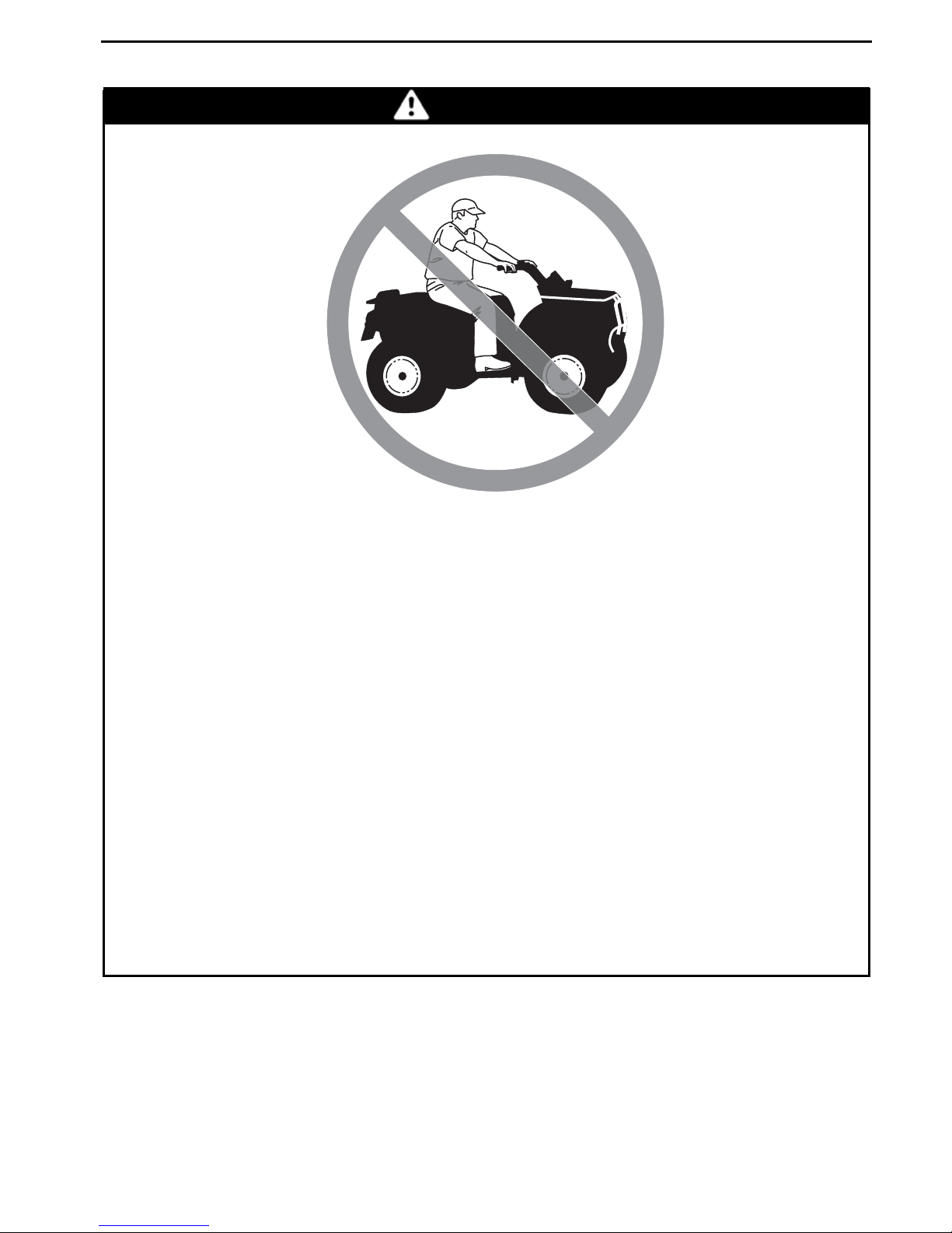
– Never carry a passenger on this vehicle.
– Never operate this vehicle on any paved surfaces, including sidewalks, drive-
ways, parking lots and streets.
– Never operate this vehicle on any public street, road or highway, even a dirt or
gravel one.
– Never take place on this vehicle without wearing an approved helmet that fits
properly. You should also wear eye protection (goggles or face shield), gloves,
boots, long sleeved shirt or jacket, and long pants.
– Never ride this vehicle under the influence of alcohol or drugs. They slow reac-
tion time and impair judgement.
– Never operate at excessive speeds. Always go at a speed that is proper for the
terrain, visibility, and operating conditions, and your experience.
– Never attempt wheelies, jumps, or other stunts.
– Always inspect and confirm the safe operating condition of your vehicle prior to
ride. Always follow the inspection and maintenance procedures and schedules
described in this Operator's Guide.
– Always keep both hands on the handlebars and both feet on the footpegsof the
vehicle during operation.
– Usingfoot protectors instead of footpegs as a resting area duringoperation may
lead to foot protector breakage. Your foot or leg may come into contact with the
rear wheels, which could injure you or cause an accident. Never use foot pro-
tectors as a resting area.
– Always go slowly and be extra careful when operating on unfamiliar terrain. Al-
ways be alert to changing terrain conditions when operating this vehicle.
– Never operate on excessively rough, slippery or loose terrain until you have
learned and practiced the skills necessary to control this vehicle on such terrain.
Always be especially cautious on these kinds of terrain.
– Always follow proper procedures for turning as described further in this Opera-
tor's Guide. Practice turning at low speeds before attempting to turn at faster
speeds. Do not turn at excessive speed.
– Never operate this vehicle on hills too steep for the vehicle or for your abilities.
Practice on smaller hills before attempting larger hills.
before operation.
SAFETY
________
SAFETY IN
FORMATION
________
9
Page 12

SPECIAL SAFETY MESSAGES
– Always follow proper procedures for climbing hills as described further in
this Operator's Guide. Check the terrain carefully before you start up any hill.
Never climb hills with excessively slippery or loose surfaces. Shift your weigh
forward. Never open the throttle suddenly or make sudden gear changes.
Never go over the top of any hill at high speed.
– Always follow proper procedures for going down hills and for braking on hills as
described further in this Operator's Guide. Check the terrain carefully be
you start down any hill. Shift your weight backward. Never go down a hill at
high speed. Avoid going down a hill at an angle that would cause the vehicle to
lean sharply to one side. Go straight down the hill where possi
– Always follow proper procedures for crossing the side of a hi
further in this Operator's Guide. Avoid hills with excessively slippery or loose
surfaces. Shift your weight to the uphill side of the vehicle. Never attempt to
turn the vehicle around on any hill until you have mastere
described in this Operator's Guide on level ground. Avoid crossing the side of a
steep hill if possible.
– Always use proper procedures if you stall or roll backwards when climbing a hill.
To avoid stalling, use proper gear and mainta
a hill. If you stall or roll backwards, follow the special procedure for braking
described in this Operator's Guide. Dismount on the uphill side or to a side
if pointed straight uphill. Turn the vehic
procedure described further in this Operator's Guide.
– Always check for obstacles before operating in a new area. Never attempt to
operate over large obstacles, such as large rocks or fallen trees. Always follow
proper procedures when operating
Operator's Guide.
– Always be careful when skidding or sliding. Learn to safely control skidding or
sliding by practicing at low speeds and on level smooth terrain. On extremely
slippery surfaces, such as ice
the chance of skidding out of control.
– Never operate this vehicle in fast flowing water or in water deeper than that
specified in this Operator's Guide. Remember that wet brakes may have
reduced stopping abili
apply them several times to let friction dry out the pads.
– Always use the size and type of tires specified further in this Operator's Guide.
Always maintain proper tire pressure as described further in this Operator's
Guide.
– Never modify this ve
Only use BRP's approved accessories.
– Neverexceed the stated load limits for this vehicle including the operator and all
other added accessories.
– Never operate this vehicle without proper instruction. Take a training course.
All operators
should receive training from a certified instructor.
ty. Test your brakes after leaving water. If necessary,
hicle through improper installation or use of accessories.
, go slowly and be very cautious in order to reduce
over obstacles as described further in this
in a steady speed when climbing
le around and remount, following the
d the turning technique
ble.
ll as described
fore
t
10
_______
SAFETY
INFORMATION
________
Page 13

SPECIAL SAFETY MESSAGES
FOR MORE INFORMATION ABOUT ATV SAFETY, contact an authorized
Can-Am dealer to find out about available training courses nearest you.
USA and Canada only: call the Specialty Vehicle Institute of America (SVIA) at
1 800 887-2887 or in Canada, the Canada Safety Council (CSC) at 1 613 739-1535.
________
SAFETY IN
FORMATION
________
11
Page 14
OPERATION WARNINGS
The following warning and their format have been requested by the United States
Consumer Product Safety Commission and are required to be in the Operator's
Guide for all ATVs.
NOTE: The following illustrations are general representations only. Your model
may differ.
WARNING
V00A0AQ
POTENTIAL HAZARD
Operating this vehicle without proper instruction.
WHAT CAN HAPPEN
The risk of an accident is greatly increa
how to operate this vehicle properly in different situations and on different
types of terrain.
HOW TO AVOID THE HAZARD
Beginning and inexperienced operators should complete a training course.
They should then regularly practice the skills learned in the course and the
operating techniques described in this Operator's Guide.
For more information about the training course, contact an authorized
Can-Am dealer.
sed if the operator does not know
12
_______
SAFETY
INFORMATION
________
Page 15
V00A01Q
OPERATION WARNINGS
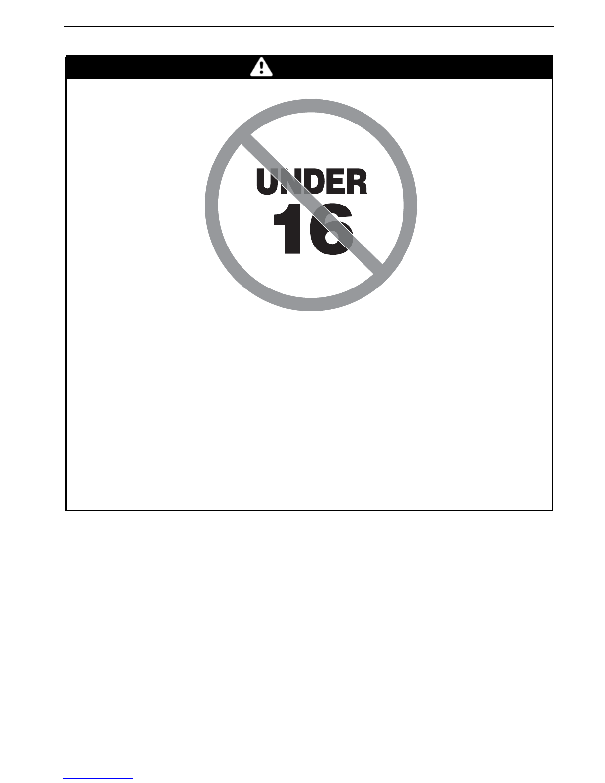
WARNING
POTENTIAL HAZARD
Failure to follow the age recommendations for this vehicle.
WHAT CAN HAPPEN
A lack of respect for this age recommendation can lead to severe injury or
death of the child.
Even though a child may be within the age group for which this vehicle is
recommended, he may not have the skills, abilities, or judgment needed to
operate this vehicle safely and may be involved in a serious accident.
HOW TO AVOID THE HAZARD
No one under 16 should operate this vehicl
e.
________
SAFETY IN
FORMATION
________
13
Page 16
OPERATION WARNINGS
V00A02Q
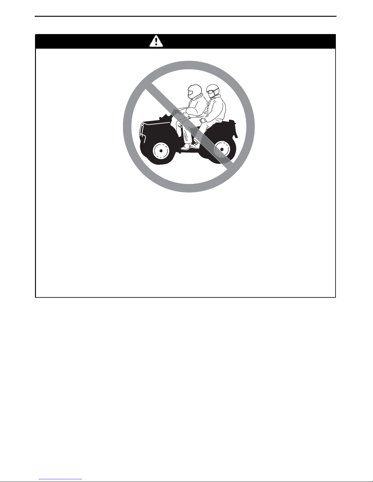
WARNING
POTENTIAL HAZARD
Carrying a passenger on this vehicle.
WHAT CAN HAPPEN
Greatly reduces your ability to balance and control this vehicle.
Could cause an accident, resulting in harm to you and/or your passenger.
HOW TO AVOID THE HAZARD
Never carry a passenger. Even with a long seat that provides unrestricted
operator movement, it is not designed nor intended to carry passenger(s).
14
_______
SAFETY
INFORMATION
________
Page 17
V00A03Q
OPERATION WARNINGS
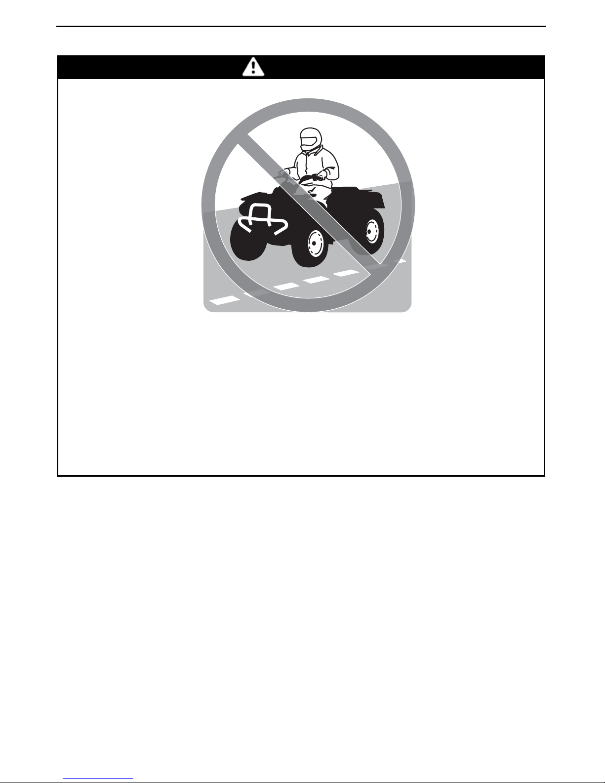
WARNING
POTENTIAL HAZARD
Operating this vehicle on paved surfaces.
WHAT CAN HAPPEN
The tiresare designed for off-road use only,not for use on pavement. Paved
surfaces may seriously affect handling and control of this vehicle, and may
cause the vehicle to go out of control.
HOW TO AVOID THE HAZARD
Never operate this vehicle on any paved s
driveways, parking lots and streets.
urfaces, including sidewalks,
________
SAFETY IN
FORMATION
________
15
Page 18
OPERATION WARNINGS
V00A04Q
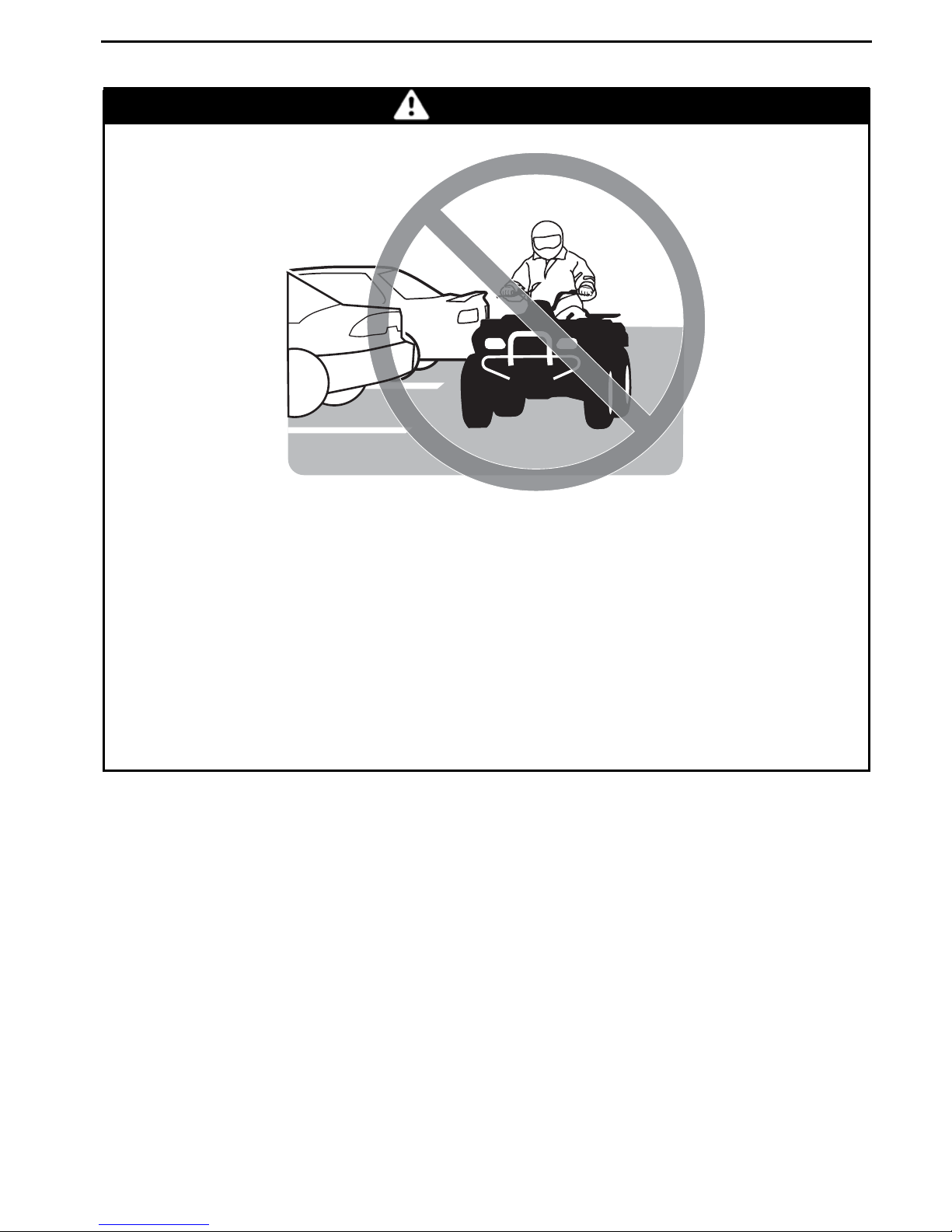
WARNING
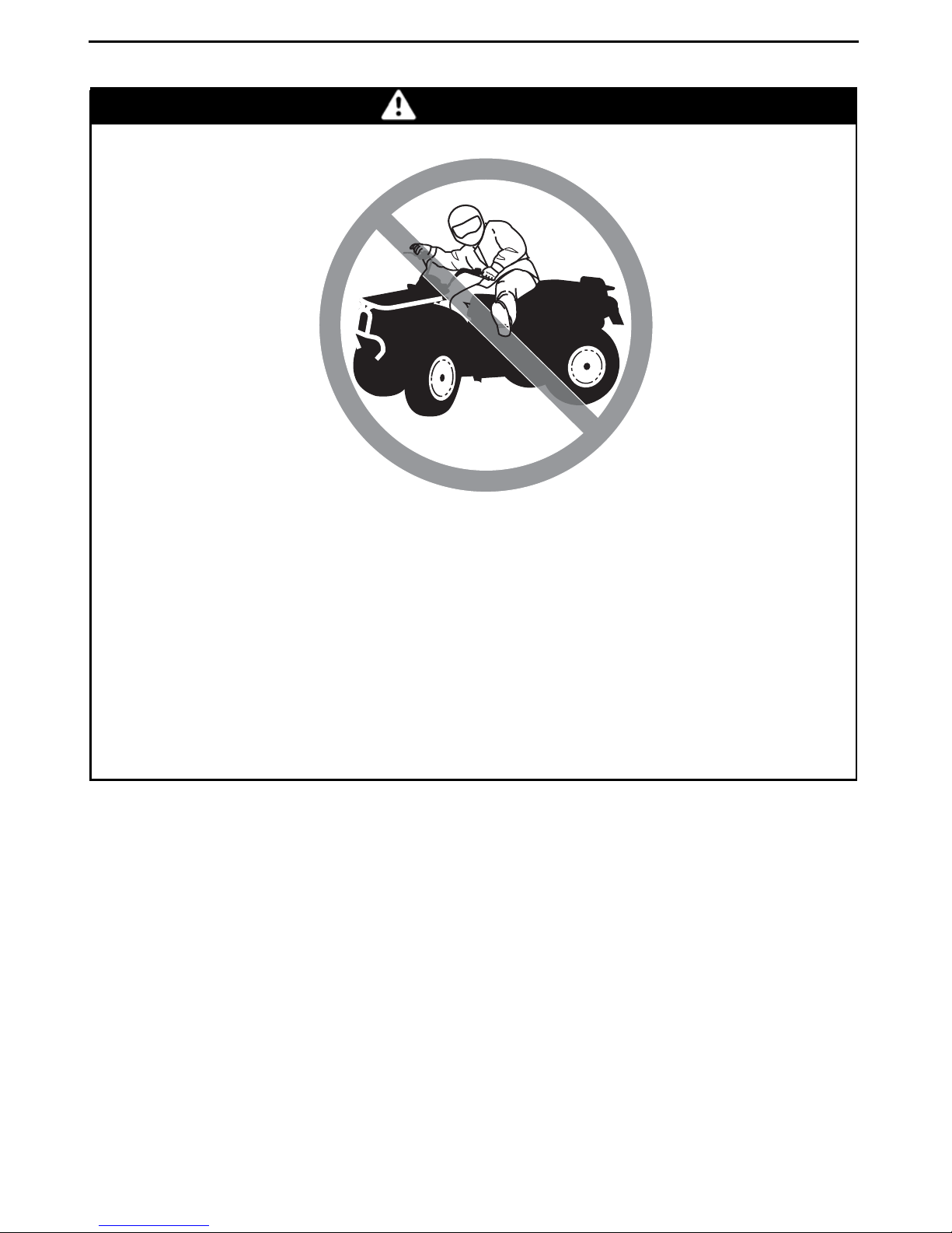
POTENTIAL HAZARD
Operating this vehicle on public streets, road
WHAT CAN HAPPEN
You can collide with another vehicle.
HOW TO AVOID THE HAZARD
Never operate this vehicle on any public street, road or highway, even a dirt
or gravel one. In many states or provinces it is illegal to operate this vehicle
on public streets, roads or highways.
sorhighways.
16
_______
SAFETY
INFORMATION
________
Page 19
V00A06Q
OPERATION WARNINGS
WARNING
POTENTIAL HAZARD
Ridingthis vehicle without wearing an approve
protective clothing.
d helmet, eye protection and
WHAT CAN HAPPEN
The following items concern all ATV's operator:
– Riding without an approved helmet increases the chances of a severe
head injury or death in the event of an accident.
– Riding without eye protection can result in an accident and increases the
chances of a severe injury in the event of an accident.
– Ridingwithout protective clothing increases the chances of severe injury
in the event of an accident.
HOW TO AVOID THE HAZARD
Always wear an approved helmet that fits properly. You should also wear:
– Eye protection (goggles or face shield)
– Gloves and boots
– Long sleeved shirt or jacket
–Longpants.
________
SAFETY IN
FORMATION
________
17
Page 20
OPERATION WARNINGS
V00A07Q
WARNING
POTENTIAL HAZARD
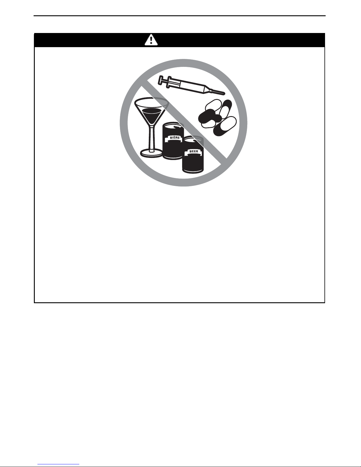
Riding this vehicle after consuming alcohol or drugs.
WHAT CAN HAPPEN
Could seriously affect your judgment.
Could cause you to react more slowly.
Could affect your balance and perception.
Could result in an accident or death.
HOW TO AVOID THE HAZARD
Never consume alcohol or drugs before or while riding this vehicle.
18
_______
SAFETY
INFORMATION
________
Page 21
V00A08Q
OPERATION WARNINGS
WARNING
POTENTIAL HAZARD
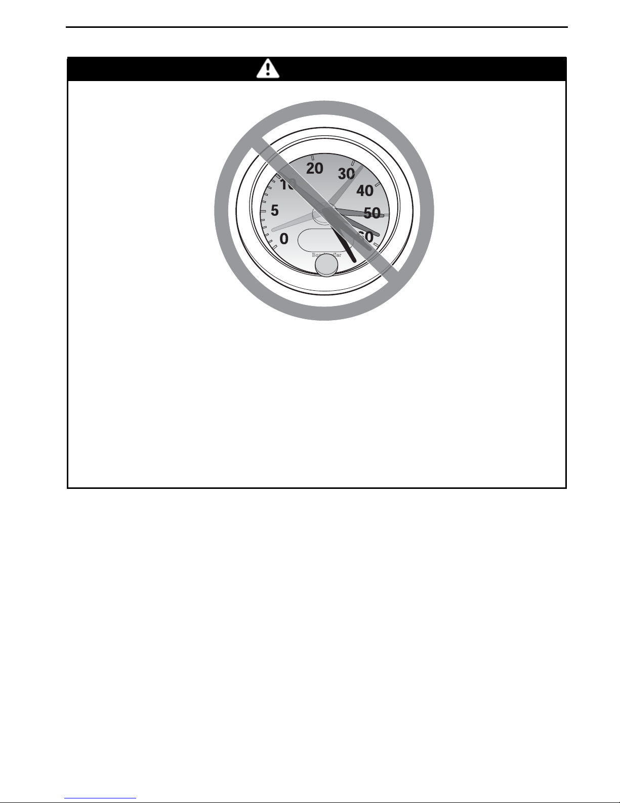
Operating this vehicle at excessive speeds.
WHAT CAN HAPPEN
Increases your chances of losing control of the vehicle, which can result in
an accident.
HOW TO AVOID THE HAZARD
Always travel at a speed which is proper for the terrain, visibility and operating conditions, and your experience.
________
SAFETY IN
FORMATION
________
19
Page 22
OPERATION WARNINGS
V00A09Q
WARNING
POTENTIAL HAZARD
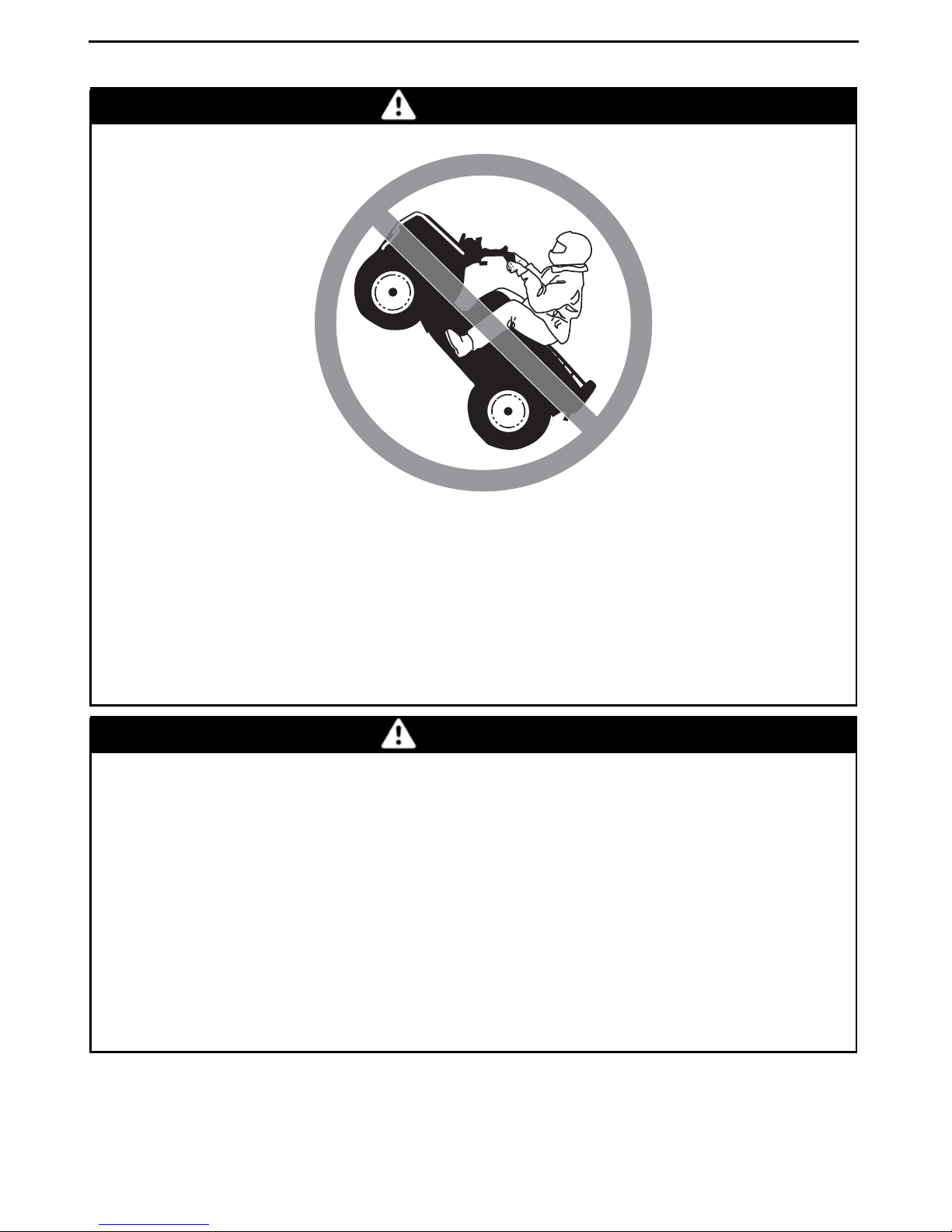
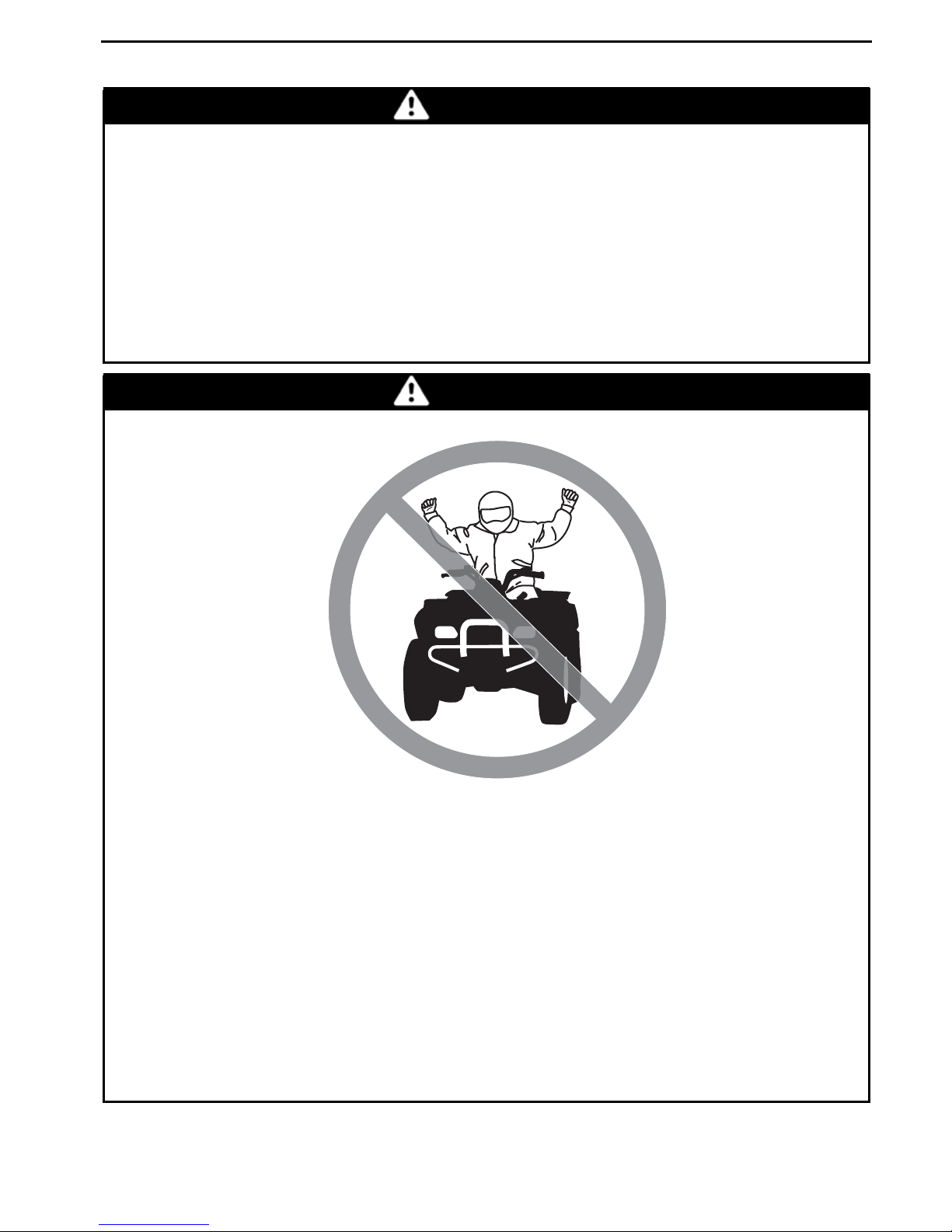
Attempting wheelies, jumps and other stunts.
WHAT CAN HAPPEN
Increases the chance of an accident, including an overturn.
HOW TO AVOID THE HAZARD
Never attempt stunts, such as wheelies or jumps. Do not try to show off.
WARNING
POTENTIAL HAZARD
Failure to inspect the vehicle before operating.
Failure to properly maintain the vehicle.
WHAT CAN HAPPEN
Increases the possibility of an accide
HOW TO AVOID THE HAZARD
Always inspect your vehicle every time prior to use it to make sure the vehicle is in safe operating condition.
nt or equipment damage.
Always follow the inspection and maintenance procedures and schedules
described further in this Operator's Guide.
20
_______
SAFETY
INFORMATION
________
Page 23
OPERATION WARNINGS
WARNING
POTENTIAL HAZARD
Riding on frozen waterways.
WHAT CAN HAPPEN
Breaking through the ice can lead to severe injury or death.
HOW TO AVOID THE HAZARD
Never ride this vehicle on a frozen surfacebefore you are sure the ice is thick
enough and sound enough to support the vehicle and its load, as well as the
force that is created by a moving vehicle.
WARNING
V00A0BQ
POTENTIAL HAZARD
Removing hands from handlebar or feet from the footrests during operation.
WHAT CAN HAPPEN
Removing even one hand or foot can reduce your ability to control the vehicle or could cause you to lose your balance and fall off the vehicle. If you remove a foot from thefootrests, your foot or leg may come into contact with
the rear wheels, which could injure you or cause an accident.
HOW TO AVOID THE HAZARD
Always keep both hands on the handlebar and both feet on the footrests
during vehicle operation.
________
SAFETY IN
FORMATION
________
21
Page 24
OPERATION WARNINGS
V00A0CQ
WARNING
POTENTIAL HAZARD
Failure to use extra care when operating this ve
WHAT CAN HAPPEN
You can come upon hidden rocks, bumps, or holes, without enough time to
react.
Could result in the vehicle overturning or loss of control.
HOW TO AVOID THE HAZARD
Go slowly and be extra careful when operating on unfamiliar terrain.
Always be alert to changing terrain condit
ions when operating the vehicle.
hicle on unfamiliar terrain.
22
_______
SAFETY
INFORMATION
________
Page 25

V00A0DQ
OPERATION WARNINGS
WARNING
POTENTIAL HAZARD
Failure to use extra care when operating on excessively rough, slippery or
loose terrain.
WHAT CAN HAPPEN
Could cause loss of traction or vehicle control, which could result in an accident, including an overturn.
HOW TO AVOID THE HAZARD
Do not operate on excessively rough, slippery or loose terrain until you
have learned and practiced the skills necessary to control this vehicle on
such terrain.
Always be especially cautious on these kinds of terrain.
________
SAFETY IN
FORMATION
________
23
Page 26
OPERATION WARNINGS
V00A0EQ
WARNING
POTENTIAL HAZARD
Turning improperly.
WHAT CAN HAPPEN
Vehicle could go out of control, causing a collision or overturn.
HOW TO AVOID THE HAZARD
Always follow proper procedures for turning as described further in this Operator's Guide. Practice turning at low speeds before attempting to turn at
faster speeds.
Do not turn at excessive speed.
24
_______
SAFETY
INFORMATION
________
Page 27

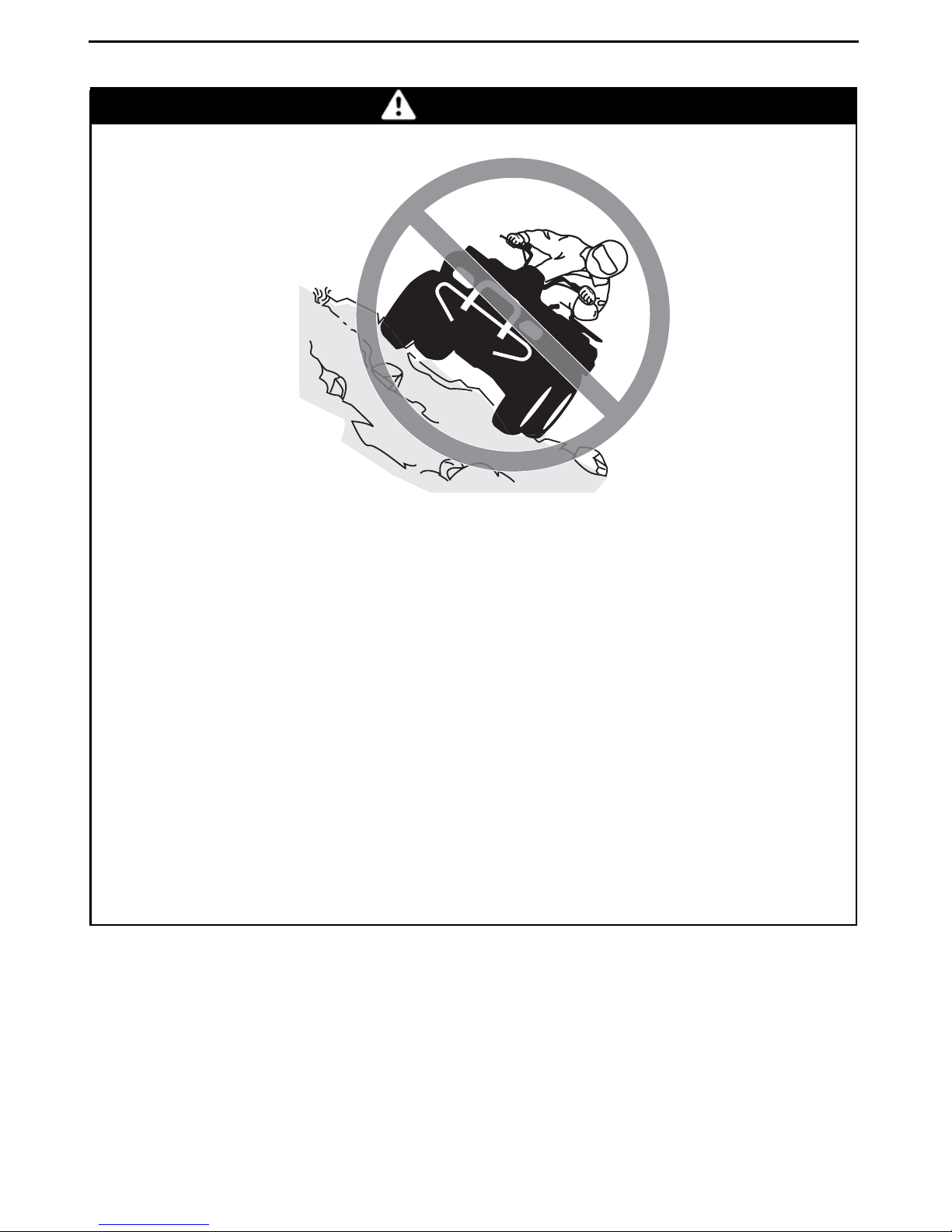
WARNING
OPERATION WARNINGS
V00AQQ
POTENTIAL HAZARD
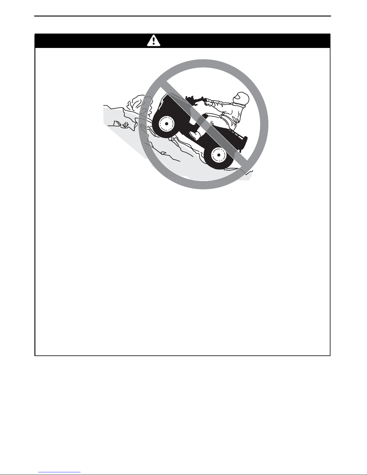
Operating on excessively steep hills.
WHAT CAN HAPPEN
The vehicle can overturn more easily on extremely steep hills than on level
surfaces or small hills.
HOW TO AVOID THE HAZARD
Never operate this vehicle on hills too steep for the vehicle or for your abilities.
Practice on smaller hills before attempting larger hills.
________
SAFETY IN
FORMATION
________
25
Page 28
OPERATION WARNINGS
V00A0FQ
WARNING
POTENTIAL HAZARD
Climbing hills improperly.
WHAT CAN HAPPEN
Could cause loss of control or cause vehicle to overturn.
HOW TO AVOID THE HAZARD
Always follow proper procedures for climbing hills as described further in
this Operator's Guide.
Always check the terrain carefully before you start up any hill.
Never climb hills with excessively slippery or loose surfaces.
Shift your weight forward.
Never open the throttle suddenly or make sudden gear changes. The vehi-
cle could flip over backwards.
Never go over the top of any hill at high speed. Anobstacle, a sharp drop, or
another vehicle or person could be on the other side of the hill.
26
_______
SAFETY
INFORMATION
________
Page 29

V00A0GQ
OPERATION WARNINGS
WARNING
POTENTIAL HAZARD
Going down a hill improperly.
WHAT CAN HAPPEN
Could cause loss of control or cause vehicle to overturn.
HOW TO AVOID THE HAZARD
Always follow proper procedures for going down hills as described further
in this Operator's Guide.
NOTE: A special technique is required when braking as you go down a hill.
Always check the terrain carefully before you start down any hill.
Shift your weight backward.
Never go down a hill at high speed.
Avoid going down a hill at an angle which would cause the vehicle to lean
sharply to one side. Go straight down the hill where possible.
________
SAFETY IN
FORMATION
________
27
Page 30
OPERATION WARNINGS
V00A0HQ
WARNING
POTENTIAL HAZARD
Improperly crossing hills or turning on hills.
WHAT CAN HAPPEN
Could cause loss of control or cause vehicle to overturn.
HOW TO AVOID THE HAZARD
Neverattempt to turn the vehicle around on anyhill until you have mastered
the turning technique as described further in this Operator's Guide on level
ground. Be very careful when turning on any hill.
Avoid crossing the side of a steep hill if possible.
When crossing the side of a hill:
Always follow proper procedures as described further in this Operator's
Guide.
Avoid hills with excessively slippery or loose surfaces.
Shift your weight to the uphill side of the vehicle.
28
_______
SAFETY
INFORMATION
________
Page 31

OPERATION WARNINGS
WARNING
V00A0IQ
POTENTIAL HAZARD
Stalling,rolling backwards or improperly dismounting while climbing a hill.
WHAT CAN HAPPEN
Could result in vehicle overturning.
HOW TO AVOID THE HAZARD
Use proper gear and maintain steady speed when climbing a hill.
If you lose all forward speed:
Keep your weight uphill. Never open the throttle suddenly or make sudden
gear changes. The vehicle could flip over backwards.
Apply the brakes.
Lock parking brake after you have stopped.
Dismount on uphill side, or to a side if pointed straight uphill.
If you begin rolling backwards:
Keep your weight uphill. Never open the throttle suddenly or make sudden
gear changes. The vehicle could flip over backwards.
Never apply the rear brake while rolling backwards.
Apply the front brake gradually.
When fully stopped, apply rear brake as well and lock parking brake.
Dismount on uphill side, or to a side if pointed straight uphill.
Turn the vehicle around and remount, following the procedure described
further in this Operator's Guide.
________
SAFETY IN
FORMATION
________
29
Page 32

OPERATION WARNINGS
V00A0JQ
WARNING
POTENTIAL HAZARD
Improperly operating over obstacles.
WHAT CAN HAPPEN
Could cause loss of control or a collision.
Could cause the vehicle to overturn.
HOW TO AVOID THE HAZARD
Before operating in a new area, check for obstacles.
Never attempt to ride over large obstacles, such as large rocks or fallen
trees.
When you go over obstacles, always follow proper procedures as described
further in this Operator's Guide.
30
_______
SAFETY
INFORMATION
________
Page 33

V00A0KQ
OPERATION WARNINGS
WARNING
POTENTIAL HAZARD
Skidding or sliding improperly.
WHAT CAN HAPPEN
You may lose control of this vehicle.
You may also regain traction unexpectedly, which may cause the vehicle to
overturn.
HOW TO AVOID THE HAZARD
Learn to safely control skidding or sliding by practicing at low speeds and
on level smooth terrain.
On extremely slippery surfaces, such as ice, go slowly and be very cautious
in order to reduce the chance of skidding or sliding out of control.
________
SAFETY IN
FORMATION
________
31
Page 34

OPERATION WARNINGS
V00A0LQ
WARNING
POTENTIAL HAZARD
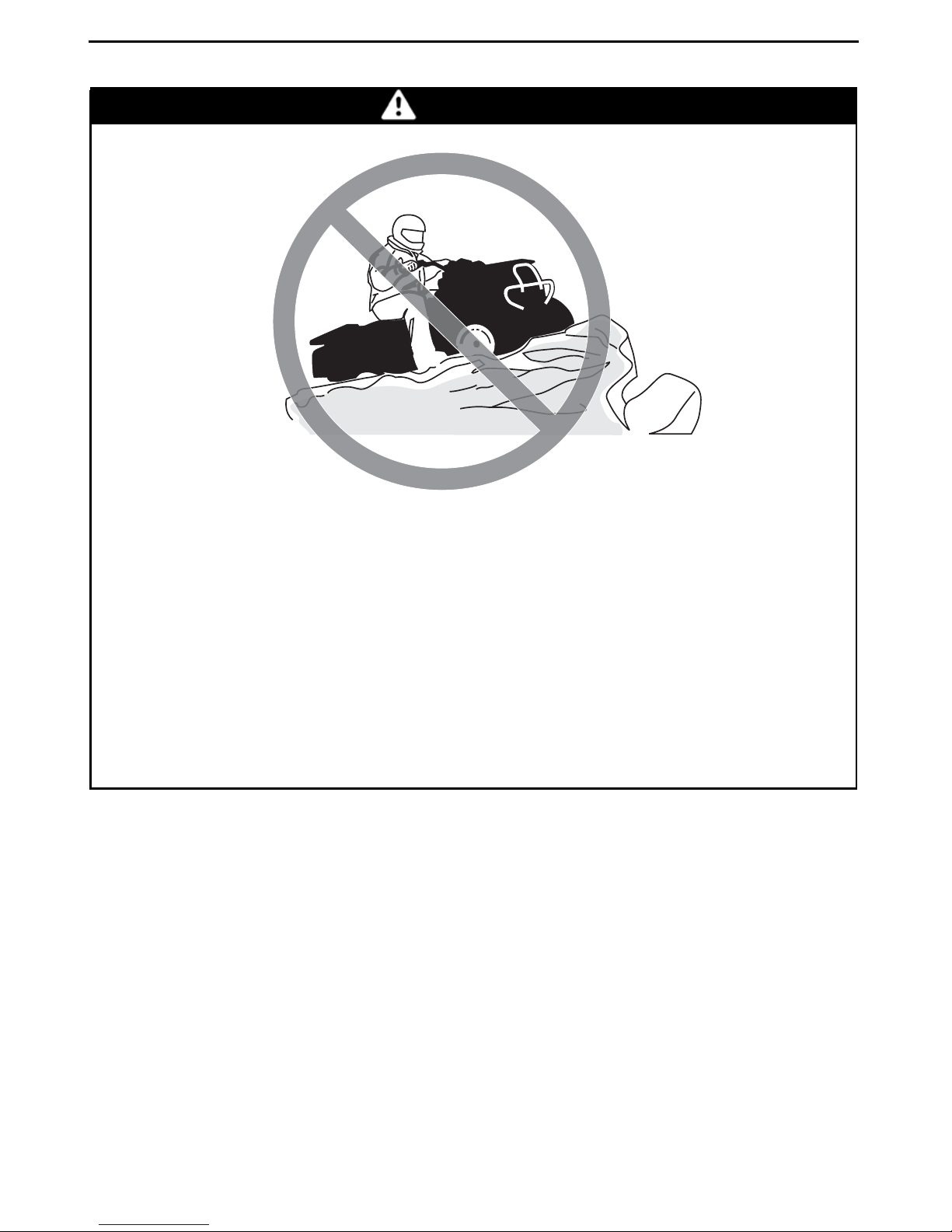
Operating this vehicle through deep or fast flo
wing water.
WHAT CAN HAPPEN
Tiresmay float, causing loss oftraction and loss of control,which could lead
to an accident.
HOW TO AVOID THE HAZARD
Never operate this vehicle in fast flowing water or in water deeper than that
specified further in this Operator's Guide.
Check water depth and current before you attempt to cross any water. Water should not go above footrests.
Remember that wet brakes may have reduced stopping ability. Test your
brakes after leaving water. If necessary, apply them several times to let
friction dry out the pads.
32
_______
SAFETY
INFORMATION
________
Page 35

V00A0OQ
OPERATION WARNINGS
WARNING
POTENTIAL HAZARD
Operating this vehicle with improper tires, or
pressure.
with improper or uneven tire
WHAT CAN HAPPEN
Use of improper tires on this vehicle, or operation of this vehicle with
improper or uneven tire pressure, may cause loss of control, tire blow outs,
tire to move around on its rim, and increases the risk of an accident.
HOW TO AVOID THE HAZARD
Always use the size and type of tires specified further in this Operator's
Guide for this vehicle.
Always maintain proper tire pressure as described further in this Operator's
Guide.
Always replace wheels or tires that are damaged.
________
SAFETY IN
FORMATION
________
33
Page 36

OPERATION WARNINGS
V00A0NQ
WARNING
POTENTIAL HAZARD
Operating this vehicle with improper modifica
tions.
WHAT CAN HAPPEN
Improper installation of accessories or modification of this vehicle may
cause changes in handling which in some situations could lead to an accident.
HOW TO AVOID THE HAZARD
Never modify this vehicle through improper installation or use of accessories. All parts and accessories added to this vehicle should be approved
by BRP and should be installed and used according to instructions. If you
have questions, consult an authorized Can-Am dealer.
Modification of the vehicle to increase speed and performance may violate
the termsand conditions of your vehicle's limited warranty. In addition, certain modifications including the removal of engine or exhaust components
are illegal under most laws.
34
_______
SAFETY
INFORMATION
________
Page 37

V02A02Q
OPERATION WARNINGS
WARNING
POTENTIAL HAZARD
Overloading this vehicle or carrying or towing
WHAT CAN HAPPEN
Could cause changes in vehicle handling which could lead to an accident.
HOW TO AVOID THE HAZARD
Never exceed the stated load capacity for this vehicle including operator as
well as other loads and added accessories.
Cargo should be properly distributed and securely attached.
Reduce speed when carrying cargo. Allow gr
Always follow the instructions in this Operator's Guide for carrying cargo.
cargo improperly.
eater distance for braking.
________
SAFETY IN
FORMATION
________
35
Page 38

OPERATION WARNINGS
V03M01Q
POTENTIAL HAZARD
WARNING
Transporting flammable or dangerous material can lead to explosions.
WHAT CAN HAPPEN
This can cause serious injury or death.
HOW TO AVOID THE HAZARD
Never transport flammable or dangerous material.
36
_______
SAFETY
INFORMATION
________
Page 39

RIDING THE VEHICLE
To fully appreciate the pleasures and excitement of riding this vehicle, there are
some basic rules and tips that you MUST follow. Some may be new to you while
others may be common sense or obvious.
Please take the time to study this Operator's Guide and all on-product safety labels
as well as the
scribe what you should know about this vehicle before riding it.
Whether you are a new user or an experienced rider, it is important for your
personal safety that you know the controls and features of this vehicle. Equally
important is knowing how to properly ride.
Information in this Operator's Guide is limited. It is strongly recommended that
you obtain further information and training from your local authorities, ATV clubs
or a recognized ATV training organization or contact an authorized Can-Am dealer.
USA and Canada only: to find out about available training course nearest you,
call the Specialty Vehicle Institute of America (SVIA) at 1 800 887-2887 or in
Canada, the Canada Safety Council (CSC) at 1 613 739-1535 ext. 227.
The U.S. Consumer Product Safety Commission and all ATV manufacturers do not
recommended anyone under the age of 16 to ride an ATV having an engine higher
than 90 cc. For the child's safety, we strongly recommend you also follow and enforce this recommendation. You are the sole judge of a rider's capability to understand the risks and operate a vehicle safely.
SAFETY DVD
that came with this vehicle. They more completely de-
Persons with cognitive or physical impairments or who are high risk takers have an
increased exposure to overturns or collisions which may result in injury including
death.
Not all vehicles are the same. Each has its own unique performance characteristics, controls and features. Each will ride and handle differently.
Become completely familiar with the operational controls and the general operation of the vehicle before venturing into off road conditions. Practice driving in a
suitable area free of hazards and feel the response of each control. Drive at low
speeds. Higher speeds require greater experience, knowledge and suitable riding
conditions.
Riding conditions vary from place to place. Each is subject to weather conditions
which may radically change from time to time and from season to season.
Riding on sand is different than riding on snow or through forests or marshes.
Each location may require a greater degree of awareness and skills. Show good
judgement. Always proceed with caution. Please do not take any unnecessary
risks that could leave you stranded or possibly injured.
While reading this Operator’s Guide, reminder that:
Indicates a potential hazard that, if not avoided, could result in serious
injury or death.
________
WARNING
SAFETY IN
FORMATION
________
37
Page 40

RIDING THE VEHICLE
Never assume that the vehicle will go everywhere safely. Sudden changes in terrain caused by holes, depressions, banks, softer or harder “ground” or other irregularities may cause the vehicle to topple or become unstable. To avoid this, slow
down and always observe the terrain ahead. If the vehicle does begin to topple or
tip over, the best advice is to immediately get off... AWAY from the direction of the
tip over!
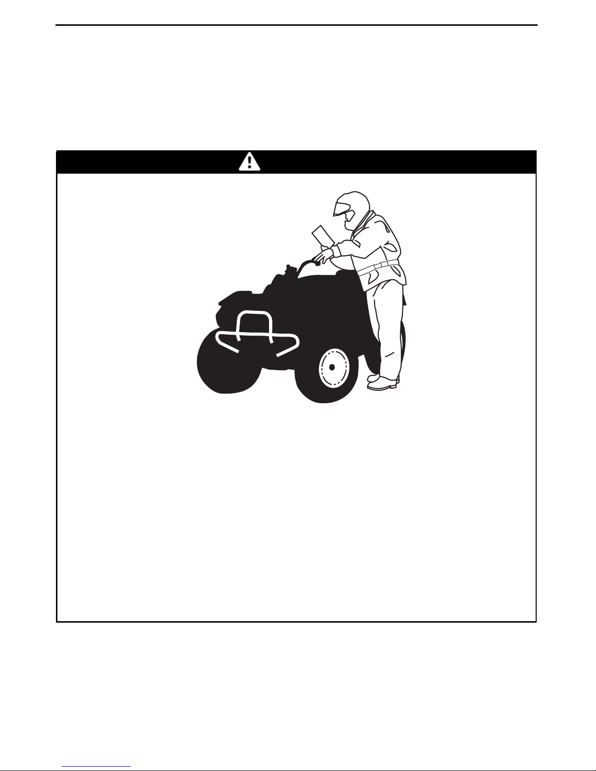
Pre-Ride Inspection
WARNING
Perform a pre-ride inspection before each ride to detect potential problems
during operation. The pre-ride inspection can help you monitor wear and
deterioration before they become a problem. Correct any problems that
you discover to reduce the risk of a breakdown or crash. See an authorized
Can-Am dealer if necessary.
Before using this vehicle, the operator should always:
– Apply parking brake and check if it operates properly.
– Check tire pressure and condition.
– Check wheels and bearings for wear and damage.
– Check location of controls and ensure they work properly.
– Verify if steering operates freely.
– Activate throttle control lever several times to ensure it operates freely. It must
return to idle position when released.
– Activate the brake lever and brake pedal to make sure the brakes fully apply.
They must fully return when released.
– Ensure front brake lever position is adjusted to suit drivers hand.
– Check all brake line fittings for tightness and against leaks.
– With parking brake correctly applied, activate the clutch lever. It must fully re-
turn when released.
– Check drive chain for adjustment and lubrication.
– Check sprockets for wear and damages.
– Check tightening of rear axle fasteners.
– Check swing arm, if any lateral play is detected DO NOT USE THE VEHICLE.
– Check fuel, oil and coolant levels.
– Check for oil leaks on the engine, oil tank and transmission.
– Check radiator cleanliness.
– Clean headlights and taillight.
– Ensure seat is properly latched.
– If you transport cargo, respect load capacity. Ensure cargo is properly secured
to the vehicle.
– Look and feel for loose parts while engine is off. Check fasteners.
38
_______
SAFETY
INFORMATION
________
Page 41

RIDING THE VEHICLE
– Ensure the path of travel is free of persons and obstacles.
– Check operation of ignition switch, engine start button, engine stop switch,
headlights, taillight and indicator lights.
– Start engine, remove parking brake and drive forward slowly a few feet then ap-
ply all brakes individually to test them.
Correct any problem you may have found before riding. See an authorized
Can-Am dealer if necessary.
Clothing
Actual weather conditions should help you decide how to dress. Howev
is important that the operator always wears the appropriate protective clothing
and apparel, including an approved helmet, eye protection, boots, gloves, a long
sleeved shirt and pants. This type of clothing will provide you pr
some of the minor hazards you may encounter en route. The operator must
never wear loose clothing such as a scarf that may get entangled in the vehicle or
on tree branches and shrubs. Depending on conditions
sunglasses may be required. Different colored lenses available for goggles or sun
glasses help you distinguish terrain variations. Sunglasses should only be worn
during the daytime.
, antifogging goggles or
otection from
er, it
________
SAFETY IN
FORMATION
________
39
Page 42

RIDING THE VEHICLE
Approved
helmet
Eye protection
Rigid chin
guard
Chest
protector
Long
sleeves
Gloves
Long, sturdy
pants
Boots
V00A0RN
Carrying Passenger
This vehicle is designed specifically to carry an operator only. This vehicle is not
designed nor intended to carry passenger(s). Carrying passenger(s) may affect
the stability and your control of the vehicle.
Carrying Loads
Never load cargo on this vehicle.
Recreational Riding
Respect the rights and limitations of others. Stay away from areas designated
for other types of off road use. This includes snowmobile trails, equestrian trails,
cross country ski trails, mountain bike trails etc. Never assume there are no other
40
_______
SAFETY
INFORMATION
________
Page 43

RIDING THE VEHICLE
usersonthetrail. Alwaysstaytothecompleterightofthetrailanddonotzigzag
toonesideofthetrailthentheother. Bepreparedtostoporpullofftothesideif
another trail user appears in front of you.
Join a local ATVclub. Itwill provide you with a map and advice or inform you where
you can ride. Ifa club does not exist in your area, help to startone. Groupridinga
club activities provide a pleasurable, social experience.
Always keep a safe distance from other riders. Your judgment of speed, terrain conditions, weather, mechanical condition of your vehicle and the “trust in
judgment” you have in others around you will help you make a better choice of
appropriate safe distance. This vehicle, like any other motorize
stop “on a dime”.
d vehicle, cannot
nd
Before you ride, tell someone where you are planning to travel and y
time of return. Never consume alcohol or drugs before or while riding!
Depending on the length of your ride, carry additional tools or eme
ment. Find out where you can get additional gasoline and oil. Be prepared for the
possible conditions you may encounter. An emergency first aid kit should always
be a consideration.
our expected
rgency equip-
Environment
One of the benefits of this vehicle is that it can take you
from most communities. However, you should always respect nature and the
rights of others to enjoy it. Do not ride in environmentally sensitive areas. Do not
drive over forest crops or shrubs... nor cut dow
spin your wheels and destroy the terrain. “Tread Lightly”.
Chasing wildlife is in many areas illegal. Wild
chased by a motorized vehicle. If you encounter animals on the trail, stop and observe quietly and with caution. It will be one of the better memories of your life.
Observe the rule... “what you take in, carry out”. Do not litter. Do not start campfires unless you have permission to do so... and then only... away from dry areas.
The hazards you may create on thetrail ma
at a later date.
y cause injury to others or yourself, even
n trees or take down fencing... nor
life can die of exhaustion after being
off the beaten path away
Respect farm lands. Always obtain the pe
on private land. Respect crops, farm animals and property lines. If you come to a
closed a gate, close it again behind you.
Finally, do not pollute streams, lakes or rivers and do not modify the engine or muffling system, or remove any of its components.
Design Limitation
Although the vehicle is exceptionally rugged for its class, it is still a light vehicle by
definition and its operation must b
The addition of weight to any part of the vehicle changes its gravitational stability
and modifies its performance.
________
e restricted to its proper purpose.
SAFETY IN
rmission of the landowner before riding
FORMATION
________
41
Page 44

RIDING THE VEHICLE
Off-Highway Operation
The very nature of off-highway operation is dangerous. Any terrain, which has
not been specially prepared to carry vehicles, presents an inherent danger where
angularity, terrain substance and exact steepness are unpredictable. The terrain
itself presents a continual element of danger, which must be knowingly accepted
by anyone venturing over it.
An operatorwho takesa vehicle off-road should always exercise the utmost care i
selecting the safest path and keeping close watch on the terrain ahead of him. On
no account should the vehicle be operated by anyone who is not completely familiar with the driving instructions applicable to the vehicle, nor s
on steep or treacherous terrain.
hould it be operated
General Operating and Safety Precautions
Care, caution, experience and driving skill are the bestprecautions against the hazards of vehicle operation.
Whenever there is the slightest doubt that the vehicle can safely negotiate an obstacle or a particular piece of terrain, always choose an alternate route.
In off-road operation, power and traction, not speed, are important. Never drive
faster than visibility and your own ability to select a safe route permit.
Constantly watch the terrain ahead for sudden changes in slopes or obstacles,
such as rocks or stumps, that may cause loss of stability, resulting in tip over or
rollover.
Never operate the vehicle if the controls do not function normally.
When stopped or parked, always apply the parking brake. This is especially impor-
tant when parking on a slope. On very steep inclines or if the vehicle is carrying
cargo, the wheels should be blocked using rocks or
fuel valve to the closed position.
bricks. Remember to turn the
n
Uphill Driving
Due to configuration, this vehicle has excellent climbing ability, so much so that
tip over is possible before traction is lost.
terrain situations where the top of the hill has eroded to a point that the hill peak
rises very sharply. The vehicle can readily negotiate such a condition, however,
in doing so, when the front of the vehicle is
balance changes rearward tip over can occur.
The same situation may apply if an embedded
cle to climb more than desired. If such a situation occurs take an alternate route.
Be aware of side hilling dangers when doing so.
It is also wise to know the terrain condition on the other side of the hill or bank. All
too often there exists a sharp drop-off that is impossible to negotiate or descend.
42
_______
SAFETY
For example, its common to encounter
driven to a point that the vehicle's
object causes the front of the vehi-
INFORMATION
________
Page 45

RIDING THE VEHICLE
Downhill Driving
This vehicle can climb steeperslopes that it can descend safely. Therefore, it is essentialtoassurethatasaferouteexiststodescendaslopebeforeyouclimbit.
Decelerating while negotiating a slippery downhill slope could “toboggan” the vehicle. Maintain steady speed and/or accelerate slightly to regain control.
Side Hilling
Whenever possible, such operation should be avoided. If necessary, do so with
extreme caution. Side hilling on steep inclines could result in rollove
slippery or unfirm surfaces could result in uncontrollable side sliding. Do not attempt to turn the vehicle downhill with the slide. Avoid all objects or depressions
that will intensify the raising of one side of the vehicle higher than
causing rollover.
Drop-Offs
This vehicle will “bottom-out” and usually stop if eitherthe frontor rear wheels are
driven over a drop-off. If the drop is sharp or deep, the vehi
over.
cle will nose dive and tip
r. In addition,
the other, thus
WARNING
Avoid negotiating drop-offs. Reverse and select an alternate route.
Riding on Snow Covered Surfaces
When performing the pre-ride inspection, pay special attention to locations on the
vehicle where snow and/or ice accumulations may obstruct visibility of the tail
lamp, clog ventilation openings, block the radiator and fan, and interfere with the
movement of control levers, switches and brake pedal. Before starting with your
ATV check the steering, throttle and brake lever and pedal controls for interference
free operation.
Whenever an ATV is ridden on a snow covered drive path the tire grip is generally
reduced causing the vehicle to react differently to control inputsfrom the operator.
On low grip surfaces, the steering responses are not as crisp and precise, stopping
distances are lengthened and acceleration becomes sluggish. Slow down and do
not "gun" the throttle. This will only result in spinning of the tires and possibly in an
over steering slide of the vehicle. Avoid hard braking. This will possibly result in a
straight line slide of the vehicle. Again, the best advice is to safely reduce speed in
anticipation of a maneuver so to give yourself time and distance to regain total vehicle control before it spins out of your control.
As you drive your ATV over a loose snow covered surface, snow dust will be
picked up in the wake turbulence of the moving vehicle and transported to contact
and accumulate or melt on some exposed components including rotating parts
like brake discs. Water, snow or ice may affect the response time of the brake
system of your ATV. Even when not required to reduce vehicle speed apply brakes
frequently to prevent ice or snow accumulation and to dry brake pads and discs.
________
SAFETY IN
FORMATION
________
43
Page 46

RIDING THE VEHICLE
While doing so in low risk driving situations you will test for grip level and keep
yourself alerted to how the vehicle reacts to your control inputs. Always keep
brake pedal, footrests, floor boards, brake and throttle levers free of snow and
Frequently wipe snow off seat, handgrips, head and tail lamps.
The depth of the snow cover may hide rocks, tree stumps or other objects and if it
is wet may totally impede the drivability as the vehicle becomes bogged down or
completely looses traction in slushy snow. Look far ahead and always be watchful
of any visible clues that might indicate the presence of such obstacles. In do
steer clear. Avoid driving on any frozen body of water before checking that the
ice will safely support the ATV, its riders and its load of cargo. Remember that a
given thickness of ice may be sufficient to support a snowmobil
of an identical weight because of the smaller load bearing surface of the four tire
contact patches as compared to that of a snowmobile track and skis.
Always remember that the vehicle handling and stability is affected when riding
with a passenger. So never attempt maneuvers with a passenger that may cause
the vehicle to enter into a slide that if halted abruptly wil
the passenger and/or a vehicle roll or tipover.
l result in the ejection of
e but not an ATV
ice.
ubt
To maximize comfort and avoid frostbite, always wea
equipment appropriate for the weather conditions you will be exposed to during
your ride.
At the end of each rideit isa good practice to clean the vehicle body and all moving
components (brakes, steering components, drivelines, controls, radiator fan etc.)
from any snow or ice accumulations. Wet snow will
down period and become more difficult to remove at the next pre-ride inspection.
r clothing andATV protective
turn to ice during the shut
Riding Techniques
Riding your vehicle too fast for the conditions may result in injury. Apply only
enough throttle to proceed safely. Statistics show that high speed turns usually
result in mishaps and injury. Always remem
weight alone may entrap you should it fall and pin you down.
This vehicleis not designed for jumpi
impacts such as jumping. Performing “wheelies” can cause the vehicleto flip over
onto you. Both practices have a highrisk for youand shouldbe avoidedat alltimes.
To maintain proper control it is strongly advised that you keep your hands on the
handlebar and within easy reach of all controls. The same holds true for your feet.
To minimize the possibility of any l
at all times. Do not direct your toes outwards nor place your foot out to assist
turning as they can be hit or snagged by passing obstacles or may contact the
wheels.
ng nor can it, or you, absorb the energy of high
eg or foot injury, keep your feet on the footrests
ber that this vehicle is heavy! Its pure
44
_______
SAFETY
INFORMATION
________
Page 47

RIDING THE VEHICLE
V00A0UL
Even though there is an adequate suspension systems on this vehicle there are
“washboard” or rough terrain conditions that will make you feel uncomfortable
and even cause back injury. “Posting” or riding in a crouched position will often
be required. Slow down and allow your flexed legs to absorb impact.
This vehicle is not designed for riding on roads or highways. In most places it is an
illegal practice. Riding your vehicle on roads or highways could cause a collision to
occur with another vehicle.
The tires of this vehicle are not suitedfor paved road use. Pavement may seriously
affect the handling and control of the vehicle.
Riding on roads or soft shoulders may confuse other road users, especially if your
lights are on.
If you have to cross a road, the lead driver should get off his vehicle, then observe
and give directions to the other riders. The last person after crossing then assists
the lead driver to cross. Do not travel sidewalks. They are designated for pedestrian use.
Water can be a unique hazard. If it is too deep the vehicle may “float” and topple.
Check the water depth and current before you attempt to cross any water. Water
should not go above the footrest. Be wary of slippery surfaces such as rocks,
grass, logs, etc., both in the water and on its banks. A loss of traction may occur.
Do not attempt to enter the water at high speed. The water will act as a brake and
could throw you off the vehicle.
________
SAFETY IN
FORMATION
________
45
Page 48

RIDING THE VEHICLE
V00A0VL
Water will affect the braking ability of your vehicle. Make sure you dry the brakes
by applying them several times after the vehicle leaves the water.
Mud or marsh lands may be encountered near water. Be prepared for sudden
“holes” or changes in depth. Similarly so, be watchful of hazards such as rocks,
logs, etc., partially covered by vegetation.
If your trip crosses frozen waterways, make sure that the ice is thick enough and
sound enough to support the total weight of yourself, the vehicle and its load. Be
ever watchful of open water... it is a sure indication that the ice thickness will vary.
If in doubt, do not attempt to cross.
Ice will also affect the control of the vehicle. Slow down and do not “gun” the
throttle. This will only result in spinning of the tires and possible tip over of the
vehicle. Avoid rapid braking. This again will possibly result in an uncontrolled slide
and tip over of the vehicle. Slush should be avoided at all times since it could block
the operation or controls of the vehicle.
Riding in snow may affect the brakes stopping ability. Safely reduce speed and
allow greater distance for braking. Snow projection may cause ice build up or
snow accumulation on brake components and controls. Apply brakes frequently
to prevent ice or snow accumulation. Carefully inspect the brake system before
each ride and always keep brake pedal, footrests, floor boards and brake levers
free of snow and ice.
Sand and riding on sand dunes or on snow is another unique experience but
there are some basic precautions that should be observed. Wet, deep or fine
sand/snow may create a loss of traction and cause the vehicle to slide, drop off
or become “bogged” down. If this occurs look for a firmer base. Again, the best
advice is to slow down and be watchful of the conditions.
46
_______
SAFETY
INFORMATION
________
Page 49

RIDING THE VEHICLE
When riding in sand dunes it is advisable to equip the vehicle with an antenna type
safety flag. This will help make your location more visible to others over the next
sand dune. Proceed carefully should you see another safety flag ahead. Since the
antenna type safety flag can snag and rebound on your body if caught, do not use it
in areas where there are low hanging branches or obstacles.
Riding on loose stones or gravel is very similar to riding on ice. They will affect
the steering of vehicle... possibly causing it to slide and tip over especially at
high speeds. In addition, braking distance may be a affected. Remember that
“gunning” the throttle or sliding may cause loose stones to be ejected rearwards
into the path of another rider's way. Never do it deliberately.
V00A0WL
If you do get into a slide or skid, it may help to turn the handlebar into the direction
of the skid until you regain control. Never jam the brakes and lock the wheels.
Respect and follow all posted trail signs. They are there to help you and others.
Obstacles in the “trail” should be traversed with caution. This includes loose
rocks, fallen trees, slippery surfaces, fences, posts, and embankments and
depressions. You should avoid them whenever possible. Remember that some
obstacles are too large or dangerous to cross and should be avoided. Small rocks
or fallen trees may be safely crossed... approach at a 90° angle. Stand on the
footrests while keeping your knees flexed. Adjust speed without losing momentum and do not “gun” the throttle. Hold handlebar firmly. Place your body weight
rearwards and proceed. Do not try to lift the vehicle front wheels off the ground.
Be aware that the object may be slippery or may move while crossing.
When driving on hills or slopes two things are highly important... be prepared
for slippery surfaces or terrain variations and obstacles and... use proper body
positioning.
When stopped or parked always apply the parking device. This is especially important when parking on a slope. On very steep inclines or if the ATV is carring a cargo,
the wheels should be blocked using rocks or bricks.
________
SAFETY IN
FORMATION
________
47
Page 50

RIDING THE VEHICLE
Uphill
Keep your body weight forward towards the top of the hill. Keep your feet on the
footpegs and shift into low gear then accelerate and when necessary, change gear
quickly as you climb. Do not over-speed since this may cause the front of the vehicle to lift from the ground and fall back on you. If the hill is too steep and you cann
proceed or the vehicle begins to roll backwards, apply the brake, being careful not
toslide. Dismountthenusethe“U”turnor“K”turn(whilewalkingback,nextto
the vehicle on the up hill side and with a hand on the brake lever, slowly back th
rear of the vehicle toward the top of the hill then drive downhill). Always walk or
dismount on the upside of the slope while keeping clear of the vehicle and its rotating wheels. Do not try to hold on to the vehicle if it begins to
Do not ride over the crestof the hill at high speed. Obstacles,including sharp dropoffs, may exist.
topple. Stay clear.
ot
e
V00A0XL
Downhill
Keep your body weight rearwards. Apply the brake gradually to prevent skidding.
Do not “coast” down the slope using solelyengine compressionor in neutral gear.
48
_______
SAFETY
INFORMATION
________
Page 51

RIDING THE VEHICLE
V00A0YL
Side Hilling
This is one of the most risky types of riding since it may drastically change the balance of the vehicle. It should be avoided whereverpossible. Ifit is necessary to do
so however, it is important that you ALWAYS keep your body weight on the upside
of the slope... and be prepared to dismount on that side should the vehicle begin
to topple. Do not try to stop or save the vehicle from damage.
V00A0ZL
While reading this Operator’s Guide, reminder that:
Indicates a potential hazard that, if not avoided, could result in serious
injury or death.
________
WARNING
SAFETY IN
FORMATION
________
49
Page 52

IMPORTANT ON-PRODUCT LABELS
Hang Tag
This vehicle comes with a hang tag and labels containing important safety information.
Any person who rides this vehicle should read and understand this information before riding.
vmo2009-005-003_en
704901107
vmo2006-005-009_en
50
_______
SAFETY
Vehicle Safety Labels
The followinglabels are on your vehicle
and they should be considered permanent parts of the vehicle. If missing or
damaged, they can be replaced free
of charge. See an authorized Can-Am
dealer.
NOTE: The following illustrations used
in this Operator's Guide are a general
representation only. Your model may
differ.
INFORMATION
________
Page 53

IMPORTANT ON-PRODUCT LABELS
vmo2008-011-021_a
vmo2008-011-022_a
vmo2008-011-023_a
vmo2008-011-061_b
UNDERNEATH ACCESS COVER
vmo2008-011-098_b
________
SAFETY IN
vmo2008-011-025_a
FORMATION
________
51
Page 54

IMPORTANT ON-PRODUCT LABELS
NEVER USE UNDER
THE INFLUENCE OF
DRUGS OR ALCOHOL.
vmo2009-003-004_en
LABEL 1
vmo2010-004-002_en
LABEL 4
V01M02Z
LABEL 2
V02M05Y
LABEL 3
52
_______
SAFETY
V01M07Z
LABEL 5
Improper tire pressure or
overloading can cause
loss of control, resulting
in SEVERE INJURY or
DEATH.
ALWAYS maintain proper tire pressure as shown.
NEVER set tire pressure below minimum. It could cause the tire to
disloge from the rim.
NEVER exceed the vehicle load capacity of 100 kg (220 lb)
Including weight of operator and accessories.
704902001
LABEL 6
INFORMATION
LOAD
UP TO
100 kg
(220 lb)
COLD TIRE PRESSURE
FRONT
MAX: 68.9 kPa (10 PSI)
MIN: 55.2 kPa (8 PSI)
REAR
MAX: 62.1 kPa (9 PSI)
MIN: 48.3 kPa (7 PSI)
________
Page 55

IMPORTANT ON-PRODUCT LABELS
Compliance Labels
vmo2010-010-100_a
LABEL 7
vmo2008-011-090
LABEL 8
vmo2010-004-001_en
LOCATED ON LEFT SIDE MEMBER OF
FRAME
ACN 097 370 100
POWER
PUISSANCE
WET WEIGHT
POIDS EN ETAT
DE MARCHE
THIS VEHICLE IS AN ALL TERRAIN VEHICLE AND IS NOT INTENDED FOR USE ON PUBLIC ROADS.
CE VEHICULE EST UN VEHICULE TOUT TERRAIN QUI N'EST PAS DESTINÉ À ÊTRE UTILISÉ SUR
LES VOIES PUBLIQUES.
vmo2008-011-091
kW
kg
LOCATED ON RIGHT SIDE MEMBER OF
FRAME
704902057
LOCATEDONLEFTSIDEMEMBEROFFRAME
________
SAFETY IN
FORMATION
________
53
Page 56

IMPORTANT ON-PRODUCT LABELS
Technical Information
Label
vmo2008-011-024_b
TYPICAL
1. Drive chain label
DRIVE CHAIN
DRIVE CHAIN MUST BE WELL ADJUSTED AND
LUBRIC ATED. FREE PL AY IS xx mm (x/x") WITH
DRIVER ON VEHICLE. SEE OWNERS MANUAL
FOR COMPLETE INSTRUCTIONS.
vmo2008-011-088_en
xx mm (x/x")
While reading this Operator’s Guide, reminder that:
Indicates a potential hazard that, if not avoided, could result in serious
injury or death.
54
_______
WARNING
SAFETY
INFORMATION
________
Page 57

VEHICLE
INFORMATION
_______________
55
Page 58

CONTROLS/INSTRUMENT/EQUIPMENTS
7
6
3
5
9
4
2
1
8
10
vmo2009-005-002_c
TYPICAL
While reading this Operator’s Guide, reminder that:
Indicates a potential hazard that, if not avoided, could result in serious
injury or death.
56
______________
11
WARNING
Page 59

CONTROLS/INSTRUMENT/EQUIPMENTS
1) Throttle Lever
The throttle lever is located on the RH
side of the handlebar.
When pushed, it increases the engine
speed that allows the engagement of
the transmission on the selected gear
when clutch is engaged.
When released, the engine speed
should return automatically to idle and
the vehicle will gradually slow down.
vmo2008-011-001_a
1. Throttle lever
2. To accelerate
3. To decelerate
WARNING
sition. Braking effect is proportional
totheforceappliedontheleverandto
the type and condition of the terrain.
vmo2008-011-002_a
1. Brake lever
2. To apply brake
Front Brake Lever Adjustment
The brake lever can be adjusted to suit
operator preferences. Turn adjustment cam from position 0 to 4, position 0 being the position with the brake
lever farther from the handlebar.
Validate brake lever adjustment position when seated on the vehicle by
using the lower number on the adjustment cam.
Always release the throttle when
shiftinggears. Shifting gears without releasing the throttle, could
cause loss of control including the
vehicle to overturn and mechanical damages.
2) Front Brake Lever
The front brake lever is located on the
RH side of the handlebar.
When compressed, the front brakes
are applied. When released, it should
automatically return to its original po-
vmo2008-011-003_a
1. Adjustment cam
2. Brake lever
3. Adjustment position, when seated on the
vehicle
_______________
57
Page 60

CONTROLS/INSTRUMENT/EQUIPMENTS
3) Clutch Lever
The clutch lever is located on the LH
side of the handlebar.
When compressed, the clutch is disengaged. When released, the clutch is
engaged.
vmo2008-011-005_a
1. Parking brake
WARNING
Always use the parking brake
when the vehicle is not in operation.
WARNING
vmo2008-011-004_a
1. Clutch lever
2. To disengage
3. To engage
WARNING
Always release the throttle when
shiftinggears. Shifting gears without releasing the throttle, could
cause loss of control including the
vehicle to overturn and mechanical damages.
4) Parking Brake
The parking brake is located on the RH
side of the handlebar.
When applied, it temporarily prevents
the vehicle from moving. Useful when
the brake needsto be locked for example such as doing a K-turn, during transportation or when the vehicle is not in
operation.
Make sure parking brake is fully
disengaged before operating the
vehicle.
When you ride the vehicle, brakes
thatarecausedtodragbyacontinuous pressure on the lever may
cause damage to the brake system
and cause loss of braking capacity
and/or fire.
To engage mechanism: Squeeze
front brake lever and maintain while
moving lever lock with a finger. Front
brake lever is now compressed a
nd
applying front brakes.
58
______________
vmo2008-011-005_b
Step 1: Squeeze front
Step 2: Move parking brake lever to desired
position
brake lever and maintain
Page 61

NOTE: Parking brake can be adjusted
in four (4) different positions.
vmo2008-011-006_a
PARKING BRAKE POSITIONS
CONTROLS/INSTRUMENT/EQUIPMENTS
vmo2008-011-007_a
1. Headlights switch
2. Engine stop switch
3. Engine start button
NOTICE
Parking brake position
can vary depending on brake pads
wear. Ensure when the parking
brake is applied that the vehicle
stays securely in place.
To release mechanism: Squeeze
front brake lever. Lever lock should
automatically return to its original position. Front brake lever should return to
rest position. Always release parking
brake before riding.
5) MultifunctionSwitch
The multifunction switch is located on
the LH side of the handlebar.
The controls located on this multifunction switch housing are:
Headlights Switch
vmo2008-011-008_a
HEADLIGHTS SWITCH FUNCTIONS
1. Headlights switch
2. Low beam
3. High beam
NOTE: Place ignition switch to ON
“without headlights” position to turn
off the headlights.
_______________
59
Page 62

CONTROLS/INSTRUMENT/EQUIPMENTS
vmo2008-011-027_a
IGNITION SWITCH POSITIONS
1. OFF
2. ON “with light”
3. ON “without light”
Engine Stop Switch
This switch is used to stop the engine
and as an emergency control.
To stop engine, fully release throttle
leverthenusetheenginestopswitch.
NOTE: While engine can be stopped
by turning ignition key OFF, we recommend the engine be stopped by the
enginestopswitch.
Refer to
OPERATING INSTRUCTIONS
STARTING THE ENGINE
section
in
for proper starting procedure.
vmo2008-011-009_b
1. Engine start button
6) Ignition Switch
The ignition switch is located on the
left side of the vehicle, on top of the
body panel.
It is a key-operated 3 position switch.
vmo2008-011-009_a
1. Engine stop switch
2. OFF
3. RUN
Engine Start Button
The start button is used to st
gine. When the start button is pushed,
the starter motorwill crank the engine.
60
______________
art the en-
vmo2008-011-027_a
IGNITION SWITCH POSITIONS
1. OFF
2. ON “with headlights”
3. ON “without headlights”
Insert key in switch and tu
rn to the desired position. To remove key, turn key
to OFF position then pull it out.
Page 63

CONTROLS/INSTRUMENT/EQUIPMENTS
NOTE: When selecting either ON with
headlights or ON without headlights,
the taillight will be on. On both ON positions, the lights will be on with the
engine running or not. Always turn the
ignition key to OFF position after engine has been stopped.
7) IndicatorLamps
vmo2008-011-028_b
1. Neutral (N) indicator lamp
2. Check engine indicator lamp
3. Low fuel level indicator lamp
8) Rear Brake Pedal
The rear brake pedal is located on the
RH side of the vehicle, in front of the
footpeg.
When pressed down, the rear brake
is applied. When released, it should
return to its original position.
vmo2008-011-012_a
1. Rear brake pedal
NOTE: Braking effect is proportional
totheforceappliedontheleverandto
the type and condition of the terrain.
Transmission is in neutral
position.
Lamp ON
refer to
section or contact an authorized
Can-Am dealer.
Lamp blinks: Engine is under
a protection mode (limp home),
contact an authorized Can-Am
dealer.
Low fuel level. There
is approximately 2.5 L
(.7 U.S. gal.) of fuel left in fuel
tank.
(1)
ThelampstaysONwhentheignition
switch key and engine stop switch are
in running position and the engine is not
running.
(1)
: Engine fault,
TROUBLESHOOTING
9) Transmission Lever
The transmission lever is located on
the LH side of the vehicle, in front of
the footpeg.
vmo2008-011-011_a
LH SIDE OF VEHICLE
1. Transmission lever
Refer to
SION
section for more details.
SHIFTING THE TRANSMIS-
in
OPERATING INSTRUCTIONS
_______________
61
Page 64

CONTROLS/INSTRUMENT/EQUIPMENTS
10) Tool Kit
The tool kit is located in the service
compartment underneath seat.
vmo2008-011-029_a
1. Tool kit
The tool kit contains tools for basic
maintenance.
11) Seat Latch
Located underneath rear end of seat.
It allows the removal of seat to give
access to air filter housing and service
compartment.
Seat Removal
Pull latch rearward while gently lifting
rear of seat. Continue lifting movement until you can release seat retaining devices, then completely remove
seat.
vmo2008-011-030_a
1. Seat latch
Seat Installation
Insert seat front upper slot into coolant
tank hook, then make sure seat middle
tab is well engaged. When seat rests
in its position, firmly push seat down to
latch.
NOTE: A distinctive snap will be felt.
Double check that the seat is secure by
giving it a tug to confirm proper latching.
vmo2009-023-002_c
1. Seat latch
62
______________
vmo2008-011-031_a
1. Upper slot
2. Middle tab
Page 65

WARNING
Make sure seat is securely latched
before riding.
CONTROLS/INSTRUMENT/EQUIPMENTS
_______________
63
Page 66

FUEL
Recommended Fuel
Use premium unleaded gasoline, available from most service stations or oxygenated fuel containing a maximum
total of 10% of ethanol or methanol
or both. The gasoline used must have
the following recommended minimum
octane rating.
MINIMUM OCTANE RATING
Inside North
America
Outside North
America
NOTICE
other fuels. The use of unrecommended fuel can result in vehicle performance deterioration and
damage to critical parts in the fuel
system and engine components.
Never experiment with
(91 (RON + MON)/2)
95 RON
Fueling Procedure
WARNING
– Always stop engine before refu-
eling. Open cap slowly.
– If a differential pressure condi-
tion is noticed (whistling sound
heard when loosening fuel tank
cap) have vehicle inspected
and/or repaired before further
operation.
– Fuel is flammable and explosive
under certain conditions.
– Never use an open flame to
check fuel level.
– Never smoke or allow flame or
spark in vicinity.
– Alwaysworkinawell-ventilated
area.
– Never top up the fuel tank be-
fore placing the vehicle in a
warm area. As temperature increases, fuel expands and may
overflow.
– Always wipe off any fuel
spillage from the vehicle.
64
______________
NOTICE
over fuel tank cap becaus
hole on the top of fuel tank cap can
be blocked and the engine could
misfire.
1. Stop engine.
2. Do not allow anyone to remain
seated on the vehic
3. Unscrew fuel tank cap counter-
clockwisetore
4. Insert the spout into the filler neck.
Never place anything
e the vent
le while filling.
move it.
Page 67

5. Pour fuel slowly so that air can escape from the tank and prevent fuel
flow back. Be careful not to spill
fuel.
6. Stop filling when the fuel reaches
the bottom of filler neck. Do not
overfill.
7. Fully tighten fuel tank cap clockwise.
8. Position vent tube in steering column.
FUEL
vmo2008-011-106_a
1. Fuel tank cap
2. Vent tube
While reading this Operator’s Guide, reminder that:
Indicates a potential hazard that, if not avoided, could result in serious
injury or death.
WARNING
_______________
65
Page 68

OPERATING INSTRUCTIONS
OperationDuring Break-In
Period
Engine
A break-in period of 10 operating hours
is required before running the vehicle
at sustained full throttle.
During this period, maximum throttle
should not exceed 1/2 to 3/4 opening.
However, brief full acceleration and
speed variations contribute to a good
break-in. Continued wide open throttle accelerations, prolonged cruising
speeds and engine overheating are
detrimental during the break-in period.
10-Hour Inspection
NOTE: The 10-hour inspection is at the
expense of the vehicle owner.
We suggest that afterthe first 10 hours
or 400km (250 mi) of operation,
whichever comes first, your vehicle
be inspected by an authorized Can-Am
dealer. Refer to
FORMATION
MAINTENANCE IN-
section.
Starting the Engine
vmo2008-011-038_a
Shift transmission to NEUTRAL position or press and hold clutch lever.
vmo2008-011-019_c
Insert key in ignition switch and turn to
ON position.
vmo2008-011-027_b
Place engine stop switch to RUN position.
66
______________
vmo2008-011-004_b
Press and hold engine start button until
engine starts.
Page 69

vmo2008-011-038_b
Release button immediately when engine has started.
OPERATING INSTRUCTIONS
To upshift to a higher gear, put the end
of your boot under gearshift lever and
lift up the pedal one full stroke. To
downshift, lean the tip of the transmission lever and depress pedal one
full stroke.
vmo2008-011-038_c
WARNING
Do not apply throttle while starting.
Shifting the Transmission
Gearshift Control
To shift the transmission, pull in the
clutch lever, then operate transmission lever as follows.
WARNING
Always use the clutch lever to upshift or downshift.
vmo2008-011-019_g
WARNING
Always release the throttle when
shiftinggears. Shifting gears without releasing the throttle, could
cause loss of control or cause the
vehicle to overturn.
NOTICE
is fully disengaged before operat
vehicle.
Make sure parking brake
ing
Stopping the Engine
WARNING
Avoid parking vehicle on slope.
Release throttle and completely stop
the vehicle.
One full stroke of the pedal shifts the
transmission to the next hi
lower gear in the shifting sequence.
The pedal should automatically return
to its original position
.
gher or
_______________
67
Page 70

OPERATING INSTRUCTIONS
vmo2008-011-001_b
Apply the parking brake.
WARNING
Always use the clutch lever when
shifting gears.
vmo2008-011-019_d
vmo2008-011-006_a
Depress and hold clutch lever.
Set engine stop switch to OFF position.
vmo2008-011-009_c
Turn ignition keyto OFF position and remove key.
vmo2008-011-004_b
Shift to 1stgear.
68
______________
Page 71

OPERATING INSTRUCTIONS
vmo2008-011-027_c
Post-Operation Care
When vehicle is used in salt-water environment, rinsing the vehicle with
fresh water is necessary to preserve
vehicle and its components. Metallic parts lubrication is highly recommended. Use XPS LUBE (P/N 293 600
016) or an equivalent. This must be
performed at the end of each operating day.
When vehicle is operated in muddy
conditions, rinsing the vehicle is recommended to preserve vehicle and its
components and to keep lights clean.
Refer to
TION
– Inspect air filter housing drain tube
for oil accumulation, if any oil is
found, clean air filter and air filter
housing.
– Check engine oil level and refill if
necessary.
– Check engine coolant level and refill
if necessary.
MAINTENANCE INFORMA-
and inspect the following.
What to Do if Vehicle Is
Immersed in Water
Should the vehicle become immersed,
it will be necessary to take it to an authorizedCan-Am dealer as soon as possible. NEVER START THE ENGINE!
NOTICE
cle can cause serious damage if the
correct restart procedure is not followed.
Immersion of the vehi-
NOTE: Never use a high pressure
washer to clean the vehicle USE LOW
PRESSURE ONLY (like a garden
hose). The high pressure can cause
electrical or mechanical damages.
What to Do if Vehicle Is
Turned Over
When vehicle is turned over or stays
tilted on the side, put the vehicle
on its wheels, then wait 3 to 5 minutes
before starting the engine.
While reading this Operator’s Guide, reminder that:
back
WARNING
Indicates a potential hazard that, if not avoided, could result in serious
injury or death.
_______________
69
Page 72

TUNE YOUR RIDE
WARNING
Suspension, steering angle and
track width adjustment could affect vehicle handling and are interrelated. Always take time to familiarize yourself with the vehicle's
behavior after any suspension,
steering angle or track width adjustment have been made.
Steering Alignment (Toe)
To align handlebar and adjust toe, proceed as follows:
1. Place vehicle on level surface.
2. Position handlebar so that it is in
straight ahead position by measuring from the extremities of the handlebar to a rear fixed point.
vmr2008-029-043_a
A. Front distance
B. Rear distance
vmr2008-029-045_a
A. Same length
NOTE: The reference point mus
tbe
thesametoeachside.
3. Tie handlebar to prevent mov
ments during alignment.
4. Measure the distance betw
een
front wheels — center to center.
vmr2008-029-044_a
C. Same height
Refer to the following chart for alignment specification.
TOTAL TOE-IN
6.35 mm to 12.7 mm (1/4 ft to 1/2 ft)
Toe -i n =
Rear distance (B) – front distance (A)
5. Set alignment of wheel by adjusting
tie-rod.
e-
70
______________
Page 73

vmr2008-029-033_b
WHEEL SIDE SHOWN
1. Tie-rod
2. Tie-rod lock nut (one per tie-rod end)
6. Recheck the measurement after
torquing tie-rod lock nuts.
Rear Track Width
Adjustment
TUNE YOUR RIDE
4. Adjust track width by putting the desired amount of spacers between
rear axle flange and wheel hub (inner side of wheel hub). Refer to
the
TRACK WIDTH SPACER AR-
RANGEMENT
table below to prop-
erly adjust track width.
5. Apply CV GREASE (P/N 293 550
019) on drive axle splines.
6. Install wheel hub. Align a wheelhub
opening with a cotter pin hole.
The rear track width, measured outside the wheels, can be adjusted from
117 cm to 127 cm (46 in to 50 in) by
moving spacers inside or outside rear
wheel hubs.
To adjust, proceed as follows on both
sides:
1. Remove wheel, see procedure in
the
MAINTENANCE PROCEDURES
section.
2. Remove and discard the cotter pin.
3. Unscrew the rear wheel hub nut using a 41 mm socket and a pry bar as
shown.
vmr2008-028-024_a
1. Wheel hub opening
2. Cotter pin hole
7. Install the unused spacers on the
outer side of hub.
vmo2009-005-001_a
1. Spacer on inner side
2. Unused spacers on outer side
vmr2008-028-020_a
1. 41 mm socket
2. Pry bar
_______________
71
Page 74

TUNE YOUR RIDE
WARNING
Always install all 4 spacers on
each axle side. The spacers not installed on inner side of wheel hub
must be installed on outer side.
8. Install flat washer and nut then
torque nut to 260 N•m ± 15 N•m
(192 lbf•ft ± 11 lbf•ft). If necessary, tighten nut further until one of
its grooves is aligned with the cotter
pin hole and hub opening.
WARNING
Never unscrew wheel hub nut to
align one of its grooves with a cotter pin hole.
9. Install a NEW cotter pin.
Track Width Spacer Arrangement
INNER
SIDE OF
HUB
0
1
22122cm(48in)
3
4
OUTER
SIDE OF
HUB
4
3 119.5 cm (47 in)
1
0 127 cm (50 in)
TOTAL TRACK
WIDTH
117 cm (46 in)
124.5cm (49 in)
A lower caster angle gives a quicker
steering response but less directional
stability. For best maneuverability on
trails with low speed tight turns, select
a low caster angle.
The caster angle is factory preset at 8°.
Adjustment can be varied from 3° to
10°.
The caster angle variation is obtained
by moving shims in front or behind the
upper suspension arms bearing housings.
WARNING
Adjust LH and RH caster angles to
the same value.
NOTE: The caster, camber and steer-
ing alignment (toe) are interrelated.
Start from the factory settings and
customize each adjustment one at a
time. Correct the other adjustments if
needed.
To adjust, proceed as follows on both
sides:
1. Remove wheel, see procedure in
the
TION
2. Keeping the vehicle on jack stands,
remove the bolts retaining the upper
suspension arm to the frame.
MAINTENANCE INFORMA-
section.
Caster Adjustment
The caster angle is the angle between
theverticalandthesteeringknuckle
pivot axis in a the longitudinal axis.
A higher caster angle improves directional stability but increases steering
effort. For best controls in bumpy
trails, select a high caster angle.
72
______________
vmr2008-030-009_a
TYPICAL
1. Upper suspension arm
2. Upper suspension arm bolts
Page 75

TUNE YOUR RIDE
3. Pull the upper suspension arm just
enough to be able to add or remove
shims.
4. Adjust the desired amount of shims,
from side to side of the upper suspension arm bearing housings, Refer to the following illustration and
the
CASTER ADJUSTMENT GUIDE
below. Keep the total amount of
shims across each bearing housing.
NOTE: Always move the same
amountof shims in front or behindboth
of the upper suspension arm bearing
housings. Use the following illustration and table to place shims correctly
in all four positions across the suspension arm bearing housings.
5. Install the suspension arm
bolts with NEW elastic nuts
andtorqueto42N•m-54N•m
(31 lbf•ft - 40 lbf•ft).
Caster Adjustment Guide
CASTER
ANGLE
3°
4°
5°
6°
7°
8°
9°
10°
SHIM POSITION
1234
7
6
5
4
3
2
1
0
0
1
2
3
4
5
6
7
7
6
5
4
3
2
1
0
0
1
2
3
4
5
6
7
1 2
5
vmo2009-023-100_a
TYPICAL - SHIM POSITIO
1. Position 1
2. Position 2
3. Position 3
4. Position 4
5. Suspension arm
NRH
3 4
Camber Adjustment
The camberangle is the anglebetween
theverticalandthesteeringknuckle
pivot axis in a the transversal axis.
Adjusting the camber angle changes
the front wheels inclination and has an
effect on the steering stability an f
back.
On these models, the camber angle
negative.
The front knuckles camber angle i
set at 12° but it is possible to adjust it
degree by degree from 11° to 15°.
The camber angle variation is obtained
by moving shims from side to side of
the upper ball joint mounti
ng sleeve on
the suspension arm.
eed-
is
spre-
_______________
73
Page 76

TUNE YOUR RIDE
vmo2009-010-001_a
1. Suspension arm
2. Ball joint assembly
3. Lock nut
4. Retaining nut
5. Mounting sleeve
NOTE: The caster, camber and steering alignment (toe) are interrelated.
Start from the factory settings and
customize each adjustment one at a
time. Correct the other adjustments if
needed.
NOTICE
Never install the ball joint
retaining nut directly on the suspension arm sleeve. Always install at
least one spacer between the nut
and the sleeve.
8. Install the retaining nut an
torque it to 42 N•m - 54 N•m
(31 lbf•ft - 40 lbf•ft).
9. Install the lock nut and
torque it to 42 N•m - 54 N•m
(31 lbf•ft - 40 lbf•ft).
To adjust the camber angle, proceed as
follows on each side:
1. Support vehicle securely using jack
stands.
2. Loosen the lock nut several turns,
then loosen the retaining nut.
3. Remove the nuts and the spacer(s).
4. Pull the top of the wheel outwards
enough to free the upper ball jo
int
from the suspension arm. Prevent
the spacers from falling off.
5. Install the desired amount of spacers on the ball joint threaded rod
against the ball joint. Re
following illustration and the
BER ADJUSTMENT GUIDE
fer to the
CAM-
below.
6. Install the ball joint through the suspension arm sleeve.
7. Install the remaining shims in the
ball joint threaded rod against the
sleeve.
vmo2009-010-001_b
SHIM POSITION
1. Position 1
2. Position 2
NOTE: The angle set up refers to the
steering knuckles pivot axis.
Camber Adjustment Guide
NOTE: For both LH and RH, position 1
refers to the nuts side and position 2
refers to the ball joint side.
CAMBER
ANGLE
11°
12°
13°
14°
15°
SHIM POSITION
12
14
23
32
41
5
0
74
______________
Page 77

Suspension Adjustments
Guideline
Your vehicle handling and comfort depend upon suspension adjustments.
Choice of suspension adjustments
vary with driver's weight, personal
preference, riding speed and field condition.
TUNE YOUR RIDE
Starting from the factory settings, customize each adjustment one at a time.
Front and rear adjustments are interrelated. It may be necessary to readjust
the rear shock absorber after adjusting front shock absorbers for instance.
Test run the vehicle under the same
conditions; trail, speed, driver riding
position, etc. Change one adjustment
and retest. Proceed methodically until
you are satisfied.
When performing the shock compression and rebound damping adjustment, proceed one position (click) at a
time between test runs.
WARNING
Adjust both springs to the same
load. Uneven adjustment can
cause poor handling and loss of
stability, and/or control, and increase the risk of an accident.
vmo2008-011-057_a
TYPICAL - PRELOAD ADJUSTMENT
Step 1: Loosen top locking ring
Step 2: Turn adjusting ring accordingly
Step 3: Tighten top locking ring
Lift the front of the vehicle. Spring
length should be measured without
load on the wheels.
vmo2008-011-056_a
TYPICAL - PRELOAD ADJUSTMENT
A. Same length
Front Suspension
Adjustments
Spring Preload
Shorten the spring for a firmer ride and
rough trail condition.
Lengthen the spring for a softer ride
and smooth trail condition.
Low Speed Compression Damping
Use a flat screwdriver to adjust it.
_______________
75
Page 78

TUNE YOUR RIDE
vmo2008-021-004_a
1. Low speed compression adjuster
(flat screwdriver)
Turning it clockwise (H) increases
shock damping action (stiffer).
Turning it counterclockwise (S) de-
creases shock damping action (softer).
High Speed Compression Damping
Use a 17 mm wrench to adjust it.
vmo2008-011-075_a
ALL MODELS
1. Rebound adjuster (flat screwdriver)
Turning it clockwise (H) increases
shock damping action (stiffer).
Turning it counterclockwise (S) de-
creases shock damping action (softer).
Rear Suspension
Adjustments
Spring Preload
Adjust as follows.
vmo2008-021-004_b
TYPICAL
1. High speed compression adjuster
(17 mm wrench)
Turning it clockwise (H) increases
shock damping action (stiffer).
Turning it counterclockwise (S) de-
creases shock damping action (softer).
Rebound Damping
Use a flat screwdriver to adjust
76
______________
it.
vmo2008-011-076_a
PRELOAD ADJUSTMENT
Step 1: Loosen top locking ring
Step 2: Turn adjusting ring accordingly
Step 3: Tighten top locking ring
Lift the rear of the vehicle. Spring
length should be measured without
load on the wheels.
Page 79

TUNE YOUR RIDE
vmo2009-010-002_a
1. High speed compression adjuster (17 mm
wrench)
vmo2008-011-079_a
TYPICAL
A. Spring length
Low Speed Compression Damping
The adjuster is located at rear beneath
the RH fender.
Use a flat screwdriver to adjust it.
vmo2009-010-002_b
1. Low speed compression adjuster (flat
screwdriver)
Turning it clockwise (H) increases
shock damping action (stiffer).
Turning it counterclockwise (S) de-
creases shock damping action (softer).
High Speed Compression Damping
Turning it clockwise (H) increases
shock damping action (stiffer).
Turning it counterclockwise (S) de-
creases shock damping action (softer).
Rebound Damping
Use a flat screwdriver to adjust it.
vmo2008-011-077_a
1. Rebound adjuster (flat screwdriver)
Turning it clockwise (H) increases
shock damping action (stiffer).
Turning it counterclockwise (S) de-
creases shock damping action (softer).
The adjuster is located at rear beneath
the RH fender.
Use a 17 mm wrench to adjust it.
Front Suspension Factory
Settings
For adjustment procedures, refer
to
SUSPENSION ADJUSTMENTS
GUIDELINE
SION ADJUSTMENTS
and
FRONT SUSPEN-
in this section.
_______________
77
Page 80

TUNE YOUR RIDE
To adjust compression and rebound,
proceed as follows:
1. Turn adjuster clockwise until it
stops.
2. Turn adjuster counter clockwise by
the specified amount, see table below.
FRONT SUSPENSION FACTORY
SETTINGS
Spring preload
Compression
damping
(low speed)
Compression
damping
(high speed)
Rebound damping 11 clicks
325 mm (12.8 in)
12 clicks
1-1/2 turn
REAR SUSPENSION FACTORY
SETTINGS
Spring preload
Compression
damping
(low speed)
Compression
damping
(high speed)
Rebound damping 5 clicks
285mm(11.22in)
7 clicks
1-1/2 turn
Rear Suspension Factory
Settings
For adjustment procedures, refer
to
SUSPENSION ADJUSTMENTS
and
GUIDELINE
ADJUSTMENTS
To adjust compression and rebound,
proceed as follows:
1. Turn adjuster clockwise until it
stops.
2. Turn adjuster counter clockwise by
the specified amount, see table below.
REAR SUSPENSION
in this section.
78
______________
Page 81

VEHICLE TRANSPORTATION
When transporting a vehicle, secure
vehicle to trailer or pickup box with
suitable tie-downs. Using ordinary
ropes is not recommended.
WARNING
Never tip this vehicle on end for
transporting. We recommend that
you carry the vehicle in its normal operating position (on all 4
wheels).
vmo2008-018-017_a
TYPICAL - FRONT LOCATION
V00A17Y
Remember to:
– Apply the parking brake and place
thetransmissionin1
– Secure the vehicle, using the appro-
priate areas. See the following illustration.
NOTICE
locations may damage the vehicle.
While reading this Operator’s Guide, reminder that:
Attaching vehicle at other
st
gear.
vmo2008-011-098_a
REAR LOCATION
NOTICE
locations may damage the vehicle.
Do not tow this vehicle behind a
carorothervehicle. Useatrail
Attaching vehicle at other
WARNING
er.
Indicates a potential hazard that, if not avoided, could result in serious
injury or death.
WARNING
_______________
79
Page 82

VEHICLE TRANSPORTATION
This page is
intentionally blank
80
______________
Page 83

MAINTENANCE
INFORMATION
_______________
81
Page 84

MAINTENANCE SCHEDULE
Maintenance is very important for keeping your vehicle in safe operating condition. Proper maintenance is the owner's responsibility. Perform periodic checks
and follow the maintenance schedule.
The maintenance schedule does not exempt the pre-ride inspection.
WARNING
Failure to properly maintain the vehicle according to the maintenance
schedule and procedures can make it unsafe to operate.
PERIODIC MAINTENANCE CHART
Initial inspection 10 h or 400 km
A: Adjust
C: Clean
I: Inspect
L: Lubricate
R: Replace
PART/TASK LEGEND
ENGINE
Oil and filter
Oil reservoir strainer C Customer
Engine valves I, A I, A Dealer
Engine mounting fasteners I I Dealer
Air filter
Exhaust system I I Dealer
Muffler spark arrester C Customer
Engine coolant I I
Radiator cap/cooling system
pressure test
(1)
IIDealer
25 h or 1250 km
50 h or 2500 km
100 h or 1 year or 5000 km
200 h or 2 years or 10000 km
to be performed by
RCustomer
I, C,
L
(2)
R
(2)
(3)
Customer
RCustomer
(1) FIRST engine oil/filter
replacement must be performed
after 3 fuel tanks OR 5 hours of
riding (whichever comes first).
(2) More often under dusty
conditions. Refer to
in
MAINTENANCE PROCEDURES
(3) Every 50 hours, check coolant
strength.
(4) Inspect adjustment at
every ride.
AIR FILTE
R
.
Clutch
ENGINE MANAGEMENT SYSTEM
EMS sensors I I Dealer
EMS fault codes I I Dealer
82
______________
(4)
Dealer/
Customer
—
Page 85

PERIODIC MAINTENANCE CHART
Initial inspection 10 h or 400 km
MAINTENANCE SCHEDULE
A: Adjust
C: Clean
25 h or 1250 km
50 h or 2500 km
I: Inspect
L: Lubricate
R: Replace
100 h or 1 year or 5000 km
200 h or 2 years or 10000 km
to be performed by
PART/TASK LEGEND
FUEL SYSTEM
Throttle body I I, L Dealer
Throttle cable I, A
I, A,
L
Dealer/
Customer
Fuel lines, fuel rails,
connections, check valves
IIDealer
and fuel tank pressure test
Fuel pump pressure I Dealer
ELECTRICAL SYSTEM
—
Spark plugs
(5)
II R Customer
Battery connections I I Customer
ECM connectors
(visual inspection without
IDealer
disconnecting)
Electrical connections
and fastening
(ignition system, starting
system, fuel injectors etc
.)
IIDealer
Engine stop switch I I Customer
Lighting system (headlights
and taillight)
IICustomer
DRIVE SYSTEM
Drive chain and slider
Drive chain sprockets
Drive chain tensioner
(7)
(8)
IIRCustomer
II Customer
(6)
Customer
Rear axle bearings I I Customer
Rear axle and rear axle nut
(8)
II Customer
(5) Apply
(P/N 420 897 186)
HEAT-SINK PASTE P12
on spark plugs
threads before installation.
(6) Inspect, adjust and lubricate
at every ride.
(7) More often under severe use
such as dusty area, sand, snow,
wetormuddyconditions.
(8) Check tightness.
_______________
83
Page 86

MAINTENANCE SCHEDULE
PERIODIC MAINTENANCE CHART
Initial inspection 10 h or 400 km
A: Adjust
C: Clean
25 h or 1250 km
50 h or 2500 km
I: Inspect
L: Lubricate
R: Replace
100 h or 1 year or 5000 km
200 h or 2 years or 10000 km
to be performed by
PART/TASK LEGEND
WHEELS/TIRES
Wheel nuts/studs I I Customer
Front wheel bearings I I Customer
Rear wheel hub L Dealer
Tires
(9)
Customer
STEERING SYSTEM
Handlebar fasteners I I Dealer
Steering column and
bearing
(7)
IIDealer
Tie rod ends I I Customer
(9) Check tire pressure and wear at
every ride.
(7) More often under severe use
such dusty as area, sand, snow,
wet or muddy conditions.
Front wheel alignment I, A I, A Dealer
REAR SUSPENSION
Swing arm I I L Dealer
Suspension linkage I, L I, L
Dealer/
Customer
Shock absorber I Customer
Shock absorber lower pivot L Dealer
FRONT SUSPENSION
Suspension arms I I, L Customer
Ball joint boots I I Customer
Ball joints
(7)
II Dealer
Shock absorbers I Customer
—
(7) More often under severe use
such dusty as area, sand, snow,
wet or muddy conditions.
84
______________
Page 87

PERIODIC MAINTENANCE CHART
Initial inspection 10 h or 400 km
MAINTENANCE SCHEDULE
A: Adjust
C: Clean
I: Inspect
L: Lubricate
R: Replace
PART/TASK LEGEND
BRAKES
Brake fluid I I R
Brake pads
Brake discs I Customer
Brake hoses I Customer
CHASSIS
Chassis I Dealer
Chassis fasteners I I Customer
(10)
25 h or 1250 km
50 h or 2500 km
100 h or 1 year or 5000 km
200 h or 2 years or 10000 km
to be performed by
(10)
Customer
IDealer
(10) Brake fluid replacement
or any brake system repairs
must be performed by an
authorized Can-Am dealer.
—
_______________
85
Page 88

MAINTENANCE SCHEDULE
5-Hour Engine Oil and Filter Replacement
The Can-Am DS 450 series is the most advanced sport ATV and it has been
designed using the latest technology all the way down to its synthetic multi-layer
oil filter and break-in oil. To maintain your DS 450 X mx at the highest level of
performance, change the engine break-in oil and filter after using 3 fuel tanks
or 5 hours of riding (whichever comes first). Contact an authorized Can-Am
dealer for more details.
10-Hour Inspection
Wesuggest that after the first 10 hours or 400 km (250 mi) of operation, whichever
comes first, your vehicle be inspected by an authorized Can-Am deal
spection is very important and must not be neglected.
NOTE: The 10-hour inspection is at the expense of the vehicle owner.
We recommend that this inspection be signed by an authorized Can-Am dealer.
er. This in-
Date of 10-hour inspection Authorized dealer signature
Dealer name
While reading this Operator’s Guide, reminder that:
Indicates a potential hazard that, if not avoided, could result in serious
injury or death.
86
______________
WARNING
Page 89

MAINTENANCE PROCEDURES
This section includes instructions for
basic maintenance procedures. If you
have the necessary mechanical skills
and the required tools, you can perform these procedures. If not, see
your authorized Can-Am dealer.
Other important items in the maintenance schedule that are more difficult
and require special tools are best performed by your authorized Can-Am
dealer.
WARNING
vmo2008-011-014_a
LH SIDE OF VEHICLE
1. Oil tank dipstick
Turn off the engine and follow
these maintenance procedures
when performing maintenance.
If you do not follow proper maintenance procedures you can be
injured by hotparts, moving parts,
electricity, chemicals or other hazards.
WARNING
Should removal of a locking device (e.g. lock tabs, self-locking
fasteners, etc.) be required when
undergoing disassembly/assembly, always replace with a new one.
Engine Oil
Engine Oil Level
The engine oil tank is located in front of
engine.
NOTICE
and refill if necessary. Do not overfill. Operating the engine with an
improper level may severely damage engine/transmission. Wipe off
any spillage.
NOTE: While checking the oil level, vi-
sually inspect oil tank and engine area
for leaks.
Check level frequently
With vehicle on a level surface, start
engine and let it running at idle, around
1 minute, then stop engine. Check oil
level as follows:
1. Unscrew dipstick and wipe clean.
2. Screw dipstick until it bottoms.
3. Remove dipstick and check oil
level. It should be near or equal
to the upper mark.
vmo2008-011-017_a
1. Full
2. Add
3. Operating range
To add oil, remove the dipstick.
funnel into the oil tank fill hole to avoid
spillage.
Add a small amount of oil and recheck
oil level.
Repeat the operation until oil level
reaches the dipstick’s upper mark. Do
not overfill.
Properly tighten dipstick.
Place a
_______________
87
Page 90

MAINTENANCE PROCEDURES
Recommended Oil
NOTE: The same oil lubricates both
engine and transmission.
Use only XPS SYNTHETIC BLEND OIL
(SUMMER GRADE) (P/N 293 600 121).
This is a special synthetic oil formulated for wet clutch type gearbox.
NOTICE
The XPS synthetic blend
oil is specially formulated and tested
for the severe requirements of this
engine. Do not use other synthetic oil, synthetic blend oil or oil additives in Can-Am ATV wet clutch
equipped vehicles. There is no
known equivalent on the market
for the moment. If a high quality
equivalent were available, it could
be used.
Oil Change and Oil Filter
Replacement
Oil Drainage
vmo2008-011-040_a
LH SIDE OF VEHICLE
1. Oil filter
Oilandfilteraretobereplacedatthe
same time. Oilchange should be done
with a warm engine.
CAUTION The engine oil can
be very hot. Wait until engine oil is
warm.
vmo2008-011-105_a
1. Oil tank drain plug
2. Engine drain plug
Ensure vehicle is on a level surface.
Remove oil tank cap.
88
______________
vmo2008-011-014_a
1. Engine oil tank cap
Page 91

vmo2008-011-105_a
1. Oil tank drain plug
2. Engine drain plug
Clean drain plugs area.
Place a drain pan under the oil tank
drain plug area.
Remove drain plug and drainall oil from
oil tank.
Place a drain pan under the engine
drain plug area.
MAINTENANCE PROCEDURES
vmo2008-011-066_a
LH SIDE OF VEHICLE
1. Retaining bolts
2. Tank outlet fitting
3. Oil tank
Discard O-ring.
Remove oil tank strainer behind outlet
fitting.
Remove drain plug and drainall oil from
engine.
Wipe off any oil spillage on frame.
NOTE: Allow enough time for oil to
flow out of oil filter.
Oil Tank Strainer Cleaning
NOTE: Refer to
SCHEDULE
for oil tank strainer clean-
MAINTENANCE
ing frequency.
Remove bolts retaining oil tank outlet
fitting.
vmo2008-011-099
STRAINER
To clean oil strainer, use a solvent then
dry with compressed air.
WARNING
Always wear eye protection.
Chemicals can cause a rash break
out and an injury to your eyes.
Wipe off any oil spillage on oil tank
Installa NEW O-ring on the oil tank out-
let fitting.
.
Install the oil tank outlet fitting on the
oil tank.
Carefully reinstall all previously removed parts.
_______________
89
Page 92

MAINTENANCE PROCEDURES
NOTICE
Take care not to damage
O-ring while inserting outlet fitting
into oil tank. Apply oil on O-ring to
ease installation.
vmo2008-011-100_a
OIL OUTLET ASSEMBLY
1. Hexagonal bolt
2. Washer
3. Insert
4. Outlet fitting
5. O-ring
6. Strainer
NOTE: Check and change the O-ring, if
necessary.
vmo2008-011-084_a
LH SIDE OF ENGINE
1. Oil filter cover
2. Oil filter
3. O-ring
Wipe off any oil spillage on engine.
Change gasket on drain plugs. Clean
gasket area on engine, oil tank and
drain plugs then reinstall plugs.
Oil Filter Replacement
Unscrew oil filter cover.
NOTE: Remember screws location.
vmo2008-011-042_a
LH SIDE OF ENGINE
1. Oil filter cover
2. Screw (M6 x 25)
3. Screw (M6 x 55)
Remove the oil filter and replace by a
new one.
Refill oil tank with 1.8 L
(1.9 qt (U.S. liq.)) of the recommended
oil. Refer to
GINE OIL
RECOMMENDED EN-
in this section for more
details.
Start engine and let idle for a few min-
utes.
Ensure there are no leaks.
Stop engine and check oil level. Refill if
necessary.
Dispose oil as per your local environ-
mental regulations.
Engine Coolant
Engine Coolant Level
WARNING
Check coolant level with engine
cold. Never add coolant in cooling
system when engine is hot.
90
______________
Page 93

NOTE: While checking the coolant
level, visually inspect engine area for
leaks.
The engine coolant tank cap is located
underneath access cover near fuel
tank cap.
vmo2008-011-061_a
UNDERNEATH ACCESS COVER
1. Coolant tank cap location
MAINTENANCE PROCEDURES
vmo2009-023-002_c
1. Seat latch
Remove fuel tank cap.
vmo2008-011-034
COOLANT TANK CAP
To remove access cover, proceed as
follows.
Remove seat.
vmo2008-011-028_c
Release cover tabs from fascia.
vmo2008-011-033_a
1. Tabs
Gently pull cover rearward to remove.
_______________
91
Page 94

MAINTENANCE PROCEDURES
vmo2008-011-033_b
Remove filler cap.
With vehicle on a level surface, liquid
is at a proper level when seen through
reservoir cap hole.
vmo2008-011-107_a
COOLANT RESERVOIR
1. Level marks
NOTE: Coolant may be slightly lower
when checking level at temperature
lower than 20°C (68°F).
Add coolant if necessary. Use a funnel
to avoid spillage. Do not overfill.
vmo2008-011-087_a
COOLANT RESERVOIR
1. Coolant here
Fluid level can also be validated using
reservoir level marks (small rib
s).
WARNING
In order to avoid potential burns,
do not remove the coolanttank cap
if the engine is hot.
Properly reinstall and tighten filler cap.
Properly reinstall all removed parts in
reverse order of their removal.
NOTE: A cooling system that fre-
quently requires coolant is the indication of leaks or engine problems. See
an authorized Can-Am dealer.
Recommended Engine Coolant
Always use ethylene-glycol antifreeze
containing corrosion inhibitors specifically for internal combustion aluminum
engines.
Cooling system must be filled with
BRP premixed coolant (P/N 219 700
362) or with distilled water and antifreeze solution (50% water, 50% antifreeze).
92
______________
Page 95

Engine Coolant Replacement
WARNING
In order to avoid potential burns,
do not remove the coolanttank cap
or loosen the engine drain plug if
the engine is hot.
MAINTENANCE PROCEDURES
Remove access cover, refer to
GINE COOLANT LEVEL
in this section.
EN-
Turn the coolant tankcap counterclockwise and remove it.
vmo2008-011-032_a
UNDERNEATH ACCESS COVER
1. Coolant tank cap
Unscrew the drain plug slowly and
drain the coolant into a suitable container.
vmo2008-011-042_b
LH SIDE OF ENGINE
1. Coolant drain plug
Drain completely and retighten the
drain plug.
Loosen gear clamp from radiator outlet
hose.
Remove outlet hose from radiator to
drain the system completely.
NOTE: It is not necessary to remove
drain plug.
vmo2008-011-086_a
1. Gear clamp
2. Outlet hose
3. Radiator
Reinstall hose and secure with gear
clamp.
Wipe off any coolant spillage on frame
and engine.
Refill coolant tank with 1.8L
(1.9 qt (U.S. liq.)) of recommended
coolant. Refer to
SPECIFICATIONS
more details.
_______________
for
93
Page 96

MAINTENANCE PROCEDURES
Runengineatidlewiththecoolanttank
cap off. Slowly add additional coolant if
necessary. Do not overfill.
With vehicle on a level surface, liquid
is at a proper level when seen through
reservoir cap hole.
vmo2008-011-087_a
COOLANT RESERVOIR
1. Coolant here
Air Filter
Air Filter Maintenance Guideline
As with any ATV, air filter maintenance
is critical to ensure proper engine performance and life span.
Air filter maintenance should be adjusted according to riding conditions.
Air filter maintenance must be increased in frequency for the following
dusty conditions:
– Riding on dry sand
– Ridingondrydirtcoveredsurfaces
– Riding on dry gravel roads or similar
conditions.
NOTE: Riding in a group in these conditions would increase even more
the air filter maintenance and replacement.
Liquid can also be validated using
reservoir level marks (small ribs).
vmo2008-011-107_a
COOLANT RESERVOIR
1. Level marks
At this point, wait until engine reaches
normal operating temperature. Depress the throttle lever two or three
times; then add coolant if necessary.
AirFilterRemoval
NOTICE
Never remove or modify
any component in the air filter housing. Always use genuine parts or
suitable equivalents when replacing
air filter. The engine is calibrated to
operate specifically with these components. Otherwise, engine performance degradation or damage can
occur.
Remove seat.
Release clamps and remove air filter
housing cover.
Installcoolant tank cap. Inspect all connections for leaks.
Properly reinstall all previously removed parts.
94
______________
Page 97

vmo2008-011-016_b
1. Clamps
2. Air filter housing cover
MAINTENANCE PROCEDURES
219700341
AIR FILTER CLEANER (P/N 219 700 341)
Loosen clamp and remove filter.
vmo2008-011-043_a
1. Clamp
AirFilterCleaning
1. Spray the foam filter element inside
and out with AIR FILTER CLEA
NER
(P/N 219 700 341).
2. Let stand for 3 minutes.
3. As stated on air filter cleaner (UNI)
container, rinse with plain water.
4. Dry the foam element completely.
NOTE: A second application may be
necessary for heavily soiled elements.
When the filter is dried, re-oiled with air
filter oil (P/N 219 700 340) or an equivalent.
NOTICE
Engine performance
degradation or severe damages can
occur if the air filter is not properly
maintained and/or if it not well oiled.
Air Filter Installation
Properly reinstall removed parts in the
reverse order of their removal.
Air FilterHousing
Air Filter Housing Inspection
Periodically inspect air filter housing
drain tube for liquid or deposits.
_______________
95
Page 98

MAINTENANCE PROCEDURES
vmo2008-011-020_a
1. Air filter housing
2. Drain tube
3. Clamp
NOTE: If vehicle is used in dusty areas,
inspect more frequently than specified
in
MAINTENANCE SCHEDULE
.
CAUTION Never perform this
operation immediately after the engine has been running because exhaust system is very hot.
Remove the spark arrester from the
muffler.
If liquid or deposits are found, squeeze
and remove the clamp. Pull drain tube
out then empty it.
NOTICE
Do not start engine when
liquid or deposits are found in the
drain tube.
When liquid or deposits are found,
the air filter must be inspected/dried/
replaced depending on its condition.
Remove air filter as explained in this
section.
Muffler Spark Arrester
Muffler Spark Arrester Cleaning
The muffler spark arrester must be
periodically cleaned from accumulated carbon. Refer to
SCHEDULE
.
MAINTENANC
The entire exhaust system shoul
be visually inspected for cracks, leaks
or any damage.
E
dalso
vmo2008-011-067_a
REMOVE
1. Screws
vmo2008-011-068_a
REMOVE
1. Spark arrester
Remove carbon deposits from the
spark arrester using a brush.
NOTE: Use asoft brush and be careful
to avoid damaging spark arrester.
96
______________
Page 99

vmo2008-011-069_a
CLEAN
1. Clean this portion
For installation, reverse the removal
procedure.
Radiator
Radiator Cleaning
MAINTENANCE PROCEDURES
Remove as much deposits as you can
with your hands. If water is available in
proximity, try rinsing the radiating fins.
If available, use a garden hose to rinse
the radiator fins.
CAUTION Never clean radiator
with your hands when it is hot. Let
the radiator cool down before cleaning.
NOTICE
Be careful not to damage
the radiator fins when cleaning. Do
not use any object/tool that could
damage the fins. The fins are purposely thin parts to allow efficient
cooling. WHEN HOSING, USE LOW
PRESSURE ONLY, DO NOT USE A
HIGH PRESSURE WASHER.
Inspect radiating fins. They must be
clean, free of mud, dirt, leaves and any
other deposit that would prevent the
radiator to cool properly.
vmo2008-011-070_a
TYPICAL
1. Radiator
Radiator Inspection
Inspect radiator and hoses for leaks or
any damage.
See an authorized Can-Am dealer to
check the performance of the cooling
system.
Transmission Lever
Transmission Lever Adjustment
Unfasten socket screw near selector
shaft end then remove the transmission lever.
While reading this Operator’s Guide, reminder that:
Indicates a potential hazard that, if not avoided, could result in serious
injury or death.
WARNING
_______________
97
Page 100

MAINTENANCE PROCEDURES
vmo2008-011-019_b
1. Socket screw
Install tansmission lever at your convenience then torque socket screw.
Clutch
Free Play is Above Specification
If free play is less than specification,
refer to
LEVER
ADJUSTMENT AT CLUTCH
below.
Adjustment at Clutch Lever
Turn cable adjuster until proper dimension is obtained.
Clutch Adjustment Guidelines
The clutch lever nominal free play is
10 mm to 15 mm (.39 in to .59 in).
vmo2010-012-005_a
CLUTCH LEVER — NOMINAL FREE PLAY
A. 10 mm to 15 mm (3/8 in to 5/8 in)
Perform adjustments if required according to the following conditions.
NOTICE
If recommended adjustments are unattainable, contact an
authorized Can-Am Dealer.
Free- Play is Less than Specification
If free play is less than specification,
refer to
COVER
ADJUSTMENT AT CLUTCH
further.
vmo2010-012-004_a
1. Cable adjuster
vmo2010-012-005_a
CLUTCH LEVER — PROPER ADJUSTMENT
A. 10 mm to 15 mm (.39in to .59 in)
Adjustment at Clutch Cover
NOTICE
When adjustment of
the clutch release cover screw is
needed, it means that the clutch
plates have worn. Therefore, it is
strongly recommended to take the
vehicle to an authorized Can-Am
dealer for clutch plates inspection.
98
______________
 Loading...