

Page 1

2 1 9 0 0 1 4 5 1
Read this guide thoroughly. It contains important safety information.
Minimum recommended operator
’s age: 16 years old. Experienced
operator only. Keep this Operator
’s Guide in the vehicle.
WARNING
DS 450 Series
2015
DS 450
TM
Series
Includes
Safety, Vehicle
and
Maintenance Information
(Canada/United States)
Operator’s
Guide
2015
Original Instructions
Page 2
WARNING
YOUR VEHICLE CAN BE HAZARDOUS TO OPERATE. A collision or rollover
can occur quickly, even during routine maneuvers such as turning and
driving on hills or over obstac les, if you fail to take proper precautions.
For your safety, understand and follow all the warnings contained in this
Operator's Guide and the labels on your vehicle. Failure to follow these
warnings can result in SEVERE INJURY O R DEATH!
Keep this Operator's Guide with the vehicle at all times.
WARNING
Disregarding any of the safety precautions and instructions contained in
this Operator’s Guide,
SAFETY DV D
and on-product labels could cause
injury including the possibility of death!
WARNING
This vehicle may exceed the performanc e of other vehicles you may have
ridden in the past. Take time to familiarize yourse lf with your new vehicle.
CALIFORNIA PR OPOSITION 65 WARNING
WARNING
This vehicle contains or emits chemicals known to the stat e of California to
cause cancer and birth defects or other reproductive harm.
In Canada, products are distributed by Bombardier Recreational Products Inc.
(BRP). In USA, products are distr ibuted by BRP US Inc.
The following trademarks are the property of Bombar
dier Recreational
Products Inc.:
Can-Am™
DS 4 50™ X™ xc
DS 450™ X™ mx
Rotax
®
XPS™
This document contains the trademarks of the following companies:
- Fox is a trademark of Fox Racing Shox
- Fox Float
®
X Evol™and Podium®are trad
emarks of Fox Racing Shox
vmo2015-012 en JT
®™ and the BRP logo are trademarks o f Bombardier Recreational Products Inc. or its affiliates.
©2014 Bombardi
er Recreational Products Inc. and BRP US Inc. All rights reserved.
Page 3

FOREWORD
Dieses Handbuch ist möglicherweise in Ihrer Landessprache
Deutsch
verfügbar. Bitte wenden Sie sich an Ihren Händler oder besuchen Sie:
www.operatorsguide.brp.com.
English
Español
Français
Nederlands
Norsk
Português
Suomi
Svenska
This guide may be available in your language. Check with your dealer or
go to: www.operatorsguide.brp.com.
Es posible que este manual esté disponible en su idioma. Consulte a su
distribuidor o visite: www.operatorsguide.brp.com.
Ce guide peut être disponible dans votre langue. Vérifier avec votre
concessionnaire ou aller à: www.operatorsguide.brp.com.
Deze handleiding kan beschikbaar zijn in uw taal. Vraag het aan uw dealer
of ga naar: www.operatorsguide.brp.com.
Denne boken kan finnes tilgjengelig på ditt eget språk. Kontakt d in
forhandler eller gå til: www.operatorsguide.brp.com.
Este manual pode estar disponível em seu idioma. Fale com sua
concessionária ou visite o site: www.operatorsguide.brp.com.
Käyttöohjekirja voi olla saatavissa omalla kielelläsi. Tarkista jälleenmyyjältä
tai käy osoitteessa: www.operatorsguide.brp.com
Denna bok kan finnas tillgänglig på ditt språk. Kontakta din återförsäljare
eller gå till: www.operatorsguide.brp.com.
Congratulations on your purchase of a
new Can-Am™ ATV. It is backed by the
BRP warranty and a network of authorized Can-Am dealers ready to provide
the parts, service or accessories you
may require.
Your dealer is committed to your satisfaction. He has taken training to perform the initial setup and inspection of
your vehicle as well as completed the
final adjustment before you took possession. If you need more complete
servicing information, please a
sk your
dealer.
At delivery, you were also inform
ed of
the warranty coverage and signed the
PREDELIVERY CHECK LIST
your new vehicle was prepared t
to ensure
oyour
entire satisfaction.
Know Before you Go
To learn how to reduce the risk for you
or bystanders being injured or killed,
read this Operator's Guide before you
operate the vehicle:
–
SAFETY INFORMATION
–
VEHICLE INFORMATION
Also, read all safety labels on your ATV
and watch attentively your
DVD
video.
Failure to follow the warnings contained in this Operator's Guide can
result in SER IOUS INJURY or DEATH.
Age Recommendation
This vehicle is a category S, always follow this age recommendation: A person under 16 years old should never
operate this vehicle.
.
SAFETY
This vehicle is for recreational
use by
experienced operators only.
_______________
1
Page 4
FOREWORD
WARNING
This is a high performance ATV. Inexperienced riders may overlook
risks and be surprised b y the specific behavior of this ATV in any
riding conditions.
Training Course
Never operate t his vehicle without
proper instruction. Take a training
course. All operators should receive
training from a certified instructor.
FOR MORE INFORMATION ABOUT
ATV SAFETY, contact an authorized
Can-Am dealer to find out about available training courses nearest you.
Call the Specialty Vehicle Institute of
America (SVIA) at 1 800 887-2887 or
in Canada, the Canada Safety Council
(CSC) at 1 613 739-1535.
NOTICE
which, if not followed, could severely damage vehicle components
or other property.
Indicates an instruction
About this Operator's
Guide
This Operator's Guide has been prepared to acquaint the owner/operator
of a new vehicle with the various vehicle controls, maintenance and safe
operating instructions. It is indispensable for the proper use of the product.
Keep this Operator's Guide in the vehicle as you can refer to it for things such
as maintenance, troubleshooting and
instructing others.
Note that this gu id e is ava ilab le in several languages. In the event of any discrepancy, the english version shall prevail.
Safety Messages
The types of safety messages, what
they look like and how they are used in
this guide are explained as follows:
The safety alert symbol indicates
a potential injury hazard.
WARNING
Indicates a potential hazard, if not
avoided, could result in serious injury or death.
CAUTION Indicates a hazard
situation which, if not avoided,
could result in minor or moderate
injury.
If you want to view and/or print an extra copy of your Operator's Guide, simply visit the following website www.
operatorsguide.brp.com.
The informations contained in this document are correct at the time of publication. BRP, however, maintains a policy of continuous improvement of its
products without imposing upon itself
any obligation to install them on products previously manufactured. Due
to late changes, some differences between the manu facture d product and
the descriptions and/or specifications
in this guide may occur. BRP reserves
the right at any time to discontinue or
change specifications, designs, features, models or equipment without
incurring any obligation u pon itself.
This Operator's Guide and the
DVD
when it's sold.
should remain with the ve hic le
SAFETY
While r eading th i s Operator’s G
Indicates a potential hazard that, if not avoided, could result in serious
injury or dea t h.
_______________
2
uide, remember that:
WARNING
Page 5

TABLE OF CONTENTS
FOREWORD .......................................................................... 1
Know Before you Go ............................................................. 1
Safety Messages................................................................. 2
About this Operator's Guide .................................................... 2
SAFETY INFORMATION
GENERAL PRECAUTIONS.......................................................... 8
Avoid Carbon Monoxide Poisoning ............................................. 8
Avoid Gasoline Fires and Other Hazards ....................................... 8
Avoid Burns from Hot Parts ..................................................... 8
Accessories and Modifications ................................................. 8
SPECIAL SAFETY MESSAGES .................................................... 9
OPERATION WARNINGS.......................................................... 11
RIDING THE VEHICLE .............................................................. 36
Pre-Ride Inspection ............................................................. 37
Clothing .......................................................................... 38
Carrying Passenger ............................................................. 38
Carrying Loads .................................................................. 38
Recreational Riding ............................................................. 39
Environment..................................................................... 39
Design Limitation ............................................................... 40
Off-Highway Operation......................................................... 40
General Operating and Safety Precautions ................................... 40
Riding Techniques............................................................... 42
IMPORTANT ON-PRODUCT LABELS ............................................ 49
Hang Tag ......................................................................... 49
Vehicle Safety Labels ........................................................... 50
Compliance Labels.............................................................. 52
Technical Information Label .................................................... 53
VEHICLE INFORMATION
CONTROLS/INSTRUMENT/EQUIPMENTS .................................... 56
1) Throttle Lever................................................................. 57
2) Front Brake Lever ............................................................ 57
3) Clutch Lever .................................................................. 58
4) Parking Brake ................................................................. 58
5) Multifunction Switch......................................................... 59
6) Ignition Switch................................................................ 60
7) Indicator Lamps .............................................................. 60
8) Rear Brake Pedal ............................................................. 61
9) Transmission Lever........................................................... 61
10) Tool Kit ....................................................................... 61
11) Seat .......................................................................... 62
_______________
3
Page 6

TABLE OF CONTENTS
FUEL .................................................................................. 63
Fuel Requirements.............................................................. 63
Fueling Procedure............................................................... 63
OPERATING INSTRUCTIONS..................................................... 65
Operation During Break-In Period.............................................. 65
Starting the Engine.............................................................. 65
Shifting the Transmission....................................................... 66
Stopping the Engine ............................................................ 67
SPECIAL PROCEDURES ........................................................... 69
What to Do if Vehicle Is Turned Over .......................................... 69
What to Do if Vehicle Is Immersed in Water .................................. 69
TUNE YOUR RIDE .................................................................. 70
Steering Alignment (Toe) ....................................................... 70
Rear Track Width Adjustment (X xc and X mx) ................................ 71
Caster Adjustment (X xc and X mx) ............................................ 72
Camber Adjustment (X mx) .................................................... 73
Suspension Adjustments Guideline ........................................... 75
Front Suspension (DS 450 X xc)................................................ 75
Front Suspension (DS 450 X mx)............................................... 76
Rear Suspension (DS 450 X xc) ................................................ 79
Rear Suspension (DS 450 X mx) ............................................... 80
Suspension Factory Settings................................................... 82
VEHICLE TRANSPORTATION..................................................... 84
MAINTENANCE INFORMATION
5-HOUR AND 10-HOUR INITIAL SERVICES..................................... 86
5-Hour Engine Oil and Filter Replacement .................................... 86
Initial Inspection................................................................. 86
MAINTENANCE SCHEDULE ...................................................... 87
MAINTENANCE PROCEDURES .................................................. 91
Engine Oil........................................................................ 91
Engine Coolant .................................................................. 94
Air Filter .......................................................................... 97
Air Filter Housing................................................................ 98
Muffler Spark Arrester .......................................................... 99
Radiator ........................................................................ 100
Transmission Lever ........................................................... 100
Clutch .......................................................................... 100
Throttle Cable ................................................................. 103
Throttle Lever ................................................................. 105
Spark Plugs .................................................................... 105
Battery ......................................................................... 106
Fuses........................................................................... 106
Lights........................................................................... 107
Indicator Lamps ............................................................... 109
_______________
4
Page 7

TABLE OF CONTENTS
MAINTENANCE PROCEDURES (cont’d)
Drive Chain .................................................................... 109
Drive Chain Slider ............................................................. 110
Drive Chain Sprockets ........................................................ 110
Tires/Wheels .................................................................. 111
Front Wheel Bearings......................................................... 114
Rear Axle....................................................................... 114
Suspensions................................................................... 114
Brakes.......................................................................... 116
Body............................................................................ 118
Frame .......................................................................... 118
VEHICLE CARE .................................................................... 119
Post-Operation Care .......................................................... 119
Vehicle Cleaning and Protection ............................................. 119
STORAGE AND PRESEASON PREPARATION ................................ 120
TECHNICAL INFORMATION
VEHICLE IDENTIFICATION ...................................................... 122
Vehicle Identification Number................................................ 122
Engine Identification Number ................................................ 122
NOISE EMISSION CONTROL SYSTEM REGULATION ...................... 123
Tampering with Noise Control System Is Prohibited! ...................... 123
Among those Acts Presumed to Constitute Tampering are the Acts Listed
Below:.......................................................................... 123
SPECIFICATIONS ................................................................. 124
TROUBLESHOOTING
TROUBLESHOOTING GUIDELINES ........................................... 130
.................................................................................. 133
WARRANTY
BRP LIMITED WARRANTY USA AND CANADA: 2015 CAN-AM
CUSTOMER INFORMATION
TM
ATV .. 136
PRIVACY INFORMATION........................................................ 142
CHANGE OF ADDRESS/OWNERSHIP......................................... 143
_______________
5
Page 8

TABLE OF CONTENTS
_______________
6
Page 9

SAFETY
INFORMATION
________
SAFETY INF
ORMATION
________
7
Page 10

GENERAL PRECAUTIONS
Avoid Carbon M onoxide
Poisoning
All engine exhaust contains carbon
monoxide, a deadly gas. Breathing carbon monoxide can cause headaches,
dizziness, drowsiness, nausea, confusion and eventually death.
Carbon monoxide is a colorless, odorless, tasteless gas that may be present
even if you do not see or smell any engine exhaust. Deadly levels of carbon
monoxide can collect rapidly, and you
can quickly be overcome and unable
to save yourself. Also, deadly levels of
carbon monoxide can linger for hours
or days in enclosed or poorly ventilated
areas. If you experience any symptoms of carbon monoxide poisoning,
leave the area immediately, get fresh
air and seek medical treatment.
To prevent serious injury or death from
carbon monoxide:
– Never run the vehicle in poorly ven-
tilated or partially enclosed areas
such as garages, carports or barn s.
Even if you try to ventilate engine
exhaust with fans or open w indows
and doors, carbon monoxide can
rapidly reach dangerous levels.
– Never run the vehicle outdoors
where engine exhaust can be drawn
into a building through openings
such as windows and doors.
Gasoline is poisonous and can cause
injury or death.
– Never siphon gasoline by mouth.
– If you swallow gasoline, get a ny in
your eye or inhale gasoline vapor,
see your doctor immediately.
If gasoline spills on you, wash with
soap and water and change your
clothes.
Avoid Burns from Hot Parts
Certain components become hot during operation. Avoid contact with
those parts during and shortly after
operation to avoid burns.
Accessories and
Modifications
Do not make unauthorized modifications, or use a ttachments or accessories that are not approved by BRP.
Since these changes have not been
tested by BRP, they may increase the
risk of crashes injuries, and they can
make th e vehicle illegal.
See your authorized Can-Am dealer for
available acces sories for your vehicle.
Avoid Gasoline Fires and
Other Hazards
Gasoline is extremely flammable and
highly explosive. Fuel vapors can
spread and be ignited by a spark or
flame m an y feet away from the engine. To reduce the risk of fire or explosion, follow these instructions:
– Never start or operate the engine
with the fuel cap removed.
– Use only an approved red gasoline
container to store fuel.
– Strictly adhere to instructions in
FUEL
________
8
subsection.
SAFETY IN
FORMATION
________
Page 11

SPECIAL SAFETY MESSAGES
THIS VEHICLE IS NOT A TOY AND CAN BE HAZARDOUS TO OPERATE.
– This vehicle handles differently from other vehicles including motorcycles and
cars.
– A collision or rollove r can occur quickly, even during routine maneuvers such as
turning and driving on hills or ove r obstacles, if you fail to take proper precautions.
SEVERE INJURY OR DEATH can result if you do not follow these instructions:
– Read this Operator's Guide and all on-product safety labels carefully and follow
the operating procedures described. Watch and pay attention to the
DVD
video before operation.
– This is a high performance ATV for off-road use only. Inexperienced riders may
overlook risks and be surprised by the specific behavior of this ATV in any terrain
condition.
– Always follow this age recommendation: A person under 16 years old should
never operate this vehicle. For experienced operators only.
– Never carry a passenger on this vehicle. Passenger(s) affect balance and steer-
ing and increase risk of losing control.
– Never operate this vehicle on any paved surfaces, including sidewalks, drive-
ways, parking lots and streets.
– Never operate this vehicle on any public street, road or highway, even a dirt or
gravel one.
– Never take place on this vehicle without wearing an approved helmet that fits
properly. You should also wear eye protection (goggles or face shield), gloves,
boots, long sleeved shirt or jacket, and long pants.
– Never use this vehicle with drugs or alcohol. They slow reaction time and impair
judgement.
– Never operate at excessive speeds. Always go at a speed that is proper for the
terrain, visibility, and operating co nditions, and your exp erie nc e.
– Never attempt w h eelies, jumps, or other stunts.
– Always inspect and confirm the safe operating condition of your vehicle prior to
ride. Always follow the inspection and maintenance procedures and schedules
described in this Operator's Guide.
– Always keep both hands on the handlebars and both feet on the footpegs of the
vehicle during operation.
– Always go slowly and be extra careful when operating on unfamiliar terrain. Al-
ways be alert to changing terrain conditions when operating this vehicle.
– Never operate on excessively rough, slippery or loose terrain until you have
learned and practiced the sk ills n ecessary to control this vehicle on such terrain.
Always be especially cautious on these kinds of terrain.
– Always follow proper procedures for turning as described further in this O pera-
tor's Guide. Practice turning at low speeds before attempting to turn at faster
speeds. Do not turn at excessive speed.
– Never operate this vehicle on hills too steep for the vehicle or fo r your abilities.
Practice on smaller hills before attem p ting larger hills.
SAFETY
________
SAFETY INF
ORMATION
________
9
Page 12

SPECIAL SAFETY MESSAGES
– Always follow proper procedures for climbing hills as desc rib ed further in
this Operator's Guide. Check t he terrain carefu lly before you start up any hill.
Never c lim b hills with exc es sively slippery or loose surface s. Shift your w e igh t
forward. Never open the throttle suddenly or make sudden gear changes.
Never go over the top of any hill at high speed.
– Always follow proper procedures for going down hills and f or braking on hills as
described further in this Operator's Guide. Check the terrain carefully before
you start down any hill. Shift your weight backward. Never go down a hill at
high speed. Avoid going down a hill at an angle that would cause the vehicle to
lean sharply to one side. Go straight down the hill where possible.
– Always follow proper procedures for crossing the side of a hill as described
further in this Operator's Guide. Avoid hills with excessively slippery or loose
surfaces. Shift your weight to the uphill side of the vehicle. Never attempt to
turn the vehicle around on any hill until you have mastered the turning technique
described in this Operator's Guide on level ground. Avoid crossing the side of a
steep hill if possible.
– Always use proper proced u re s if you stall or roll backwards when climbing a hill.
To avoid stalling, use proper gear and maintain a steady speed when
a hill. If you stall or roll backwards, follow the s pe cia l procedure for braking
described in this Operator's Guide. Dismount on the uphill side or to a side
if pointed straight uphill. Turn the vehicle around and remoun
procedure described further in this Operator's Guide.
– Always check for obstacles before operating in a new area. Never attempt to
operate over large obstacles, such as large rocks or fallen trees. Always follow
proper procedures when operating over obstacle
Operator's Guide.
– Always be careful when skidding or sliding. Learn to safely control skidding or
sliding by practicing at low speeds and on level sm ooth terrain. On extremely
slippery surfaces, such as ice, go slowly an
the chance of skidding out of control.
– Never operate this vehicle in fast flowing water or in water deeper than that
specified in this Operator's Guide. Remember that wet brakes may have
reduced stopping ability. Test yo
necessary, apply them several times to let friction dry out the pads.
– Always use the size and type of tires specified further in this Operator's Guide.
Always maintain proper tire pressure as described further in this Operator's
Guide.
– Never modify this ve hic le
Only use BRP's approved accessories.
– Never exceed the stated load limits for this vehicle including the operator and all
other added accessories.
– Never operate this vehicle without proper instruction. Take a training course.
All operators should
receive trainin g from a certified instructor.
through improper installation or use of accessories.
ur brakes after leaving water, mud or snow. If
d be very cautious in order to reduce
s as described further in this
t, following the
climbing
FOR MORE INFORMATION ABOUT ATV SAFETY, contact an authorized
Can-Am dealer to fi
USA and Canada only: call the Specialty Vehicle Institute of America (SVIA) at
1 800 887-2887 or in
10
_______
nd out about available training courses nearest you.
Canada, the Canada Safety Council (CSC) at 1 613 739-1535.
SAFETY I
NFORMATION
________
Page 13
OPERATION WARNINGS
The following warning and their format have been requested by the United States
Consumer Product Safety Commission and are required to be in the Operator's
Guide for all ATVs.
NOTE: The following illustrations are general representations only. Your model
may differ.
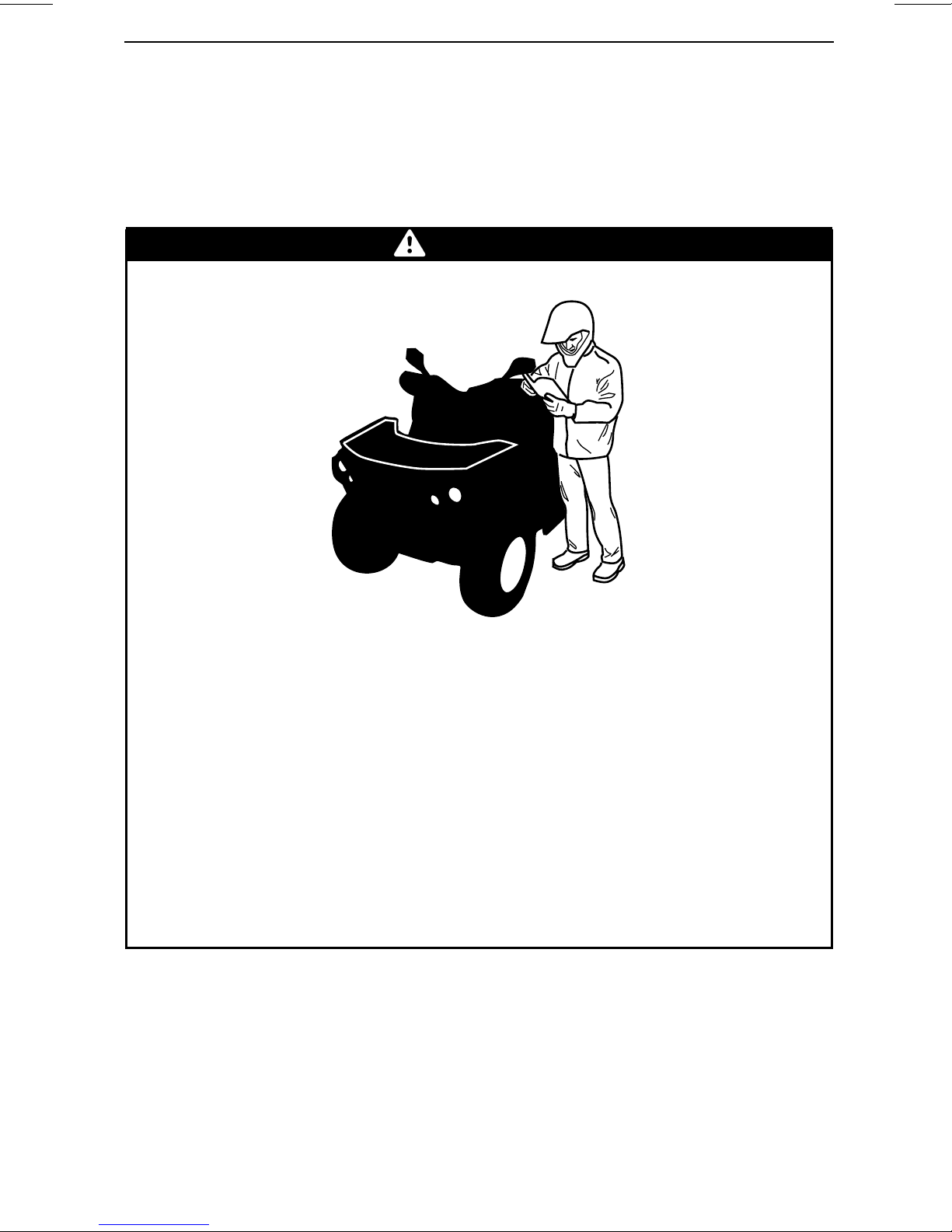
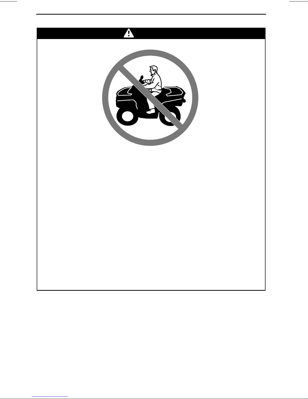
WARNING
POTENTIAL HAZARD
Operating this vehicle without proper instruction.
WHAT CAN HAPPEN
The risk of an accident is greatly increased if the operator does not know
how to operate this vehicle properly in different situations and on different
types of terrain.
HOW TO AVOID THE HAZARD
Beginning and inexperienced operators should c
They should then regularly practice the skills learned in the course and the
operating techniques described in this Operator's Guide.
For more information about the training course, contact an authorized
Can-Am dealer.
omplete a training course.
________
SAFETY INF
ORMATION
________
11
Page 14
OPERATION WARNINGS
V00A01Q
POTENTIAL HAZARD
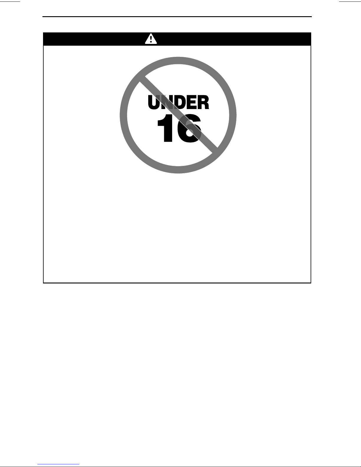
WARNING
Failure to follow the age recommendations for this vehicle.
WHAT CAN HAPPEN
A lack of respect for this age recommendation can lead to severe injury or
death of the child.
Even though a child may be within the age group for which this vehicle is
recommended, he may not have the skills, abilities, or jud
operate this vehicle safely and may be involved in a serious accident.
HOW TO AVOID THE HAZARD
No one under 16 should operate this vehicle.
gment needed to
12
_______
SAFETY I
NFORMATION
________
Page 15
POTENTIAL HAZARD
OPERATION WARNINGS
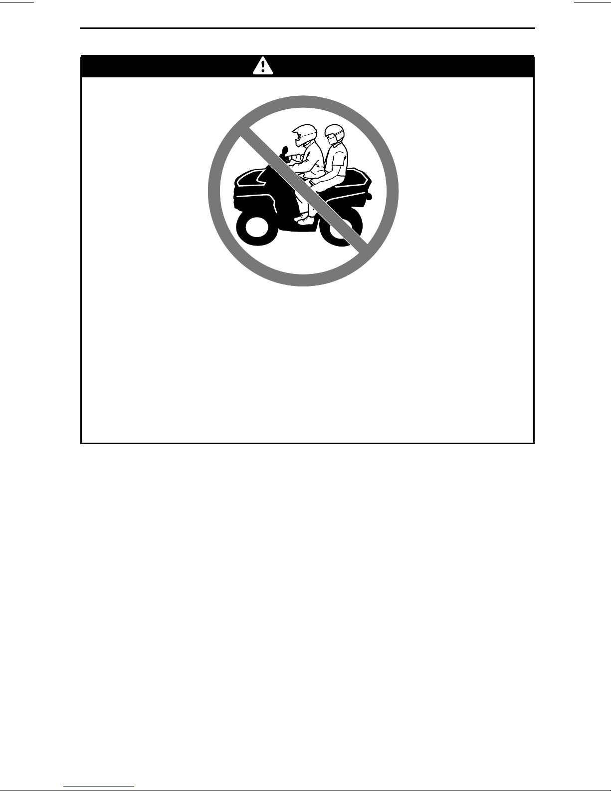
WARNING
Carrying a passenger on this vehicle.
WHAT CAN HAPPEN
Greatly reduces your ability to balance and control this veh
Could cause an accident, resulting in harm to you and/or your passenger.
HOW TO AVOID THE HAZARD
Never carry a passenger. Even with a long seat that provides unrestricted
operator movement, it is not designed nor intended to carry passenger(s).
icle.
________
SAFETY INF
ORMATION
________
13
Page 16
OPERATION WARNINGS
POTENTIAL HAZARD
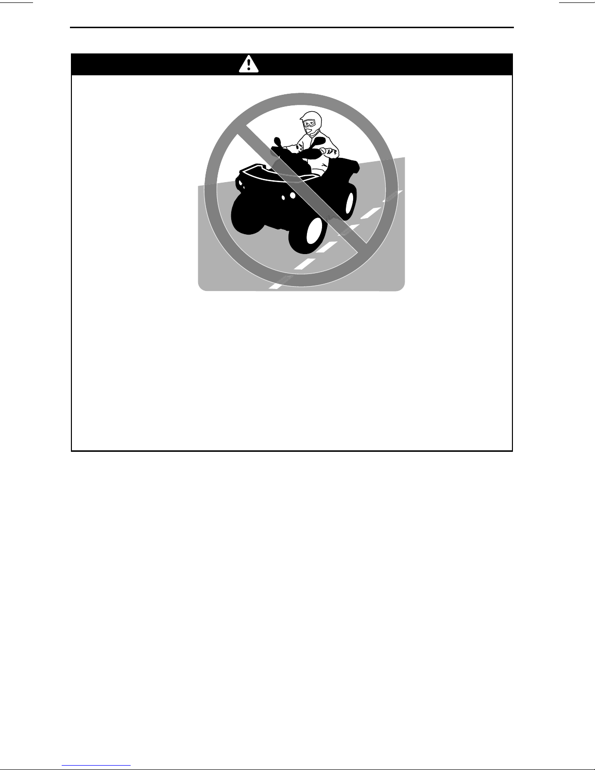
WARNING
Operating this vehicle on paved surfaces.
WHAT CAN HAPPEN
The tires are designedfor off-roaduse only, notfor use on pa
surfaces may s eriously affect handling and control of this vehicle, and may
cause the vehicle to go out of control.
HOW TO AVOID THE HAZARD
Never operate this vehicle on any paved surfaces, including sidewalks,
driveways, parking lots and streets.
vement. Paved
14
_______
SAFETY I
NFORMATION
________
Page 17
POTENTIAL HAZARD
OPERATION WARNINGS
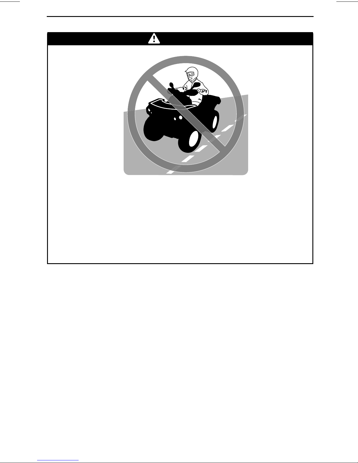
WARNING
Operating this vehicle on public streets, roads or highways.
WHAT CAN HAPPEN
You can collide with another vehicle.
HOW TO AVOID THE HAZARD
Never operate this vehicle on any public street, road or highway, even a dirt
or gravel one. In many states or provinces it is illegal to operate this vehicle
on public streets, roads or highways.
________
SAFETY INF
ORMATION
________
15
Page 18
OPERATION WARNINGS
POTENTIAL HAZARD
WARNING
Riding this vehicle without wearing an approved helmet, eye protectionand
protective clothing.
WHAT CAN HAPPEN
The following items concern all ATV's operator:
– Riding without an approved helmet increases the chances of a severe
head injury or death in the event of an accident.
– Riding without eye protection can result in an accident and increases the
chances of a severe injury in the event of an accident.
– Riding without protective clothing increase
in the event of an accident.
HOW TO AVOID THE HAZARD
Always wear an approved helmet that fits properly. You should also wear:
– Eye protection (goggles or face shield)
– Gloves and boots
– Long sleeved shirt or jacket
–Longpants.
s the chances of severe injury
16
_______
SAFETY I
NFORMATION
________
Page 19
V00A07Q
POTENTIAL HAZARD
OPERATION WARNINGS
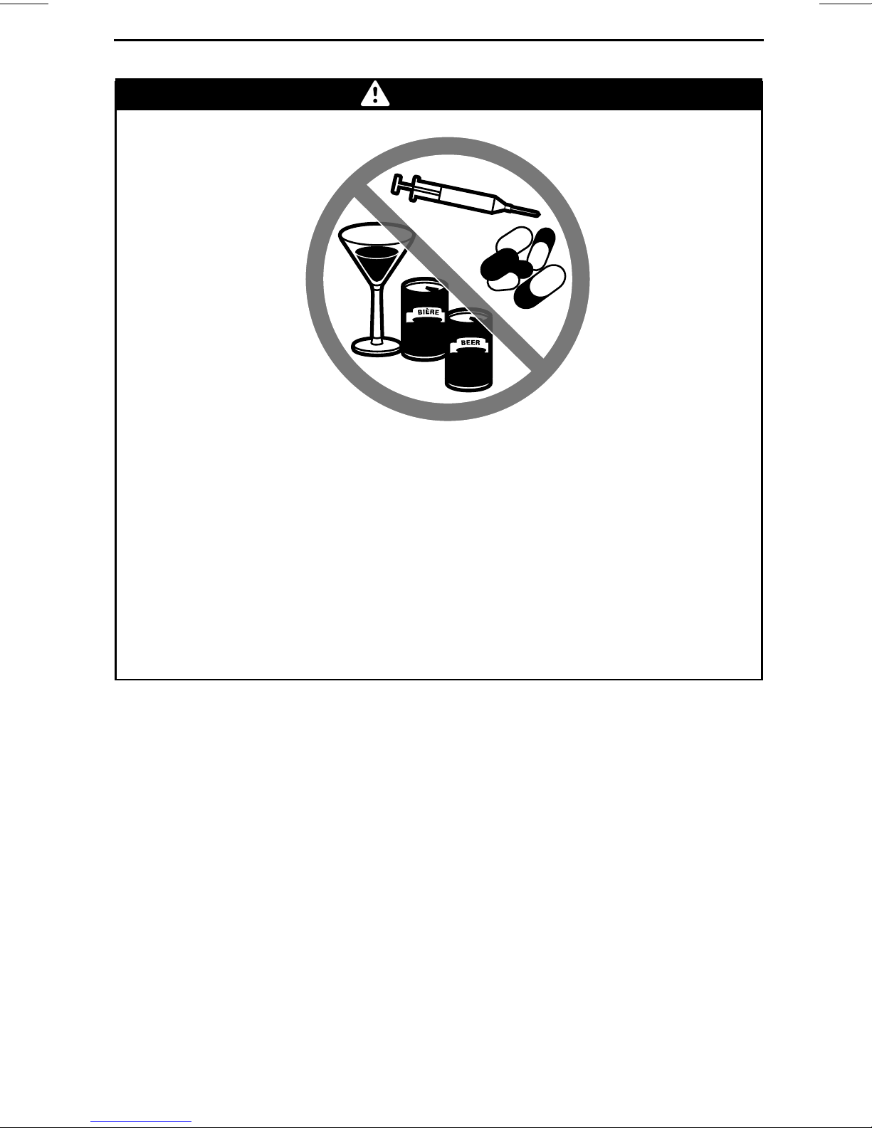
WARNING
Using this vehicle with drugs or alcohol.
WHAT CAN HAPPEN
Could seriously affect your judgment.
Could cause you to react more slowly.
Could affect your balance and perception.
Could result in an accident or death.
HOW TO AVOID THE HAZARD
Never use this vehicle with drugs or alcohol.
________
SAFETY INF
ORMATION
________
17
Page 20
OPERATION WARNINGS
V00A08Q
POTENTIAL HAZARD
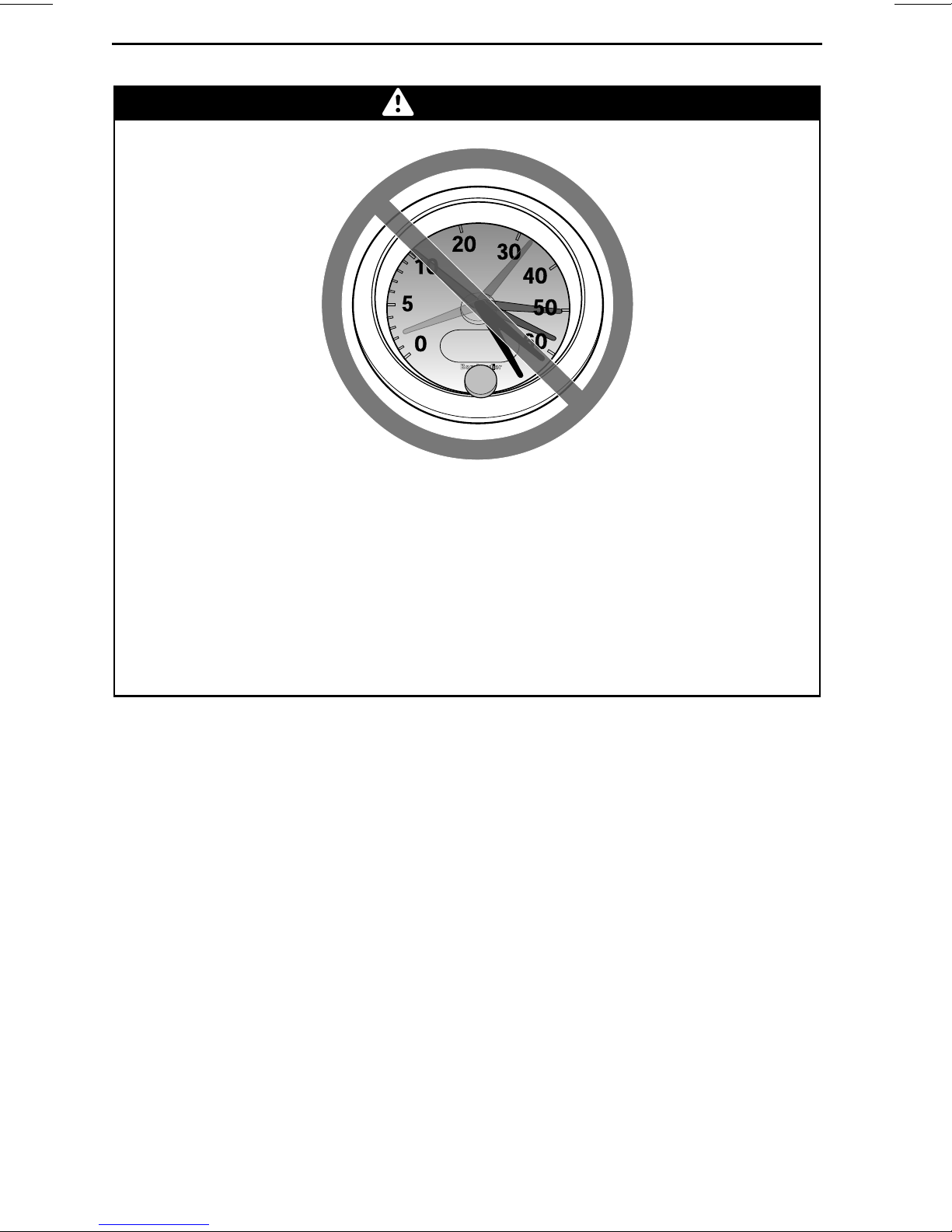
WARNING
Operating this vehicle at excessive speeds.
WHAT CAN HAPPEN
Increases your chances of losing control of the vehicle, which can result in
an accident.
HOW TO AVOID THE HAZARD
Always travel at a speed which is proper for the terrain, visi
ating conditions, and your experience.
bility and oper-
18
_______
SAFETY I
NFORMATION
________
Page 21

POTENTIAL HAZARD
OPERATION WARNINGS
WARNING
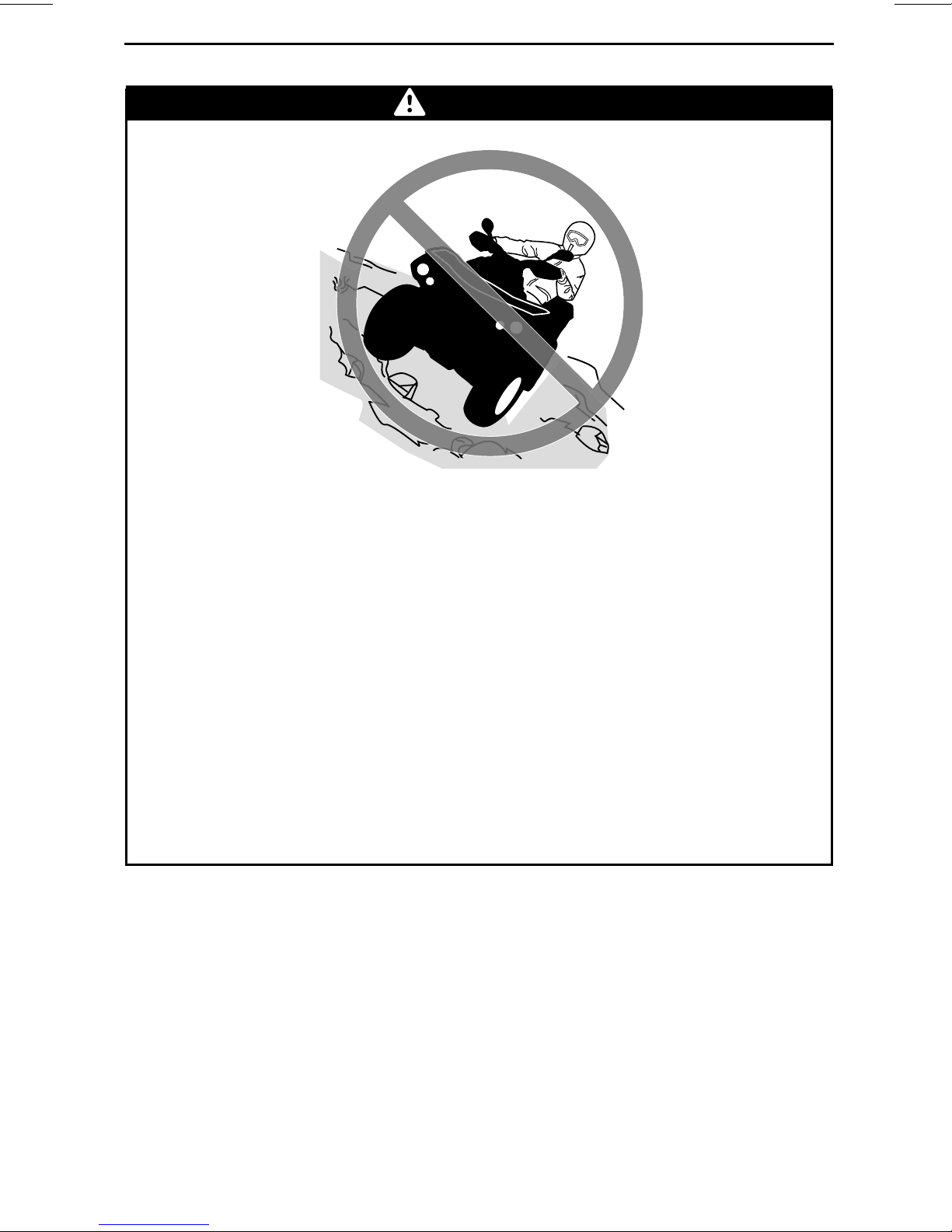
Attempting wheelies, jumps and other stunts.
WHAT CAN HAPPEN
Increases the chance of an accident, including an overturn.
HOW TO AVOID THE HAZARD
Never attempt stunts, such as wheelies or jumps. Do not try to show off.
WARNING
POTENTIAL HAZARD
Failure to inspect the vehicle before operating.
Failure to properly maintain the vehicle.
WHAT CAN HAPPEN
Increases the possibility of an accident or equipment damage.
HOW TO AVOID THE HAZARD
Always inspect your vehicle every time prior to use it to make sure the vehicle is in safe operating condition.
Always follow the inspection and maintenance procedures and schedules
described further in this Operator's G uide.
________
SAFETY INF
ORMATION
________
19
Page 22
OPERATION WARNINGS
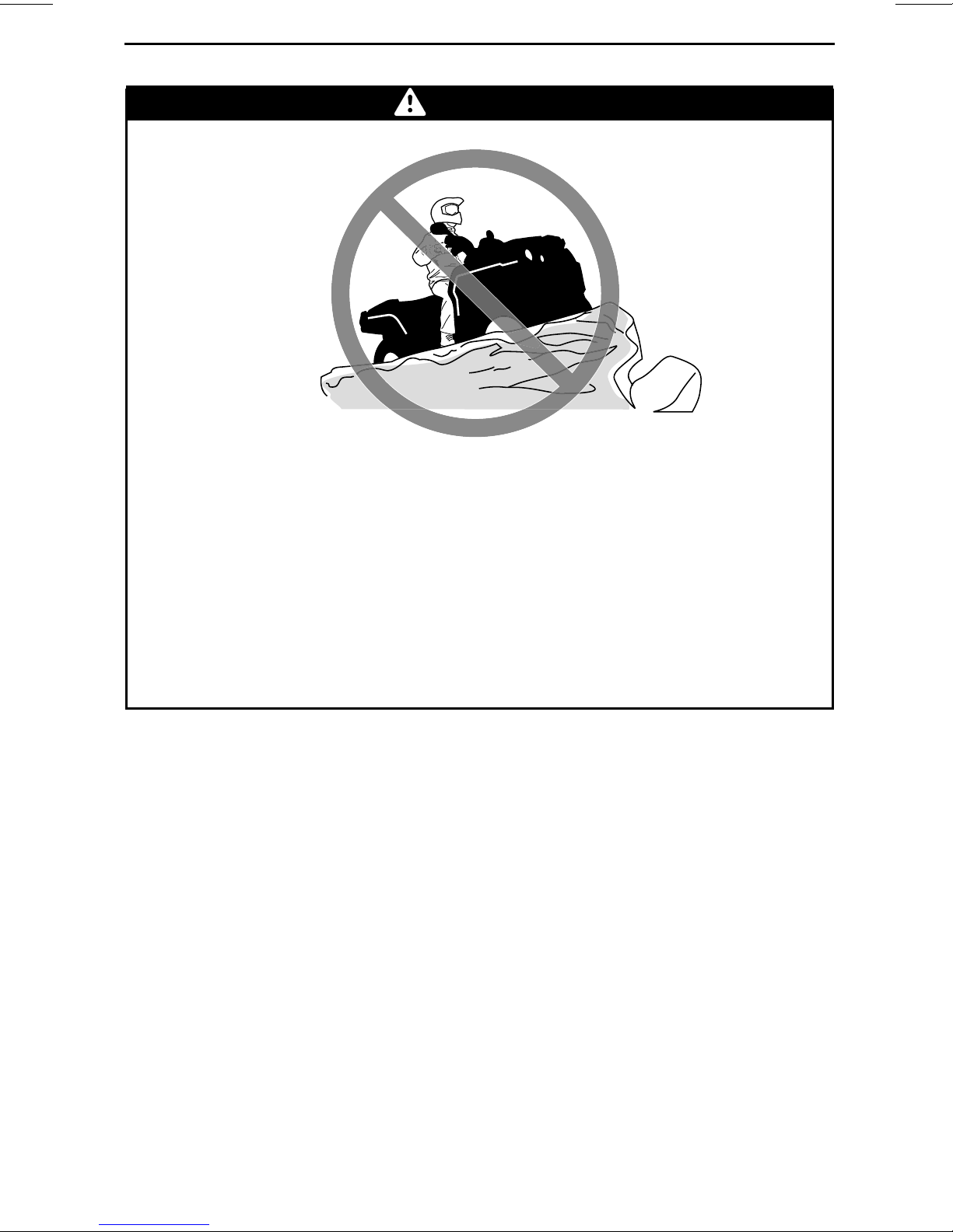
WARNING
POTENTIAL HAZARD
Riding on frozen waterways.
WHAT CAN HAPPEN
Breaking through the ice can lead to severe injury or death.
HOW TO AVOID THE HAZARD
Never ride this vehicle on a frozen surface before you are sure the ice is thick
enough and sound enough to support the vehicle and its load, as well as the
force that is created by a moving vehicle.
WARNING
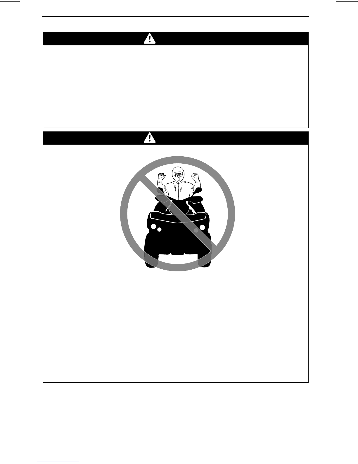
POTENTIAL HAZARD
Removing hands from handlebar or feet from the fo
tion.
WHAT CAN HAPPEN
Removing even one hand or foot can reduce your ability to control the vehicle or could cause you to lose your balance a
move a foot from the footrests, your foot or leg may come into contact with
the rear wheels, which could injure you or cause an accident.
HOW TO AVOID THE HAZARD
Always keep both hands on the handlebar and both feet on the footrests
during vehicle operation.
20
_______
SAFETY I
NFORMATION
nd fall off the vehicle. If you re-
otrests during opera-
________
Page 23
OPERATION WARNINGS
WARNING
POTENTIAL HAZARD
Failure to use extra care when operating this vehicle on unfamiliar terrain.
WHAT CAN HAPPEN
You can come upon hidden rocks, bumps, or holes, without enough time to
react.
Could result in the vehicle overturning or loss of control.
HOW TO AVOID THE HAZARD
Go slowly and be extra careful when operating on unfamiliar terrain.
Always be alert to changing terrain conditions when operating the vehicle.
________
SAFETY INF
ORMATION
________
21
Page 24
OPERATION WARNINGS
POTENTIAL HAZARD
WARNING
Failure to use extra care when operating on excessively rough, slippery or
loose terrain.
WHAT CAN HAPPEN
Could cause loss of traction or vehicle c ontrol, which could result in an accident, including an overturn.
HOW TO AVOID THE HAZARD
Do not operate o n excessively rough, slippery or loose terrain until you
have learned and practiced the skills necessary to control this vehicle on
such terrain.
Always be especially cautious on these kinds of terrain.
22
_______
SAFETY I
NFORMATION
________
Page 25

POTENTIAL HAZARD
OPERATION WARNINGS
WARNING
Turning improperly.
WHAT CAN HAPPEN
Vehicle could go out of control, causing a collision or overturn.
HOW TO AVOID THE HAZARD
Always follow proper procedures for turningas described further in this Operator's Guide. Practice turning at low speeds before attempting to turn at
faster speeds.
Do not turn at excess ive spee d.
________
SAFETY INF
ORMATION
________
23
Page 26
OPERATION WARNINGS
WARNING
POTENTIAL HAZARD
Operating on excessively ste ep hills.
WHAT CAN HAPPEN
The vehicle can overturn more easily on extremely steep hills than on level
surfaces or small hills.
HOW TO AVOID THE HAZARD
Never operate this vehicle on hills too steep for th
ties.
Practice on smaller hills before attempting large
e vehicle or for your a bili-
r hills.
24
_______
SAFETY I
NFORMATION
________
Page 27
POTENTIAL HAZARD
OPERATION WARNINGS
WARNING
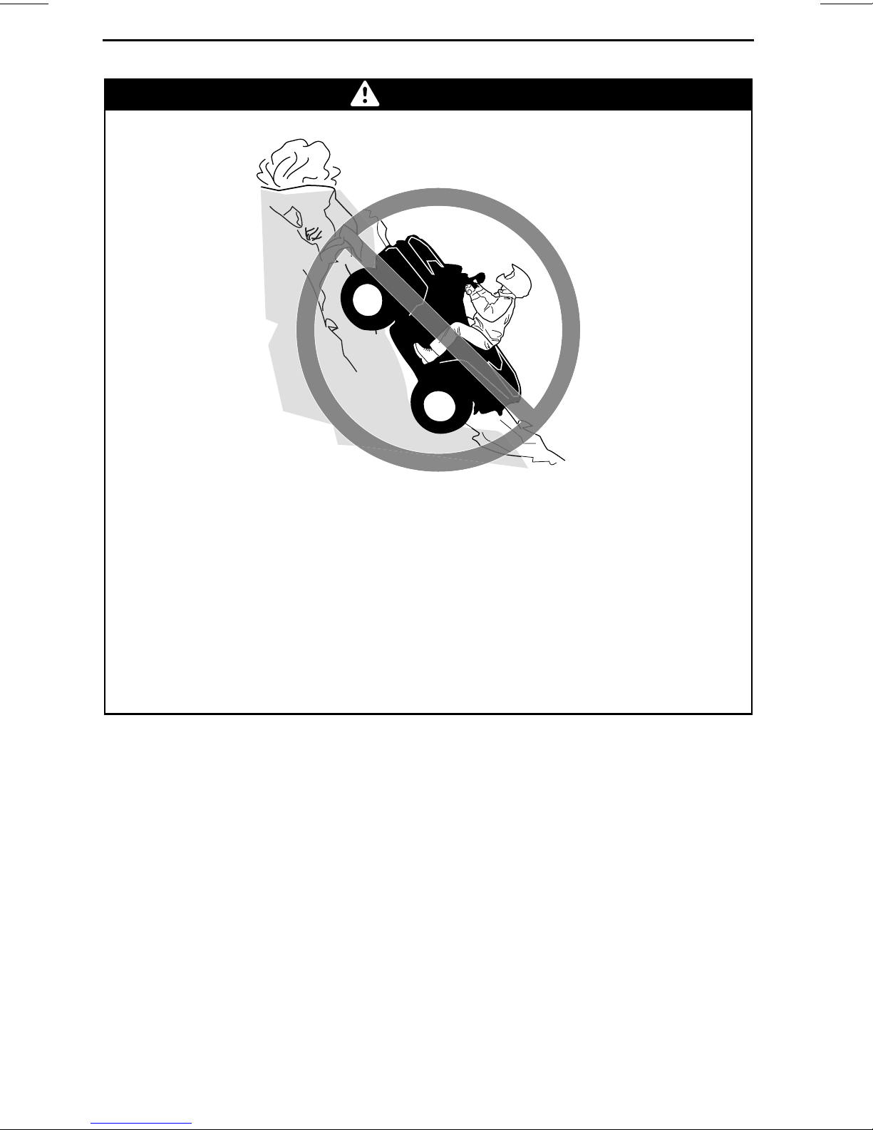
Climbing hills improperly.
WHAT CAN HAPPEN
Could cause loss of control or cause vehicle to overturn.
HOW TO AVOID THE HAZARD
Always follow proper procedures for climbing hills as described further in
this Operator's Guide.
Always check the terrain carefully before you start u p any hill.
Never climb hills with excessively slippery or loose surfaces.
Shift your weight forward.
Never open the throttle suddenly or make sudden gear changes. The vehi-
cle could flip over backwards.
Never go over the top of any hill at high speed. An obstacle, a sharp drop, or
another vehicle or person could be on the other side of th
e hill.
________
SAFETY INF
ORMATION
________
25
Page 28
OPERATION WARNINGS
POTENTIAL HAZARD
WARNING
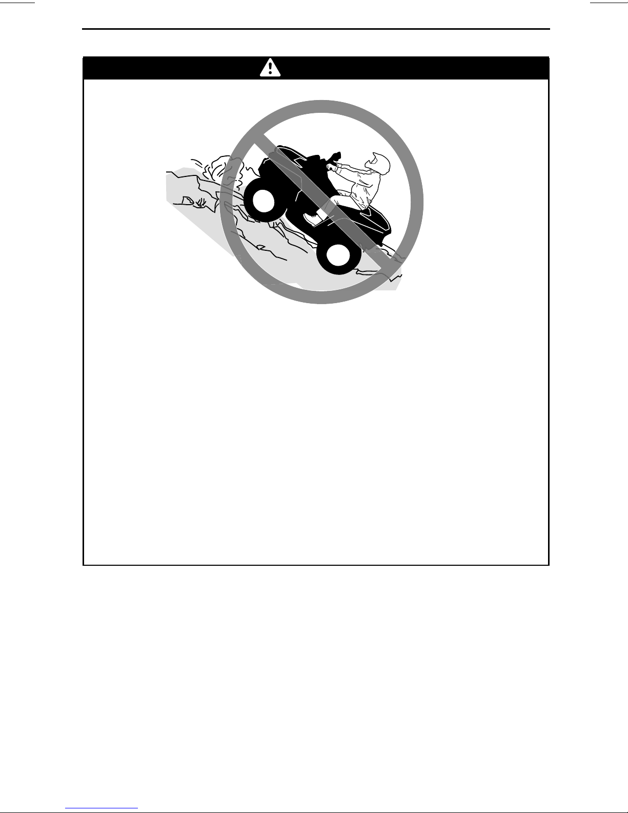
Going down a hill improperly.
WHAT CAN HAPPEN
Could cause loss of control or cause vehicle to overturn.
HOW TO AVOID THE HAZARD
Always follow proper procedures for going down hills as descr
in this Operator's Guide.
NOTE: A special technique is required when braking as you go
Always check the terrain carefully before you start down any hill.
Shift your weight backward.
Never go down a hill at high speed.
Avoid going down a hill at an angle which would cause the vehicle to lean
sharply to one side. Go straight down the hill where pos
sible.
ibed further
down a hill.
26
_______
SAFETY I
NFORMATION
________
Page 29
POTENTIAL HAZARD
OPERATION WARNINGS
WARNING
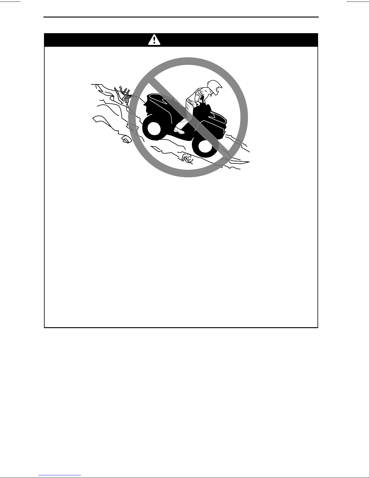
Improperly crossing hills or turning o n hills.
WHAT CAN HAPPEN
Could cause loss of control or cause vehicle to overturn.
HOW TO AVOID THE HAZARD
Never attempt to turn the vehicle around on any hilluntil youh
the turning technique as described further in this Operator's Guide on level
ground. Be very careful when turning on any hill.
Avoid crossing the side of a steep hill if possible.
When crossing th e side of a hill:
Always follow proper procedures as described further in this Operator's
Guide.
Avoid hills with excessively slippery or loose surfaces.
Shift your weight to the uphill side of the vehicle.
ave mastered
________
SAFETY INF
ORMATION
________
27
Page 30

OPERATION WARNINGS
WARNING
POTENTIAL HAZARD
Stalling, rolling backwards or improperly dismountingwhile climbing a hill.
WHAT CAN HAPPEN
Could result in vehicle overturning.
HOW TO AVOID THE HAZARD
Use proper gear and maintain steady speed when climbing a hill.
If you lose all f o rward s p eed:
Keep your weight uphill. Never open the throttle suddenly or make sudden
gear changes. The vehicle could flip over backwards.
Apply the brakes.
Lock parking brake after you have stopped.
Dismount on uphill side, or to a side if pointed straight uphill.
If you begin rolling backwards:
Keep your weight uphill. Never open the throttle suddenly or make sudden
gear changes. The vehicle could flip over backwards.
Never apply the rear brake while rolling backwards.
Apply the front brake gradually.
When fully stopped, apply rear brake as well and lock parking brake.
Dismount on uphill side, or to a side if pointed straight uphill.
Turn the vehicle around and remount, following the procedure described
further in this Operator's Guide.
28
_______
SAFETY I
NFORMATION
________
Page 31

POTENTIAL HAZARD
OPERATION WARNINGS
WARNING
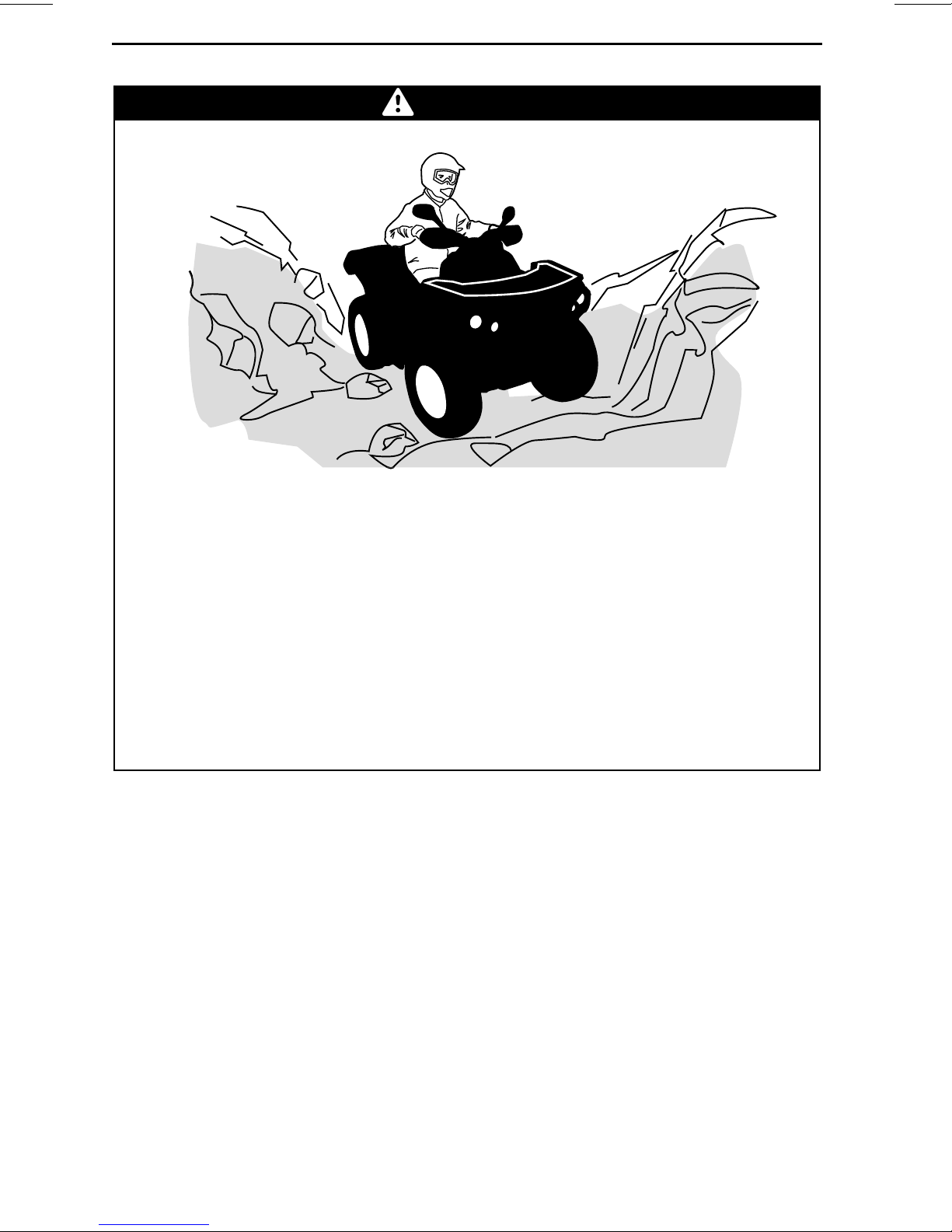
Improperly operating over obstacles.
WHAT CAN HAPPEN
Could cause loss of control or a collision.
Could cause the vehicle to overturn.
HOW TO AVOID THE HAZARD
Before operating in a new area, check for obstacles.
Never attempt to ride over large obstacles, such as large rocks o
trees.
When you go over obstacles, always follow proper proced
further in this Operator's Guide.
ures as described
r falle n
________
SAFETY INF
ORMATION
________
29
Page 32

OPERATION WARNINGS
POTENTIAL HAZARD
WARNING
Skidding or sliding improperly.
WHAT CAN HAPPEN
You may lose control of this vehicle.
You may also regain traction unexpectedly, which may cause the vehicle to
overturn.
HOW TO AVOID THE HAZARD
Learn to safely control skidding or sliding by practicing at low speeds and
on level smooth terrain.
On extremely slippery surfaces, such as ice, go slowly and be very cautious
in order to reduce the chance of skidding or sliding out of control.
30
_______
SAFETY I
NFORMATION
________
Page 33

POTENTIAL HAZARD
OPERATION WARNINGS
WARNING
Operating this vehicle through deep or fast flowing water.
WHAT CAN HAPPEN
Tires may float, causing lossof traction and loss of control, which could lead
to an accident.
HOW TO AVOID THE HAZARD
Never operate this vehicle in fast flowing water or in water deeper than that
specified further in this Operator 's Guide.
Check water depth and current before you attempt to cross any water. Water should not go above footrests.
Remember that wet brakes may have reduced stopping ability. Test your
brakes after leaving water. If necessary, apply them several times to let
friction dry out the pads.
________
SAFETY INF
ORMATION
________
31
Page 34

OPERATION WARNINGS
POTENTIAL HAZARD
WARNING
Operating this vehicle with improper tires, or with improper or uneven tire
pressure.
WHAT CAN HAPPEN
Use of improper tires on this vehicle, or operation of this ve
improper or uneven tire pressure, may cause loss of control, tire blow outs,
tire to move around on its rim, and increases the risk of an accident.
HOW TO AVOID THE HAZARD
Always use the size and type of tires specified further in thi
Guide for t his vehicle.
Always maintainproper tire pressure as described fu
Guide.
Always repl ac e wheels or tires that are damaged.
rther in this Operator's
hicle with
s Operator's
32
_______
SAFETY I
NFORMATION
________
Page 35

POTENTIAL HAZARD
OPERATION WARNINGS
WARNING
Operating this vehicle with improper modifications.
WHAT CAN HAPPEN
Improper installation of accessories or modification of this vehicle may
cause changes in handling which in some situations could lead to an accident.
HOW TO AVOID THE HAZARD
Never modify this vehicle through improper installation or use of accessories. All parts and accessories added to this vehicle should be approved
by BRP and should be installed and used according to
have questions, consult an authorized Can-Am dealer.
Modification of the vehicle to increase speed and p
the terms and conditionsof yourvehicle's limitedwarranty. Inaddition, certain modifications including the removal of engine or exhaust components
are illegal under most laws.
instructions. If you
erformance may violate
________
SAFETY INF
ORMATION
________
33
Page 36

OPERATION WARNINGS
POTENTIAL HAZARD
WARNING
Overloading this vehicle or carrying or towing cargo improperly.
WHAT CAN HAPPEN
Could cause changes in vehicle handling which could lead to an accident.
HOW TO AVOID THE HAZARD
Never exceed the stated load capacity for this vehicle including operator as
well as other loads and added accessories.
Cargo should be properly distributed and securely attached.
Reduce speed when carrying cargo. Allow greater distance for braking.
Always follow the instructions in this Operator's Guide for carrying cargo.
34
_______
SAFETY I
NFORMATION
________
Page 37

OPERATION WARNINGS
WARNING
V03M01Q
POTENTIAL HAZARD
Transporting flammable or dangerous material can lead to explosions.
WHAT CAN HAPPEN
This can cause serious injury or death.
HOW TO AVOID THE HAZARD
Never transport flammable or dangerous material.
________
SAFETY INF
ORMATION
________
35
Page 38

RIDING THE VEHICLE
To fully appreciate the p lea su re s and excitement of riding this vehicle, there are
some basic rules and tips that you MUST follow. Some may be new to you while
others may be common sense or obvious.
Please take the time to study this Operator's Guide and all on-product safety
labels as well as the
completely describe what you should know about this vehicle before riding it.
Whether you are a new user or an experienced rider, it is important for your
personal safety that you know the controls and features of this vehicle. Equally
important is knowing how to properly ride.
This is a high performance ATV for off-road use only. Inexperienced riders may
overlook risks and be surprised by the specific behavior of this ATV in any terrain
condition.
Persons with cognitive or physical impairm e nts or who are high risk takers have an
increased exposure to overturns or collisions which may result in injury including
death.
Not all vehicles are the same. Each has its own unique performance characteristics, controls and features. Each will ride and handle differently.
Become co mpletely familiar with the ope rational controls and the ge ne ral operation of the vehicle before venturing into off road conditions. Practice driving in a
suitable area free of hazards and feel the response of each control. Drive at low
speeds. Higher speeds require greater experience, knowledge and suitable riding
conditions.
SAFETY DVD
video that came with this vehicle. They more
Riding conditions vary from place to place. Each is subject to weather conditions
which may radically change from time to time and from season to season.
Riding on sand is different than riding on snow or through forests or marshes.
Each location may require a greater d eg ree of awarenes s and skills. Show good
judgement. Always proceed with caution. Please do not take any unnecessary
risks that could leave you stranded or possibly injured.
Never assume that the vehicle will go everywhere safely. Sudden changes in terrain caused by holes, depressions, banks, softer or harder “ground” or other irregularities may cause the vehicle to topple or become unstable. To avoid this, slow
down and always observe the terrain ahead. If the vehicle does begin to topple or
tip over, the best advice is to immediately get off... AWAY from the direction of the
tip over!
While reading this Operator’s Guide, remember that:
Indicates a potential hazard that, if not avoided, could result in serious
injury or dea t h.
36
_______
WARNING
SAFETY I
NFORMATION
________
Page 39

RIDING THE VEHICLE
Pre-Ride Inspection
WARNING
Perform a pre-ride inspection before each ride to detect potential problems
during operation. The pre-ride inspection can help you monitor wear and
deterioration before they become a problem. Correct any problems that
you discover to reduce the risk of a breakdown or crash. See an authorized
Can-Am dealer if necessary.
Before using this vehicle, the operator should always:
– Apply parking brake and check if it operates properly.
– Check tire pressure and condition.
– Check wheels and bearings for wear and damage.
– Check location of controls and ensure they work properly.
– Verify if steering operates freely.
– Activate throttle control lever several times to ensure it operates freely. It must
return to idle position when released.
– Activate the brake lever and brake pedal to make sure the brakes fully apply.
They must fully return when released.
– Ensure front brake lever position is adjusted to suit drivers hand.
– Check all brake line fittings for tightness and against leaks.
– With parking brake correctly applied, activate the clutch lever. It must fully re-
turn when released.
– Check drive chain for ad justment an d lubrication.
– Check sprockets for wear and damages.
– Check tightening of rear axle fasteners.
– Check swing arm, if any late ral play is detected DO NOT USE THE VEHICLE.
– Check fuel, oil and coolant levels.
– Check for oil leaks on the engine, oil tank and transmis sion.
– Check radiator cleanliness.
– Clean headlights and taillight.
– Ensure seat is properly latched.
– Look and feel for loose parts while engine is off. Check fasteners.
– Ensure the path of travel is free of persons and obstacles.
– Check operation of ignition switch, engine start button, emergency engine stop
switch, headlights, taillig ht and indicator ligh ts.
– Start engine, remove parking brake and drive forward slowly a few feet then ap-
ply all brakes individually to test them.
Correct any problem you m ay have found before riding. See an authorized
Can-Am dealer if necessary.
________
SAFETY INF
ORMATION
________
37
Page 40

RIDING THE VEHICLE
Clothing
Actual weather conditions should help you decide how to dress. However, it
is important that the operator always wears the appropriate protective clothing
and apparel, including an approved helmet, eye protection, boots, gloves, a long
sleeved shirt and pants. This type of clothing will provide you protection from
some of the minor hazards you m ay encounter en route. The operator must
never wear loose c lothing such as a scarf that may get entangled in the vehicle or
on tree branches and shrubs. Depending on conditions, antifogging goggles or
sunglasses may be required. Different colored lenses available for goggles or sun
glasses help you distinguish terrain variations. Sunglasses should only be worn
during the daytime.
Approved
helmet
Eye protection
Rigid chin
guard
V00A0RN
Chest
protector
Long
sleeves
Gloves
Long, sturdy
pants
Boots
Carrying Passenger
This vehicle is designed specifically to carry an operator only. This vehicle is not
designed nor intended t
the stability and your control of the vehicle.
Carrying Loads
Never load cargo on this v ehicle.
38
_______
o carry passenger(s). Carrying passenger(s) may affect
SAFETY I
NFORMATION
________
Page 41

RIDING THE VEHICLE
Recreational Riding
Respect the rights and limitations of others. Stay away from areas designated
for other types of off road use. This includes snowmobile trails, equestrian trails,
cross country ski trails, mountain bike trails etc. Never a ssume there are no other
usersonthetrail. Alwaysstaytothecompleterightofthetrailanddonotzigzag
toonesideofthetrailthentheother. Bepreparedtostoporpullofftothesideif
another trail user appears in front of you.
Join a local ATV club. It will provide you with a map and advice or inform you where
you can ride. If a club does not exist in your area, help to s tart one. Group riding and
club activities provide a pleasurable, social experience.
Always keep a safe distance from other riders. Your judgment of speed, terrain conditions, weather, mechanical condition of your vehicle and the “trust in
judgment” you have in others around you will help you make a better choice of
appropriate safe distance. This vehicle, like any other motorized vehicle, cannot
stop “on a dime”.
Before you ride, tell someone where you are planning to travel and your expected
time of return. Never consume alcohol or drugs before or while riding!
Depending on the length of your ride, carry additional tools or emergency equipment. Find out where you can get additional gasoline and oil. Be prepared for the
possible conditions you may encounter. An emergency first aid kit should always
be a consideration.
Environment
One of the benefits of this vehicle is that it can take you off the beaten path away
from most communities. However, you should always respect nature
rights of others to enjoy it. Do not ride in environmentally sensitive areas. Do not
drive over forest crops or shrubs... nor cut down trees or take down fencing... nor
spin your wheels and destroy the terrain. “Tread Lightly”.
This vehicle can cause OHV wildfires if debris builds up ne ar the exhaust or other
engine hot spots and ignites then falls off into dry gra
through muskeg or tall grass, where debris can build up. Should you ride in those
areas, inspect and remove all debris from your engine and hot spots.
Chasing wildlife is in many areas illegal. Wildlife can die of exhaustion after be ing
chased by a motorized vehicle. If you encounter animals on the trail, stop and observe quietly and with caution. It will be one of the b
Observe the rule... “what you t ake in, carry out”. Do not litter. Do not start campfires unless you have permission to do so... an
The hazards you may create on the trail m ay cause injury to others or yourself, even
at a later date.
Respect farm lands. Always obtain the permission of the landowner before riding
on private land. Respect crops, farm animals and property lines. If you come to a
closed a gate, close it again behind you.
Finally, do not pollute streams, lakes or rivers and do not modify the engine or muffling system, or remove any of its compo
nents.
d then only... away from dry areas.
ss. Avoid riding in wet areas,
etter memories of your life.
and the
________
SAFETY INF
ORMATION
________
39
Page 42

RIDING THE VEHICLE
Design Limitation
Although the vehicle is exceptionally rugged for its class, it is still a light vehicle by
definition and its operation must be restricted to its proper purpose.
The addition of we igh t to any part of the veh icle changes its gravitational stability
and modifies its performance.
Off-Highway Operation
The very nature of off-highway operation is dangerous. Any terrain, which has
not been specially prepared to carry vehicles, presents an inherent danger where
angularity, terrain substance and exact steepness are unpredictable. The terrain
itself presents a continual element of danger, which must be knowingly accepted
by anyone venturing over it.
An operator who takes a vehicle off-road should always exercise the utmost care in
selecting the safest path and keeping close watch on the terrain ahead of him. On
no account should the vehicle be operated by anyone who is not completely familiar with the driving instructions applicable to the vehicle, nor should it be operated
on steep or treacherous terrain.
General Operating and Safety Precautions
Care, caution, experience and driving skill are the best precautions against the hazards of vehicle operation.
Whenever there is the slightest doubt that the vehicle can safely negotiate an obstacle or a particular piece of terrain, always choose an alternate rou
In off-road operation, power and traction, not speed, are important. Never drive
faster than visibility and your ow n ability to select a safe rou te permi
Constantly watch the terrain ahead for sudden changes in slopes or obstacles,
such as rocks or stu m ps, that may cause loss of stability, resulting in t
rollover.
Never ope rate the v eh icle if the controls do not function norm
When stopped or parked, always apply the parking brake. This is especially impor-
tant when parking on a slope. On very steep inclines or if the ve
cargo, the wheels should b e blocked using rocks or bricks. Remember to turn the
fuel valve to the closed p os ition.
Uphill Driving
Due to configuration, this vehicle has excellent clim
tip over is possible before traction is lost. For example, its common to encounter
terrain situations where the top of the hill has erode d to a po int that the hill peak
rises very sharply. The vehicle can readily negotia
in doing so, when the front of the vehicle is driven to a point that the vehicle's
balance changes rearward tip over can occur.
bing ability, so much so that
te such a condition, however,
ally.
te.
t.
ip over or
hicle is carrying
The same situation may apply if an embedded object causes the front of the vehicle to climb more than desired. If such a situation occurs take an alternate route.
Be aw are of side hilling dangers when d oin g s
It is also wise to know the terrain condition on the other side of the hill or bank. All
too often there exists a sharp drop-off that
40
_______
SAFETY I
o.
is impossible to negotiate or descend.
NFORMATION
________
Page 43

RIDING THE VEHICLE
Downhill Driving
This vehicle can climb steeper slopes that it can descend safely. Therefore, it is essentialtoassurethatasaferouteexiststodescendaslopebeforeyouclimbit.
Decelerating while negotiating a slippery downhill slope could “toboggan” the vehicle. Maintain steady speed and/or accelerate slightly to regain control.
Side Hilling
Whenever possible, such operation should be avoided. If necessary, do so with
extreme caution. Sid e hilling on ste ep inclines could result in rollover. In addition,
slippery or unfirm surfaces could result in uncontrollable side sliding. Do not attempt to turn the vehicle downhill with the slide. Avoid all objects or depressions
that will intensify the raising of one side of the vehicle higher than the other, thus
causing rollover.
WARNING
Do not try to stop or save the vehicle from damage.
WARNING
Be careful when loading and transporting liquid reservoirs. They can affect
vehicle stability whenside hillingby pullingdownhill and increasing the risk
of a roll over.
Drop-Offs
This vehicle will “bottom-out” and usually stop if either the front or rear wheels are
driven over a drop-off. If the drop is sharp or deep, the vehicle will nose dive and tip
over.
WARNING
Avoid negotiating drop-offs. Reverse and select an alternate route.
Riding on Snow Covered Surfaces
When p erforming the pre-ride inspection, pay special attention to locations on the
vehicle wh ere snow and/or ice accum u lations may obstruct visibility of the tail
lamp, clog ventilation openings, block the radiator and fan, and interfere with the
movement of control levers, switches and brake pedal. Before starting with your
ATV check the steering, throttle and brake lever and pedal controls for interfere nce
free operation.
Whenever an ATV is ridden on a snow covered drive path the tire grip is generally
reduced causing the vehicle to react differently to control inputs from the operator.
On low grip surfaces, the steering responses are not as crisp and precise, stopp ing
distances are lengthened and acceleration becomes sluggish. Slow down and do
not "gun" the throttle. This will only result in spinning of the tires and possibly in an
over steering slide of the vehicle. Avoid hard braking. This will possibly re sult in a
straight line slide of the vehicle. Again, the best advice is to safely reduce speed in
anticipation of a maneuver so to give yourself time and distance to regain total vehicle control before it spins out of your control.
________
SAFETY INF
ORMATION
________
41
Page 44

RIDING THE VEHICLE
As you drive your ATV over a loose snow c overed surface, snow dust will be
picked up in the wake turbulence of the moving vehicle and transporte d to contact
and accumulate or melt on some exposed components including rotating parts
like brake discs. Water, snow or ice may affect the response time of the brake
system of your ATV. Even when not required to reduce vehicle speed apply brakes
frequently to prevent ice or snow accumulation and to dry brake pads and discs.
While doing so in low risk driving situations you will test for grip level and keep
yourself alerted to how the vehicle reacts to your control inputs. Always keep
brake pedal, footrests, floor boards, brake and throttle levers free of snow and ice.
Frequently wipe snow off seat, handgrips, head and tail lamps.
The depth of the snow cover may hide rocks, tree stumps or other objects and if it
is wet may totally impede the drivability as the vehicle beco mes bogged down or
completely looses traction in slushy snow. Look far ahead and always be watchful
of any visible clues that might indicate the presence of such obstacles. In doubt
steer clear. Avoid driving on any frozen body of water before checking that the
ice will safely support the ATV, its riders and its load of cargo. Remember that a
given thickness of ice may be sufficient to support a snowmobile but not
of an identical weight because of the smaller load bearing surface of the four tire
contact patches as compared to that of a snowmobile track and skis.
Always remember that the vehicle handling an d stability is affected when riding
with a passenger. So never attempt maneuvers with a passenger that may cause
the vehicle to enter into a slide that if halted abruptly will result
the passen ge r and/or a vehicle roll or tipover.
in the ejection of
an ATV
To maximize comfort and avoid frostbite, always wear clot
equipment appropriate for the weather conditions you will be exposed to during
your ride.
At the end of each ride it is a g ood practice to clean the vehicle body and all moving
components (brakes, steering components, drivelines, controls, radiator fan etc.)
from any snow or ice accumulations. Wet snow will turn t
down period and become more difficult to remove at the next pre-ride inspection.
hing and ATV protective
o ice during the shut
Riding Techniques
Riding your vehicle too fast for the conditions may result in injury. Apply only
enough throttle to proceed safely. Statistics show that high speed turns usually
result in mishaps and injury. Always remember
weight alone may entrap you should it fall and pin you down.
This vehicle is not designed for jumping
impacts such as jumping. Performing “wheelies” can cause the vehicle to flip over
onto you. Both practices have a high risk for you a nd should be avoided at all times.
To maintain proper control it is strongly advised that you keep your hands on the
handlebar and within easy reach of all controls. The same holds true for your feet.
To minimize the possibility of any leg
at all times. Do not direct your toes outwards nor place your foot out to assist
turning as they can be hit or snagged by passing obstacles or may contact the
wheels.
nor can it, or you, absorb the energy of high
or foot injury, keep your feet on the footrests
that this vehicle is heavy! Its pure
Always use proper riding techniques to avoid vehicle overturns on hills and rough
terrain and in turns.
42
_______
SAFETY I
NFORMATION
________
Page 45

RIDING THE VEHICLE
vmo2012-012-520
Even though there is an adequate suspensions system on this vehicle there are
“washboard” or rough terrain conditions that will make you feel uncomfortable
and even cause back injury. “Posting” or riding in a crouched position will often
be required. Slow down and allow you r flexed le g s to absorb impact.
This vehicle is not designed for riding on roads or highways. In most places it is an
illegal practice. Ridin g your vehicle on roads or highways could cause a collision to
occur with another vehicle.
The tires of this vehicle are not suited for paved road use. Also this vehicle is
not equipped with a rear differential (rear wheels are always turning at the same
speed). For these reasons, pavement may seriously affect the handling and
control of the vehicle.
Riding on roads or soft shoulders may confuse other road users, especially if your
lights are on.
If you have to cross a road, the lead driver should get off his vehicle, then observe
and give directions to the other riders. The last person after crossing then a ssists
the lead driver to cross. Do not travel on sidewa lks. They are designated for
pedestrian use.
Water can be a unique hazard. If it is too deep the vehicle may “float” and topple.
Check the water depth and current before you attempt to cross any water. Water
should not go above the footrest. Be wary of slippery surfaces such as rocks,
grass, logs, etc., both in the water and on its banks. A loss of traction may occur.
Do not attempt to enter the water at high speed. The water will act as a brake and
could throw you off the vehicle.
________
SAFETY INF
ORMATION
________
43
Page 46

RIDING THE VEHICLE
vmo2012-012-524
Wet brakes w ill affect the braking ability of your vehicle. Mak e sure you dry the
brakes by applying them several times after the vehicle leaves the water, mud or
snow.
Mud or marsh lands may be encountered near water. Be prepared for sudden
“holes” or changes in depth. Similarly so, be watchful of hazards such as rocks,
logs, etc., partially covered by vegetation.
If your trip crosses frozen waterways, make sure that the ice is thick enough and
sound enough to support the total weight of yourself, the vehicle and its load. Be
ever watchful of open water... it is a sure indication that the ice thickness will vary.
If in doubt, do not attempt to cross.
Ice will also affect the control of the vehicle. Slow down and do not “gun” the
throttle. This will only result in spinning of the tires and possible tip over of the
vehicle. Avoid rapid braking. This again will possibly result in an uncontrolled slide
and tip over of the vehicle. Slush should be avoided at all times since it could block
the operation or controls of the vehicle.
Riding in snow ma y affect the brakes stopping ability. Safely reduce speed an d
allow greater distance for braking. Snow projection may cause ice build up or
snow accumulation on brake components and controls. A pply brakes frequently
to prevent ice or snow accumulation. Carefully inspect the brake system before
each ride and always k eep brake pedal, footrests, floor boards and brake levers
free of snow and ice.
Sand and riding on sand dunes or on snow is another unique experience but
there are some basic precautions that should be observed. Wet, deep or fine
sand/snow may create a loss of traction and cause the vehicle to slide, drop off
or become “bogged” down. If this occurs look for a firmer base. Again, the best
advice is to slow down and be watchful of the conditions.
When riding in sand dunes it is advisable to equip the vehicle with an antenna type
safety flag. This will help make your location more visible to others over the next
sand dune. Proceed carefully should you see another safety flag ahead. Since the
antenna type safety flag can snag and rebound on your body if caught, do not use it
in areas where there are low hanging branches or obstacles.
44
_______
SAFETY I
NFORMATION
________
Page 47

RIDING THE VEHICLE
Riding on loose stones or g r avel is very sim ila r to riding on ice. They will affect
the steering of vehicle... possibly causing it to slide and tip over especially at
high speeds. In addition, braking distance may be a affected. Remember that
“gunning” the throttle or sliding may cause loose stones to be ejected rearwards
into the path of another rider's way. Never do it deliberately.
vmo2012-012-525
If you do get into a slide or skid, it may help to turn the handlebar into the direction
of the skid until you regain control. Never jam the brakes and lock the wheels.
Respect and follow all posted trail signs. They are there to help you and others.
Obstacles in the “trail” should be traversed with caution. This includes loose
rocks, fallen trees, slippery surfaces, fences, posts, and embankments and
depressions. You should avoid them whenever possible. Remember that some
obstacles are too large or dangerous to cross and should be avoided. Small rocks
or fallen trees may be safely crossed... approach at a 90° angle. Stand on the
footrests while keeping your knees flexed. Adjust speed without losing momentum and do not “gun” the throttle. Hold handlebar firmly. Place your body weight
rearwards and proceed. Do not try to lift the vehicle front wheels off the ground.
Be aware that the object may be slippery or may move while crossing.
When driving on hills or slopes two things are highly important... be prepared
for slippery surfaces or terrain variations and obstacles and... use proper body
positioning.
When stopped or parked always apply the parking device. This is especially important when parking on a slope. On very steep inclines or if the ATV is carring a cargo,
the wheels should be blocked using rocks or bricks.
________
SAFETY INF
ORMATION
________
45
Page 48

RIDING THE VEHICLE
Uphill
Before trying to climb a hill, keep these things in mind. Hill Climbing should only
be attempted by experienced operators. Start on shallow slopes. Always drive
straight uphill and keep your body weight forward t ow ards the top of th e hill.
Keep your feet on the footrests, shift your ATV into a lower gear and accelerate
before you start to climb. Try to keep a steady speed and go easy on the throttle
to avoid acceleration. Abrupt slope or terrain variatio n or rolling one wheel over
an obstacle could have a big impact on the stability as it will lift the front of the
vehicle increasing the risk of tipping over. Som e hills are too steep to safely stop or
recover from after an unsuccessful climbing attempt. Try to avoid steep inclines.
If you're not careful, you could tip over when going up hills. I f the hill is too steep
and you cannot proceed or the vehicle begins to roll backwards, apply the brake,
being careful not to slide. Dismount then use the “K” turn (while walking back,
next to the vehicle on the up hill side and with a hand on the brake lever, s lowly
back the rea r of the vehicle toward t he top of the hill then drive downhill). Always
walk or dismount on the upside of the slope while keeping clear of the vehicle and
its rotating wheels. Do not try to hold on to the vehicle if it begins to to
clear. Do not ride over the crest of the hill at high speed. Obstacles, including
sharp drop-offs, may exist.
pple. Stay
vmo2012-012-526
46
_______
SAFETY I
NFORMATION
________
Page 49

RIDING THE VEHICLE
Downhill
Keep your body weight rearwards. Stay seated. Apply the brake gradually to prevent skidding. Do not “coast” down the slope using solely engine compression or
in neutral gear.
Decelerating while negotiating a slippery downhill slope could “toboggan” the
vehicle. Maintain steady speed and/or accelerate slightly to regain control. Try
to avoid steep inclines. If you're not careful, you could tip over when going down
hills.
vmo2012-012-523
________
SAFETY INF
ORMATION
________
47
Page 50

RIDING THE VEHICLE
Side Hilling
This is one of the most risky types of riding sin ce it may drastic ally change the balance of the vehicle. It should be avoided wherever possible. If it is necessary to do
so however, it is important that you ALWAYS keep your body weight on the upside
of the slope... and be prepared to dismount on that side should the vehicle begin
to topple.
WARNING
Do not try to stop or save the vehicle from damage.
WARNING
Be careful when loading and transporting liquid reservoirs. They can affect
vehicle stability whenside hillingby pullingdownhill and increasing the risk
of a roll over.
vmo2012-012-527
While reading this Operator’s Guide, remember that:
Indicates a potential hazard that, if not avoided, could result in serious
injury or dea t h.
48
_______
WARNING
SAFETY I
NFORMATION
________
Page 51

IMPORTANT ON-PRODUCT LABELS
Hang Tag
This vehicle comes with a hang tag and labels containing important safety information.
Any person who rides this vehicle should read and understand this information before riding.
vmo2009-005-003_en
704901107
vmo2006-005-009_en
________
SAFETY INF
ORMATION
________
49
Page 52

IMPORTANT ON-PRODUCT LABELS
Vehicle Safety Labels
Read and understand all the safety labels on your vehicle.
These labels are affixed to the vehicle
for the safety of the operator or bystanders.
The following labels are on your vehicle
and they should be considered permanent parts of the vehicle. If missing or
damaged, they can be replaced free
of charge. See an authorized Can-Am
dealer.
NOTE: In the event of any d iscrepancy between this guide and the vehicle, the safety labels on the vehicle
have precedence over the labels in this
guide.
vmo2008-011-098_b
vmo2008-011-021_a
vmo2014-012-001_a
vmo2008-011-023_a
vmo2014-018-002_b
UNDERNEATH ACCESS COVER
50
_______
SAFETY I
NFORMATION
________
Page 53

vmo2009-003-004_en
LABEL 1
NEVER USE UNDER
THE INFLUENCE OF
DRUGS OR ALCOHOL.
IMPORTANT ON-PRODUCT LABELS
704902777A
LABEL 4
V01M02Z
LABEL 2
V02M05Y
LABEL 3
V01M07Z
LABEL 5
Improper tire pressure or
overloading can cause
loss of control, resulting
in SEVERE INJURY or
DEATH.
ALWAYS maintain proper tire pressure as shown.
NEVER set tire pressure below minimum. It could cause the tire to
disloge from the rim.
NEVER exceed the vehicle load capacity of 100 kg (220 lb)
Including weight of operator and accessories.
704901365
LOAD
UP TO
100 kg
(220 lb)
COLD TIRE PRESSURE
FRONT
MAX: 48.3 kPa (7 PSI)
MIN: 34.5 kPa (5 PSI)
REAR
MAX: 48.3 kPa (9 PSI)
MIN: 34.5 kPa (7 PSI)
LABEL 6 - DS 450™ X™ XC
________
SAFETY INF
ORMATION
________
51
Page 54

IMPORTANT ON-PRODUCT LABELS
Improper tire pressure or
overloading can cause
loss of control, resulting
in SEVERE INJURY or
DEATH.
ALWAYS maintain proper tire pressure as shown.
NEVER set tire pressure below minimum. It could cause the tire to
disloge from the rim.
NEVER exceed the vehicle load capacity of 100 kg (220 lb)
Including weight of operator and accessories.
704902001
LOAD
UP TO
100 kg
(220 lb)
COLD TIRE PRESSURE
FRONT
MAX: 68.9 kPa (10 PSI)
MIN: 55.2 kPa (8 PSI)
REAR
MAX: 62.1 kPa (9 PSI)
MIN: 48.3 kPa (7 PSI)
LABEL6-DS450™X™MX
vmo2010-010-100_a
LABEL 7
Compliance Labels
704903327
LOCATED ON RIGHT FRONT FENDER
704901438
LOCATED ON BOTTOM OF RH FRON T
FENDER
CAN ICES-2 / NMB-2
POWER
PUISSANCE
WET WEIGHT
POIDS EN ETAT
704904559
DE MARCHE
THIS VEHICLE IS AN ALL TERRAIN VEHICLE AND IS NOT INTENDED FOR USE ON PUBLIC ROADS.
CE VEHICULE EST UN VEHICULE TOUT TERRAIN QUI N'EST PAS DESTINÉ À ÊTRE UTILISÉ SUR
LES VOIES PUBLIQUES.
A704904559
kW
kg
TYPICAL - LOCATED ON RIGHT SIDE
MEMBER OF FRAME
ENGINE FAMILY
PERMEATION FAMILY
CERTIFICATION
STANDARD (FEL)
ENGINE DISPLACEMENT
EXHAUST EMISSION
CONTROL SYSTEM
BOMBARDIER RECREATIONAL PRODUCTS INC.
704903984
FAMILLE DE MOTEUR
FAMILLE DE PERMEATION
LIMITE DES ÉMISSIONS
DE LA FAMILLE
CYLINDRÉE
SYSTÈME DE CONTRÔLE
DES ÉMISSIONS
RENSEIGNEMENTS SUR LE DISPOSITIF ANTIPOLLUTION
CE VÉHICULE EST CERTIFIÉ POUR FONCTIONNER À L'ESSENCE SANS PLOMB ET IL
EST CONFORME AUX NORMES DE L'EPA ET DE LA CALIFORNIE AU NIVEAU
DES RÉGLEMENTATIONS DE L’ÉCHAPPEMENT ET DE L’ÉVAPORATION POUR LES VTT.
EMISSION CONTROL INFORMATION
THIS VEHICLE IS CERTIFIED TO OPERATE ON UNLEADED GASOLINE AND CONFORMS
TO U.S. EPA AND CALIFORNIA EMISSION / EVAP REGULATIONS FOR ATV.
SEE OPERATOR’S GUIDE FOR MAINTENANCE SCHEDULE
VOIR LE PROGRAMME D’ENTRETIEN DANS LE GUIDE DU CONDUCTEUR
TYPICAL - LOCATED ON LEFT SIDE MEMBER OF FRAME
While reading this Operator’s Guide, remember that:
.
704903984
Indicates a potential hazard that, if not avoided, could result in serious
injury or dea t h.
52
_______
WARNING
SAFETY I
NFORMATION
________
Page 55

Technical Information
Label
vmo2008-011-024_b
TYPICAL
1. D rive chain label
IMPORTANT ON-PRODUCT LABELS
DRIVE CHAIN MUST BE WELL ADJUSTED AND
LUBRIC ATED. FREE PL AY IS xx mm (x/x") WITH
DRIVER ON VEHICLE. SEE OWNERS MANUAL
FOR COMPLETE INSTRUCTIONS.
vmo2008-011-088_en
DRIVE CHAIN
xx mm (x/x")
________
SAFETY INF
ORMATION
________
53
Page 56

IMPORTANT ON-PRODUCT LABELS
This page is
intentionally blank
54
_______
SAFETY I
NFORMATION
________
Page 57

VEHICLE
INFORMATION
_______________
55
Page 58

CONTROLS/INSTRUMENT/EQUIPMENTS
NOTE: Some vehicle safety labels are not shown on illustrations. For information
on vehicle s afety labels, refer to
VEHICLE SAFETY LABELS
subsection.
7
6
3
5
9
4
2
1
8
10
11
vmo2009-005-002_c
TYPICAL
While reading this Operator’s Guide, remember that:
Indicates a potential hazard that, if not avoided, could result in serious
injury or dea t h.
56
______________
WARNING
Page 59

1) Throttle Lever
The throttle lever is located on the RH
side of the handlebar.
When pushed, it increases the engine
speed that allows the engagement of
the transmission on the selected gear
when clutch is engaged.
When released, the engine speed
should return automatically to idle and
the vehicle will gradually slow down.
CONTROLS/INSTRUMENT/EQUIPMENTS
vmo2008-011-002_a
1. Brake lever
2. To apply b rake
Front Brake Lever Adjustment
The brake lever can be adjusted to suit
operator preferences. Turn adjustment cam from position 0 to 4, position 0 being the position with the brake
lever farther from the handlebar.
vmo2008-011-001_a
1. Throttle lever
2. To accelerate
3. To decelerate
WARNING
Always release the throttle when
shifting gears. Shifting gears without releasing the throttle, could
cause loss of control including the
vehicle to overturn and mechanical damages.
2) Front Brake Lever
The front brake lever is located on the
RH side of the handlebar.
When compressed, the front brakes
are applied. When released, it should
automatically return to its original position. Braking effect is proportional
totheforceappliedontheleverandto
the type and condition of the terrain.
Validate brake lever adjustment position when seated on th e vehicle by
using the lower number on the adjustment cam .
vmo2008-011-003_a
1. Adjustment cam
2. Brake lever
3. Ad justment position, when seated on the
vehicle
_______________
57
Page 60

CONTROLS/INSTRUMENT/EQUIPMENTS
3) Clutch Lever
The clutch lever is located on the LH
side of the handlebar.
When compressed, the clutch is disengaged. When released, the clutch is
engaged.
vmo2008-011-005_a
1. Parking brake
WARNING
Always use the parking brake
when the vehicle is not in operation.
WARNING
vmo2008-011-004_a
1. Clutch le v e r
2. To disengage
3. To engage
WARNING
Always release the throttle when
shifting gears. Shifting gears without releasing the throttle, could
cause loss of control including the
vehicle to overturn and mechanical damages.
4) Parking Brake
The parking brake is located on the RH
side of the handlebar.
When applied, it temporarily prevents
the vehicle from moving. Useful when
the brake needs to be locked for example such as doing a K-turn, during transportation or when the vehicle is not in
operation.
Make sure parking brake is fully
disengaged before operating the
vehicle.
When you ride the vehicle, brakes
thatarecausedtodragbyacontinuous pressure on the lever may
cause damage to the brake system
and cause loss of braking capacity
and/or fire.
To engage mechanism: Squeeze
front brake lever and maintain while
moving lever lock with a finger. Front
brake lever is now compressed and
applying front brakes.
58
______________
vmo2008-011-005_b
Step 1: Squeeze front brake lever and maintain
Step 2: Move parking brake l
position
ever to desired
NOTE: Parking brake can be adjusted
in four (4) different posi
tions.
Page 61

vmo2008-011-006_a
PARKING BRAKE POSITIONS
CONTROLS/INSTRUMENT/EQUIPMENTS
Headlights Switch
NOTICE
Parking brake position
can vary depending on brake pads
wear. Ensure when the parking
brake is applied that the vehicle
stays securely in place.
To release mechanism: Squeeze
front brake lever. Lever lock should
automatically return to its original position. Front brake lever should return to
rest position. Always release parking
brake before riding.
5) Multifunction Switch
The multifunction switch is located on
the LH side of the handlebar.
The controls located on this multifunction switch housing are:
vmo2008-011-008_a
HEADLIGHTS SW ITCH FUNCTIONS
1. H eadlights switch
2. Low beam
3. H igh beam
NOTE: Place ignition switch to ON
“without headlights” position to turn
off the headlights.
vmo2008-011-027_a
IGNITION SWITCH POSITIONS
1. OFF
2. O N “with light”
3. O N “without light”
vmo2008-011-007_a
1. H eadlights switch
2. Emergency engine stop switch
3. E ngine start button
Emergency Engine Stop Switch
This switch is used to stop the engine
and as an emergency control.
To stop engine, fully release throttle
lever then use the emergency engine
stop switch.
NOTE: While engine can be stopped
by tu rn ing ignition key OFF, we recommend the engine be stopped by the
emergency engine stop switch.
_______________
59
Page 62

CONTROLS/INSTRUMENT/EQUIPMENTS
vmo2008-011-009_a
1. Emergency engine stop switch
2. OFF
3. RUN
Engine Start Button
The start button is used to start the engine. When the start button is pushed,
the starter motor will crank the engine.
Refer to
OPERATING INSTRUCTIONS
STARTING THE ENGINE
section
in
for proper starting procedure.
vmo2008-011-027_a
IGNITION SWITCH POSITIONS
1. OFF
2. ON “with headlights”
3. O N “without headlights”
Insert key in switch and turn to the desired position. To remove key, turn key
to OFF position then pull it out.
NOTE: When selecting either ON with
headlights or ON without headlights,
the taillig ht will be on. On both ON positions, the lights will be on with the
engine running or not. Always turn the
ignition key to OFF position after engine has been stopped.
7) Indicator Lamps
vmo2008-011-009_b
1. E ngine start button
6) Ignition Switch
The ignition switch is located on
left side of the vehicle, on top of the
body panel.
it is a key-operated 3 position switch.
60
______________
the
vmo2008-011-028_b
1. Neutral (N) indicator lamp
2. Ch eck engine indicator lamp
3. L ow fuel level indicator lamp
Page 63

CONTROLS/INSTRUMENT/EQUIPMENTS
Transmission is in neutral
position.
Lamp ON
refer to
section or contact an
authorized Can-Am deale r.
Lamp blinks: Engine is under
a protection mode (limp home),
contact an authorized Can-Am
dealer.
Low fuel level. There
is approximately 1.5 L
(3.2 pt (U.S. liq.)) of fuel
left in fuel tank.
(1)
The lamp stays ON when the ignition
switch key and emergency engine stop
switch are in running position and the
engine is not running.
(1)
: Engine fault,
TROUBLESHOOTING
9) Transmission Lever
The transmission lever is located on
the LH side of the vehicle, in front of
the footpeg.
vmo2008-011-011_a
LH SIDE OF VEHICLE
1. Transmission lever
Refer to
SION
section fo r more details.
SHIFTING THE TRANSMIS-
in
OPERATING INSTRUCTIONS
8) Rear Brake Pedal
The rear brake pedal is located o n the
RH side of the vehicle, in front of the
footpeg.
When pressed down, the rear brake
is applied. When released, it should
return to its original position.
vmo2008-011-012_a
1. Re ar brake pedal
NOTE: Braking effect is proportional
totheforceappliedontheleverandto
the type and condition of the terrain.
10) Tool Kit
The tool kit is located in the service
compartment underneath seat.
vmo2008-011-029_a
1. Tool kit
The tool kit contains tools for basic
maintenance.
_______________
61
Page 64

CONTROLS/INSTRUMENT/EQUIPMENTS
11) Seat
Seat Removal
Pull latch rearward while gently lifting
rear of seat.
vmo2009-023-002_c
1. Seat latch
Continue lifting movement until you
can release seat retaining devices,
then comple tely remove seat.
Seat Installation
WARNING
Make sure seat is securely latched
before riding.
Operator's Guide Location
A convenient location under the seat is
provided to stow the
GUIDE
. Secure it with the rubber
bands.
vmo2013-050_A
1. Seat
2. Ru bber bands
OPERATOR'S
Insert seat front upper slot into coolant
tank hook, then make sure seat middle
tab is well engaged. When seat rests
in its position, firmly push seat dow n to
latch.
NOTE: A distinctive snap will be felt.
Double check that the seat is secure by
giving it a tug to confirm proper latching.
vmo2008-011-031_a
1. Upper slot
2. Middle tab
62
______________
Page 65

FUEL
Fuel Requirements
NOTICE
line. Gasoline will oxidize; the result is loss of octane, volatile compounds, and the production of gum
and varnish deposits which can
damage the fuel system.
Alcohol fuel blending varies by country and region. Your vehicle has been
designed to operate using the recommended fuels, however, be aware of
the followin g:
– Use of fuel containing alcohol above
the percentage specified by government regulations is not recommended and can result in the following problems in the fuel system
components:
• Starting and operating difficulties.
• Deterioration of rubber or plastic
parts.
• Corrosion of metal parts.
• Damage to internal engine parts.
– Inspect frequently for the presence
of fuel leaks or other fuel system
abnormalities if you suspect the
presence of alcohol in gasoline exceeds the current government regulations.
– Alcohol blended fuels attract and
hold moisture which may lead to
fuel phase separation and can result
in eng ine performance problems o r
engine damage.
Recommended Fuel
Use premium unleaded gasoline with
an AKI (RON+MON)/2 octane rating of
91, or an RON octane rating of 95.
NOTICE
other fuels. Engine or fuel system
damages may occur with the use of
an inadequate fuel.
NOTICE
pumps labeled E85.
Always use fresh gaso-
Never experiment with
Do NOT use fuel from fuel
Use of fuel labeled E15 is prohibited by
U.S. EPA Regulations.
Fueling Procedure
WARNING
– Always stop engine before refu-
eling. Open cap slowly.
– If a differential pressure condi-
tion is noticed (whistling sound
heard when loosening fuel tank
cap) have vehicle inspected
and/or repaired before further
operation.
– Fuel is flammable and explosive
under certain conditions.
– Never use an open flame to
check fuel level.
– Never smo k e or allow flame o r
spark in vicinity.
– Alwaysworkinawell-ventilated
area.
– Never top up the fuel tank be-
fore placing the vehicle in a
warm area. As temperature increases, fuel expands and may
overflow.
– Always wipe off any fuel
spillage from the vehicle.
NOTICE
over fuel tank cap because the vent
hole on the top of fuel tank cap can
be blocked and the engine could
misfire.
1. Stop engine.
2. Do not allow anyone to remain
seated on the vehicle while filling.
3. Unscrew fuel tank cap counterclockwisetoremoveit.
4. Insert the spou t into the filler neck.
5. Pour fuel slowly s
cape from the tank and prevent fuel
flow back. Be careful not to spill
fuel.
Never place anything
o that air can es-
_______________
63
Page 66

FUEL
6. Stop filling when the fuel reaches
the bottom of filler neck . Do not
overfill.
7. Fu lly tighten fuel tank cap clockwise.
8. Position vent tube in steering column.
vmo2008-011-106_a
1. Fuel tank cap
2. Vent tube
While reading this Operator’s Guide, remember that:
Indicates a potential hazard that, if not avoided, could result in serious
injury or dea t h.
64
______________
WARNING
Page 67

OPERATING INSTRUCTIONS
Operation During Break-In
Period
Engine
A break-in period of 10 operating hou rs
is required before running the vehicle
at sustained full throttle.
During this period, maximum throttle
should not exceed 1/2 to 3/4 opening.
However, brief full acceleration and
speed variations contribute to a good
break-in. Continued wide open thro ttle accelerations, prolonged cruising
speeds and engine overheating are
detrimental durin g the break-in period.
Starting the Engine
Insert key in ignition switch and turn to
ON position.
vmo2008-011-019_c
vmo2008-011-027_b
Place the emergency engine stop
switch to RUN position.
vmo2008-011-038_a
vmo2008-011-004_b
Press and hold engine start button until
engine starts.
vmo2008-011-038_b
Release button immediately when
en-
gine has started.
Shift transmission to NEUTRAL position or press and hold clutch lever.
_______________
65
Page 68

OPERATING INSTRUCTIONS
vmo2008-011-038_c
WARNING
Do not apply throttle while starting.
Shifting the Transmission
Gearshift Control
To shift the transmission, pull in the
clutch lever, then operate transmission leve r as follows.
SHIFT POINTS
1to2
2to3
3to4
4to5
APPROXIMATE
VEHICLE SPEED
19 km/h
(11.8 MPH)
33 km/h
(20.5 MPH)
44 km/h
(27.3 MPH)
53 km/h
(32.9 MPH)
WARNING
Always use the clutch lever to upshift or downshift.
One full stroke of the pedal shifts the
transmission to the next higher or
lower gear in the shifting sequence.
The pedal should automatically return
to its original positio n.
To upshift to a higher gear, put the
end of your boot under gearshift
lever and lift up the pedal one full
stroke. To downshift, lean t he tip of
the gearshift pedal and depress pedal
one full stroke. During upshifts and
downshifts; throttle should alwa y s
be applied progressively to procure a
smooth transition.
The following table is the recommended shifting schedule:
vmo2008-011-019_g
WARNING
Always release the throttle when
shifting gears. Shifting gears without releasing the throttle, could
cause loss of control or cause the
vehicle to overturn.
NOTICE
is fully disengaged before operating
vehicle.
Make sure parking brake
66
______________
Page 69

Stopping the Engine
WARNING
Avoid parking vehicle on slope.
Release throttle and comp letely stop
the vehicle.
OPERATING INSTRUCTIONS
vmo2008-011-004_b
Shift to 1stgear.
WARNING
Always use the clutch lever when
shifting gears.
vmo2008-011-001_b
Apply the parking brake.
vmo2008-011-006_a
Depress and hold clutch lever.
vmo2008-011-019_d
Set the emergency engine stop switch
to OFF position.
While reading this Operator’s Guide, remember that:
Indicates a potential hazard that, if not avoided, could result in serious
injury or dea t h.
WARNING
_______________
67
Page 70

OPERATING INSTRUCTIONS
vmo2008-011-009_c
Turn ignition key to O F F position and remove key.
vmo2008-011-027_c
68
______________
Page 71

SPECIAL PROCEDURES
What to Do if Vehicle Is
Turned Over
When vehicle is turned over or stays
tilted on the side, put the vehicle back
on its wheels, then wait 3 to 5 minutes
before starting the engine.
Refer to
TION
– Inspect air filter housing drain tube
for oil accumulatio n, if any oil is
found, clean air filter and air filter
housing.
– Check engine oil level and refill if
necessary.
– Check engine c oolant level and refill
if necessary.
MAINTENANCE INFORMA-
and inspect the following.
What to Do if Vehicle Is
Immersed in Water
Should the vehicle become immersed,
it w ill be necessary to take it to an authorized Can-Am dealer as soon as possible. NEVER START THE ENGINE!
NOTICE
cle can cause serious damage if the
correct restart procedure is not followed.
Immersion of the vehi-
_______________
69
Page 72

TUNE YOUR RIDE
WARNING
Suspension, steering angle and
track width adjustment could affect vehicle handling and are interrelated. Always take time to familiarize yourself with the vehicle's
behavior after any suspension,
steering angle or track width adjustment have been made.
Steering Alignment (Toe)
To align handlebar and adjust toe, proceed as follows:
1. Place vehicle on level surface.
2. Position handlebar so that it is in
straight ahead position b y measuring from the extremities of the handlebar to a rear fixed point.
vmr2008-029-043_a
A. Front distance
B. Rear distance
vmr2008-029-045_a
A. Same length
NOTE: The reference point must be
thesametoeachside.
3. Tie handlebar to prevent m ovements during alignment.
4. Measure the distance between
front wheels — cen ter to center.
vmr2008-029-044_a
C. Same height
Refer to the following chart for alignment specification.
MODEL TOTAL TOE-IN (MM)
All Models
Rear distance (B) – Front distance (A)
0mm to 6.35mm
(0 in to .25 in)
Toe -in =
5. Set alignment of wheel by adjusting
tie-rod.
70
______________
vmr2008-029-033_b
WHEEL SIDE SHOWN
1. Tie-rod
2. Tie-rod lock nut (one per tie-rod end)
Page 73

6. Recheck the measurement after
torquing tie-rod lock nuts.
Rear Track Width
Adjustment
(X xc and X mx)
The rear track width, measured outside the wheels, can be adjusted from
117 cm to 127 cm (46 in to 50 in) by
moving spacers inside or outside rear
wheel hubs.
TUNE YOUR RIDE
vmr2008-028-024_a
1. W heel hub opening
2. Cotter pin hole
To adjust, proceed as follows on both
sides:
1. Remove wheel, see procedure in
the
MAINTENANCE PROCEDURES
section.
2. Remove and discard the cotter pin.
3. Unscrew the rear wheel hub nut using a 41 mm socket and a pry bar as
shown.
vmr2008-028-020_a
1. 41 mm socket
2. Pry bar
7. Install the unused spacers on the
outer side of hub.
vmo2009-005-001_a
1. S pacer on inner side
2. U nused spacers on outer side
WARNING
Always install all 4 spacers on
each axle side. The spacers not installed on inner side of wheel hub
must be installed on outer side.
4. Adjust track width by putting the desired amount of spacers between
rear axle flange and wheel hub (inner side of wheel hub). Refer t o
the
TRACK WIDTH SPACER AR-
RANGEMENT
table below to prop-
erly adjust track width.
5. Apply CV GREASE (P/N 293 550
019) on drive axle splines.
6. Install wheel hub. Align a wheel hub
opening with a cotter pi
n hole.
8. Install flat washer and nut then
torque nut to 260 N•m ± 15 N•m
(192 lbf•ft ± 11 lbf•ft). If necessary, tighten nut further until one of
its grooves is aligned with the cotter
pin hole and hub opening.
WARNING
Never unscrew wheel hub nut to
align one of its grooves with a cotter pin hole.
9. Install a NEW cotter pin.
_______________
71
Page 74

TUNE YOUR RIDE
Track Width Spacer Arrangement
INNER
SIDE OF
HUB
0
1
22122cm(48in)
3
4
OUTER
SIDE OF
HUB
4
3119.5cm(47in)
1
0 127 cm (50 in)
TOTAL TRACK
WIDTH
117 cm (46 in)
124.5 cm (49 in)
Caster Adjustment
(X xc and X mx)
The caster a ng le is the angle between
theverticalandthesteeringknuckle
pivot axis in a the longitudinal axis.
A higher caster angle improves directional stability but increase s steering
effort. For best controls in bumpy
trails, select a high caster angle.
A lower caster angle g ives a quicker
steering response but less directional
stability. Fo r be st m an eu verability on
trails with low speed tight turns, select
a low caster angle.
The caster angle is factory preset at 8°.
It is possible to adjust it from 4° to 8°
on the X xc model and from 3° to 10°
on the X mx model.
The caster angle variation is obtained
by moving shims in front or behind the
upper suspension arms bearing housings.
WARNING
Adjust LH and RH caster angles to
the same value.
To adjust, proceed as follows on both
sides:
1. Remove wheel, see procedure in
the
TION
MAINTENANCE INFOR MA-
section.
2. Keeping the vehicle on jack stands,
remove the bolts re taining the u pper
suspension arm to the frame.
vmr2008-030-009_a
TYPICAL
1. Upper suspension arm
2. U pper suspension arm bolts
3. Pull the upper suspension arm just
enough to be able to add or remove
shims.
4. Adjust the desired amount of shims,
from side to side of the upper suspension arm bearing housings, Refer to the following illustration and
the
CASTER ADJUSTMENT GUIDE
below. Keep the total amount o f
shims across each bearing housing.
NOTE: Always move the same
amount of shims in front or behind both
of the upper suspension arm bearing
housings. Use the following illus tration and table to place shims cor
rectly
in all four positions across the suspension arm bearing housings.
NOTE: The caster, camber and steering alignment (toe) are interre lated.
Start from the factory settin gs a nd
customize each adjustment one at a
time. Correct the other adjustments if
needed.
72
______________
Page 75

DS 450 X mx
TUNE YOUR RIDE
1 2
5
vmo2009-023-100_a
TYPICAL - SHIM POSITION RH
1. Position 1
2. Position 2
3. Position 3
4. Position 4
5. S uspension arm
3 4
CASTER
ANGLE
3° 7070
4°
5° 5
6° 4
7°
8°
9° 1
10°
SHIM POSITION
1234
6
3
2
0
1
2
3
4
5
6
7
6
5
4
3
2
1
0
1
2
3
4
5
6
7
Camber Adjustment (X mx)
The camber angle is the angle between
theverticalandthesteeringknuckle
pivot axis in a the transversal axis.
Adjusting the camber angle changes
the front wh ee ls inclinatio n and has an
effect on the steering stability an feedback.
5. Install the suspension arm
bolts with NEW elastic nuts
andtorqueto42N•m-54N•m
(31 lbf•ft - 40 lbf•ft).
Caster Adjustment Guide
DS 450 X xc
CASTER
ANGLE
4° 4
5°
6°
7° 1
8°
SHIM POSITION
1234
060
3
22
0
151
4
333
4
2
2
4
On these models, the camber angle is
negative.
The front knuckles camber a ngle is preset at 12° but it is possible to adjust it
degree by degree from 11° to 15°.
The camber angle variation is obtained
by moving shims from side to side of
the upper ball joint mounting sleeve on
the suspension arm.
_______________
73
Page 76

TUNE YOUR RIDE
8. Install the retaining nut and torque
to specification.
TIGHTENING TORQUE
48N•m ±6N•m (35lbf•ft ±4lbf•ft)
9. Install t he lock nut and torque to
specification.
vmo2009-010-001_a
1. S uspension arm
2. Ball joint assembly
3. Lock nut
4. Re taining nut
5. M ounting sleeve
NOTE: The caster, camber and steering alignment (toe) are interre lated.
Start from the factory settin gs a nd
customize each adjustment one at a
time. Correct the other adjustments if
needed.
To adjust the camber angle, proceed as
follows on each side:
1. Support vehicle securely using jack
stands.
2. Loosen the lock nut several turns,
then loosen the retaining nut.
3. Remove the nuts and the spacer(s).
4. Pull the top of the wheel outwards
enough to free the upper ball joint
from the suspension arm. Prevent
the spacers from falling off.
5. Install the desired amount of spacers on the ball joint threaded rod
against the ball joint. Refer to the
following illustration and the
BER ADJUSTMENT GUIDE
CAM-
below.
TIGHTENING TORQUE
48N•m ±6N•m (35lbf•ft ±4lbf•ft)
vmo2009-010-001_b
SHIM POSITION
1. Position 1
2. Position 2
NOTE: The angle set up refers to the
steering knuckles pivot axis.
Camber Adjustment Guide
NOTE: For both LH and RH, position 1
refers to the nuts side and position 2
refers to the ball joint side.
CAMBER
ANGLE
11° 1 4
SHIM POSITION
12
6. Install the ball joint through the suspension arm sleeve.
7. Insta ll the rem ain ing shims in the
ball joint threaded rod against the
sleeve.
NOTICE
Never install the ball jo
retaining nut directly on the suspension arm sleeve. Always install at
least one spacer betwe
and the sleeve.
74
______________
int
en the nut
12°
13°
14° 41
15° 5
23
32
0
Page 77

Suspension Adjustments
Guideline
Your vehicle handling and comfort depend upon suspension adjustments.
Choice of suspension adjustments
vary with driver's weight, personal
preference, riding speed and field condition.
TUNE YOUR RIDE
Starting from the factory settings, customize each adjustment one at a time.
Test run the vehicle under the same
conditions; trail, speed, driver riding
position, etc. Change one adjustment
and retest. Proceed meth odically until
you are satisfied. Basic adjustments
are covered in this guide. Owner's
manuals (English only) from FOX are
available at www.foxracingshox.com
with detailed information on shock absorber operation and tuning.
WARNING
Always adjust LH and RH sides
at the same setting. Uneven suspension adjustment can cause
poor handling and loss of stability, and/or control, and increase
the risk of an accident.
Front Suspension (DS
450 X xc)
Spring Preload
Shorten the spring for a firmer ride and
rough trail condition.
vmo2008-011-057_a
TYPICAL - PRELOAD ADJUSTM E NT
Step 1: Loosen top locking ring
Step 2: Turn adjusting ring accord ingly
Step 3: Tighten top locking ring
Lift the front of the vehicle. Spring
length should be measured without
load on the wheels.
vmo2008-011-056_a
TYPICAL - PRELOAD ADJUSTM E NT
A. Same length
Compression Damping
Adjustments
Low Speed Compression Damping
Use a flat screwdriver to adjust it.
Lengthen the spring for a softer ride
and smooth trail condition.
_______________
75
Page 78

TUNE YOUR RIDE
vmo2008-021-004_a
1. L ow speed compression adjuster
(flat screwdriver)
Turning it clockwise (H) increases
shock damping action (stiffer).
Turning it counterclockwise (S) de-
creases shock damping action (softer).
High Speed Compression Damping
Use a 17 mm wrench to adjust it.
vmo2008-021-004_b
TYPICAL — X xc
1. H igh speed compression adjuster
(17 mm wrench)
vmo2008-011-075_a
1. Re bound adjuster (flat screwdriver)
Turning it clockwise (H) increases
shock damping action (stiffer).
Turning it counterclockwise (S) de-
creases shock damping action (softer).
Front Suspension
(DS 450 X mx)
vmo2013-012-001_a
SHOCK ABSORBER ADJUSTMENTS
1. E VO L air chamber valve
2. Main air chamber valve
3. D ual speed compression damping adjuster
4. Re bound damping adjuster
Turning it clockwise (H) increases
shock damping action (stiffer).
Turning it counterclockwise (S) de-
creases shock damping action (softer).
Rebound Damping
Use a flat screwdriver to adjust it.
76
______________
EVOL air pressures must be adjusted
with the shock absorbers at full extension, placed on a stand. This is critical
to ensure consistent measurement
and performance.
Spring Force
EVOL Air Chamber Pressure
EVOL air chamber regulates spring
rate in the final portion of the stro
ke
and controls the bottom-out characteristics of the shock absorber.
Page 79

TUNE YOUR RIDE
Install FOX air pump to the EVOL air
chamber valve as follows.
1. Remove cap from EVOL a ir chamber valve.
vmo2013-012-002_b
1. EVOL air chamber cap
2. Thread the pump chuck valve until
pressure reg isters on pump.
NOTE: Approximately 6 turns are required.
WARNING
Set the EVOL air c ha m b er pressure
before setting the MAIN air chamber pressure. This allows proper
location of the floating piston in
the EVOL air chamber. Otherwise,
poor shock performance and a potentially unsafe vehicle behavior
may occur.
Install FOX air pump to the MAIN air
chamber valve as follows.
1. Remove cap from MAIN air chamber valve.
NOTICE
Do not overtighten.
NOTE: Air from EVOL air chamber
will fill the pump hose. Therefore, the
pressure reading may be as much as
69 kPa to 138 kPa (10 PSI to 20 PSI)
lower than previously set.
3. Set EVOL air chamber pressure using the HIGH pressure gauge.
NOTICE
Do not exceed 2 070 kPa
(300 PSI). Internal shock absorber
damage could occur.
4. Reinstall cap on EVOL air chamber
valve.
Main Air Chamber Pressure
The pressure in the MAIN air chamber
is adjusted to change ride height and
roll/pitch stiffness of the ATV.
vmo2013-012-002_a
1. M AIN air chamber cap
2. Set M AIN air chamber pressure using the LOW pressure gauge.
NOTICE
Do not exceed 690 kPa
(100 PSI). Internal shock absorber
damage could occur.
3. Reinstall cap on MAIN air chamber
valve.
_______________
77
Page 80

TUNE YOUR RIDE
Compression Damping
Adjustments
NOTES
– The change in d a mping from one click
to the next is fairly small. Th erefo re,
aoneclickchangeishardtonotice.
It is recommended making a change
2clicksatatimethentotestit. Ifit
then feels right, that's it. Otherwise,
go back 1 click and retest or go
2 clicks farther.
– To know the current se tting, turn
adjuster clockwise while counting the
number of clicks until it bottoms. Do
not overtighten. Then, click back to
the setting.
Low Speed Compression Damping
The LSC (low speed compression) adjuster affects the slow suspension
movements.
Use a flat screwdriver to adjust.
High Speed Compression Damping
The HSC (high speed compression) adjuster mainly affe cts the compression
damping during medium to fast suspension movements.
Use a 17 mm wrench to adjust.
vmo2013-012-003_b
1. H igh speed compression damping adjuster
2. Firmer
For more compression (firmer): Turn
adjuster clockwise.
vmo2013-012-003_a
1. L ow speed compression damping adjuster
2. Firmer
For more compression damping
(firmer): Turn adjuster clockwise.
For less compression damping
(softer): Turn adjuster counterclockwise.
For less compression (softer): Turn adjuster counterclockwise.
Rebound Damping
Rebound damping controls the rate at
which the shock absorber returns after
it has been compressed.
NOTE: Too much rebound damping
prevents the suspension from extending quickly enough before hitting the
next bump. After 5-6 bumps, only minimal stroke is availa ble.
78
______________
Page 81

vmo2013-012-004_a
1. Adjuster
2. S lower rebound
For slower rebound (firmer): Turn adjuster clockwise.
For faster rebound (softer): Turn adjuster counterclockwise.
TUNE YOUR RIDE
vmo2008-011-079_a
TYPICAL
A. Spring length
Compression Damping
Adjustments
Low Speed Compression Damping
Use a flat screwdriver to adjust it.
Rear Suspension (DS
450 X xc)
Spring Preload
Adjust as follows.
vmo2008-011-076_a
PRELOAD ADJUSTMENT
Step 1: Loosen top locking ring
Step 2: Turn adjusting ring accord ingl
Step 3: Tighten top locking ring
Lift the rear of the vehicle. Spring
length should be measured without
load on the wheels.
y
vmo2013-012-020_a
TYPICAL - DS 450 X xc
1. L ow speed compression adjuster (flat
screwdriver)
Turning it clockwise (H) increases
shock damping action (stiffer).
Turning it counterclockwise (S) de-
creases shock damping action (softer).
High Speed Compression Damping
The adjuster is located at rear beneath
the RH fender.
Use a 17 mm wrench to adjust it.
_______________
79
Page 82

TUNE YOUR RIDE
NOTE: On the X xc model, the adjuster is located on the RH side near
the rear brake fluid reservoir. On the
X mx model, the adjuster is located at
rear beneath the RH fender.
vmo2013-012-020_b
TYPICAL
1. H igh speed com pre ssion adjuster (17 mm
wrench)
Turning it clockwise (H) increases
shock damping action (stiffer).
Rear Suspension
(DS 450 X mx)
vmo2013-012-021_a
SHOCK ABSORBER ADJUSTMENTS
1. Preload adjuster lock ring
2. Preload adjuster ring
3. Crossover adjuster ring
4. D ual speed compression damping adjuster
5. Re bound damping adjuster
Spring Preload
Adjust prelo ad as follows.
Turning it counterclockwise (S) de-
creases shock damping action (softer).
Rebound Damping
Use a flat screwdriver to adjust it.
vmo2008-011-077_a
1. Re bound adjuster (flat screwdriver)
Turning it clockwise (H) increases
shock damping action (stiffer)
.
vmo2013-012-022_a
PRELOAD ADJUSTMENT
Step 1: Loosen lock ring
Step 2: Tu rn adjuster ring as required
Step 3: Tighten lock ring
Lift the rear of the vehicle and safely
support vehicle. Spring length should
be measured without load on the
wheels.
Turning it counterclockwise (S) de-
creases shock damping action (s
80
______________
ofter).
Page 83

vmo2013-012-021_b
A. Spring length
To increase spring preload (firmer):
Turn adjuster clockwise (as seen from
top).
To decrease spring preload (softer):
Turn adjuster counterclockwise (as
seen from top).
NOTICE
Do not add more than
13 mm (.5 in) of preload to the
spring. Excessive preload may result in coil-bind, which could potentially be d amaging to t he shock
absorber and spring(s). If more
preload is required to reach the desired sag point, replace the spring(s)
with a higher spring rate. Contact an
authorized BRP ATV dealer.
TUNE YOUR RIDE
vmo2013-012-007_b
CROSSOVER RING POSITION
1. Crossover ring
2. I nterspring spacer
A. 6mm (.24in)
between interspring spacer and
crossover ring at ride height with rider
seated on ATV
To adjust t he crossover ring position:
1. Have ride height set.
2. Have rider seated on ATV.
3. Loosen set screw of crossover ring.
4. Turn ring to set distance.
5. Tighten set screw of crossover ring.
NOTICE
Do not overtighten the
crossover ring set screw.
When finished, set the spring
crossover ring position.
Spring Crossover Ring Position
NOTE: Set spring preload before
spring crossover ring position.
Set spring crossover ring position
when changing:
– Spring preload
– Spring free-length
– Spring rate.
Compression Damping
Adjustments
Low Speed Compression Damping
The LSC (low speed compression) adjuster affects the slow suspension
movements.
Use a flat screwdriver to adjust.
_______________
81
Page 84

TUNE YOUR RIDE
vmo2013-012-003_a
1. L ow speed compression damping adjuster
2. Firmer
For more compression (firmer): Turn
adjuster clockwise.
For less compression (softer): Turn adjuster counterclockwise.
Rebound Damping
Rebound damping controls the rate at
which the shock absorber returns after
it has been compressed
NOTE: Too much rebound damping
prevents the suspension from extending quickly enough before hitting the
next bump.
Use a flat screwdriver to adjust.
High Speed Compression Damping
The HSC (high speed compression) adjuster mainly affe cts the compression
damping during medium to fast suspension movements.
Use a 17 mm wrench to adjust.
vmo2013-012-003_b
1. High speed co mpression damping adjust
2. Firmer
er
For more compression (firmer): Turn
adjuster clockwise.
vmo2013-012-008_a
1. Re bound adjuster (flat screwdriver)
2. S lower rebound
For slower rebound (firmer): Turn adjuster clockwise.
For faster rebound (softer): Turn adjuster counterclockwise.
Suspension Factory
Settings
To adjust compression and rebound
damping to factory settings, proceed
as follows:
1. Turn adjuster clockwise until it
stops.
2. Turn adjuster counter clockwise by
the specified amount, see table below.
For less compression (softer): Turn adjuster counterclockwise.
82
______________
Page 85

TUNE YOUR RIDE
FRONT SUSPENSION FACTORY
SETTINGS (DS 450 X xc)
Spring
preload
Compression
damping
(low speed)
Compression
damping
(high speed)
Rebound
damping
FRONT SUSPENSION FACTORY
SETTINGS (DS 450 X mx)
EVOL air
chamber
Spring
force
pressure
Main air
chamber
pressure
269 mm (10.6 in)
10 clicks
1/2 o f a turn
12 clicks
1 380 kPa
(200 PSI)
275 kPa
(40 PSI)
REAR SUSPENSION FACTORY
SETTINGS
Crossover
ring position
Compression
damping
(low speed)
Compression
damping
(high speed)
DS 450 X
mx
DS 450 X xc
DS 450 X
mx
DS 450 X xc
DS 450 X
mx
6mm
(.24 in)
between
interspring
spacer
and
crossover
ring at
ride
height
with rider
seated
on ATV
7 clicks
12 clicks
(center)
1/2 of a
turn
12 clicks
(center)
Compression damping
(low speed)
Compression damping
(high speed)
Rebound damping
REAR SUSPENSION FACTORY
SETTINGS
DS 450 X xc
Spring
preload
DS 450 X
mx
12 clicks
(center)
12 clicks
(center)
12 clicks
(center)
262 mm
(10.3 in)
275 mm
(10.8 in)
Rebound
damping
DS 450 X xc
DS 450 X
mx
6 clicks
12 clicks
(center)
_______________
83
Page 86

VEHICLE TRANSPORTATION
When transporting this vehicle, secure
it to trailer or pickup bo x with suitable
tie-downs. Using ordinary ropes is not
recommended.
WARNING
Do not tow this vehicle behind a
car or other vehicle. Use a trailer
or pickup. Never tip this vehicle
on end for transporting. The vehicle must be in its normal operating
position (on all 4 wheels).
vmo2008-011-098_a
REAR LOCATION
V00A17Y
Remember to:
– Apply the parking brake and place
thetransmissionin1
st
gear.
– Secure the vehicle, using the appro-
priate areas. See the following illustration.
NOTICE
Attaching vehicle at othe r
locations may damage the vehicle.
NOTICE
Attaching vehicle at othe r
locations may damage the vehicle.
vmo2008-018-017_a
TYPICAL-DS450Xxc/Xmx
(FRONT LOCATION)
84
______________
Page 87

MAINTENANCE
INFORMATION
_______________
85
Page 88

5-HOUR AND 10-HOUR INITIAL SERVICES
5-Hour Engine Oil and Filter Replacement
The Can-Am DS 450 series is the most advanced sport ATV and it has bee n
designed using the latest technology all the way down to its synthetic multi-layer
oil filter and break-in oil. To maintain your DS 450 ATV at the highest level of
performance, change the engine break-in oil and filter after using 3 fuel tanks
or 5 hours of riding (whichever comes first). Contact an authorized Can-Am
dealer for more details.
Initial Inspection
We suggest that after the first 10 hours or 400 km (250 mi) of operation, whichever
comes first, your vehicle be inspected by an authorized Can-Am dealer. This inspection is very important and must not be neglected.
Refer to the
NOTE: The initial inspection is at the expense of the vehicle owner.
We recommend that this inspection be signed by an authorized Can-Am dealer.
Date of initial inspection Authorized dealer signature
MAINTENANCE SCHEDULE
for the details of the initial inspection.
Dealer name
86
______________
Page 89

MAINTENANCE SCHEDULE
Maintenance is very important for keeping your vehicle in safe operating condition. Proper maintenance is the owner's responsibility. Perform pe riodic checks
and follow the maintenance schedule.
The maintenance schedule does not exempt the pre-ride inspection.
WARNING
Failure to properly maintain the vehicle according to the maintenance
schedule and procedures can make it unsafe to operate.
MAINTENANCE SCHEDULE
Initial inspection 10 h or 400 km
A: Adjust
C: Clean
I: Inspect
L: Lubricate
R: Replace
PART/TASK LEGEND
ENGINE
Oil and filter
Oil reservoir strainer C Customer
Engine valves I, A I, A Dealer
Engine mounting fasteners I I Dealer
Air filter
Exhaust system I I Dealer
Muffler spark arrester C Customer
Engine coolant I I
Radiator cap/cooling
system pressure test
Clutch
(1)
I I Dealer
25 h or 1250 km
50 h or 2500 km
100 h or 1 year or 5000 km
200 h or 2 years or 10000 km
To be performed by
RCustomer
I, C, L
(2)
(2)
R
(3)
(4)
Customer
RCustomer
Dealer/
Customer
(1) FIRST engine oil/filter
replacement must be performed
after 3 fuel tanks OR 5 hours o f
riding (whichever comes first).
(2) More often under dusty
conditions. Refer to
in
MAINTENANCE PROCEDURES
(3) Every 50 hours,
check coolant strength.
(4) Inspect adjustment at every
ride.
AIR FILTER
.
ENGINE MANAGEMENT SYSTEM
EMS sensors I I Dealer
EMS fault codes I I Dealer
—
_______________
87
Page 90

MAINTENANCE SCHEDULE
MAINTENANCE SCHEDULE
Initial inspection 10 h or 400 km
A: Adjust
C: Clean
25 h or 1250 km
50 h or 2500 km
I: Inspect
L: Lubricate
R: Replace
100 h or 1 year or 5000 km
200 h or 2 years or 10000 km
To be performed by
PART/TASK LEGEND
FUEL SYSTEM
Throttle body I I, L Dealer
Throttle cable I, A I, A, L
Dealer/
Customer
Fuel lines, fuel rails,
connections, check valves
I I Dealer
and fuel tank pressure test
Fuel pump pressure I Dealer
ELECTRICAL SYSTEM
Spark plugs
(5)
II R Customer
Battery connections I I Customer
—
ECM connectors (visual
inspection without
IDealer
disconnecting)
Electrical connections
and fastening (ignition
system, starting system,
I I Dealer
fuel injectors etc.)
Emergency engine stop
switch
Lighting system
(headlights a nd taillight)
IICustomer
IICustomer
DRIVE SYSTEM
Drive chain and slider
Drivechainsprockets
Drive chain tensioner
(7)
(8)
IIRCustomer
II Customer
(6)
Customer
Rear axle bearings I I Customer
Rear axle and rear axle
(8)
nut
II Customer
(5) Apply
P12 (P/N 420 897 186)
HEAT-SINK PASTE
on spark
plugs threads before installation.
(6) Inspect, adjust and
lubricate at every ride.
(7) More often under severe
use such as dusty area, sand,
snow, wet or muddy conditions.
(8) Check tightness.
88
______________
Page 91

MAINTENANCE SCHEDULE
Initial inspection 10 h or 400 km
MAINTENANCE SCHEDULE
A: Adjust
C: Clean
I: Inspect
L: Lubricate
R: Replace
PART/TASK LEGEND
WHEELS/TIRES
Wheel nuts/studs I I Customer
Front wheel bearings I I Customer
Rear wheel hub L Dealer
STEERING SYSTEM
Handlebar fasteners I I Dealer
Steering column an d
bearing
Tie rod ends I I Customer
Front wheel alignment I, A I, A Dealer
(7)
I I Dealer
25 h or 1250 km
50 h or 2500 km
100 h or 1 year or 5000 km
200 h or 2 years or 10000 km
To be performed by
—
(7) More often under severe use
such dusty as area, sand, snow,
wet or muddy conditions.
REAR SUSPENSION
Swing arm I I L Dealer
Suspension linkage I, L I, L
Shock absorber I Customer
Shock absorber lower pivot L Dealer
FRONT SUSPENSION
Suspension arms I I, L Customer
Ball joint boots I I Customer
Ball joints
Shock absorbers I Customer
(7)
I I Dealer
Dealer/
Customer
—
(7) More often under severe use
such dusty as area, sand, snow,
wet or muddy conditions.
_______________
89
Page 92

MAINTENANCE SCHEDULE
MAINTENANCE SCHEDULE
Initial inspection 10 h or 400 km
A: Adjust
C: Clean
I: Inspect
L: Lubricate
R: Replace
PART/TASK LEGEND
BRAKES
Brake fluid I I R
Brake pads
Brake discs I Customer
Brake hoses I Customer
CHASSIS
Chassis I Dealer
Chassis fasteners I I Customer
(9)
25 h or 1250 km
50 h or 2500 km
100 h or 1 year or 5000 km
200 h or 2 years or 10000 km
To be performed by
(10)
Customer
IDealer
(9) Brake fluid replacement or
any brake system repairs must
be performed by an authorized
Can-Am dealer.
—
90
______________
Page 93

MAINTENANCE PROCEDURES
This section includes instructions for
basic maintenance procedures. If you
have the necessary m ec hanical skills
and the required tools, you can perform these procedures. If not, see
your authorized Can-Am dealer.
Other important items in the maintenance schedule that are m ore difficult
and require special tools are best performed by your authorized Can-Am
dealer.
WARNING
Turn off the engine and follow
these maintenance procedures
when performing maintenance.
If you do not follow proper maintenance procedures you can be
injured by hot parts, m oving parts,
electricity, chemicals or other hazards.
WARNING
Should removal of a locking device
(e.g. lock tabs, self-locking fasteners, etc.) be required when undergoing disassembly/assembly,
always replace with a new one.
NOTE: While checking the oil level, vi-
sually inspect oil tank and engine are a
for leaks.
vmo2008-011-014_a
LH SIDE OF VEHICLE
1. Oil tank dipstick
With vehicle on a level surface, start
engine and let it running at idle, around
1 minute, then stop engine. Check oil
level as follows:
1. Unscrew dipstick and wipe clean.
2. Screw dipstick until it bottoms.
3. Remove dipstick and check oil
level. It should be near or equal
to the upper mark.
NOTE: Some vehicle safety labels are
not shown on illustrations. For information on vehicle safety labels, refer
to
VEHICLE SAFETY LABELS
tion.
subsec-
Engine Oil
Engine Oil Level
The engine oil tank is located in front of
engine.
NOTICE
and refill if necessary. Do not overfill. Operating the engine with an
improper level may severely damage engine/transmission. Wipe off
any spillage.
Check level frequently
vmo2008-011-017_a
1. Full
2. Add
3. Operating range
To add oil, remove the dipstick. Place a
funnel into the oil tank fill hole to avo id
spillage.
Add a small amount of oil and recheck
oil level.
Repeat the operation until oil level
reaches the dipstick’s upper mark. Do
not overfill.
Properly tighten dipstick.
_______________
91
Page 94

MAINTENANCE PROCEDURES
Recommended Oil
NOTE: The same oil lubricates both
engine and transmission.
Use only XPS 4-STROKE SYNTH.
BLEND OIL (SUMMER) (P/N 293 60 0
121). This is a special synthetic oil formulatedforwetclutchtypegearbox.
NOTICE
The XPS™ synthetic
blend oil is spe cially formulated
and tested for the severe requirements of this engine. Do not use
other synthetic oil, synthetic blend
oil or oil additives in Can-Am ATV
wet clutch equipped vehicles. There
is no known equivalent on the market for the moment. If a high quality
equivalent were available, it could
be used.
Oil Change and Oil Filter
Replacement
Oilandfilteraretobereplacedatthe
same time. Oil change should be done
with a warm engine.
CAUTION The engine oil can
be very hot. Wait until engine oil is
warm.
vmo2008-011-105_a
1. Oil tank drain plug
2. Engine drain plug
Ensure vehicle is on a level surface.
Remove oil tank cap.
vmo2008-011-014_a
1. E ngine oil t an k cap
Oil Drainage
vmo2008-011-040_a
LH SIDE OF VEHICLE
1. Oil filter
vmo2008-011-105_a
1. Oil tank drain plug
2. Engine drain plug
Clean drain plugs area.
Place a drain pan under the oil tan
drain plug area.
Remove drain plug and drain al
loilfrom
oil tank.
Place a drain pan under the eng
ine
drain plug area.
k
92
______________
Page 95

MAINTENANCE PROCEDURES
Remove drain plug and drain all oil from
engine.
Wipe off any oil spillage on frame.
NOTE: Allow enough t ime for oil to
flow out of oil filter.
Oil Tank Strainer Cleaning
NOTE: Refer to
SCHEDULE
for oil tank strainer clean-
MAINTENANCE
ing frequency.
Remove bolts retaining oil tank outlet
fitting.
Wipe off any oil spillage on oil tank.
Install a NEW O-ring on the oil tank out-
let fitting .
Install the oil tank outlet fitting on the
oil tank.
Carefully reinstall all previo usly re-
moved parts.
NOTICE
Take care not to damage
O-ring while inserting outlet fitting
into oil tank. Apply oil on O-ring to
ease installation.
vmo2008-011-066_a
LH SIDE OF VEHICLE
1. Retaining bolts
2. Tank outlet fitting
3. Oil tank
Discard O-ring.
Remove oil tank strainer behind outlet
fitting.
vmo2008-011-099
STRAINER
To clean oil strainer, use a solvent then
dry with compressed air.
WARNING
vmo2008-011-100_a
OIL OUTLET ASSEMBLY
1. Hexagonal bolt
2. Washer
3. Insert
4. Outlet fitt ing
5. O-ring
6. S trainer
Oil Filter Replacement
Unscrew o il filter cover.
NOTE: Remember screws location.
Always wear eye protection.
Chemicals can cause a rash break
out and an injury to your eyes.
_______________
93
Page 96

MAINTENANCE PROCEDURES
Stop engine and check oil level. Refill if
necessary.
Dispose oil as per your local environmental regulations.
Engine Coolant
Engine Coolant Level
WARNING
vmo2008-011-042_a
LH SIDE OF ENGINE
1. O il filter cover
2. S c rew (M6 x 25)
3. S c rew (M6 x 55)
Remove the oil filter and replace by a
new one.
NOTE: Check and change the O-ring, if
necessary.
vmo2008-011-084_a
LH SIDE OF ENGINE
1. O il filter cover
2. Oil filter
3. O-ring
Check coolant level with engine
cold. Never add coolant in cooling
system when engine is hot.
NOTE: While checking the coolant
level, visually inspect engine area for
leaks.
The engine coolant tank cap is located
underneath access cover near fuel
tank cap.
vmo2014-018-002_b
UNDERNEATH ACCESS COVER
1. Coolant tank cap location
Wipe off any oil spillage on engine.
Change gasket on drain plugs. Clean
gasket area on engine, oil tank and
drain plugs then reinstall plugs.
Refill oil tank with 1.8 L
(1.9 qt (U.S. liq.)) of the recommende
oil. Refer to
GINE OIL
RECOMMENDED EN-
in this section for more
details.
Start engine and let idle for a few min-
utes.
Ensure there are no leaks.
94
______________
d
vmo2008-011-034
COOLANT TANK CAP
To remove access cover, proceed as
follows.
Remove seat.
Page 97

vmo2009-023-002_c
1. Seat latch
MAINTENANCE PROCEDURES
vmo2008-011-033_b
Remove fuel tank cap.
vmo2008-011-028_c
Release cover tabs from fascia.
Remove filler cap.
With vehicle on a level surface, liquid
is at a proper level when seen through
reservoir cap hole.
vmo2008-011-087_a
COOLANT RESERVOIR
1. Co olant here
Fluid level can also be validated using
reservoir level marks (small ribs).
vmo2008-011-033_a
1. Tabs
Gently pull cover rearward to remove.
vmo2008-011-107_a
COOLANT RESERVOIR
1. Level marks
NOTE: Coolant may be slightly lo
when checking level at temperature
lower than 20°C (68°F).
_______________
wer
95
Page 98

MAINTENANCE PROCEDURES
Add coolant if necessary. Use a funnel
to avoid spillage. Do not overfi ll.
WARNING
In order to avoid potential burns,
do not remove the coolant tank cap
if the engine is hot.
Properly reinstall and tighten filler cap.
Properly re install all removed parts in
reverse order of their removal.
NOTE: A cooling system that fre-
quently requires coolant is the indication of leaks or engine problems. See
an authorized Can-Am dealer.
vmo2008-011-032_a
UNDERNEATH ACCESS COVER
1. Coolant tank cap
Unscrew the drain plug slowly and
drain the coolant into a suitable container.
Recommended Engine Coolant
Always use ethylene-glycol antifreeze
containing corrosion inhibitors specifically for internal combustion aluminum
engines.
Cooling system must be filled with
LONG LIFE ANTIFREEZE (P/N 219
702 685) or with distilled water and antifreeze solution (50% water, 50% antifreeze).
Engine Coolant Replacement
WARNING
In order to avoid potential burns,
do not remove the coolant tank cap
or loosen the engine drain plug if
the engine is hot.
Remove access cover, refer to
GINE COOLANT LEVEL
in this section.
EN-
NOTE: It is not necessary to remove
drain plug.
vmo2008-011-042_b
LH SIDE OF ENGINE
1. Coolant drain plug
Drain completely and retighten the
drain plug.
Loosen gear clamp from radiator outlet
hose.
Turn the coolant tank cap counterclockwise and remove it.
96
______________
Remove outlet hose from radiator to
drain the system completely.
Page 99

MAINTENANCE PROCEDURES
vmo2008-011-086_a
1. Gear clamp
2. Outlet hose
3. Radiator
Reinstall hose and secure with gear
clamp.
Wipe off any coolant spillage on frame
and engine.
Refill coolant tank with 1.8 L
(1.9 qt (U.S. liq.)) of recommended
coolant. Refer to
SPECIFICATIONS
for
more details.
Runengineatidlewiththecoolanttank
cap off. Slowly add additional coolant if
necessary. Do not ov erf ill .
With vehicle on a level surface, liquid
is at a proper level when seen through
reservoir cap hole.
vmo2008-011-107_a
COOLANT RESERVOIR
1. Level marks
At this point, wait until engine reaches
normal operating temperature. Depress the throttle lever two or three
times; then add coolant if necessary.
Install coolant tank cap. Inspect all connections for leaks.
Properly reinstall all previously removed parts.
Air Filter
Air Filter Maintenance Guideline
As with any ATV, air filter maintenance
is critical to ensure proper engine performance and life span.
Air filter maintenance should be adjusted according to riding conditions.
vmo2008-011-087_a
COOLANT RESERVOIR
1. Co olant here
Liquid can also be validated using
reservoir level marks (small ribs).
_______________
Air filter maintenance must be increased in frequency for the following
dusty conditions:
– Riding on dry sand
– Ridingondrydirtcoveredsurfaces
– Riding on dry gravel roads or similar
conditions.
NOTE: Riding in a group in these conditions would increase even m ore
the air filter maintenance and replacement.
97
Page 100

MAINTENANCE PROCEDURES
AirFilterRemoval
NOTICE
Never remove or mo d ify
any component in the air filter housing. Always use genuine parts or
suitable equivalents when replacing
air filter. The engine is calibrated to
operate specifically with these components. Otherwise, engine performance degradation or damage can
occur.
Remove seat.
Release c lamps and remove air filter
housing cover.
AirFilterCleaning
1. Spray the foam filter element inside
and out with AIR FILTER CLEANER
(P/N 219 700 341).
219700341
AIR FILTER CLEANER (P /N 219 700 341)
2. Let stand for 3 minutes.
vmo2008-011-016_b
1. Clamps
2. Air filter housing cover
Loosen clamp and remove filter.
3. As stated on air filter cleaner (UNI)
container, rinse with plain water.
4. Dry the foam element completely.
NOTE: A second application may be
necessary for heavily soiled elements.
When the filter is dried, re-oiled with air
filter oil (P/N 219 700 340) or an equivalent.
NOTICE
Engine performance
degradation or severe damages can
occur if the air filter is not properly
maintained and/or if it not well oiled.
Air Filte r Installation
Properly reinstall removed parts in the
reverse order of their removal.
Air Filter Housing
Air Filter Housing Inspection
vmo2008-011-043_a
1. Clamp
98
______________
Periodically inspect air filter housing
drain tube for liquid or deposits.
 Loading...