

Page 1

Page 2
WARNING
YOUR VEHICLE CAN BE HAZARDOUS TO OPERATE. A collision or rollover
can occur quickly, even during routine maneuvers such as tu rning and
driving on hills or over obstacles, if you fail to take proper precautions.
For your safety, understand an d follow all the w arnings contained in this
Operator's Gu ide and the labe ls on your vehicle. Failure to follow these
warnings can result in SEVERE INJURY OR DEATH!
Keep this Operator's Guide with the vehicle at all times.
WARNING
Disregarding an y of the safety precautions and i nstruct i ons contained in
this Operator’s Guide,
injury including the possibility o f death!
SAFETY VIDEO
and on-product labels could cause
WARNING
This vehicle may exceed the p erformance of other v ehic les yo u may have
ridden i n the past. Tak e time to familiarize yourself with your new vehicle.
CALIFOR NIA PROPOSITION 65 WARNING
WARNING
This product contains or emits chemicals known to the state of California to
cause cancer and birth defects or other reproductive harm.
In Canada, products are distributed by Bomba rdier Recreational Products Inc.
(BRP). In USA, p roduc ts are distributed by BRP US Inc.
The following trademarks are the property of Bomb ardier Recreational
Products Inc.:
Can-Am™
DS 450™
Rotax
XP-S™
®
Page 3

FOREWORD
Congratulations on your purchase of a
new Can-Am™ ATV. It is backed by the
BRP w arra nty and a network of authorized Can-Am dealers ready to provide
the parts, service or accessories you
may require.
Your dealer is c om m itted to y our satisfaction. He has taken training to perform the initial setup and inspection of
your vehicl e as well as completed the
final adjustment before you took possession. If yo u need more compl ete
servicing information, please ask your
dealer.
Atdelivery,youwerealsoinformedof
the warranty cove rage a nd signed the
PREDELIVERY CHECK LIST
your new vehicle was prepared to y our
entire s at isfaction.
to ensure
Know Be fore yo u Go
To learn how to reduce the risk for you
or bystand ers being hurt or killed, read
the following sections before you operate the vehicle:
–
SAFETY INFORMATION
–
VEHICLE I NFORMATION
We highly recommend that you take
a safety riding course. Please c hec k
your dealer or loca l authorities for availability in your area.
Keep this Operator's Guide in the vehicle so that you can refer to it for things
such as maintenance, troubleshooti ng
and instructing others.
.
Safety Messages
The types of safety messages, wha t
they look like and how they are use d in
this g uide are explained as follows:
WARNING
Indicates a haza rdous situation
which, if not avoided, could result
in death or serious injury.
CAUTION Indicates a hazard
situation which, if not avoided,
could result in minor or moderate
injury.
NOTICE
which, if not followed, could severely damage vehicle componen ts or
other property.
About this Operator's
Guide
This Operator's Guide has been prepared to acquaint the owner/operat or
of a new v ehicle with the various v ehicle controls, maintenance and safe
operating instruc tions. It is indispensable for the proper use of the product.
Note that this guide is available in several la ngua ges . In the event of any discrepancy, the english version shall prevail.
If you want to view and/or print an extra copy of your Operator's Guide, simply visit the following website www.
operatorsguide.brp.com.
The inform ations contained in this document are correct at the time of publication. B RP, however, maintains a policy of continuous improvement of its
products without imposing upon itself
any ob ligation to ins tall them on products previously manufactured. Due
to late changes, some differences between the ma nufactured product and
the descriptions and/or specifications
in this guide may occ ur. BRP reserves
the right at any time to discontinue or
Indicates an instruction
_______________
1
Page 4

FOREW ORD
change specifications, designs, features, models or eq uipment without
incurring any obligation upon itself.
This Opera tor's Guide and the
VIDEO
when it's sold.
should remain with the vehicle
SAFETY
While reading this Operator’s Guide , reminder that:
Indicates a potential hazard that, if not avoided, could result in serious
injury or death.
_______________
2
WARNING
Page 5

TABL E O F C ON TENT S
FOREWORD .......................................................................... 1
KnowBefore you Go............................................................. 1
Safety Messages................................................................. 1
About this Operator's Guide .................................................... 1
SAFETY INFORMATION
GENERAL PRECAUTIONS.......................................................... 8
Avoid Carbon Monoxide Poisoning ............................................. 8
Avoid Gasoline Fires and Other Hazards ....................................... 8
Avoid Burns from HotParts ..................................................... 8
Accessories and Modifications ................................................. 8
SPECIAL SAFETY MESSAGES .................................................... 9
OPERATION WARNINGS .......................................................... 12
RIDING THE VEHICLE .............................................................. 37
Pre-Ride Inspection ............................................................. 38
Clothing.......................................................................... 39
Recreational Riding ............................................................. 40
Environment..................................................................... 40
Design Limitation ............................................................... 41
Off-Highway Operation......................................................... 41
General Operating a nd Safety Precautions ................................... 41
Riding Techniques............................................................... 42
HANG TAG........................................................................... 48
IMPORTANT ONPRODUCT LABELS ............................................ 49
VEHICLE INFORMATION
CONTROLS/INSTRUMENT/EQUIPMENTS .................................... 54
1) Throttle Lever................................................................. 55
2) Front Brake Lever ............................................................ 55
3) Clutch Lever .................................................................. 55
4) Parking Brake ................................................................. 56
5) Multifunction Switch......................................................... 57
6) Ignition Switch................................................................ 58
7) Tether Stop Switch ........................................................... 58
8) Indicator Lamps .............................................................. 59
9) Rear Brake Pedal ............................................................. 59
10) Gearshift Pedal.............................................................. 60
11) Tool Kit ....................................................................... 60
12) Seat Latch ................................................................... 60
_______________
3
Page 6

TABLE OF CONTENTS
FUEL.................................................................................. 62
Recommended Fuel . ........................................................... 62
Fueling Procedure............................................................... 62
OPERATING INSTRUCTIONS..................................................... 63
OperationDuringBreak-In Period.............................................. 63
Starting the Engine.............................................................. 63
Shifting the Transmission....................................................... 64
Stopping the Engine ............................................................ 64
Post-Operation Care ............................................................ 66
What to Do if Vehicle Is Turned Over .......................................... 66
What to Do if Vehicle Is Immersed in Water .................................. 66
TUNE YOUR RIDE .................................................................. 67
Rear Track Width Adjustment.................................................. 67
Caster Adjustment.............................................................. 68
Suspension Adjustments Guideline ........................................... 69
Front Sus pens ion Adjustments ................................................ 70
Rear Suspension Adjustments................................................. 71
Front Sus pens ion Factory Settings ............................................ 72
Rear Suspension Factory Settings............................................. 72
VEHICLE TRANSPORTATION..................................................... 73
MAINTENANCE INFORMATION
MAINTENANCE SCHEDULE ...................................................... 76
5-Hour Engine Oil and Filter Replacement .................................... 81
10-Hour Inspection.............................................................. 81
MAINTENANCE PROCEDURES .................................................. 82
Engine Oil ........................................................................ 82
Engine Coolant .................................................................. 85
Air Filter .......................................................................... 89
Air Filter Housing ................................................................ 89
MufflerSpark Arrester.......................................................... 90
Radiator .......................................................................... 91
Gearshift Pedal .................................................................. 91
Clutch ............................................................................ 92
Throttle Cable ................................................................... 94
Throttle Lever ................................................................... 96
Spark Plugs ...................................................................... 97
Battery ........................................................................... 97
Fuses............................................................................. 98
Lights............................................................................. 99
Indicator Lamps ............................................................... 101
_______________
4
Page 7

TABLE OF CONTENTS
MAINTENANCE PROCEDURES (cont’d)
Drive Chain .................................................................... 101
Drive Chain Slider ............................................................. 102
Drive Chain Sprockets ........................................................ 102
Tires/Wheels .................................................................. 103
Front WheelBearings......................................................... 104
Rear Axle....................................................................... 104
Suspensions................................................................... 104
Brakes.......................................................................... 106
Body............................................................................ 107
Frame .......................................................................... 108
Storage and PreseasonPreparation......................................... 108
TECHNICAL INFORMATION
VEHICLE IDENTIFICATION ...................................................... 110
Vehicle I dentification Numbe r.. . ............................................. 110
Engine Identification Number ................................................ 110
Compliance Label ............................................................. 110
NOISE EMISSION CONTROL SYSTEM REGULATION ...................... 111
USA and Canada Only ........................................................ 111
SPECIFICATIONS ................................................................. 112
TROUBLESHOOTING
TECHNICAL GUIDELINES ....................................................... 118
WARRANTY
TM
BRP LIMITED WARRANTY USA AND CANADA: 2009 CAN-AM
BRP I NTERNATIONAL LI MITED WARRANTY: 2009 CAN -AM
TM
ATV . . 124
ATV ..... 129
BRP LIMITED WARRANTY FOR THE EUROPEAN ECONOMIC AREA: 2009
CAN-AM
TM
ATV ................................................................... 133
PRIVACY OBLIGATION/DISCLAIMER ......................................... 137
CHANGE OF ADDRESS/OWNERSHIP......................................... 138
_______________
5
Page 8

TABLE OF CONTENTS
_______________
6
Page 9

SAFETY
INFORMATION
________
SAFETY INFO RM ATION
________
7
Page 10

GENERAL P RECAUTIONS
Avoid Carbon Monoxi de
Poisoning
All engi ne exhaust contains carbon
monoxide, a deadly gas. Breathing carbon monoxide can cause headac hes ,
dizziness, drowsiness, nausea, c onfusion and eventually death.
Carbon monoxide is a colorless, odorless, tasteless gas that may be present
even if you do not see or smell any engine exhaus t. Deadly levels of carbon
monoxide can collect rapidly, and you
can qui ckly be overcome and unable
to save yourself. Also, deadly levels of
carbon monoxide c a n linger for hours
or days in enc losed or poorly ventilat ed
areas. If you experience any s y mptoms of ca rbon m onox ide poi soning,
leave the a rea immediately, get fresh
air and seek m edical treatmen t.
To prevent serious injury or death from
carbon monoxid e:
– Never run the vehicle in poorly v en-
tilated or partially enclosed areas
such as garages, carports or barns.
Even if you try to ventilate engine
exhaust with fans or open windows
and doors, carbon monoxide can
rapidly reach da ngerous levels.
– Never run the vehicle outdoors
where engine exha us t can be drawn
into a building through openings
such as windows and doors.
flame many feet away from the engine. To reduce the risk of fire or explosion, follow these instructions:
– Refuel outdoors in a well ventilat ed
area away from flames, sparks, anyone smoking a nd other sources of
ignition.
– Never add fuel with engine running.
– Never top off the fuel tank. Leave
some room for the fuel to ex pa nd
with temperature change s.
– Wipeupanyspilledfuel.
– Never sta rt or operate the engine
with the fuel cap removed.
– Use only an approved red gasoline
container to store fuel.
Gasoline is poisonous and can caus e
injury or death.
– Never siphon gaso line by mouth.
– If you swall ow gasoline, ge t any i n
your eye or inhale gasoline va por,
see your doc tor immediately.
If gasoline spills on you, wash w ith
soap and water and change your
clothes.
Avoid Burns fr om H o t P arts
The exhaust system and engine become hot during opera tion. Avoid contact during and shortly after operation
to avoid burns.
Avoid Gasoline Fires and
Other Haz ards
Gasoline is extremely flammable and
highly explosive. Fuel vapo rs can
spread and be ignited by a spark or
________
8
Accessories and
Modifications
Do not make una uthorized modifications, or use attachments or accessories that are not approved by B R P.
Since these changes have not been
tested by BRP, they may increase the
risk of crashes injuries, and they can
make the vehicle illegal.
See y our authorized Ca n- Am dea ler for
available accessories for your vehicle.
SAFETY INFORMATION
________
Page 11

SPECIAL SAFETY M ESSAGES
WARNING
THIS VEHICLE IS NOT A TO Y AND CAN BE HAZARDOUS T O OPERATE.
This vehicle handles differently from other vehicles including motorcycles
andcars. Acollisionorrollovercanoccurquickly,evenduringroutine
maneuvers such as turning and d riving on hills or over obstacle s, if you fail
to take proper precautions.
WARNING
SEVERE INJURY OR DEATH can result if you do not follow these instruc-
tions:
– Read this Operator's Guide and all on-product warning labels carefully
and follow the operating procedures desc ri bed. Watch and pay atten tio n
to the
– Never operate this vehicle without proper instruc tion. Take a training
course. All operators should receive training from a certified instructor.
Contact an authorized Can-Am dealer for more information.
USA and Canada only: to find out about availab le training course
nearest you, call the Specialty Vehicle Insti tute of Am eri ca (SVIA) at 1
800 887-2887 or in Canada, the Canada Safety Council (CSC) at 1 613
739-1535 ext. 227.
– Always follow this age recommendation: A person under 16 years old
should never operate this vehicle.
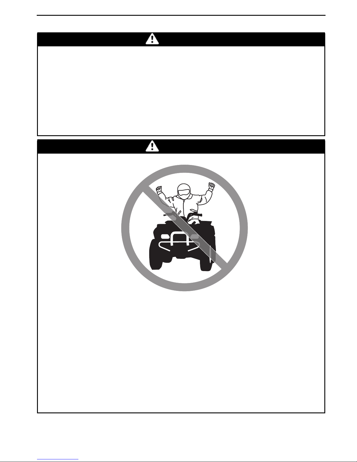
– Never carry a passenger on this vehicle.
– Never o perate this vehicle on any p aved surfaces, including sidewalks,
driveways, parking lots an d streets .
– Never operate this vehicle on any public s treet, road or hi ghway, even a
dirt or gravel one.
– Never take place on this vehicle without wearing an approved helmet
that fits proper ly. You should also wear eye protection (goggles or face
shield), gloves, b oo ts, long sleeved shirt or jacket, and long pants.
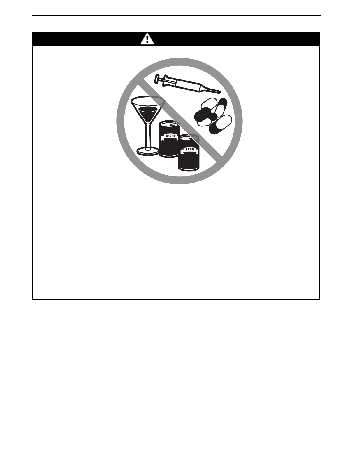
– Never ride this vehicle under the influen ce of alcoh ol or drugs. They slow
reaction time and impair judgement.
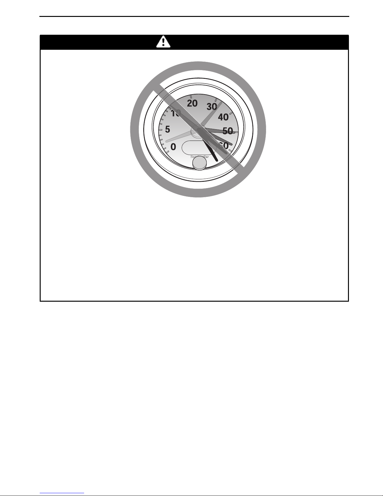
– Never operate at exc es s i ve speeds. Always go at a speed that is proper
forthe terrain, visibility, and operating conditions, and your experience.
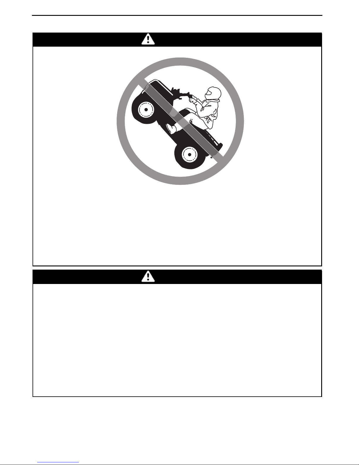
– Never attempt wheel ie s, jumps, or other stunts.
– Always inspect and confirm the safe operating condition of your vehicle
prior to ride. Always follow the inspection and maintenance procedures
and sc hedules desc ri bed in th is Operator's Guide.
– Always keep bothhands on the handlebars andboth feeton the footpegs
of the vehicle during operation.
SAFETY VIDEO
before operation.
________
SAFETY INFO RM ATION
________
9
Page 12

SPECIAL SAFETY MESSAGES
WARNING
– Using foot protectors instead offootpegs as a resting area during opera-
tion may lead to foot protector breakage. Your foot or leg may come into
contact with the rear wheels, wh ich couldinjure youorcause anaccident.
Never use foot p rotectors as a resting area.
– Always go slowl y and be extra careful when operati ng on unfamiliar ter-
rain. Always be al ert to changing terrain cond itions wh en op erating this
vehicle.
– Never operate o n excessively rough, slippery or loose terrain until you
have learned a nd practiced the skills necessary to control this vehicle on
such te rrain. Always be especially cautious on these kinds of terrain.
– Always follow proper procedures for turning as described further in this
Operator's Guide. Pr ac tice turning at low speeds before attempting to
turn at fas t er speeds. Do not turn at excessive sp eed.
– Never operate this vehicle on hills too steep for the veh icle or for yo ur
abilities. Practice on smaller hills before attempting larger hills.
– Always follow proper procedu res for climbing hills as described further
in this Operator's Guid e. Check the terrain carefully before you start up
any hill. Never climb hills wi th excessively slipp ery or loose su rfac es .
Shift your weight forward. Never open the throttle sud denly or m ak e
sudden gear changes. Never go over the top of any hill at high speed.
– Always follow proper procedures for going down hills and for braking
on hills as described further in this Operator's Guide. Check the terrain
carefully before you start down any hill. Shift your weight backward.
Never go down a hill at hi gh speed. Avoid g oi ng down a hill at an angle
that would cause the vehicle to lean sharply to one side. Go straight
down the hill where possible.
– Always follow p rop er procedures for crossi ng the side of a hill as de-
scribed fur ther in this Opera tor' s Guide. Avoid hi lls with excessively
slippery or loose surfaces. Shift your weight to the uphill side of the
vehicle. Never attem pt to turn the vehicle around on any hill u nti l you
have mastere d th e turning tec hn iq ue described in this Operator's Guide
on level ground. Avoid crossing the side of a steep hill if possible.
– Always use proper procedures if you stall or roll backwards when climb-
ing a hill. To avo id stalling, use proper gear and maintain a stead y speed
when climbing a hill. If you stall or roll backwards, follow the specia l
procedure for braking described in this Operator's Guide. Dismount
on the uphill side or to a side if pointed straight uphill. Turn the vehicle
around and remount, following the procedure described further in this
Operator's Guide.
– Always check fo r obstacles before operating in a new area. Never at-
tempt to operate over large obstacles, such as large rocks or fal len trees.
Always follow proper procedures when operating over obstacles as
described further in this Operator's Guide.
10
_______
SAFETY INFO RM ATION
________
Page 13

SPECIAL SAFETY MESSAGES
WARNING
– Always be careful when skidd ing or sliding. Learn t o safel y control skid-
ding or sliding by p rac t icing a t low speeds and on level smooth terra in.
On extremely slippery surfaces, such as ice, go slowly and be very cau-
tious in order to reduce the chance of skidding out of control.
– Never operate this vehicle in fast flowing water or in water deeper than
that sp ec ified in this Operator's Guide. R emember that wet brakes may
have reduced stop pi ng ability. Test your brakes after leaving water. If
necessary, apply them several times to let friction dry out the pads.
– Always use the size and type of tires specified further in this Operator's
Guide. Always mai ntain proper tire pressure as described further in this
Operator's Guide.
– Never modify this veh i cle th rou gh improper installation o r use of acces-
sories. Only use BRP's approved accessories.
– Never exc eed the stated load limits for this vehicle including the operator
and all other added accessories.
________
SAFETY INFORMATION
________
11
Page 14

OPERATION WARNINGS
The following warning and their format have been requested by the United States
Consumer Product Safety Commission and are required to be in the Operator's
Guide for all ATVs.
Note: Th e foll owi ng i llustrations are general representa t ions only. Your m odel
may differ.
WARNING
V00A0AQ
POTENTIAL H AZ ARD
Operating this v ehicle without proper instruction.
WHAT CAN HAPPEN
The risk of an a ccident is greatly increased if the operator does not know
how to operate this vehicle properly in different situations an d on different
types of t errain.
HOW TO AVOID THE HAZARD
Beginning and inexperienced opera tors should complete a training course.
They should then regularly practice the skills learned in the course and the
operating techniques described in this Operator's Guide.
For more informati on about the training course, contact an authorized
Can-Am dealer.
12
_______
SAFETY INFO RM ATION
________
Page 15

V00A01Q
OPERATION WARNINGS
WARNING
POTENTIAL H AZ ARD
Failure to follow the age recommendations for this vehicle.
WHAT CAN HAPPEN
A lack of respect for this age recommend ation can lead to severe injury or
death of the child.
Even though a child may be within the age group for which this vehicle is
recommended, he m ay not have the skills, abilities, or judgment needed to
operate th is vehicle safel y and may be involved in a serious accident.
HOW TO AVOID THE HAZARD
No one under 16 shou ld operate this vehicle.
________
SAFETY INFORMATION
________
13
Page 16
OPERATION WARNINGS
V00A02Q
WARNING
POTENTIAL H AZ ARD
Carrying a passenger on this vehicle.
WHAT CAN HAPPEN
Greatly reduces your ability t o balance and control this vehicle.
Could cause an accident, resulting in harm to you and/or your passenger.
HOW TO AVOID THE HAZARD
Never carry a passenger. Even with a lon g seat that provi des unrestricted
operator movement, it is not designed nor intended to ca rry passenger(s).
14
_______
SAFETY INFO RM ATION
________
Page 17
V00A03Q
OPERATION WARNINGS
WARNING
POTENTIAL H AZ ARD
Operating this vehicle on paved su rfac es .
WHAT CAN HAPPEN
The tiresaredesigned for off-road use only, not for use on pavement. Paved
surfaces may serious ly affect han dlin g and control of this ve hi cle, and may
cause the vehicle to go out of control.
HOW TO AVOID THE HAZARD
Never op erate this vehicle on any paved surfaces, including sidewalks,
driveways, parking lots an d streets .
________
SAFETY INFORMATION
________
15
Page 18
OPERATION WARNINGS
V00A04Q
WARNING
POTENTIAL H AZ ARD
Operating this vehicle on public streets, roads or h ighways.
WHAT CAN HAPPEN
You can collide with another veh icle.
HOW TO AVOID THE HAZARD
Never operate this vehicle on any publi c street, road or highway, even a dirt
or gravel one. In many states or provinces it is illegal to operate this vehicle
on public streets, roads or highways.
16
_______
SAFETY INFO RM ATION
________
Page 19

V00A06Q
OPERATION WARNINGS
WARNING
POTENTIAL H AZ ARD
Riding thisvehicle without wearing an approved helmet, eyeprotection and
protective clothing.
WHAT CAN HAPPEN
The following items concern all ATV's operator:
– Riding without an approved helmet increases the c hances of a sev ere
head injury or de ath in the event of an accident.
– Riding without eye protection can result in an accidentand increases the
chances of a severe injury in the event of an acciden t.
– Riding withou t protective clothin g increases the chances of severe injury
in the event of an ac c id ent.
HOW TO AVOID THE HAZARD
Always wear an ap pro ved helmet that fits properly. You should also wear:
– Eye protection (goggles or face shield)
– Gloves and boots
– Long sleeved shirt or jacket
–Longpants.
________
SAFETY INFORMATION
________
17
Page 20
OPERATION WARNINGS
V00A07Q
WARNING
POTENTIAL H AZ ARD
Riding this vehicle after consuming alcohol or drugs.
WHAT CAN HAPPEN
Could seriously affect your judgment.
Could cause you to reac t more slowly.
Could affect your balance and perception.
Couldresultinanaccidentordeath.
HOW TO AVOID THE HAZARD
Never consume al c ohol or drugs before or while riding this vehicle.
18
_______
SAFETY INFO RM ATION
________
Page 21
V00A08Q
OPERATION WARNINGS
WARNING
POTENTIAL H AZ ARD
Operating this vehicle a t ex ce ssive speeds.
WHAT CAN HAPPEN
Increases your chances of losing control of the vehicle, which c an result i n
an accident.
HOW TO AVOID THE HAZARD
Always travel at a s peed which is proper for the terrai n, visibility and operating c on di tions, a nd y our experience.
________
SAFETY INFORMATION
________
19
Page 22
OPERATION WARNINGS
V00A09Q
WARNING
POTENTIAL H AZ ARD
Attempting wh eelies, jumps and other stunts.
WHAT CAN HAPPEN
Increases the chance of an accident, including an overturn.
HOW TO AVOID THE HAZARD
Never attempt stunts, such as wheelies or jumps. Do not try to show off.
WARNING
POTENTIAL H AZ ARD
Failure to inspect the vehicle before operating.
Failure to properly main tain the vehicle.
WHAT CAN HAPPEN
Increases the possibility of an accident or equipment damage.
HOW TO AVOID THE HAZARD
Always inspect your vehicle every time prior to use it to make sure the veh icleisinsafeoperatingcondition.
Always follow the inspection and maintenance procedures a nd schedules
described further in this Operator's Guide.
20
_______
SAFETY INFO RM ATION
________
Page 23
OPERATION WARNINGS
WARNING
POTENTIAL H AZ ARD
Riding on frozen waterways.
WHAT CAN HAPPEN
Breaking through the ice can lead to severe injury or death.
HOW TO AVOID THE HAZARD
Never ride this vehi c le on a frozen surface before you are sure the ice is thi ck
enough and sound enough to support the vehicle and its load, as well as the
forcethatiscreatedbyamovingvehicle.
WARNING
V00A0BQ
POTENTIAL H AZ ARD
Removing hands f rom handlebar or feet from th e footrests during operation.
WHAT CAN HAPPEN
Removing even one hand or foot can reduce your ability to contr
cle or could cause you to lose your balance and fall off the vehicle. If you remove a foot from the footrests,your foot or leg may com e into contact with
the rear wheels, whi ch could injure you or ca use an accid
HOW TO AVOID THE HAZARD
Always keep both hands on the handlebar and both feet on the footrests
during vehicle operation.
________
SAFETY INFORMATION
ol the vehi-
ent.
________
21
Page 24
OPERATION WARNINGS
V00A0CQ
WARNING
POTENTIAL H AZ ARD
Failure to use extra care when operating this vehicle on unfamiliar terrain.
WHAT CAN HAPPEN
You can come upon hidden rocks, bumps, or holes, w ithout enough time to
react.
Could result in t he vehicle overturning or loss of control.
HOW TO AVOID THE HAZARD
Go slowly and be extra careful when operating on unfamiliar terrai n.
Always b e aler t to changing terrai n cond itions when operating the vehicle.
22
_______
SAFETY INFO RM ATION
________
Page 25
V00A0DQ
OPERATION WARNINGS
WARNING
POTENTIAL H AZ ARD
Failure to use extra care when operating on excessively rough, slippery or
loose terrain.
WHAT CAN HAPPEN
Could cause lossof traction or vehicle control, which could result in an accident, including an overturn.
HOW TO AVOID THE HAZARD
Do not operate on excessively rough, slippery or loose terrain until you
have learned and practiced the skills necessary to control this vehicle on
such terrain.
Always be especially cautious on these kinds of terrain.
________
SAFETY INFORMATION
________
23
Page 26

OPERATION WARNINGS
V00A0EQ
WARNING
POTENTIAL H AZ ARD
Turning improperly.
WHAT CAN HAPPEN
Vehicle could go out of control, causing a collision or overturn.
HOW TO AVOID THE HAZARD
Always followproperprocedures for turning asdescribed further in this Operator's Gu ide. Prac ti ce turning at low speeds before a tte mpti ng to turn at
faster speeds.
Do no t turn at excessive speed .
24
_______
SAFETY INFO RM ATION
________
Page 27
WARNING
OPERATION WARNINGS
V00AQQ
POTENTIAL H AZ ARD
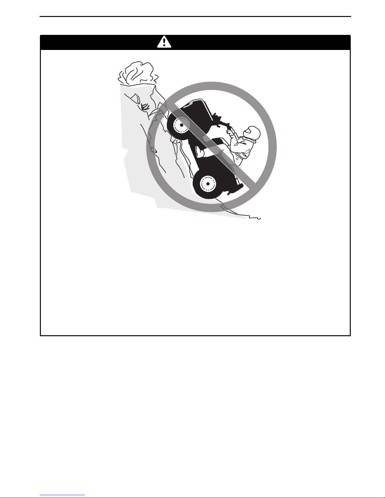
Operating on excessively steep hills.
WHAT CAN HAPPEN
The vehicle can o verturn more ea sily on extremely steep hills than on level
surfaces or smal l h ills.
HOW TO AVOID THE HAZARD
Never operate this vehicle on hills too steep for t he vehicle or for your abilities.
Practice on smaller hills before attempting larger hills.
________
SAFETY INFORMATION
________
25
Page 28
OPERATION WARNINGS
V00A0FQ
WARNING
POTENTIAL H AZ ARD
Climbing hills improperly.
WHAT CAN HAPPEN
Could cause loss of control or cause vehicle to overturn.
HOW TO AVOID THE HAZARD
Always follow proper procedures for climbing hills as described further in
this Operator's Guide.
Always check the terrain carefully before you start up any hill.
Never climb hills with excessively slippery or loose surfaces .
Shiftyourweightforward.
Never open the thro ttle su ddenly or mak e s udden g ear c hanges. The vehi-
cle could flip over b ack wards.
Never go over th e t op o f any hill at high sp eed. An obs tacle, a sharp drop, or
another vehicle or person could be on the other side of the hill.
26
_______
SAFETY INFO RM ATION
________
Page 29
V00A0GQ
OPERATION WARNINGS
WARNING
POTENTIAL H AZ ARD
Going down a hill improperly.
WHAT CAN HAPPEN
Could cause loss of control or cause vehicle to overturn.
HOW TO AVOID THE HAZARD
Always follow proper procedures for going down hills as described further
in this Operator's Guide.
NOTE: A special technique is required when braking as you go down a hill.
Always check the terrain carefully before you start down any hill.
Shift your weight backward.
Never go down a hill at high speed.
Avoid going down a hill at an angle which would cause the vehicle to lean
sharply to one side. Go straight down the hill where possible.
________
SAFETY INFORMATION
________
27
Page 30
OPERATION WARNINGS
V00A0HQ
WARNING
POTENTIAL H AZ ARD
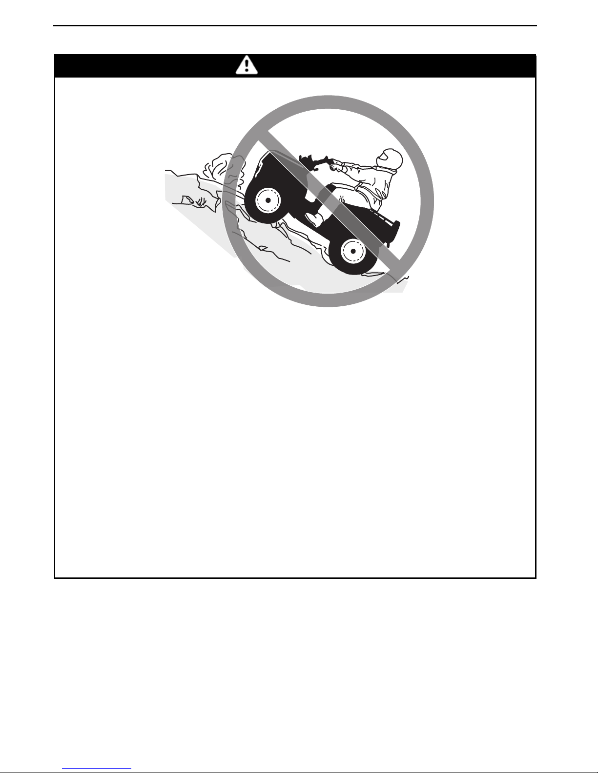
Improperly crossing hills or turning on hills.
WHAT CAN HAPPEN
Could cause loss of control or cause vehicle to overturn.
HOW TO AVOID THE HAZARD
Never attempt to turn the vehicle around on any hill untilyou have mastered
the turning technique as described further in this Opera tor's Guide on level
ground. Be very careful when turning on any hill.
Avoid crossing the side of a steep hill if possible.
When crossing the side of a hill:
Always follow proper procedures as described further in this Operator's
Guide.
Avoid hills with excessively slippery or loose surfaces.
Shift your weight to the uphill side of the vehicle.
28
_______
SAFETY INFO RM ATION
________
Page 31

OPERATION WARNINGS
WARNING
V00A0IQ
POTENTIAL H AZ ARD
Stalling, rolling backwards or improperly dismounting while climbing a hill.
WHAT CAN HAPPEN
Could result in vehicle overturning.
HOW TO AVOID THE HAZARD
Use p roper gear and maintai n st eady s peed when climbing a hill.
If you lose all fo rw ard speed:
Keep your weight uphill. Never open the throttle suddenly or make sudden
gear changes. The vehicle could flip over backwards.
Apply the brakes.
Lock parking brake after yo u have stopp ed.
Dismount on uphill side, or to a side if pointed straight uphill.
If you begin rolling backwards:
Keep your weight uphill. Never open the throttle suddenly or make sudden
gear changes. The vehicle could flip over backwards.
Never apply the rear brake whi le rolling backwards.
Apply the front brake gradually.
When fully stopped, apply rear brake as we ll and lock parkin g brake.
Dismount on uphill side, or to a side if pointed straight uphill.
Turn the vehicle around and remount, following the procedure described
further in this Operator's Guide.
________
SAFETY INFORMATION
________
29
Page 32

OPERATION WARNINGS
V00A0JQ
WARNING
POTENTIAL H AZ ARD
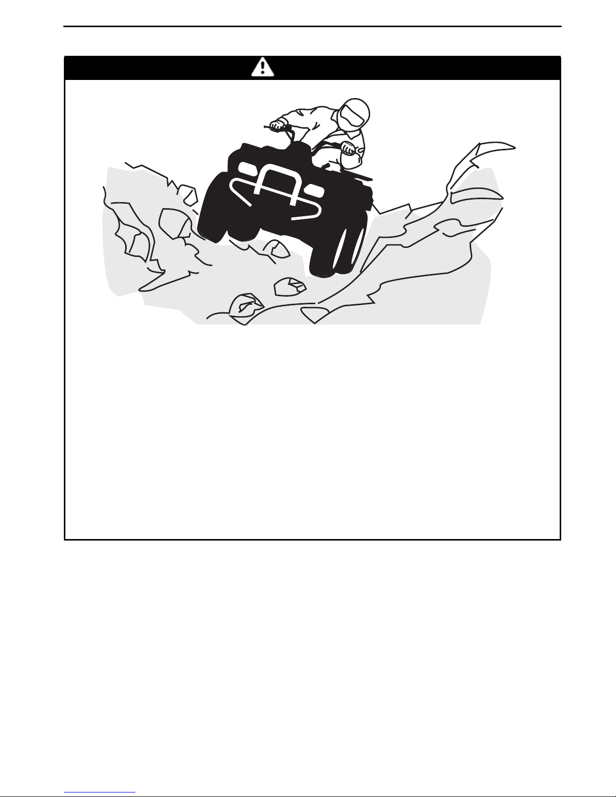
Improperly operating over obstacles.
WHAT CAN HAPPEN
Could cause loss of control or a collision.
Could cause the vehicle to overturn.
HOW TO AVOID THE HAZARD
Before operating in a new area, check for obstacles.
Never attempt to ride over large obstacles, such as large rocks or fallen
trees.
When you go over ob sta cles, always follow proper procedures a s described
further in this Operator's Guide.
30
_______
SAFETY INFO RM ATION
________
Page 33

V00A0KQ
OPERATION WARNINGS
WARNING
POTENTIAL H AZ ARD
Skidding or sliding improperly.
WHAT CAN HAPPEN
You may lose control of this vehicl e.
You may also regain traction un expectedly, which may cause the vehicle to
overturn.
HOW TO AVOID THE HAZARD
Learn to safely control skidding or sliding by p ractici ng at low speeds and
on level smooth terrai n.
On extremely slippery surfaces, such as ice, go slowly and be very cautious
in order to reduce the chance of skidding or sliding out of control.
________
SAFETY INFORMATION
________
31
Page 34

OPERATION WARNINGS
V00A0LQ
WARNING
POTENTIAL H AZ ARD
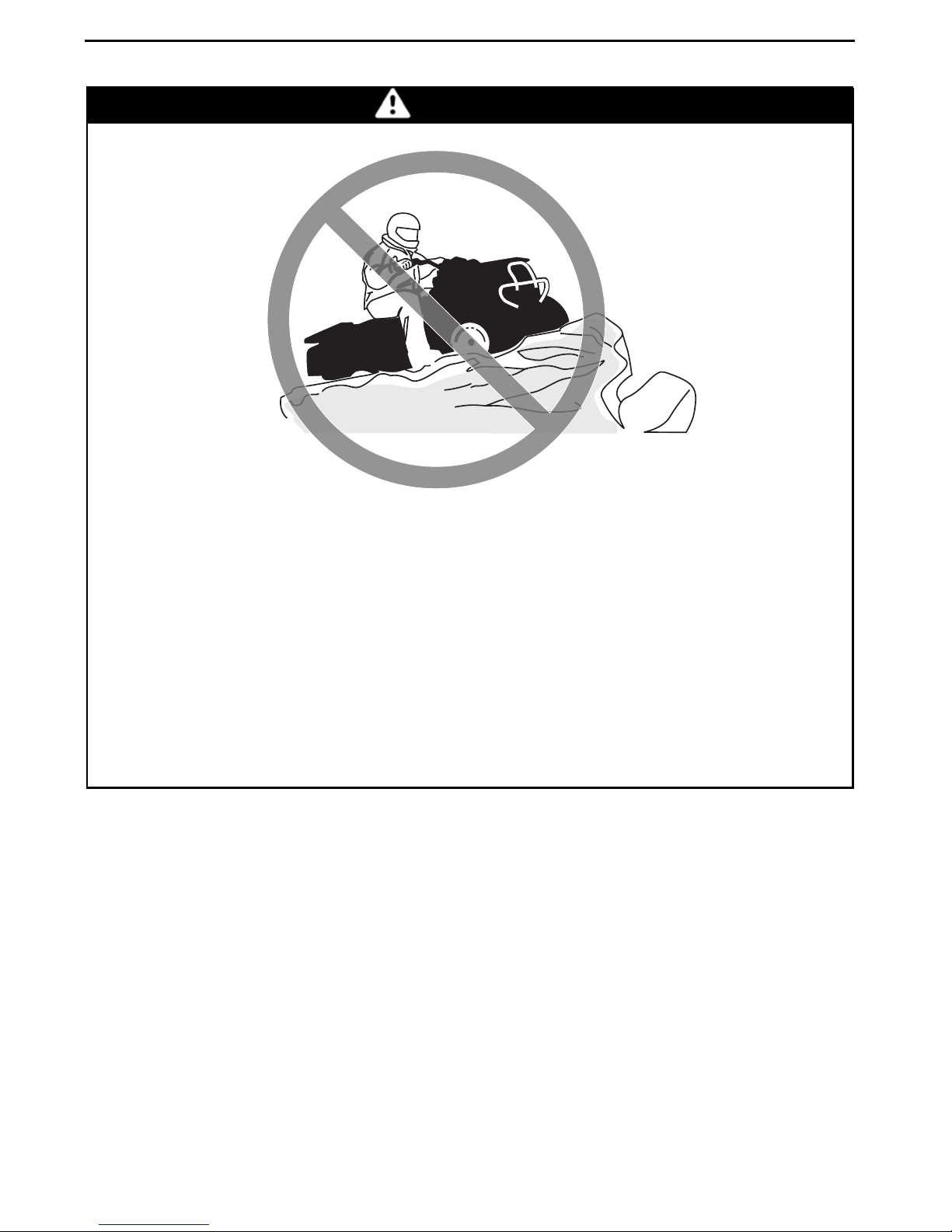
Operating this vehicle through deep or fast flowing water.
WHAT CAN HAPPEN
Tiresmay float, causinglossof traction and loss of control, which couldlead
to an accident.
HOW TO AVOID THE HAZARD
Never operate this vehicle in fast fl ow i ng water or in water deeper than that
specified further in this Operator's Guide.
Check water depth and current before you attempt to cross any water. Water should not go above footrests.
Remember that wet brake s may have reduced stopping ability. Test your
brakes after leaving water. If necessar y, apply them several times to let
friction dry out the pads.
32
_______
SAFETY INFO RM ATION
________
Page 35

V00A0OQ
OPERATION WARNINGS
WARNING
POTENTIAL H AZ ARD
Operating this vehicle with impr oper tires, or with improper or uneven tire
pressure.
WHAT CAN HAPPEN
Use of improper tires on this vehicle, or operation of this vehicle with
improper or uneve n tire pressure, may cause loss of control, tire blow outs,
tire to mov e around on its rim, and increases the risk of an accident.
HOW TO AVOID THE HAZARD
Always use the s ize and type of tires specified further in this Operator's
Guide for this vehicle.
Always maintain pro per tire pressure as described further in thisOperator's
Guide.
Always replace whee ls or tires that are dam aged.
________
SAFETY INFORMATION
________
33
Page 36

OPERATION WARNINGS
V00A0NQ
WARNING
POTENTIAL H AZ ARD
Operating this vehicle with improper modifications.
WHAT CAN HAPPEN
Improper installation of accessories or modification of this vehicle may
cause changes in handling which in some situations could lead to an accident.
HOW TO AVOID THE HAZARD
Never modi fy this vehicle th rou gh improper i nstal lation or use of accessories. All parts and accessories added to th is vehicle should be approved
by BRP and should be installed and used according to instructions. If you
have questions, consu lt an author ized Can-Am dealer.
Modification of the vehicle to increase speed and performance may violate
the terms and conditions of your vehicle's limited warranty. In addition, ce rtain modifications including the removal of engine or exhaust components
are illegal under most laws.
34
_______
SAFETY INFO RM ATION
________
Page 37

V02A02Q
OPERATION WARNINGS
WARNING
POTENTIAL H AZ ARD
Overloading t his vehicle or carrying or towing cargo improperly.
WHAT CAN HAPPEN
Could cause changes in vehicle handling which could lead to an accident.
HOW TO AVOID THE HAZARD
Never exc eed the stated load capacity for this vehicle including operato r as
well as other loads and added accessories.
Cargo should be properly distributed and secu rely attached.
Reduce speed when carrying cargo. Allow greater distance for b raking.
Always follow the instructions in this Operator's Guide for carrying cargo.
________
SAFETY INFORMATION
________
35
Page 38

OPERATION WARNINGS
V03M01Q
POTENTIAL H AZ ARD
WARNING
Transporting flammable or dangerous material can lead to explosions.
WHAT CAN HAPPEN
This can cause serious injury or death.
HOW TO AVOID THE HAZARD
Never transport flammable or dang erous materi al .
While reading this Operator’s Guide , reminder that:
Indicates a potential hazard that, if not avoided, could result in serious
injury or death.
36
_______
WARNING
SAFETY INFO RM ATION
________
Page 39

RIDIN G THE VEHICLE
To fully appreciate the pleasures and excitement of riding this vehi cle, there are
some bas ic rules and tips tha t y ou MUST follow. S om e may be new to you while
others may be comm on s ense or obvious.
Please take the time to study this Operato r's Guide an d a ll on-product warnin g labels as well as the
pletely des c ribe w ha t you should know about this vehic le before riding it.
Whether you are a new us er or an experienced rider,i t is im portan t for your personal safety that you know the controls and features of this v ehicle . Equa lly important
is k nowing how to properly ride.
Information in this O pera t or's Guide is limited. It is strongly recommende d that
you obtain further information and traini ng from your local authorities, ATV clubs
or a recogniz ed ATV training orga niz ation or contact an authorized C a n- Am dealer.
USA and Canada only: to find out about available training course nearest you,
call the Specialty Vehicle Institute of America (SVIA) at 1 800 887-2887 or in
Canada, the C a na da Sa fety Counc il (CSC ) at 1 613 739-1535 ext. 227.
The U.S. Consumer Product Safety Com m ission and a ll ATV manufacturers do not
recommended an yo ne under the a ge of 16 to ride an ATV having an engine higher
than 90 cc. Fo r the child's saf ety, we strongly recommend you also follow and enforce this recommendation. You are the sole judg e of a rider's ca pability to un derstand the risks and operate a vehicle sa fely.
SAFETY VIDEO
that cam e with this vehicle. They m ore com-
Persons with c ognitive or physical impairme nts or who are high risk take rs have an
increased exposure to overturns or collisions which may result in injury including
death.
Not all vehicles are the same. Each has its own unique performance characteristics, controls and features. Each will ride and handle differently.
Become completely fami liar with the operational control s and the genera l ope ration of the vehicle be fo re venturing into off road conditions. Practice driving in a
suitable area free of hazards and feel the response of each control. Drive at low
speeds. Higher speeds require grea ter experience , knowledge and suitable riding
conditions.
Riding co ndition s vary f rom place to place. Each is subject to weather conditions
which ma y radically change from time to time and from season to season.
Riding on sand is different than riding on snow or through forests or marshes.
Each loc ation may require a greater degr ee of awareness an d skills. Show good
judgement. A lw ays proceed with caution. Please do not take any unnecessary
risks that co uld leave y ou s trande d or possibly injured.
Never assume that the vehicle will go everywhere safely. Sudden changes in terrain caused by holes, depressions, banks, softer or har der “ground” or other irregularities may cause the vehicle to topple or become unstable. To avoid this, slow
down and always observe the terrain ahead. If the vehicle does begin to topple or
tipover, the best adv ice is t o immediately get off... AWAY from the di rection of the
tipover!
________
SAFETY INFORMATION
________
37
Page 40

RIDING THE VEHICLE
Pre-Ride Inspection
WARNING
Perform a pre-ride inspec tion before each ride to detect potential problems
during operation. The pre-ride inspection can help you monitor wear and
deterioration before they beco me a problem. Correct any problems that
you discover to reduce the risk of a breakdown or crash. See an authorized
Can-Am dealer if nec es s ary.
Before using this vehicle, the operator should always:
– Apply parking brake and check if it operates prope rly.
– Check tire press ure a nd conditio n.
– Check wheels and bearings for wear and dam a ge.
– Check location of controls and ensure they work pr operly.
– Verify if steering operates freely.
– Activate t hrottle control lever several times to ensure it operates freely. It must
return to idle position when rel eased.
– Activate the brake lever and brake pedal to make sure the brakes fully apply.
They must fully return when released .
– Ensure front brake lever position is adjusted to s uit drivers hand.
– Check all brake line fittings for tightness and against leaks.
– Whit parking brake correctly applied, ac tivate the clutch lever. It must fully re-
turn when released.
– Check d rive chain for adjustment and lubrication.
– Check sp rockets for wear and damages .
– Check tightening of rear axle faste ners .
– Check swing arm, if any lateral pl a y is detected DO NOT USE THE VEHICLE.
– Check fuel, oil and c oolant levels.
– Check for oil leaks on the engine, oil tank and transmission.
– Clean headl ights a nd ta illight.
– Ensure seat is properly latched.
– If you transport cargo, respect load capacity. Ensure cargo is properly se cu red
to the vehicle.
– Look and feel for loose parts while engine is off. Chec
– Ensure the path of travel is free of persons and o bs t
– Check operation of ignition sw itch, engine star
headlights, taillight and indicator lights.
– Start engine, remove parking brake and drive forward slowly a few feet the n ap-
ply all brak es individually to test them.
t button, engine stop switch,
k fasteners.
acles.
Correct any problem you may have found before riding. See an authorized
Can-Am dealer if necessary.
38
_______
SAFETY INFO RM ATION
________
Page 41

RIDING THE VEHIC L E
Clothing
Actual weather conditions shoul d help you decide how to dress. However, it
is important that t he operator always wear s the appropriate protective clothing
and apparel, in cluding an approved helmet, eye protection, bo ots , gloves, a long
sleeved shirt and pants. This type of clothing will prov ide you protection from
some of the minor hazards you may encounter en route. The operator must
never wear lo os e c lothi ng s uch as a scarf that ma y get entangled in the vehicle or
on tree branches and shrubs. Depending on conditions, antifogging goggles or
sunglasses may be required. Different colored l enses available for goggles or sun
glasses help you distinguish terrain variations. S ungl asses should only be worn
during the daytime.
Approved
helmet
Eye protection
Rigid chin
guard
Chest
protector
Long
sleeves
Gloves
Long, sturdy
pants
Boots
V00A0RN
________
SAFETY INFORMATION
________
39
Page 42

RIDING THE VEHICLE
Recreational Riding
Respect the rights and limitations of others. Stay a way from areas designated
for other types of off road us e. This includes snowmobile trails, eque strian tra ils,
cross country ski trails, m ountain bike trails etc. Never assume there are no other
users on the trail. Always stay to the com plete rig ht of the trail and do not zig zag
to one side of the trail then the other. Be prepared to stop or pull off to the si de if
another trail user appears in front of you.
Join a local ATV c lub. It will pro vide y ou with a map and advice or inform you where
you can ride. If a club does not exist in your area, help to start one. Group riding and
club activities provide a pleasurable, social experience.
Always keep a safe distance from other riders. Your judgment of speed, terrain conditions, weather, mec hanical condition of your vehicle and the “trust i n
judgment” you have in others around you will he lp you m a k e a better c hoice of
appropriate safe d istance. This vehicle, like any other motorized vehicle, cannot
stop “on a dime”.
Before you ride, tell someone w here y ou a re planning to travel and your exp ect ed
time of return. Never consume alcohol or drugs before or while riding!
Depending on the length of your ride, carry a dditional tools or emergency equipment. Fin d out where you can get additional g asoline and oil. Be prepared for the
possible conditions y ou may encounter. An em ergenc y first aid kit should always
be a consideration.
Enviro nment
One of the benefits of this vehicle is that it can take you off the beaten pa t h away
from m os t communities. However, you should always r es pect nature and the
rights of others to enjoy it. Do not ride in environmentally sensitive area s . Do not
drive over forest c rops or shrubs... n or cut down trees or take down fencing... nor
spin y our wheels and de stroy the terrain. “Tread Lightly”.
Chasing wildlife is in many areas illegal. Wildlife can die of exhaustion after being
chased by a motorized vehicle. If you en counter animals on the trail, s top a nd observe qui etly and with caution. It will be one of the better memories of your life.
Observe the rule... “what you take in, carry out”. Do not litter. Do not start campfires unless you have permission to do so... and then only... away from dry areas.
The hazards you may create on the trail may cause injury to others or yourself, even
at a later date.
Respect farm lands. Alw a ys obtain the perm ission of the landowner before riding
on private land. Resp ec t crops, farm animals and property lines. If you come to a
closed a gate, close it ag ain behind you.
Finally, do not pollute s tre ams, lakes or rivers and do not modify the engine or muffling system, or remove any of its comp onents.
40
_______
SAFETY INFO RM ATION
________
Page 43

RIDING THE VEHIC L E
Design Limitation
Although the v ehi cle is exceptionally rugged for its class, it is still a light vehicle by
definition a nd its operation must be restricted to its proper purpose.
The addition of weight to any part of the v ehicle changes its gravitational stability
and modifies its performance.
Off-Highway Operation
The very nature of off-highway operation is dan gerous . Any terrain, which has
not been specially prepared to carry vehicles, presents an inherent danger where
angularity, terrain substance and exact steepness are unp redicta ble. The terrain
itself presents a continual elem ent of danger, which mus t be k nowingly a ccepted
by anyone venturing over it.
An operator who takes a vehicle off-road should always exercise the utmost care in
selecting the safest path and kee ping close watch on the terrain ahead of him. On
no account shoul d the vehicle be ope rated by anyone who is not completely familiar with the driving instructions applicable to the vehicl e, nor shoul d it be operated
on steep or treacherous terrain.
Genera l O perating and Safety P recautions
Care, caution, ex perience and driving skill are the best precauti ons against the ha zards of vehicle opera t ion.
Whenever the re is the slightest doubt tha t the vehicle can safely negotiate an obstacle or a particular piece of terrain, alw a y s choose an alternate route.
In off-road operation, power a nd traction, not speed, are important. Never drive
faster than visibility and your own ability to select a safe route permit.
Constantly watch t he terrain ahead for sudden changes in slopes or obstacles,
such as rocks or stumps, that may cause loss of stability, resulting in tipover or
rollover.
Never operate the v ehicle if the controls do not function normally.
When s t opped or parked, always apply the pa rking brake. This is espec iall y impor-
tant when parking on a slope. On very steep inclines o r if the vehicle is carrying cargo, the wheels should be blocked using rocks or bricks. Remember to turn the fuel
valve to the closed position.
Uphill Driving
Due to configuration, this vehicle has excellent climbing ability, so much so that
tipover is possible before traction is lost. For e xample, its common to encounter
terrain s ituations w here the to p of the hill has eroded to a point that the hill peak
rises ve ry sharply. The vehicle can readily negotiate such a condition, ho wever,
in doing so, when t he front of the vehicle is driven to a point that the vehicle's
balance changes rearward tipover ca n oc c ur.
________
SAFETY INFORMATION
________
41
Page 44

RIDING THE VEHICLE
The same situ ation m a y apply if an embedded object causes the front of th e v ehicle to climb more than desired. If such a situation occurs take an alternate route.
Be aware of side hilling dange rs w hen doing so.
It is also wise to know the terrain condi tion on the other side of the hill or ba nk . All
too o ften there exists a sha rp drop-off that i s impo ssible to negotiate or desc end.
Downhill Driving
This vehicle can climb steeper slopes that it can descend s a f ely. Therefore, it is essential to assure that a safe route exists to descend a slope before you climb it.
Decelerating while negotiating a slippery downhill s lope could “toboggan” the vehicle. Maintain steady speed and/or accelerate slightly to regain control.
Side Hilling
Whenever possible, such operation should be avoid ed. If necessary, do so with
extreme caution. Side hilling on stee p inclin es could res ult in rollover. In add ition,
slippery or unfirm su rfaces could res ult in uncontrollable side sliding. Do not attempt to turn the vehicle downhill with the s lide . Avoid all objec ts or depressions
that will intensify the ra ising of one side of the vehicle higher than the other, thus
causing rollover.
Drop-Offs
This vehicle will “bottom-out” and usually stop if either the front or rear wheels are
driven ov er a drop-off. If the drop is sharp or deep, the vehicle will nose dive a nd
tipover.
WARNING
Avoid negotiating drop-offs. Reverse and select an alternate route.
Riding Te chniques
Riding your vehicle too fast for the conditions may result in injury. Apply o nly
enough throttle to proceed sa fely. Stat istics show that high speed turns usually
result in mishaps and injury. Always remember that this vehicle is heavy! Its pure
weight alone may entrap you should it fall and pin you down .
This vehicle is not designed for jumping nor can it, or you, absorb the energy of high
impacts such as jumping. Performing “wheeli es ” can cause the vehicle to flip over
onto you. Both practices have a high risk for you a nd s hould be avoided at all times.
To maintain proper c ontrol it is strongly advised that you keep your hands on the
handlebar and within easy reach of all co ntrols. The same holds true for your feet.
To minimize the possibility of any leg or foot injury, keep your feet on the footrests
at all times. Do not direct your toes outwards nor place your foot out to assist
turning as the y ca n be hit or s na gged by passing obsta c les or may conta c t the
wheels.
42
_______
SAFETY INFO RM ATION
________
Page 45

RIDING THE VEHIC L E
V00A0UL
Even though there is an adequate suspens ions system on this vehicle there are
“washboard” or rough terrain conditions that will m a k e you feel uncom fortable
and even c au se ba ck injury. “Posting” or riding in a crouc hed position will often
be required. Slow down and allow your flexed legs to absorb impact.
This vehicle is not designed for riding on roads or highways. In most places it is an
illegal practice. Riding your vehicle on roads or highways could cause a collision to
occur with a nother veh icle. The tires of this vehicle are not suited for paved road
use. Pa v em ent may seriously affect the handling and control of the vehicle. Ridi ng
on roads or soft s houlders may confuse other road users, especially if your l ights
are on. If you have to cross a road, the lead driver should get off his vehicle, then
observe and give directions to the other riders. The l ast person after crossing then
assists the lead driver to cross. Do not travel sidewalks. They are designated for
pedestrian use.
Water can be a unique haz a rd. If it is too deep the vehicle m ay “flo at” and topple.
Check the water dep th an d current before you attempt to cross any water. Water
should not go abov e the footrest. Be wary of slippery surfaces such as rocks,
grass, l ogs, etc., both in the water and on its banks. A loss of traction may o ccur.
Do n ot attempt to enter the water at high s peed. The water will ac t as a brake and
could t hrow you off the vehicle.
________
SAFETY INFORMATION
________
43
Page 46

RIDING THE VEHICLE
V00A0VL
Water will affect the braking ability of your vehicle. Make sure you dry the brakes
by applying them several times after the vehicle leaves the water.
Mud or m a r s h lands may be encountered near water. Be prepared for sudden
“holes” or changes in depth. Similarly so, b e watchful of haza rds such as rocks,
logs, etc., partially c ov ered by vegetation.
If your trip crosses frozen waterways, make sure that the ice i s thick enough and
sound enough to support the tota l weight of y ours elf, the vehicle an d its load. Be
ever watchful of open water... it is a sure indication that the ice thickness will vary.
If i n doubt, do not attempt to cross.
Ice w il l also affect the control of the ve hicle. Slow dow n and do not “gun” the
throttle. This will only result in spinning of the tires a nd possible tipover of the
vehicle. Avoid rapid braking. This again will possibly res ult in an uncontrolled slide
and tip ov er of the vehicle. Slush should be avoided at all tim es since it could block
the operation or controls of the vehicle.
Riding i n snow may affect the brakes stopping ability. Safely reduce speed and
allow greater distance for braking. Snow projection may cause ice build up or
snow accumulation on brake components and controls. Apply brakes frequently
to prevent ice or snow accumulation. Carefully inspect the b rake system before
each ride and always keep brake pedal, footrests, floor boards and brake levers
freeofsnowandice.
Sand and riding on sand dunes or on snow is another unique experience but
there are som e basic precautions that sh ould be observed. Wet, deep or fine
sand/snow may create a loss of traction and cause the v
or become “bogged” down. If this occurs look fo r a firmer base. Again, the best
advice is to slow down and be watchful of the conditions.
ehicle to slide, drop off
44
_______
SAFETY INFO RM ATION
________
Page 47

RIDING THE VEHIC L E
When ridi ng in s a nd dunes it is advisable to equip the vehicle with an antenna type
safety flag. This will help make your location more visible to others over the next
sand dune. Proceed carefully should you see another safety flag ahead. Since the
antenna type safety flag can s na g and rebound on your body if caught, do not use it
in ar eas where there are low hangin g branches or obstacles.
Riding on loose stones or gravel is very similar to riding on ice. They will affect
the steering of vehicle... possibly c a using it to slide and tipover especially at
high speeds. In addition, braking distance may be a affected. Remember that
“gunning” the throttle or s liding m a y cause loose stones to be ejected rea rwa rds
into the path of another rider's way. Never do it deliberately.
V00A0WL
If you do get into a slide or skid, it may help to turn the handlebar into the direction
of the skid until you regain control. Never jam the brakes and lock the wheels.
Respect and follow all posted trail signs. They are there to help you and others.
Obstacles in the “trail” should be traversed with caution. This includes loose
rocks, fallen trees, slippery surfaces, fences, posts, and e mba nk m ents and
depressions. You should a void them whenever possible. Remem ber tha t some
obstacles are too large or dangerous to c ros s and should be a v oided. Small rocks
or fallen trees may be safely crossed... approach at a 90° angle. Stand on the
footrests whi le keeping your knees f lexed. A djust speed without losing m omentum and do not “gun” the throttle. Hold handlebar firmly. Place your body weight
rearwards and proceed. Do not try to lift the vehicle front wh eels off the ground.
Be aware that the object may be slippery or may move while crossing.
When driving on hills or slopes two things are highly important... be p re pared
for slippery surfaces or terrain variations and obstacles and... use proper body
positioning.
When stopp ed or parked a lw a y s apply the pa rk ing device. Thi s is especially important when parking on a slope. On very stee p inclines or if the ATV is carring a cargo,
the wheels should be blocked using rocks or bricks.
________
SAFETY INFORMATION
________
45
Page 48

RIDING THE VEHICLE
Uphill
Keep your body weight forward towards the top of the hill. Keep your feet on the
footpegs and shift into low gear then accelerate and when necessary, change gear
quickly as y ou climb. Do not over-spe ed s ince this may ca us e the front of the vehicle to lift from the ground and fall back on you. If the hill is too steep and you c annot
proceed or the vehicle begins to roll backwards, apply the brake, being ca re ful not
to slide. Dismount then use the “U” turn or “K” turn (while walking back, n ex t to
the vehicle on the up hill side and with a hand on the brake lever, slowl y back the
rear of the vehicle toward the top of the hill then drive downhill). Always walk or
dismount on the upsi de of the s lope while keeping clear of the vehicle and its rotating wheels. Do not try to hold on to t he v ehicle if it begins to topple. Stay cle ar.
Do not ride over the cres t of the hill at high spee d. Obstac les, including sharp dropoffs, may exist.
V00A0XL
Downhill
Keep your body weight rearwards . Apply the brake gradua lly to prevent skidding.
Do not “coast” down the slope u sing s olely engine compression or in neutral gear.
46
_______
SAFETY INFO RM ATION
________
Page 49

RIDING THE VEHIC L E
V00A0YL
Side Hilling
This is one of the most risky types of riding since it may drastically change t he balance of the vehicle. It should b e avoided w herever possible. If it is necessary to do
so how ev er, it is important that you ALWAYS keep your body weight on the ups ide
of the slope... a nd be prepared to dismount on that side s hould the vehicle begin
to topple. Do not try to stop or save the vehicle from damage.
V00A0ZL
While reading this Operator’s Guide , reminder that:
Indicates a potential hazard that, if not avoided, could result in serious
injury or death.
________
WARNING
SAFETY INFORMATION
________
47
Page 50

HANG TAG
This vehicle comes with a hang tag and la bels c onta ini ng important safety info rmation.
Any person who rides this vehicle should read and understand this information before riding.
vmo2009-005-003_en
704901107
vmo2006-005-009_en
48
_______
SAFETY INFO RM ATION
________
Page 51

IMPORTANT ON P RODUCT LA BELS
The following labels are on your vehicle
and they should be considered permanent p arts of the vehicle. If missing or
damaged, they can be replaced free
of charge. See an authorized Can-Am
dealer.
Note: The following illustrations used
in this Operator's Guide are a general
representation only. Your model may
differ.
vmo2008-011-023_a
vmo2008-011-021_a
vmo2008-011-022_a
vmo2008-011-025_a
vmo2008-011-024_a
________
SAFETY INFORMATION
________
49
Page 52

IMPORTANT ON PRODUCT LABELS
vmo2009-003-004_en
LAB E L 1
NEVER USE UNDER
THE INFLUENCE OF
DRUGS OR ALCOHOL.
DRIVE CHAIN MUST BE WELL ADJUSTED AND
LUBRIC ATED. FREE PL AY IS xx mm (x/x") WITH
DRIVER ON VEHICLE. SEE OWNERS MANUAL
FOR COMPLETE INSTRUCTIONS.
vmo2008-011-088_en
LAB E L 4
V01M07Z
LAB E L 5
DRIVE CHAIN
xx mm (x/x")
V01M02Z
LAB E L 2
V02M05Y
LAB E L 3
Improper tire pressure or
overloading can cause
loss of control, resulting
in SEVERE INJURY or
DEATH.
ALWAYS maintain proper tire pressure as shown.
NEVER set tire pressure below minimum. It could cause the tire to
disloge from the rim.
NEVER exceed the vehicle load capacity of xxx kg (xxx lb)
Including weight of operator and accessories.
vmo2009-005-007_en
LOAD
UP TO
xxx kg
(xxx lb)
COLD TIRE PRESSURE
FRONT
MAX: xx.x kPa (X PSI)
MIN: xx.x kPa (X PSI)
REAR
MAX: xx.x kPa (X PSI)
MIN: xx.x kPa (X PSI)
LAB E L 6
50
_______
SAFETY INFO RM ATION
________
Page 53

(0,66,21&21752/,1)250$7,21
7+,69(+,&/(,6&(57,),('7223(5$7(21
81/($'('*$62/,1($1'0((767286(3$
$1'&$/,)251,$5(*8/$7,216)25$796,(1*,1(6
(1*,1()$0,/<
&(57,),&$7,21
67$1'$5')(/
(1*,1(',63/$&(0(17
(;+$867(0,66,21
&21752/6<67(0
5(16(,*1(0(176685/(',6326,7,)$17,32//87,21
&(9e+,&8/((67&(57,),e3285)21&7,211(5¬/(66(1&(
6$163/20%(7,/5e321'$8;1250(6'(/(3$(7
5e*/(0(17$7,216&$/,)251,(11(63285/(6977¬027(856,
6((23(5$725¶6*8,'()250$,17(1$1&(63(&,),&$7,216
92,5*8,'('8&21'8&7(853285/(663e&,),&$7,216'¶(175(7,(16
%20%$5',(55(&5($7,21$/352'8&76,1&
vmo2007-002-002
XXXXX.XXXXXX
%&;;*&
XXXXXXXXXXXXXX
JN:KU+&12[
XXXXXXXXX
FP
&$5%
XXXX
XXXX
)$0,//('(027(85
/,0,7('(6e0,66,216
'(/$)$0,//(
&</,1'5e(
6<67Ê0('(&2175Ð/(
'(6e0,66,216
XXXX
LABEL 7: NOT S HOWN
IMPORTANT ON PRODUCT LABELS
vmo2008-011-090
LAB E L 8
While reading this Operator’s Guide , reminder that:
Indicates a potential hazard that, if not avoided, could result in serious
injury or death.
________
WARNING
SAFETY INFORMATION
________
51
Page 54

IMPORTANT ON PRODUCT LABELS
52
_______
SAFETY INFO RM ATION
________
Page 55

VEHICLE
INFORMATION
_______________
53
Page 56

CONTROLS/INSTRUMENT/EQUIPMENTS
7
10
8
6
3
5
4
2
1
9
11
vmo2009-005-002_b
TYPICAL
While reading this Operator’s Guide , reminder that:
Indicates a potential hazard that, if not avoided, could result in serious
injury or death.
54
______________
12
WARNING
Page 57

1) Throttle Lever
When pushed, it i ncreases th e engine
speed that allow s the engagement of
the transmission on the selected gea r
when clutch is engaged.
When released, the engine speed
should return automaticall y to idle and
the vehicle will gradually slow down.
CONTROLS/INST R UMENT/EQUIPMENTS
vmo2008-011-002_a
1. Brake lever
2. To apply brake
Brake Lever Adjustment
The brake lever can be adjusted to suit
operator preferences. Turn adju stment c a m from position 0 to 4, position 0 being the position with the bra k e
lever farther from the handl eba r.
vmo2008-011-001_a
1. Throttle lever
2. To accelerate
3. To de celerate
WARNING
Always release the throttle when
shifting gears. Shifting gears without re leasing the throttle, could
cause loss of control including the
vehicle to overturn and m ec han ical damages.
2) Front Brake L ev er
When com press ed, the front bra k es
are applied. When released, it should
automatically return to its original position. Bra king effec t is proportional
to the force appl ied on the lever a nd to
the type and condition of the terrain.
Validate brake lever adjustment position when seated on the vehicl e by
using t he lower num ber on the adjustment cam.
vmo2008-011-003_a
1. Adjustment cam
2. Brake lever
3. Adjustment position, when seated on the
vehicle
3) Clutch L ev er
When compressed, the clutch is disengaged. When released, the clutch is
engaged.
_______________
55
Page 58

CONTROLS/INSTRUMENT/EQUIPMENTS
vmo2008-011-004_a
1. Clutch lever
2. To disengage
3. To engage
WARNING
Always release the throttle when
shifting gears. Shifting gears without re leasing the throttle, could
cause loss of control including the
vehicle to overturn and m ec han ical damages.
WARNING
Always use the parking brake
when the vehicle is not in operation.
WARNING
Make sure parking brak e is fully
disengaged before operating the
vehicle.
When you ri de the vehicl e, brakes
thatarecausedtodragbyacontinuous pressure on the lever may
cause d amage to the brake s ys tem
and cause loss of braking capacity
and/or fire.
To engage mechanism: Squeeze
front brake lever and maintain while
moving lever lock with a finger. Front
brake lever is now compressed and
applying front brakes.
4) P arking Brake
When applied, it temporarily prev ents
the vehic le from m oving. Useful when
the brake needs to be locked fo r e xample such as doing a K-turn, during transportation or wh en the vehicle is not in
operation.
vmo2008-011-005_a
1. Parking brake
vmo2008-011-005_b
Step 1: Squeeze fr ont brake lever and maintain
Step 2: Move parking brake lever to desired
position
Note: Parkingbrakecanbeadjustedin
four (4) different position s.
56
______________
Page 59

vmo2008-011-006_a
PARKING BRAKE POSITIONS
CONTROLS/INST R UMENT/EQUIPMENTS
Headlights Switch
NOTICE
Parking brake position
can vary dependi ng on brake pads
wear. Ensure when the parking
brake is applied that the vehicle
stays securely in place.
To releas e mechanism: Squeeze
front brake lever. Lever lock should
automatically return to its original position. Front brake lever should return to
rest position. Always release parking
brake before riding.
5) Multifunction Switch
The controls located o n this multifunction switch housing are:
vmo2008-011-008_a
HEADLIGHTS SWITCH F UNCTIONS
1. Headlights switch
2. Low beam
3. High beam
Note: Place igni tion swi tch to O N
“without headlig hts ” position to turn
off the headlights.
vmo2008-011-007_a
1. Headlights switch
2. Engine stop switch
3. Engine start button
vmo2008-011-027_a
IGNITION SWITCH POSITIONS
1. OFF
2. ON “with light”
3. ON “without light ”
Engine Stop Switch
This switch is used to s top the engine
and as a n emergency contro l.
To stop engine, fully release throttle
leverthenusetheenginestopswitch.
_______________
57
Page 60

CONTROLS/INSTRUMENT/EQUIPMENTS
Note: While engine can be stopped
by turning ignition key OFF, we recommend the engine be stopped by the
engine stop switch.
vmo2008-011-009_a
1. Engine stop switch
2. OFF
3. RUN
Engine Start Button
The start button is used to start the engine. When the s t art button is pushed,
the starter motor will c ra nk the engine.
Refer to
OPERATING INSTRUCTIONS
STARTING THE ENGINE
section
in
for p roper starting procedure.
vmo2008-011-027_a
IGNITION SWITCH POSITIONS
1. OFF
2. ON “with headlights”
3. ON “without hea dlights”
Insert key in switch and turn to the desired position. To remove key, turn key
to OFF pos ition then pul l it out.
Note: When selecting either ON with
headlights or ON without headlights,
the taillight will be on. On both ON positions, the lights will be on with the
engine running or not. Always turn the
ignition key to OFF position after engine has been stopped.
7) Te ther Stop Sw i tch
X xc Package O nly
vmo2008-011-009_b
1. Engine start button
6) Ignition Switch
Key-operated 3 position switch.
58
______________
When tether cord clip is removed from
switch, it shuts the engine off to prevent the ATV from running away if the
operator accidently fall s off.
To allow engine to sta r t, insta ll tether cord clip betw een knob and s witch
housing as shown.
Page 61

vmo2009-005-005_a
CONTROLS/INST R UMENT/EQUIPMENTS
8) Indicator Lamps
vmo2008-011-028_b
1. Neutral (N) indicator lamp
2. Check engine indicator lamp
3. Low fuel level indicator lamp
Transmission is in neutral position.
vmo2009-005-006
WARNING
Always operate vehicle with tether
cord eyel et attached to clothing or
wristband.
Lamp ON
to
TROUBLESHOOTING
tion or contact an authorized
Can-Am dealer.
Lamp blinks: Engine is under
a protection mode (limp home),
contact an authorized Can-Am
dealer.
Low fuel level. There is approxi mately 2.5 L (0.6 U. S. gal) of fuel
left in fuel tank.
(1)
The lamp stays ON when the ignition
switch key and engine stop switch are
in running position and the engine is not
running.
(1)
: Engine fault, refer
sec-
9) Rear Brake Pedal
When pressed down, the rear brake
is a pplied. Wh en releas ed, it should
return to its original position.
_______________
59
Page 62

CONTROLS/INSTRUMENT/EQUIPMENTS
vmo2008-011-012_a
1. Rear brake pedal
Note: Brak ing e ffect is proportion al to
the force applied on t he lever and to the
type and condition of the t erra in.
10) Gearshift Pedal
vmo2008-011-029_a
1. Tool kit
The tool k it contains tools for basic
maintenance.
12) Seat Latch
vmo2008-011-011_a
LH SIDE OF VEHICLE
1. Gearshift pedal
Refer to
SHIFTING THE TRANSMIS-
SIONinOPERATING INSTRUCTIONS
section for more details.
11) Tool Kit
The tool kit is located in the service
compartment underneath seat.
Located underneath rear end of seat.
It allows the removal of seat to give
access to air filter housing a nd serv ice
compartment.
vmo2009-023-002_c
1. Seat latch
Seat Removal
Pull latch rearward while gently lifting
rear of seat. Contin ue lifting movement until you can release seat retaining devices, then completely remov e
seat.
60
______________
Page 63

vmo2008-011-030_a
1. Seat latch
Seat Installatio n
Insert se at front upper slot into co olant
tank hook, then make sure seat middle
tab is well engaged. W hen seat res ts
in its position, firmly push seat down to
latch.
CONTROLS/INST R UMENT/EQUIPMENTS
Note: A distinctive snap w ill be felt.
Double check that the seat is secure by
giving it a tug to confirm proper latching.
vmo2008-011-031_a
1. Upper slot
2. Middle tab
WARNING
Make sure seat is securely latched
before riding.
_______________
61
Page 64

FUEL
Recommended Fuel
Use premi um unleaded gasoline, available from most service stations or o xygenated fuel containing a maximum
total of 10% of ethanol or methanol
or both. The gasoline used must have
the following recommended minimum
octane number.
OCTANE NUMBER
Inside North
America
Outside N orth
America
NOTICE
other fuels. The use of unrecommended fuel can result in vehicle performance deterioration and
damage to critical parts in the fuel
system and engine components.
Never expe riment with
(91 (RON + MON)/2)
95 RON
Fueling Procedure
NOTICE
over fuel tank cap becau s e the vent
hole on the top of fuel tank cap can
be blocked and the engine could
misfire.
Unscrew counterclockwise and remove cap to allow fuel tank filling then
fully tighten cl oc kwise.
Never place anything
vmo2008-011-106_a
1. Fuel tank cap
2. Vent tube
WARNING
Always stop engine before refueling. Open cap slowly. If a differential pressure condition is noticed (whistling sound heard when
loosening fuel tank cap) have vehicle inspected and/or repaired
before further operation. Fuel
is flammable and explosive u nder certain conditions . Never use
an open flam e to check fuel level. Never smoke or allow flame or
spark in vicinity. Always work in
a well-ventilated area. Never top
up the fuel tank before placing the
vehicle in a warm area. As temperature increases, fuel expands and
may overflow. Always wipe off
any f uel spillage from the vehic le.
Position vent tube in steering column.
While reading this Operator’s Guide , reminder that:
Indicates a potential hazard that, if not avoided, could result in serious
injury or death.
62
______________
WARNING
Page 65

OPERATING INSTRUCTIONS
Operation During Break-In
Period
Engine
A break-in period of 10 operat ing hours
is required before running the vehicle
at sustained full throttle.
During this period, maximum throttle
should not exceed 1/2 to 3/4 opening.
However, brief full acceleration and
speed variations contribute to a good
break-in. Continued wide op en throttle accelerations, prolonged cruising
speeds and engine overheating are
detrimental during the break-in period.
10-Hour Inspection
Note: Th e 10-hour inspec tion is at the
expense of the vehicle owner.
We suggest that after the first 10 hours
or 400 km (250 mi) of operation,
whichever comes first, your vehicle
be inspected by an authorized Can-A m
dealer. Refer to
FORMATION
MAINTENANCE IN-
section.
Starting the Eng ine
vmo2008-011-038_a
X xc Package
Install tether cord cli p on tether
stop switch, refer to
INSTRUMENTS/EQUIPMENT
CONTROLS/
.
All Mode ls
Shift transmission to NEUTRAL position or press and hold clutch lever.
Insert key in ignition switch and turn to
ON position.
vmo2008-011-027_b
PlaceenginestopswitchtoRUNposition.
_______________
vmo2008-011-019_c
vmo2008-011-004_b
63
Page 66

OPERATING INSTRUCTIONS
Press and hold eng ine start button until
engine starts.
vmo2008-011-038_b
Release button immediately when engine has started.
One full stroke of the pe dal shifts the
transmission to the next hi gher or lower gear in the sh ifting sequence. The
pedal should a utom a tica lly return to its
original position.
To upshift to a higher gear, put the end
of your boot under gearshift lever and
lift up the pedal one full stroke. To
downshift, lean the tip of th e gearshift
pedal and depress pedal one full
stroke.
vmo2008-011-038_c
WARNING
Do not ap ply throttle while starting.
Shifting th e Tr ans mission
Gearshi ft Control
To shift the transmission, pull in the
clutch lever, then operate gea rs hift
pedal as follows.
WARNING
Always use th e clutch lever to upshift or downshift.
vmo2008-011-019_g
WARNING
Always release the throttle when
shifting gears. Shifting gears without re leasing the throttle, could
cause loss of control or cause the
vehicle to overturn.
NOTICE
is fully disengaged before operating
vehicle.
Make sure parking brake
Stopping the Engine
WARNING
Avoid parking veh icl e on slope.
Release throttle and c om pletel y stop
the vehicle.
64
______________
Page 67

vmo2008-011-001_b
Apply the parking brake.
OPERATING INSTRUCTIONS
WARNING
Always use the clutch lever when
shifting gears.
vmo2008-011-019_d
vmo2008-011-006_a
Depress and hold clutch lever.
Set engine stop switch to OFF position.
vmo2008-011-009_c
Turn ignition key to OFF position and remove key.
vmo2008-011-004_b
Shift to 1stgear.
_______________
65
Page 68

OPERATING INSTRUCTIONS
vmo2008-011-027_c
Note: O n the X xc model, pull ing the
tether cord clip out of the tether s t op
switch will a lso stop the engi ne.
Post-O peration Care
When vehicle is used in salt-water environment, rinsing the vehicle w ith
fresh water is necessary to preserve
vehicle and its com ponents. Metallic
parts lub r ication is highly recommended. Use XP-S Lube (P/N 293 600 016)
or an equivalent. This must be performed at the e nd of ea ch operating
day.
Refer to
TION
– Inspect air filter housing drain tube
for oil accumulation, if any oil is
found, clean air filter and a ir filter
housing.
– Check engine oil level a nd refill if
necessary.
– Check en gine coolant level and r efil l
if necessary.
MAINTENANCE INFORMA-
and i ns pec t the following.
What to Do if Vehicle Is
Immersed in Wate r
Should the vehicle becom e imm ers ed,
it will be necessary to take it to an authorized Can-Am dealer as soon as possible. NEVER START THE ENGINE!
NOTICE
cle can cause serious damage if the
correct restart procedu re is not fol lowed.
Immersion of the vehi-
When vehicle is operated in muddy
conditions, rinsing the vehicle is recommended to preserve vehic le and its
components and to keep l ights clean.
Note: Never use a high pressure
washer to clean the vehicle USE LOW
PRESSURE ONLY (like a garden
hose). The high pressure can cause
electrical or mechanical damages.
What to Do if Vehicle Is
Turned Over
When vehicle is turned o ve r or stays
tilted on the side, p ut the vehicle back
on its wheels, then wait 3 to 5 minutes
before starting the engine.
66
______________
Page 69

TUNE YOUR RIDE
WARNING
Suspension, steering angle and
track width adjustment could affect vehicle handling and are interrelated. Always take time to fami liarize yourself with the vehicle's
behavior after any suspension,
steering angle or track width adjustment have been made.
Rear Track Width
Adjustment
X xc Package O nly
The rear track width can be adjusted
from 117 cm (46 in) to 127 c m (50 in)
by moving spacers inside or outside
rear wheel hubs.
To adjust, proceed as follows on both
sides:
4. Adjust track width by putting the
desired amount of spacers between rear axle flange and whee l
hub ( inner side of whee l hub). Refer t o the
ARRANGEMENT
TRACK WIDTH SPACER
table below to
properly adjust track width.
5. Apply CV joint grease (P/N 293 550
019) on drive axle splines.
6. Install wheel hub. Align a wheel
hub opening with a c otter pin hole.
1. Remove wheel, see proc edure
in the
DURES
MAINTENANCE PROCE-
section.
2. Remove and discard the cotter pin.
3. Unscrew the rear wheel hu b n ut using a 41 mm socket and a pry bar a s
shown.
vmr2008-028-020_a
1. 41 mm socket
2. Pry bar
vmr2008-028-024_a
1. Wheel hub opening
2. Cotter pin hole
7. Install the unuse d spa c ers on the
outer side of hub.
vmo2009-005-001_a
1. Spacer on inner side
2. Unused spacers on outer side
_______________
67
Page 70

TUNE YOUR RIDE
WARNING
Always install all 4 spacer s on
each axle s ide. The spacers not installed on inner side of wheel hub
mustbeinstalledonouterside.
8. Install flat was her and nut then
torque nut to 250 N•m (184 lbf•ft).
If necessary, tighten nut further until one of its groov es is a ligne d with
the cotter pin hole and hub opening.
WARNING
Never unscrew wheel hub nut to
align one of its grooves with a cotter pin h ole.
9. Install a NEW cotter pin.
Track Width Spacer Arrangement
INNER
SIDE OF
HUB
OUTER
SIDE OF
HUB
TOTAL TRACK
WIDTH
er angle is s et, a grea ter f orce is required to steer the vehi c le than with a
lower angle.
The front knuc kles caster angle is f actory preset a t 6° but it is possible to adjust it degree by degree from 4° to 8°.
The caster angle va ria tion is obtained
by moving shims in front or behind the
upper s us pension arms bearing housings.
WARNING
Adjust LH and RH caster angles to
thesamevalue.
To adjust, proceed as follows on both
sides:
1. Remove wheel, see procedure in
the
TION
2. Keeping the vehicle on jack stands,
remove the bolts retaining the upper suspension arm to the frame.
MAINTENANCE INFORMA-
section.
0
1 3 119.5 cm (47 in)
2 2 122 cm ( 48 in)
3 1 124.5 cm (49 in)
4
4
0 127 cm ( 50 in)
117 cm (46 in)
Caster Adjust ment
X xc Package O nly
The caster a ngle is the angle between
the vertical and the steering knuckle
pivot axis.
When a higher caster angle is set, the
knuckles tend more to bring the front
wheels to a straight line than with a
lower angle. Also, when a higher cast-
vmr2008-030-009_a
TYPICAL
1. Upper suspension arm
2. Upper suspension arm bolts
3. Pull the upper suspens ion arm just
enough to be able to add or remove
shims.
68
______________
Page 71

TUNE YOUR RIDE
4. Adjust the desired amount of
shims,fromsidetosideoftheupper suspens ion arm bearing hous ings, taking care to keep the total
amount of shims across each bearing housing.
Note: Always move the same amount
of shims in front or behind both of t he
upper suspension arm bearing housings. Use the following illustration and
table to place shims correctly i n all four
positions a c r os s the suspension arm
bearing housings.
Caster Adjustment Shim
Arrangement (RH)
CASTER
ANGLE
4°
5°
6°
7°
8°
SHIMS AT POSITION
1234
4
3151
22
1333
0
060
4
4
2
2
4
Suspension Adjustments
Guideline
Your vehicle handli ng and comfort depend upon suspension adjustmen ts.
Choice of suspension adjustments
vary with driver's weight, personal
preference, riding speed and field condition.
3 4
1 2
5
vmo2009-023-100_a
SHIMS POSITION RH
1. Position 1
2. Position 2
3. Position 3
4. Position 4
5. Suspension arm
5. Install the suspension arm bolts
with NEW elastic nu ts and torq ue
to 48 N•m (35 lbf•ft).
Starting from the fa c tory settings, customize eac h adjustm ent one at a time.
Front and rear adjustments are interrelated. It may be necessary to readjust
the rea r sho ck absorber after adjusting front shock abs orbers for instance.
Test run the vehicle under the same
conditions; trail, speed, driver riding
position, etc. Change one adjustment
and retest. Proceed methodically unti l
you are satisfied.
When performing the shock c om pres sion and rebound damping adjustment, proceed one position (click) at a
time between test runs .
WARNING
Adjust both springs to the same
load. Un even adjustment can
cause poor handling and loss of
stability, and/or control, and increase the risk of an ac cident.
_______________
69
Page 72

TUNE YOUR RIDE
Front Sus pension
Adjustments
Spring Preload
Shorten the spring for a firmer ride and
rough trail condition.
Lengthen the spring for a softer ride
and smooth trail condition.
vmo2008-021-004_a
1. Compression adjuster (flat screwdriver)
Tur n ing i t cl o ckw ise ( H) increases
shock damping action (stiffer).
Turning it c ounterclockwise ( S) de-
creases shock damping action (softer).
Compression Damping (High
Speed)
vmo2008-011-057_a
PRELOA D ADJU STMENT
Step 1: Loosen top locking ring
Step 2: Turn adjusting ring accordingly
Step 3: Tighten top locking ring
Lift the front of the v ehicle. Spring
length should be measured without
load on the wheels.
vmo2008-011-056_a
PRELOA D ADJU STMENT
A. Same length
X xc Package O nly
Use a 17 mm wrenc h to adjust it.
vmo2008-021-004_b
TYPICAL — X XC PACKAGE ON LY
1. High speed compression adjuster
(17 mm wrench)
Tur n ing i t cl o ckw ise ( H) increases
shock damping action (stiffer).
Turning it c ounterclockwise ( S) de-
creases shock damping action (softer).
Compression Damping
(Low Speed)
Use a flat screwdriver to adjust it.
70
______________
Rebound Damping
Use a flat screwdriver to adjust it.
Page 73

vmo2008-011-075_a
ALL MODE LS
1. Rebound adjuster (flat s crewdriver)
TUNE YOUR RIDE
vmo2008-011-079_a
A. Spring length
Tur n ing i t cl o ckw ise ( H) increases
shock damping action (stiffer).
Turning it c ounterclockwise ( S) de-
creases shock damping action (softer).
Rear Suspension
Adjustments
Spring Preload
Adjust as fol lows.
Compression Damping
Use a flat screwdriver to adjust it.
vmo2008-011-060_a
1. Compression adjuster (flat screwdriver)
Tur n ing i t cl o ckw ise ( H) increases
shock damping action (stiffer).
vmo2008-011-076_a
PRELOA D ADJU STMENT
Step 1: Loosen top locking ring
Step 2: Turn adjusting ring accordingly
Step 3: Tighten top locking ring
Lift the rear of the vehicle. Spring
length should be measured without
load on the wheels.
Turning it c ounterclockwise ( S) decreases shock damping action (softer).
Rebound Damping
Use a flat screwdriver to adjust it.
_______________
71
Page 74

TUNE YOUR RIDE
FRONT SUSPENSION FACTORY
SETTINGS
DS 450:
Spring
preload
282 mm (11.1 in)
DS 450 X xc:
269 mm (10.6 in)
vmo2008-011-077_a
1. Rebound adjuster (flat s crewdriver)
Tur n ing i t cl o ckw ise ( H) increases
shock damping action (stiffer).
Turning it c ounterclockwise ( S) de-
creases shock damping action (softer).
Front Suspension Factory
Settings
For adjustment procedures, refer
to
SUSPENSION ADJUSTMENTS
GUIDELINE
SION ADJUSTMENTS
To adj us t compression and rebound,
proceed as follows:
1. Turn adjuste r clockwise until it
stops.
2. Turn adjuster counter clockwise by
the specified amount, see table below.
and
FRONT SUSP EN-
in this section.
Compression
damping
(low speed)
Compression
damping
(high speed)
Rebound
damping
DS 450: 9 clicks
DS 450 X xc: 10 clicks
DS 450 X xc:
1/2 of a t urn
DS 450: 9 clicks
DS 450 X xc: 12 clicks
Rear Suspension Factory
Settings
For adjustment procedures, refer
to
SUSPENSION ADJUSTMENTS
GUIDELINE
ADJUSTMENTS
To adj us t compression and rebound,
proceed as follows:
1. Turn adjuste r clockwise until it
stops.
2. Turn adjuster counter clockwise by
the specified amount, see table below.
REAR SUSPENSION FACTORY
and
REAR SUSPENSION
in this section.
SETTINGS
72
______________
Spring
preload
Compression
damping
(low speed)
Compression
damping
(high speed)
Rebound
damping
All models:
262 mm (10.31 in)
DS 450: 9 clicks
DS 450 X xc: 7 clicks
DS 450 X xc:
1/2 of a t urn
DS 450: 9 clicks
DS 450 X xc: 6 clicks
Page 75

VEHICLE TRANSPORTAT ION
While reading this Operator’s Guide , reminder that:
WARNING
Indicates a potential hazard that, if not avoided, could result in serious
injury or death.
When trans porting a vehicle, secure
vehicle to trailer or pickup box with
suitable tie-downs. Using ordinary
ropes is not recommended.
WARNING
Never ti p this vehic le on end f or
transporting. We recommend that
you carry the vehicle in its normal operating position (on all 4
wheels).
vmo2008-011-039_a
TYPICAL - DS 450 (FRONT LOCATION)
V00A17Y
Remember to:
– Apply the parking brake and place
thetransmissionin1
st
gear.
– Secure the vehicl e, using the appro-
priate areas. See the following illustration.
NOTICE
Attaching vehicle at other
locations m ay damage the vehicle.
_______________
vmo2008-018-017_a
TYPICAL - DS 450 X XC (FRONT LOCAT ION)
73
Page 76

VEHIC LE TRANSPORTATION
vmo2008-011-098_a
REAR LOCATION
NOTICE
locations m ay damage the vehicle.
Attaching vehicle at other
WARNING
Do not tow this vehicle behind a
car o r other vehic le. Us e a tra iler.
74
______________
Page 77

MAINTENANCE
INFORMATION
_______________
75
Page 78

MAINTENANC E SC HED ULE
Maintenance is very important for keeping your vehicle in safe operating condition. Proper maintena nce is the owner's responsibility. Perform periodi c checks
and follow the mainte na nc e s chedule.
WARNING
Failure to properly maintain the vehicle accord ing to the maintenance
schedule and procedures can mak e it unsafe to operate.
This section includes instructions for bas ic maintena nc e procedures. If you have
the necessary mechanical skills and the required tools, you can perform these procedures. If not, see your authorized Can-Am dea ler.
Other important items in the maintenance schedule that are more difficult and require s pecial tools are best performed by your authorized Can-Am dealer.
WARNING
Turn off the engine and follow these maintenance proc edures when performing mainten ance. If yo u do not follow proper maintenance procedures
you can be injured by hot parts, moving parts, electricity, chemicals or other hazards.
WARNING
Should removal of a locking device (e.g. lock tabs, self-locking fasteners,
etc.) be required when undergoing disassembly/assembly, always replace
with a new one.
76
______________
Page 79

PERIODIC MAINTENANCE CHART
INITIAL INSPECTIO N 10 H OR 400 KM
MAINTENANCE SCHEDULE
A: ADJUST
C: CLEAN
25 H OR 1250 KM
50 H O R 2500 KM
I: INSPECT
L: LUBRICATE
R: REPLACE
100 H OR 1 YE A R OR 5000 KM
200HOR2YEARSOR10000KM
TO BE PERFORMED BY
PART/TASK LEGEND
ENGINE
Oil and filter
(1)
RCustomer
Oil reservoir strainer C Customer
Engine valves I,A I,A Dealer
Engine mounting fasteners I I Dealer
Air filter
(2)
(3)
R
Customer
Exhaust system I I Dealer
Muffler spark arrester C Customer
Engine coolant I I
Radiator cap/cooling system
pressure test
Radiator
(3)
I I Dealer
I,C I,C Customer
(4)
RCustomer
(1) Inspect oil level at every
ride. FIRST engine oil/filter
replacement must be performed
after 3 fuel tanks OR 5 hours of
riding (whichever comes first).
(2) Clean at every ride.
(3) More often under severe
use such as dusty area, sand,
snow, wet or muddy conditions.
(4) Every 50 hours,
check coolant strength.
(5) Inspect adjustment at every
ride.
Clutch (5)
Dealer/
Customer
ENGINE MANAGEMENT SYSTEM
EMS sensors I I Dealer
EMS fault codes I I Dealer
FUEL SYSTEM
Throttl e body I I,L Dealer
Throttle cable I,A I,A,L
Dealer/
Customer
Fuel lines, fuel rails,
connections, check valves
I I Dealer
and fuel tank pressure test
Fuel pump pressure I Dealer
_______________
—
—
77
Page 80

MAINTENANCE SCHEDULE
PERIODIC MAINTENANCE CHART
INITIAL INSPECTIO N 10 H OR 400 KM
A: ADJUST
C: CLEAN
25 H OR 1250 KM
50 H O R 2500 KM
I: INSPECT
L: LUBRICATE
R: REPLACE
100 H OR 1 YE A R OR 5000 KM
200HOR2YEARSOR10000KM
TO BE PERFORMED BY
PART/TASK LEGEND
ELECTRICAL SYSTEM
Spark plugs
(6)
II R Customer
Battery connections I I Customer
ECM connectors
(visual inspection without
I Dealer
disconnecting)
Electrical connections
and fastening
(ignit ion system, starting
I I Dealer
system, fuel injectors etc.)
(6) Apply heat-sink paste P12
(P/N 420 897 186) on spark plugs
threads before installation.
Enginestopswitch I I Customer
Lighting system
(headlight, taillight, turn
I I Customer
signals, etc.)
DRIVE SYSTEM
Drive chain and slider (7) Customer
(8)
(3)
IIRCustomer
I I Customer
Drive chain Sprockets
Drive chain tensioner
Rear axle bearings I I Customer
Rear axle and rear axle nut
(8)
I I Customer
WHEELS/TIRES
Wheel nuts/studs I I Customer
Front wheel bearings I I Customer
Rear wheel hub L Dealer
(3) More often under severe
use such as dusty area, sand,
snow, wet or muddy conditions.
(7) Inspect, adjust and
lubricate at every ride.
(8) Check tightness.
(9) Check tire pressure and wear at
every ride.
Tires (9) Customer
78
______________
Page 81

PERIODIC MAINTENANCE CHART
INITIAL INSPECTIO N 10 H OR 400 KM
MAINTENANCE SCHEDULE
A: ADJUST
C: CLEAN
25 H OR 1250 KM
50 H O R 2500 KM
I: INSPECT
L: LUBRICATE
R: REPLACE
100 H OR 1 YE A R OR 5000 KM
200HOR2YEARSOR10000KM
TO BE PERFORMED BY
PART/TASK LEGEND
STEERING SYSTEM
Handlebar fasteners I I Dealer
Steering column and
bearing
(3)
I I Dealer
Tie rod ends I I Customer
Front wheel alignment I,A I,A Dealer
REAR SUSPENSION
Swing arm I I L Dealer
Suspension linkage I,L I,L
Customer/
dealer
(3) More often under severe use
such dusty as area, sand, snow,
wet or muddy conditions.
—
Shock absorber I Customer
Shock absorber lower pivot L Dealer
FRONT SUSPENSION
Suspension arms I I,L Customer
Ball joint boots I I Customer
Ball joints
(3)
I I Dealer
Shock absorbers I Customer
BRAKES
Brake fluid I I R
Brake pads
(9)
I Dealer
(10)
Customer
Brake discs I Customer
Brake hoses I Customer
Brake line fittings (11) Customer
(3) More often under severe use
such dusty as area, sand, snow,
wet or muddy conditions.
(10) Brake fluid replacement
or any brake system repairs
must be performed by an
authorized Can-Am dealer.
(11)Inspectateveryride.
_______________
79
Page 82

MAINTENANCE SCHEDULE
PERIODIC MAINTENANCE CHART
INITIAL INSPECTIO N 10 H OR 400 KM
A: ADJUST
C: CLEAN
I: INSPECT
L: LUBRICATE
R: REPLACE
PART/TASK LEGEND
CHASSIS
Chassis I Dealer
Chassis fasteners I I Customer
25 H OR 1250 KM
50 H O R 2500 KM
100 H OR 1 YE A R OR 5000 KM
200HOR2YEARSOR10000KM
TO BE PERFORMED BY
—
80
______________
Page 83

MAINTENANCE SCHEDULE
5-Hour Engi ne Oil and Fil ter Replacement
The Can-Am DS 450/DS 450 X xc is the most adv a nc ed sport ATV and it ha s been
designed us ing the latest technology all the way down to its synthetic multi-layer
oil filter and break-in oil. To maintain the DS 450/DS 450 X xc at the highest level of
performance, change the engine break-in oil and filter after us ing 3 fuel tanks or 5
hours of riding (which ever comes first). Contact an authorized Can-Am dealer
for more details.
10-Hour I ns pection
We suggest that after the first 10 hours or 40 0 km (250 m i) of ope ration, whichev er comes first, y our vehicle be inspec ted by an authorized Can-Am dealer. This inspection is very important and must not be neglected.
Note: Th e 10-ho ur inspe ction is at the expense of t he v ehicle owner.
We recommend that this inspection be signed by an a uthoriz ed Can-Am dealer.
Date of 10-hour inspection Authorized dealer signature
Dealer name
While reading this Operator’s Guide , reminder that:
Indicates a potential hazard that, if not avoided, could result in serious
injury or death.
WARNING
_______________
81
Page 84

MAINTENANCE PROCEDURES
Engine O il
Engine Oil Level
The en gine oil t a nk is loc a te d in front of
engine.
NOTICE
Check level fr equ entl y
and refill if necessary. Do not o verfill. Operating the engine with an
improper level may s everely damage en gi ne/transmission. W ipe off
any spillage.
Note: While checking the oil l evel, vi-
sually inspect oil tank and e ngine area
for leaks.
vmo2008-011-017_a
1. Full
2. Add
3. Operating range
To add oil, remov e the dipstick. Place a
funnel into the oil tank fill hole to avoid
spillage.
Add a sm a ll amount of oil and recheck
oil level.
Repeat the operation until oil le ve l
reaches the dipstick’s upper m a rk. Do
not overfill.
Properly tighten dipstick.
Recommended Oil
Note: Th e s a me o il lubricates both engine a nd trans m iss ion.
Use only XP -S 5W 40 synthetic oil
(P/N 293 600 039). This is a special
synthetic oil formul ated for wet clutch
type gear box.
vmo2008-011-014_a
LH SIDE OF VEHICLE
1. Oil tank dipstick
With vehicle on a level surface, start
engine and let it running at idle, arou nd
1 minute, then s top engine. Check oil
level as follows:
1. Unscrew dipstick and wipe c lean.
2. Screw dipstick until it bottoms.
3. Remove dipstick and check oil lev-
el. I t should be nea r or equal to the
upper mark.
NOTICE
The XP-S 5W 40 synthetic oil is specially formulated and
tested for the severe requirements
of this engine. Do not use other
synthetic oil, synthetic blend oil
or oil additives in Can-Am ATV wet
clutch equipped vehic les. There is
no known equivalent on the market for the mome nt. If a high quality
equivalent were available, it could
be used.
Oil Change and Oil Filter
Replacement
Oil and fil te r are to be replaced at the
same time. Oil change s hould be done
with a w a rm engine.
82
______________
Page 85

CAUTION The engine oil can
be very hot. Wait until engine oil is
warm.
Oil Drainag e
MAINTENANCE PROCEDURES
vmo2008-011-014_a
1. Engine oil tank cap
vmo2008-011-040_a
LH SIDE OF VEHICLE
1. Oil filter
vmo2008-011-105_a
1. Oil tank drain plug
2. Engine drain plug
Ensure vehicle is on a level surface.
Remove oil tank cap.
vmo2008-011-105_a
1. Oil tank drain plug
2. Engine drain plug
Clean drain plugs area.
Place a drain pan under the oil tank
drainplugarea.
Remove drain p lug and drain all oil from
oil tank.
Place a drain pan under the engine
drainplugarea.
Remove drain p lug and drain all oil from
engine.
Wipe off a ny oil spillage on frame.
Note: Allow enough time for oil to flow
out of oil filter.
Oil Tank Strainer Cleaning
Note: Refer to
SCHEDULE
for oil tank s trainer clean-
MAINTENANCE
ing frequency.
_______________
83
Page 86

MAINTENANCE PROCEDURES
Remove bolts retaining oil tank o utlet
fitting.
vmo2008-011-066_a
LH SIDE OF VEHICLE
1. Retaining bolts
2. Ta nk outl et fitting
3. Oil tank
Discard O-ring.
Remove oil t ank s trainer behind outlet
fitting.
Carefully reinstall all previously removed parts.
NOTICE
Take care not to damage
O-ring while inserting outlet fitting
into oil tank. Apply oil on O-ring to
ease installation.
vmo2008-011-100_a
OIL OUTLET ASSEMBLY
1. Hexagonal bolt
2. Washer
3. Insert
4. Outlet fitting
5. O-ring
6. Strainer
vmo2008-011-099
STRAINER
To clean oi l stra iner, use a solvent then
dry with com pres s ed a ir.
WARNING
Always wear eye protection.
Chemicals can cause a rash break
out and an injury to your eyes.
Wipe off a ny oil spillage on oil tank.
Install a NEW O-ring on the oil tank out-
let fitting.
Install t he oil tank outlet fitting on the
oil tank.
Oil Filter Replacement
Unscrew oil filter cover.
Note: Remember screws location.
vmo2008-011-042_a
LH SIDE OF ENGINE
1. Oil filter cover
2. Screw (M6 x 25)
3. Screw (M6 x 55)
84
______________
Page 87

MAINTENANCE PROCEDURES
Remove the oil filter and replace by a
new one.
Note: Check a nd ch an ge the O-ring, if
necessary.
vmo2008-011-084_a
LH SIDE OF ENGINE
1. Oil filter cover
2. Oil filter
3. O-ring
Engine Coolant
Engine Coolant Level
WARNING
Check coolant level with engine
cold. Never ad d coolant in cool ing
system when engine is hot.
Note: Whil e checking the coolant lev-
el, visually inspect engine area for
leaks.
The engine coolant t an k c ap is located underneath access cover near fue l
tank cap.
Wipe off a ny oil spillage on engine.
Change gasket on drain plugs. Clean
gasket area on engine, oil tank and
drain plugs then reinsta ll plugs.
Refilloiltankwith1.8L(1.9U.S.
quarts) of the recommended oil. Refer
to
RECOMMENDED ENG INE OIL
in
this section for more details.
Start engine and let idle for a few min-
utes.
Ensure there are no leaks.
Stop engine and check oil leve l. Refill if
necessary.
Dispose oil as p er your local environ-
mental regulations.
vmo2008-011-061_a
UNDERNEATH ACCESS C OVER
1. Coolant tank cap location
vmo2008-011-034
COOLANT TANK CAP
_______________
85
Page 88

MAINTENANCE PROCEDURES
To remove access cover, proceed as
follows.
Remove seat.
vmo2009-023-002_c
1. Seat latch
Remove fuel tank cap.
Gently pull cover rearward to remove.
vmo2008-011-033_b
Remove filler cap.
With vehicle on a level surface, liquid
is at a proper level when seen through
reservoir cap hole.
vmo2008-011-028_c
Release cover tabs from fascia.
vmo2008-011-033_a
1. Tabs
86
______________
vmo2008-011-087_a
COOLANT RESERVOIR
1. Coolant here
Fluid level can also be validated using
reservoir level marks (small ribs).
Page 89

MAINTENANCE PROCEDURES
Engine Coolant Replacement
WARNING
In order to avoid potential burns,
do not remove the coolant tank cap
or loosen the engine drain plug if
theengineishot.
vmo2008-011-107_a
COOLANT RESERVOIR
1. Level marks
Note: Cool an t may be slightly lower
when checking lev el at t em pera t ure
lower than 20°C (68°F).
Add coolant if necessary. Use a funne l
to avoid spillage. Do not overfill.
WARNING
In order to avoid potential burns,
do not remove the coolant tank cap
iftheengineishot.
Properly reinstall and tighten filler cap.
Properly reinstall all removed parts in
reverse order of their removal.
Note: A cooling system th at frequent-
ly requires coolant is the indication of
leaks or engine problem s . See an authorized Can-Am dealer.
Remove access cover, refer to
GINE COOLANT LEVEL
in this section.
EN-
Turn the coolant tank cap counterclo ckwise and remove it.
vmo2008-011-032_a
UNDERNEATH ACCESS C OVER
1. Coolant tank cap
Unscrew the drain plug slowly and
drain the coolant into a suitable container.
Note: It i s not necessary to remove
drain plug.
Recommended Engine Coolant
Always use ethy lene-glyc ol antifreeze
containing corros ion inhibitors specifically for in t ernal combustion aluminum
engines.
Cooling system must be filled with
BRP premixed coolant (P/N 219 700
362) or with distilled water and antifreeze solution (50% water, 50% a ntifreeze).
_______________
87
Page 90

MAINTENANCE PROCEDURES
vmo2008-011-042_b
LH SIDE OF ENGINE
1. Coolant drain plug
Drain com pletely and retighten the
drain plug.
Run engine at idle with the coolant tank
cap off. S low ly a dd a ddition al co olant if
necessary. Do not overfill.
With vehicle on a level surface, liquid
is at a proper level when seen through
reservoir cap hole.
Loosen gear clamp from radiator o utlet
hose.
Remove outlet ho se from radiator to
drain the system completely.
vmo2008-011-086_a
1. Gear clamp
2. Outlet hose
3. Radiator
vmo2008-011-087_a
COOLANT RESERVOIR
1. Coolant here
Liquid can also be validated using
reservoir level marks (small ribs).
vmo2008-011-107_a
COOLANT RESERVOIR
1. Level marks
Reinstall hos e and secure with gear
clamp.
Wipe off any coolant spillage on frame
and engine.
Refill coolant tank with 1.8 L (1.9 U.S.
quarts) of recom m ended coolant. Refer to
SPECIFICATIONS
tails.
88
______________
for more de-
At this poi nt, wait until engine reac hes
normal opera ting temperature. Depress the throttle lever tw o or three
times; then add coo lant if necessary.
Install coolant tank cap. Inspec t all connections for leaks.
Properly reinsta ll all previously removed parts.
Page 91

Air Filter
Air Filter Removal
MAINTENANCE PROCEDURES
NOTICE
Never remove or modify
any component in the air filter housing. Always use genuine parts or
suitable equivalents when repla cing
air filter. The engine is calibrated to
operate sp ecifically with these components. Otherwise, engine performance degradation or damage can
occur.
Remove seat.
Release clamps and remove air filter
housing cover.
vmo2008-011-043_a
1. Clamp
AirFilterCleaning
Pour air filter cleaner (P/N 219 700 341)
or an equivalent into a bucket. Put the
filter in to soak.
While filter soaks, clean inside o f air filter housing.
Rinse air filter with warm water.
Squeeze foa m to remove ex c es s wa-
ter. Let dry a ir filter thoroughly.
vmo2008-011-016_b
1. Clamps
2. Air filter housing cover
Loosen clamp and remove filter.
Note: Sligh t dust may be clea ned using a low-pressure airgun. Blow compressed air backward of operating air
flow.
If air f ilter element is da m a ged, replace
with a new one.
When the filter is dried, re-oil with air filter oil (P/N 219 700 340) or an equivalent.
Air Filter Install a tion
Properly reinstall removed parts in the
reverse order of their removal.
Air FilterHousing
Air Filter Housing Inspection
Periodically inspect air filter hous ing
drain tube for liquid or depos its.
_______________
89
Page 92

MAINTENANCE PROCEDURES
vmo2008-011-020_a
1. Air filter housing
2. Drain tube
3. Clamp
Note: If vehicle is used in dusty areas,
inspect more frequently than specified
in
MAINTENANCE SCHEDULE
.
WARNING
Never perform this operation immediately after the engine has
been running because exhaust
system is very hot.
Remove the spark arrester from the
muffler.
If liquid or depos its are found, squeeze
and remov e the clamp. P ull drain tube
out then empty it.
NOTICE
Do not start engine when
liquid or deposits are found in the
drain tube.
When liquid or deposits are found,
the air filter must be inspected/dried/
replaced depending on its condition.
Remove air filter as explained in this
section.
Muffler Spark Arres ter
Muffler Spark Arrester Cleaning
The muffler spark arrester must be
periodically cleaned from accumulated c a r bon. Refer to
SCHEDULE
.
The entire exhaust system s hould also
be visually inspected for cracks, leaks
or any damage.
MAINTENANCE
vmo2008-011-067_a
REMOVE
1. Screws
vmo2008-011-068_a
REMOVE
1. Spark arrester
Remove carbon deposits from the
spark a rres ter using a brush.
Note: Use a soft brush a nd be careful
to avoid damaging spark arrester.
90
______________
Page 93

MAINTENANCE PROCEDURES
CAUTION Never clean radiator
with your hands when it is hot. Let
the rad iator cool down before cleaning.
vmo2008-011-069_a
CLEAN
1. Clean this portion
For installation, reverse the removal
procedure.
Radiator
Radiator Clean in g
Inspect ra diating fins. They must be
clean, free of mud, dirt, leaves a nd any
other deposit that would prevent the
radiator to cool properly.
NOTICE
Be careful not to d amage
the r adiator fins when cleaning. Do
not use any object/tool that could
damage the fins. The fins are purposely thin parts to allow efficient
cooling. WHEN HOSING, USE LOW
PRESSURE ONLY, DO NOT USE A
HIGH PRESSURE WASHER.
Radiator In spection
Inspect radiator and hoses for leaks or
any damage.
See an authoriz ed Can-Am dealer to
check the performance of the cooling
system.
Gearshift Pedal
Gearshift Pedal Adjustment
Unfasten socket screw near selector
shaft end then rem ove gearshift pedal.
vmo2008-011-070_a
1. Radiator
Remove as much deposits as you can
with your hands. If water is available in
proximity, try rinsing the radi ating fins.
If availab le, use a ga rden hos e to rinse
the radiator fins.
vmo2008-011-019_b
1. Socket screw
Install gearshift pedal at your conv enience then torque socket s c r ew.
_______________
91
Page 94

MAINTENANCE PROCEDURES
Clutch
Clutch Adjustment
Note: DS 450 X xc model is equipped
with a quick cable adjuster that as no
lock nut. Adjust clutch cable as explained below but ignore the information conc erning the lock nut.
The clutch lever nomi na l free play is 10
to 15 mm (3/8 to 5/ 8 in), refer to next
photo.
vmo2008-011-063_a
1. Lock nut
Turn cable adjuster until proper dimension is obtained.
vmo2008-011-063_c
CLUTCH LEVER — NOMINAL FREE PLAY
A. 10 to 15 mm (3/8 to 5/8 in)
If the re is too much free play (more
than 15 mm (5/8 i n), adjustment can
be performed at the handlebar usi ng
clutch l ever cable adjuster. Refer to
ADJUSTMENT AT CLUTCH LEVER
be-
low.
If free play is lost, then clutch release
cover screw must be adjusted for
enough free play. Refer to
MENT AT CLUTCH COVER
ADJUST-
further.
Perform adjustments accordingly.
NOTICE
If recommended adjustments are unattainable, contact an
authorized Can-Am Dealer.
Adjustment at Clutch Lever
Loosen cable adjuster lock nut.
vmo2008-011-063_b
1. Cable adjuster
vmo2008-011-063_c
CLUTCH LEVER — PRO PER ADJU STMENT
A. 10 to 15 mm (3/8 to 5/8 in)
Tighten cable adjuster lock nut when
proper adjustment is obtained.
Adjustment at C lutch Cover
NOTICE
When ad ju s tment of the
clutch r elease cover screw is needed, it mea ns that the cl utch plates
have worn. Therefore, it is strongly recommended to take the vehicle
to an authorized Can-Am dealer for
clutch plates i nspection.
92
______________
Page 95

Loosen cable adjuster lock nut.
Loosen clutch cable adjuster to provide
maximum free play.
vmo2008-011-064_b
TYPICAL
1. Cable adjuster
Remove clutch cover access plug.
MAINTENANCE PROCEDURES
529035081
CLUTCH ADJUS TME N T WRENCH
vmo2008-011-071_a
1. Lock nut
vmo2008-011-042_c
LH SIDE OF ENGINE
1. Access plug
Install clutch adjustment wrench
(P/N 529 036 076) prov ided in tool k it
onto lock nut.
Hold adjustment screw using a flat
screwdriver, then loosen lock nut
counterclockwise.
vmo2008-011-085_a
1. Screwdriver
2. Clutch adjustment wrench
By using the screwdriver, gently turn
clutch adjuster screw clockwise to locate the point of contact w ith release
bearing, then turn screw out (counterclockwise) 3/8 to 1/2 turn from contact
point.
_______________
93
Page 96

MAINTENANCE PROCEDURES
Hold adjustment screw using the flat
screwdriver, then tighten lock nut
clockwise using the clutch adjustment
wrench.
vmo2008-011-085_b
1. Screwdriver
2. Clutch adjustment wrench
vmo2008-011-042_c
1. Access plug
Properly adjust clutch lever. Refer to
ADJUSTMENT AT CLUTCH LEVER
above.
To confirm proper adjustment, gently
push on ad justm ent screw using a finger. A small play should be felt, if not,
perform adjustment again.
NOTICE
A premature clutch disk
wear may occur i f adjustment is t oo
tight.
vmo2008-011-071_b
1. Adjustment screw
Throttle Cable
Throt t le Cable Lubrication
The throttle cable must be lubricated
with cable lubricant (P/N 293 600 041)
or an equivalent.
WARNING
Always use a silicone-based lubricant. Using another lubricant
(like water-ba sed lubricant) could
cause the throttle lever/cable to
become sticky or stiff.
Remove the throttle lever housing cover.
Reinstall access plug.
NOTICE
94
______________
Do not overtorque.
Page 97

MAINTENANCE PROCEDURES
vmo2008-011-001_d
1. Remove screws
Remove cable from throttle lev er.
vmo2008-011-108_a
Remove the throttle body side cover.
vmo2008-011-101_a
LH SIDE OF ENGINE
1. Remove screw
2. Cover
3. Throttle body
Install the c a ble luber tool (P/N 529 035
738) or an equivalent on the cable.
V00I03Y
TYPICAL
Insert the needle of the spray can in the
cable luber hole.
_______________
95
Page 98

MAINTENANCE PROCEDURES
WARNING
Always wear eye protec tion and
gloves when you lubricate a c able.
Note: Place a rag around the cable lu-
ber to prevent the lubricant to spl ash.
Put the lubricant u ntil it passes through
the cable.
vmo2008-011-072_a
1. Rubber protector
Loosen lock nut the n turn the adjuster
to obtain correctthrottle lever free play.
vmo2008-011-102_a
1. Look for lubricant here
Reinstall the cable.
Spray a little quantity of lubricant on the
throttle lever mechanism then close
the housing.
Adjust the throttle lever.
Throttle Lever
Throttle Lever Adjustment
Slide rubber protector back to expose
throttle cable adjuster.
vmo2008-011-073_a
1. Lock nut
2. Adjuster
Note: M easure throttle free play at the
tip of throttle lever.
Tighten lock nut and reinstall protector.
96
______________
Page 99

vmo2008-011-001_c
1. Throttle lever
A. 2to4mm(5/64to5/32in)
Spark Plugs
MAINTENANCE PROCEDURES
vmo2008-011-083_a
1. Spark plugs
Spark Plugs Installation
Prior to installation, make sure that
contact surfaces of cylinder head and
spark plugs are free of grime.
Spark Plugs Removal
Unplug spark plug cables.
vmo2008-011-082_a
CABLES LOCATION
Clean spark plugs and cylinde r head
with pressurized air if possible.
WARNING
Using a feeler gauge, set spark plugs
gap between 0.7 to 0. 8 mm (0.028 to
0.032 in).
Apply hea t-sink paste P12 ( P/N 420
897 1 86) on spark p lugs threads to prevent a possible seizure and to increase
heat transfer from spark plugs to cylinder head.
Screw spark plugs into cylinder head
by hand and tighten using a torque
wrench a nd a proper socket.
Torque spark plugs to 19 N•m
(168 lbf•in).
Battery
WARNING
Never charge a ba tte ry while installed in vehicle.
Always wear safety goggles w hen
using pressurized air.
Unscrew and remove spark plugs.
Battery Removal
Remove seat.
Disconnect B LA CK (–) c able first then
RED (+) cable.
_______________
97
Page 100

MAINTENANCE PROCEDURES
WARNING
Always res pect this order for disassembly; disconnect BLACK (–)
cable first.
Remove bolts retaining battery holder
and rack.
vmo2008-011-044_a
1. RED (+)
2. BL ACK (–)
3. Battery holder
Battery Cleaning
NOTICE
Do no t use a higher rated
fuse as this can cause severe damage.
To remove fus e from holder, pull fus e
out. Check if filament is melted.
1
2
A15E0KY
TYPICAL
1. Fuse
2. Check if m elted
Clean battery post and cable ends with
awirebrush.
Battery Installation
Reinstall battery i n vehicle. Fasten battery holder.
WARNING
ConnectRED(+)cablefirstthen
BLACK (–) cable. Always connect
RED (+) cable first.
Apply d ielectric grease (P/N 293 550
004) or a n equivalent on post to protect
against oxidation.
Fuses
Fuse Inspection
The electrical system is protected with
fuses. I f a fus e is damaged, replace it
by one of the sa me rating.
Fuse Location
The fuse holders a re located un derneath the seat and on the LH side of
the engine.
Fuses Under Seat
vmo2008-011-029_b
FUSES LO CATION
1. Fuse holder
98
______________
 Loading...