

Can-Am DS 450 2008, DS 450 X 2008 Shop Manual

2008
Shop Manual
DS 450™
DS 450™ X

Legal deposit:
National Library of Quebec
National Library of Canada 2007
All rights reserved. No parts of this manual may be reproduced in any form without the prior written
permission of Bombardier Recreational Products Inc. (BRP)
©
Bombardier Recreational Products Inc. (BRP) 2007
Printed in Canada
Technical Publications
Bombardier Recreational Products Inc. (BRP)
Valcourt (Quebec) Canada
®
™ Trademarks of Bombardier Recreational Products Inc. (BRP) or its affiliates.
* Trademarks of Bombardier Inc., used under license.
Can-Am™ Rotax
®
DS 450™ XP-S™
This document contains the trademarks of the following companies:
Loctite
Molykote
®
is a trademark of Loctite Corporation
®
is a trademark of Dow Corning Corporation
Snap-on®is a trademark of Snap-on Tools Corporation

TABLE OF CONTENTS
SAFETY NOTICE.................................................................................. VIII
INTRODUCTION ................................................................................... IX
GENERALINFORMATION......................................................................................... IX
VEHICLEINFORMATION .......................................................................................... IX
ENGINE EMISSIONS INFORMATION............................................................................ X
SELF-LOCKING FASTENERS PROCEDURE ..................................................................... X
LOCTITE
TIGHTENING TORQUES ......................................................................................... XIV
MANUAL INFORMATION ........................................................................................ XV
01 MAINTENANCE
01 – MAINTENANCE CHART....................................................................................... 1
02 – PRESEASON PREPARATION................................................................................. 5
03 – STORAGE PROCEDURE....................................................................................... 7
04 – SPECIAL PROCEDURES....................................................................................... 9
®
APPLICATIONPROCEDURE .......................................................................... X
FUEL SYSTEM.... .. .... ..... ..... .... .... .. .... . ... . .... .. .... . ... .. .. ... . .... .. .. ... .. ..... .... .... .. .. ... . .... .. .... 7
ENGINE................................................................................................................ 7
ELECTRICAL SYSTEM. .... .... .. .... . ... .. ..... ... . .... .. .... .... .. .. ... .. .. ... . .... .. .... .... .. .. ... .. ..... ... . .... . 7
COOLING SYSTEM .... ..... .... .... .. .... .... .. .... .... .. .... .... .. .... ..... .... . ... .. .... . ... .. .. ... .. .... . ... .. .... 7
VEHICLE ............................................................................................................... 7
TURN OVER ........................................................................................................... 9
ATVIMMERSION ..................................................................................................... 9
02 TROUBLESHOOTING
01 – TECHNICALGUIDELINES(ENGINE)...................................................................... 11
COOLING SYSTEM .... ..... .... .... .. .... .... .. .... .... .. .... .... .. .... ..... .... . ... .. .... . ... .. .. ... .. .... . ... .. ... 11
LUBRICATION SYSTEM .. .. ... . .... .. ... . .... .. ... .. .. ... .. .... . ... .. .. ... .. .... .... .. .... .... .. ... . .... .. ... . .... .. 11
CLUTCH............................................................................................................... 12
CYLINDER HEADAND CYLINDER ................................................................................. 13
CRANKSHAFT AND BALANCER SHAFT .. .. .... ..... ... . .... .. ... .. .. ... .. ... . .... .. ... .. .. ... .. ... . .... .. ... .. ... 13
GEARBOX... ..... ... .. .. ... .. ... . .... .. ... .. .... .... .. ... .. .. ... .. .... .... .. ... .. .. ... .. ... . .... .. ... .. .... .... .. ... .. 14
02 – DIAGNOSTICFLOW CHART................................................................................ 15
FUEL SYSTEM.... .. .... ..... ..... .... .... .. .... . ... . .... .. .... . ... .. .. ... . .... .. .. ... .. ..... .... .... .. .. ... . .... .. ... 15
03 ENGINE
01 – ENGINE REMOVALAND INSTALLATION................................................................ 17
GENERAL...................................................................................................... 18
PROCEDURES ................................................................................................ 18
ENGINE............................................................................................................... 18
02 – AIR INTAKE SYSTEM........................................................................................ 25
GENERAL...................................................................................................... 26
PROCEDURES ................................................................................................ 26
AIRFILTER............................................................................................................ 26
AIRFILTERHOUSING............................................................................................... 26
03 – EXHAUST SYSTEM.......................................................................................... 29
GENERAL...................................................................................................... 30
PROCEDURES ................................................................................................ 30
MUFFLER... ..... ..... .... . ... . .... .. .. .... .... .. .. .... . ... . .... .. ..... .. ... . .... .. ..... .... . .... .... .. .. .... . ... . .... 30
EXHAUST PIPE....................................................................................................... 31
SPARKARRESTER................................................................................................... 32
HEAT SHIELD......................................................................................................... 32
04 – LUBRICATION SYSTEM..................................................................................... 33
GENERAL...................................................................................................... 36
MAINTENANCE .............................................................................................. 36
ENGINEOIL .......................................................................................................... 36
I

TABLE OF CONTENTS
OIL FILTER............................................................................................................ 37
OIL TANKSTRAINER ................................................................................................ 38
INSPECTION.................................................................................................. 39
ENGINEOIL PRESSURE............................................................................................. 39
PROCEDURES ................................................................................................ 40
OIL TANK ............................................................................................................. 40
OIL HOSE CONNECTOR............................................................................................ 41
ENGINEOIL PRESSURE REGULATOR............................................................................. 42
OIL PRESSUREPUMP............................................................................................... 43
ENGINEOIL STRAINER ............................................................................................. 46
OIL SUCTION PUMP................................................................................................. 47
OIL NOZZLE ... . .... .. .. .... . .... .... .. ..... ..... .. ... . .... .. ..... ..... .... . ... . .... .. .. .... . ... . .... .. .. .... . ... . .... 48
OIL TUBE ............................................................................................................. 48
05 – COOLING SYSTEM .......................................................................................... 51
GENERAL...................................................................................................... 54
INSPECTION.................................................................................................. 54
COOLING SYSTEM LEAK TEST.. .... ..... .... . ... .. .. ... . .... .. ... . .... .. ... . .... .. ... . ..... .... . ... .. .... . ... .. ... 54
MAINTENANCE .............................................................................................. 55
COOLANT REPLACEMENT ......................................................................................... 55
PROCEDURES ................................................................................................ 57
COOLANT TANKCAP................................................................................................ 57
COOLANT TANK ..................................................................................................... 57
RADIATOR............................................................................................................ 58
COOLING FAN........................................................................................................ 59
THERMOSTAT........................................................................................................ 60
COOLANT TEMPERATURE SENSOR (CTS)........................................................................ 60
WATER PUMP HOUSING ........................................................................................... 61
WATER PUMP IMPELLER........................................................................................... 62
WATER PUMP SHAFT, BEARINGANDSEALS.................................................................... 62
06 – MAGNETO/STARTER ....................................................................................... 67
GENERAL...................................................................................................... 69
PROCEDURES ................................................................................................ 69
MAGNETO COVER................................................................................................... 69
CRANKSHAFT POSITION SENSOR (CPS)..... .. ... .. .... . ... .. .... .... .. ... . .... .. ... .. .. ... .. .. ... .. .... .... .. ... 71
STATOR............................................................................................................... 71
ROTOR................................................................................................................ 76
SPRAG CLUTCH...................................................................................................... 78
SPRAG CLUTCH GEAR.............................................................................................. 79
STARTER DRIVE GEARS ............................................................................................ 79
STARTER.............................................................................................................. 80
07 – CYLINDER HEAD/CYLINDER............................................................................... 85
GENERAL...................................................................................................... 89
MAINTENANCE .............................................................................................. 89
VALVE CLEARANCE.... ... .. .... . ... .. .... .... .. ... . .... .. ... .. .. ... .. ... . .... .. ... . .... .. .... .... . ... .. .... .... .. ... 89
INSPECTION.................................................................................................. 90
CYLINDER LEAK TEST............................................................................................... 90
PROCEDURES ................................................................................................ 91
VALVE COVER........................................................................................................ 91
TIMINGCHAIN TENSIONER........................................................................................ 94
CAMSHAFT TIMING GEAR.......................................................................................... 94
CAMSHAFT........................................................................................................... 97
VALVE LIFTERBUCKET.............................................................................................. 99
CYLINDER HEAD................................................................................................... 100
VALVE SPRINGS.................................................................................................... 102
VALVE ............................................................................................................... 103
VALVE GUIDE....................................................................................................... 106
II

TABLE OF CONTENTS
CYLINDER .......................................................................................................... 107
PISTON.............................................................................................................. 108
PISTON RINGS..................................................................................................... 111
PISTON PIN......................................................................................................... 112
08 – CRANKCASE/CRANKSHAFT.............................................................................. 115
GENERAL..................................................................................................... 117
PROCEDURES ............................................................................................... 117
MAIN SHAFTOIL SEAL ........................................................................................... 117
PRIMARY DRIVE GEAR............................................................................................ 118
TIMINGCHAIN ANDCHAINTENSIONERGUIDE............................................................... 118
TIMINGCHAIN DRIVE GEARS.................................................................................... 119
CRANKCASE... .. .... . ... .. .. ... .. .... . ... .. ..... ... . .... .. ... . .... .. .... ..... .... . ... .. .... . ... .. .. ... . .... .. ... . .. 121
BALANCER SHAFT................................................................................................. 126
CRANKSHAFT ... .... . ... .. .. ... .. .... . ... .. ..... ... .. .. ... . .... .. ... . .... .. ... . .... .. ... . ..... .... . ... .. .... . ... .. . 127
09 – CLUTCH....................................................................................................... 131
GENERAL..................................................................................................... 134
MAINTENANCE ............................................................................................. 134
CLUTCHADJUSTMENT........................................................................................... 134
PROCEDURES ............................................................................................... 136
CLUTCHRELEASECOVER........................................................................................ 136
CLUTCH CABLE.. .. .. ... .. .. ... . .... .. ... . .... .. .... .... .. .... .... .. .. ... .. .. ... .. ..... ... . .... .. ... . .... .. .... .... 139
CLUTCH LEVER .. . ..... ..... ... . .... .. .... . ... .. .. ... . .... .. .... . ... .. .. ... . .... .. .... . ... .. .. ... . .... .. .... . ... .. . 139
RETAINING PLATE AND CLUTCHSPRING...................................................................... 140
CLUTCH............................................................................................................. 141
CLUTCHCOVER ................................................................................................... 144
CLUTCHDRUM.................................................................................................... 146
10 – GEARBOX .................................................................................................... 149
GENERAL..................................................................................................... 152
PROCEDURES ............................................................................................... 152
NEUTRAL INDICATOR SWITCH .................................................................................. 152
SHIFTINGMECHANISM........................................................................................... 152
GEARBOX... ..... .... .... .. .... .... .. .... .... .. .... ..... .... . ... .. .... . ... .. .. ... .. .... . ... .. .... . ... .. .. ... .. .... . . 155
04 ENGINE MANAGEMENT SYSTEM
01 – OVERVIEW ................................................................................................... 161
SYSTEM DESCRIPTION.................................................................................... 164
CONTROLLER AREA NETWORK(CAN).......................................................................... 164
ENGINECONTROLMODULE (ECM)............................................................................. 164
POWER DISTRIBUTION........................................................................................... 165
02 – COMMUNICATIONTOOLS/B.U.D.S.SOFTWARE..................................................... 167
MULTI-PURPOSE INTERFACE-2 (MPI-2)......................................................................... 167
B.U.D.S.SOFTWARE.............................................................................................. 168
03 – MONITORING SYSTEM/FAULT CODES. ................................................................ 171
MONITORING SYSTEM .... ..... .... . ... .. ..... ... . .... .. ... . .... .. .... ..... .... . ... .. .... . ... .. .. ... . .... .. ... . .. 171
FAULTCODES...................................................................................................... 171
FAULTCODE TABLE............................................................................................... 173
05 FUEL SYSTEM
01 – ELECTRONIC FUEL INJECTION (EFI).................................................................... 179
GENERAL..................................................................................................... 179
SYSTEM DESCRIPTION .... .... .... .. .... . ... .. .. ... . .... .. .... .... .. .. ... .. ..... ... . .... .. .... .... .. .. ... .. ..... . 179
GENERAL RECOMMENDATIONS................................................................................ 180
BASIC ADJUSTMENTS .................................................................................... 182
IDLE SPEED ..... ..... .. .... .... .. ..... ..... .... .... .. .. .... . ... . .... .. .. ... . .... .. ..... .... . ... . .... .. .. .... .... .. . 182
CLOSED THROTTLE AND IDLE ACTUATOR RESET ..... .... .... .. .. ... .. .... . ... .. ..... ... . .... .. ... . .... .. ... 182
PROCEDURES ............................................................................................... 183
III

TABLE OF CONTENTS
ENGINECONTROLMODULE (ECM)............................................................................. 183
FUEL INJECTOR ................................................................................................... 191
FUEL RAIL .......................................................................................................... 193
THROTTLE BODY .. .... ..... ..... ... . .... .. .... .... .. .... .... .. .. ... .. .. ... .. ..... ... . .... .. ... . .... .. .... .... .. .. . 195
THROTTLE POSITION SENSOR (TPS)... . ... . .... .. .. ... .. ..... .... .... .. .. ... . .... .. ..... ... . .... .. .. ... . .... .. . 198
IDLE AIRCONTROL VALVE....................................................................................... 200
CRANKSHAFT POSITION SENSOR (CPS)..... .. ... . .... .. ... . .... .. ... . .... .. ... .. .. ... .. .. ... .. .... . ... .. .... . . 201
MANIFOLD ABSOLUTE PRESSURE SENSOR (MAPS).. .... .... .. .... .... .. .... .... .. .... ..... .... .... .. .... .. 203
AMBIENT AIR PRESSURE AND TEMPERATURE SENSOR (AAPTS) .... .... . ... .. .... .... .. .... .... .. .... .... 205
COOLANT TEMPERATURE SENSOR (CTS)...................................................................... 209
02 – FUEL TANK/FUEL PUMP .................................................................................. 211
GENERAL..................................................................................................... 213
INSPECTION................................................................................................. 213
FUEL TANK LEAKTEST............................................................................................ 213
FUEL PUMP PRESSURE TEST.................................................................................... 214
PROCEDURES ............................................................................................... 216
FUEL HOSE ANDOETIKER CLAMPS............................................................................ 216
FUEL PUMP ........................................................................................................ 216
FUEL TANK ......................................................................................................... 222
06 ELECTRICAL SYSTEM
01 – IGNITION SYSTEM ......................................................................................... 225
GENERAL..................................................................................................... 225
IGNITION SYSTEM DESCRIPTION .. ..... .... .... .. .... .... .. .... ..... .... . ... .. .... . ... .. .. ... .. .... . ... .. .... . . 225
IGNITION SYSTEM OPERATION... .. ... .. .... . ... .. .. ... .. .... . ... .. .. ... .. .... . ... .. .... . ... .. .... .... .. .... .... 225
TROUBLESHOOTING....................................................................................... 225
IGNITION SYSTEM TESTING.. .. ... . .... .. .... .... .. .. ... .. .... . ... .. .. ... . .... .. ... . .... .. .... .... .. .... .... .. .. . 225
PROCEDURES ............................................................................................... 227
IGNITIONSWITCH................................................................................................. 227
ENGINESTOPSWITCH ........................................................................................... 229
IGNITIONCOIL..................................................................................................... 232
SPARKPLUG ....................................................................................................... 236
02 – CHARGING SYSTEM ....................................................................................... 239
GENERAL..................................................................................................... 239
SYSTEM DESCRIPTION .... .... .... .. .... . ... .. .. ... . .... .. .... .... .. .. ... .. ..... ... . .... .. .... .... .. .. ... .. ..... . 239
PROCEDURES ............................................................................................... 240
VOLTAGE REGULATOR/RECTIFIER .............................................................................. 240
BATTERY............................................................................................................ 243
ELECTRICAL SYSTEM MAIN GROUNDS. .... .. .... . ... .. .... . ... .. .. ... .. .... . ... .. .... .... .. .... .... .. .... .... 246
03 – STARTING SYSTEM ........................................................................................ 247
GENERAL..................................................................................................... 247
TROUBLESHOOTING....................................................................................... 247
PROCEDURES ............................................................................................... 248
STARTER SOLENOID.............................................................................................. 248
START BUTTON.................................................................................................... 253
CLUTCHSWITCH .................................................................................................. 255
04 – LIGHTS........................................................................................................ 257
GENERAL..................................................................................................... 257
LIGHTS SYSTEM DESCRIPTION.. .... .. .... ..... ..... ... . .... .. .... .... .. .. ... .. ..... ... . .... .. ... . .... .. .... .... 257
LIGHTS SYSTEM OPERATION ... .. .... .... .. .. ... .. .. ... . .... .. .... . ... .. .. ... . .... .. .... .... .. .. ... .. ..... ... . .. 257
TROUBLESHOOTING....................................................................................... 257
LIGHTS SYSTEM TESTING. ..... ..... ... . .... .. .. ... . .... .. .... . ... . .... .. .... . ... .. .. .... .... .. .. ... . .... .. .... . . 257
PROCEDURES ............................................................................................... 257
HEADLIGHTPOWER REGULATOR .............................................................................. 257
HEADLIGHTS....................................................................................................... 259
HEADLIGHTSWITCH.............................................................................................. 261
IV

TABLE OF CONTENTS
TAILLIGHT/BRAKE LIGHT ... . .... .. ... . .... .. .... ..... .... . ... .. .... . ... .. .. ... .. .... . ... .. .. ... .. .... . ... .. .... . . 262
NEUTRAL INDICATOR LIGHT(GREEN).......................................................................... 263
CHECK ENGINE INDICATOR LIGHT (YELLOW) ................................................................. 265
LOW FUEL LEVEL INDICATOR LIGHT (YELLOW) ... .... ..... .... .... .. ... . .... .. ... .. .. ... .. .. ... .. .... .... .. . 266
07 DRIVE SYSTEM
01 – DRIVECHAIN/REARAXLE ................................................................................ 271
GENERAL..................................................................................................... 273
PROCEDURES ............................................................................................... 273
DRIVECHAIN....................................................................................................... 273
FRONT SPROCKET ................................................................................................ 276
REAR SPROCKET .................................................................................................. 277
REAR AXLE......................................................................................................... 278
REAR SPROCKET HUB............................................................................................ 280
CHAIN TENSIONER................................................................................................ 281
08 CHASSIS
01 – WHEELS/TIRES.............................................................................................. 283
GENERAL..................................................................................................... 284
MAINTENANCE ............................................................................................. 284
TIRE PRESSURE .. . .... ..... .... .... .. .... . ... .. .. ... .. ..... ... . .... .. .... .... .. .. ... .. .... . ... . .... .. ... . .... .. ... 284
PROCEDURES ............................................................................................... 284
TIRE ................................................................................................................. 284
WHEEL.............................................................................................................. 285
FRONT WHEEL HUB .............................................................................................. 285
REAR WHEEL HUB ................................................................................................ 287
WHEEL BEARING.................................................................................................. 289
02 – STEERING.................................................................................................... 291
GENERAL..................................................................................................... 293
ADJUSTMENT............................................................................................... 293
STEERING ALIGNMENT........................................................................................... 293
PROCEDURES ............................................................................................... 294
HANDLEBARGRIP................................................................................................. 294
MULTIFUNCTION SWITCH........................................................................................ 294
THROTTLE LEVER .. .... .. .. ... . .... .. .... . ... . .... .. .. ... .. ..... .... . ... . .... .. .. ... .. ..... .... . ... .. .. .... .... .. . 295
THROTTLE CABLE. .... ..... ..... ... . .... .. .... .... .. .. ... .. ..... ... . .... .. .... . ... .. .. ... .. .. ... . .... .. .... .... .. . 295
HANDLEBAR....................................................................................................... 298
STEERING COLUMN .............................................................................................. 299
TIE-ROD............................................................................................................. 301
KNUCKLE........................................................................................................... 302
03 – FRONT SUSPENSION...................................................................................... 305
GENERAL..................................................................................................... 307
ADJUSTMENTS............................................................................................. 307
FACTORYSETTINGS............................................................................................... 307
ADJUSTINGSUSPENSION........................................................................................ 308
MAINTENANCE ............................................................................................. 309
LUBRICATION...................................................................................................... 309
PROCEDURES ............................................................................................... 310
SHOCK ABSORBER................................................................................................ 310
UPPER SUSPENSION ARM . .... ..... ... . .... .. ... .. .. ... .. .... . ... .. .. ... .. .... . ... .. .... . ... .. .. ... .. .... .... .. . 311
UPPER BALL JOINT ... ... . .... .. ... .. .... . ... .. .. ... .. .... .... .. ... . .... .. ... . .... .. ... .. .. ... .. .. ... .. .... .... .. . 312
LOWER SUSPENSIONARM...................................................................................... 313
LOWER BALLJOINT .............................................................................................. 314
04 – REAR SUSPENSION........................................................................................ 317
GENERAL..................................................................................................... 319
ADJUSTMENTS............................................................................................. 319
V

TABLE OF CONTENTS
FACTORYSETTINGS............................................................................................... 319
ADJUSTINGSUSPENSION........................................................................................ 319
MAINTENANCE ............................................................................................. 320
LUBRICATION...................................................................................................... 320
PROCEDURES ............................................................................................... 321
SHOCK ABSORBER................................................................................................ 321
SPRING ............................................................................................................. 322
SWING ARM........................................................................................................ 323
BELL CRANK LEVER... .... .... .. .... . ... .. ..... ... . .... .. .... .... .. .. ... .. .. ... . .... .. .... .... .. .. ... .. ..... ... . .. 325
PIVOTARM......................................................................................................... 326
05 – BRAKES....................................................................................................... 329
GENERAL..................................................................................................... 332
SYSTEM DESCRIPTION .... .... .... .. .... . ... .. .. ... . .... .. .... .... .. .. ... .. ..... ... . .... .. .... .... .. .. ... .. ..... . 332
MAINTENANCE ............................................................................................. 332
BRAKE FLUID .. . ... . .... .. .... .... .. .. ... .. .... . ... . .... .. .... .... .. .. ... .. .. ... . .... .. .... .... .. .. ... .. .... . ... . .. 332
PROCEDURES ............................................................................................... 334
CALIPER ............................................................................................................ 334
BRAKE PADS .. ... . ..... .... .... .. .... .... .. .... .... .. .. ... .. .... . ... .. .. ... .. .... . ... .. .... . ... .. .. ... .. .... . ... .. . 336
BRAKE DISC... .. ... .. .. ... . .... .. .... .... .. .... . ... .. .. ... . .... .. .... .... .. .. ... .. ..... ... . .... .. .... .... .. .. ... .. . 338
BRAKE LEVER... ..... .... .... .. .. ... . .... .. .... .... .. .. ... . .... .. .... .... .. .. ... . .... .. .... .... .. .. ... . .... .. .... .. 339
FRONT MASTER CYLINDER...................................................................................... 340
REAR MASTERCYLINDER........................................................................................ 340
BRAKE PEDAL.... .... .. ..... ... . .... .. ... . .... .. .... . ... .. .. ... .. ..... ... . .... .. .... .... .. .. ... .. .. ... .. ..... ... . .. 342
BRAKE DISC HUB.. .... ..... .... .... .. ... . .... .. ... . .... .. ... . .... .. .... ..... ... . .... .. ... .. .... . ... .. .. ... .. .... . . 344
REAR CALIPER BRACKET.. . .... ..... ... . .... .. ... . .... .. .... .... .. .... ..... ..... ... . .... .. ... . .... .. ... . .... .. ... 344
FRONT BRAKE LIGHT SWITCH.. .. ... .. .... ..... .... .... .. ... . .... .. ... .. .. ... .. .... . ... .. .... .... .. ... . .... .. ... 345
REAR BRAKE LIGHT SWITCH .. . .... .... . ... .. .. ... .. .... .... .. ... . .... .. ... . .... .. ... .. .. ... .. .. ... .. .... .... .. . 346
FLEXIBLE BRAKE HOSE.. .. ... . .... .. .... . ... . .... .. .. ... .. ..... .... .... .. .. ... . .... .. .... . ... . .... .. .... . ... .. .. . 347
06 – BODY.......................................................................................................... 351
GENERAL..................................................................................................... 354
PROCEDURES ............................................................................................... 354
DECALS............................................................................................................. 354
SEAT................................................................................................................. 354
ACCESSCOVER.................................................................................................... 356
CONSOLE........................................................................................................... 356
FRONT BUMPER................................................................................................... 356
FRONT BODY ASSEMBLY .. . .... .. ... .. .. ... .. .. ... .. .... .... .. ... . .... .. ... .. .. ... .. .... .... .. ... . .... .. ... .. .. . 356
FRONT FENDER.................................................................................................... 358
FRONT GRILLE..................................................................................................... 358
SIDE PANELS....................................................................................................... 358
FRONT FASCIA..................................................................................................... 359
FOOTREST.......................................................................................................... 359
FOOTREST SUPPORT............................................................................................. 359
REAR FENDER..................................................................................................... 359
REAR BUMPER .................................................................................................... 360
ENGINESKIDPLATE............................................................................................... 360
NERF BAR .......................................................................................................... 361
07 – FRAME........................................................................................................ 363
GENERAL..................................................................................................... 364
PROCEDURES ............................................................................................... 364
FRAME.............................................................................................................. 364
REAR FRAME EXTENSION........................................................................................ 364
REAR ENGINESUPPORTS........................................................................................ 365
FOOTPEG........................................................................................................... 365
SIDE MEMBER..................................................................................................... 366
LOWER SUSPENSIONARMATTACHMENTS................................................................... 367
VI

TABLE OF CONTENTS
09 TECHNICAL SPECIFICATIONS
01 – DS450/DS450 X............................................................................................ 369
10 WIRING DIAGRAM
01 – DS450/DS450 X............................................................................................ 377
WIRINGDIAGRAM................................................................................................. 377
VII

SAFETY NOTICE
SAFETY NOTICE
This manual has been prepared as a guide to correctly service and repair 2008 Can-Am ATVs as describe
in the model list in the
This edition was primarily published to be used by mechanical technicians who are already familiar with
all service procedures relating to BRP products. Mechanical technicians should attend training courses
given by B.R.P.T.I.
Please note that the instructions will apply only if proper hand tools and special service tools are used.
It is understood that this manual may be translated into another language. In the event of any discrepan-
cy, the English version shall prevail.
The content depicts parts and/or procedures applicable to the particular product at time of writing. Ser-
vice and Warranty Bulletins may be published to update the content of this manual. Make sure to read
and understand these. It does not include dealer modifications, whether authorized or not by BRP, after
manufacturing the product.
In addition, the sole purpose of the illustrations throughout the manual, is to assist identification of the
general configuration of the parts. They are not to be interpreted as technical drawings or exact replicas
of the parts.
The use of BRP parts is most strongly recommended when considering replacement of any component.
Dealer and/or distributor assistance should be sought in case of doubt.
The engines and the corresponding components identified in this document should not be utilized on
product(s) other than those for which it was designed.
INTRODUCTION
.
WARNING
Unless otherwise specified, engine should be turned OFF and cold for all maintenance and repair
procedures.
This manual emphasizes particular information denoted by the wording and symbols:
WARNING
Identifies an instruction which, if not followed, could cause serious personal injury including possibility of death.
CAUTION: Denotes an instruction which, if not followed, could severely damage vehicle components.
NOTE: Indicates supplementary information needed to fully complete an instruction.
Although the mere reading of such information does not eliminate the hazard, your understanding of the
information will promote its correct use. Always use common shop safety practice.
BRP disclaims liability for all damages and/or injuries resulting from the improper use of the contents.
We strongly recommend that any services be carried out and/or verified by a highly skilled professional
mechanic. It is understood that certain modifications may render use of the vehicle illegal under existing
federal, provincial and state regulations.
VIII vmr2008-002
INTRODUCTION
GENERAL INFORMATION
This shop manual covers the following BRP made 2008 Can-Am ATVs.
MODEL COLOR ENGINE MODEL NUMBER
INTRODUCTION
DS 450 EFI
DS 450 EFI X
Yellow/Black 449
Black 449
The information and component/system descriptions contained in this manual are correct at time
of writing. BRP however, maintains a policy of
continuous improvement of its products without
imposing upon itself any obligation to install them
on products previously manufactured.
Due to late changes, there may be some differences between the manufactured product and the
description and/or specifications in this document.
BRP reserves the right at any time to discontinue
or change specifications, designs, features, models or equipment without incurring obligation.
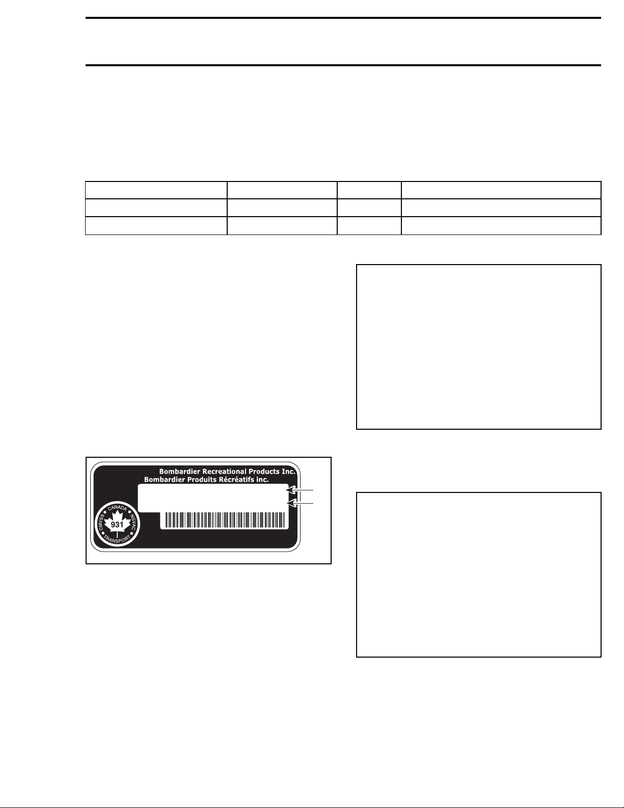
VEHICLE INFORMATION
Model Number
MANUFACTURED BY:
FABRIQUÉ PAR:
MFD. DATE FAB:
2BPS1234X2V000123
VIN / NIV:
12/2003
1234
MODEL:
2
1
3F8A, 3F8B, 3F8C
3G8A, 3G8B, 3G8C
Vehicle Identification Number (V.I.N.)
vmo2008-011-026_a
TYPICAL
1. Vehicle Identification Number (V.I.N.)
Engine Identification Number (E.I.N.)
MADE IN/FABRIQUÉ AU:
XXXXX
vmo2008-011-094_a
TYPICAL — VEHICLE IDENTIFICATION NUMBER LABEL
1. Serial number
2. Model number
vmr2008-002 IX
TYPE: ATV / VTT
vmo2008-011-026_b
1. Engine Identification Number (E.I.N.)

INTRODUCTION
ENGINE EMISSIONS
INFORMATION
Manufacturer's Responsibility
Manufacturers of ATVs engines must determine
the exhaust emission levelsfor each engine horsepower family and certify these engines with the
United States of America Environmental Protection Agency (EPA). An emissions control information label, showing emission levels and engine
specifications, must be placed on each vehicle at
the time of manufacture.
Dealer Responsibility
When performing service on ATVs that carry an
emissions control information label, adjustments
must be kept within published factory specifications.
Replacement or repair of any emission related
component must be executed in a manner that
maintains emission levels within the prescribed
certification standards.
Dealers are not to modify the engine in any manner that would alter the horsepoweror allow emission levels to exceed their predetermined factory
specifications.
Exceptions include manufacturer's prescribed
changes, such as altitude adjustments for example.
Owner Responsibility
The owner/operator is required to have engine
maintenance performed to maintain emission
levels within prescribed certification standards.
The owner/operator is not to, and should not allow anyone to modify the engine in any manner
that would alter the horsepower or allow emissions levels to exceed their predetermined factory
specifications.
The responsibilities listed above are general and
in no way a complete listing of the rules and regulations pertaining to the EPA requirements on exhaust emissions for ATVs products. For more detailed information on this subject, you may contact
the following locations:
FORALLCOURIERSERVICES:
U.S. Environmental Protection Agency
Office of Transportation and Air Quality
1310 L Street NW
Washington D.C. 20005
REGULAR US POSTAL MAIL:
1200 Pennsylvania Ave. NW
Mail Code 6403J
Washington D.C. 20460
INTERNET: http://www.epa.gov/otaq/
E-MAIL: otaqpublicweb@epa.gov
SELF-LOCKING FASTENERS
PROCEDURE
The following describes the most common application procedures when working with self-locking
fasteners.
Use a metal brush or a screw tap to clean the
hole properly then use a solvent, let act during 30
minutes and wipe off. The solvent utilization is to
ensure the adhesive works properly.
LOCTITE®APPLICATION
PROCEDURE
The following describes the most common application procedures when working with Loctite
products.
NOTE: Always use proper strength Loctite product as recommended in this manual.
EPA Emission Regulations
Some ATVs manufactured by BRP are certified
to the EPA as conforming to the requirements
of the regulations for the control of air pollution
from new ATV engines. This certification is contingent on certain adjustments being set to factory
standards. For this reason, the factory procedure
for servicing the product must be strictly followed
and, whenever practicable, returned to the original intent of the design.
X vmr2008-002
INTRODUCTION
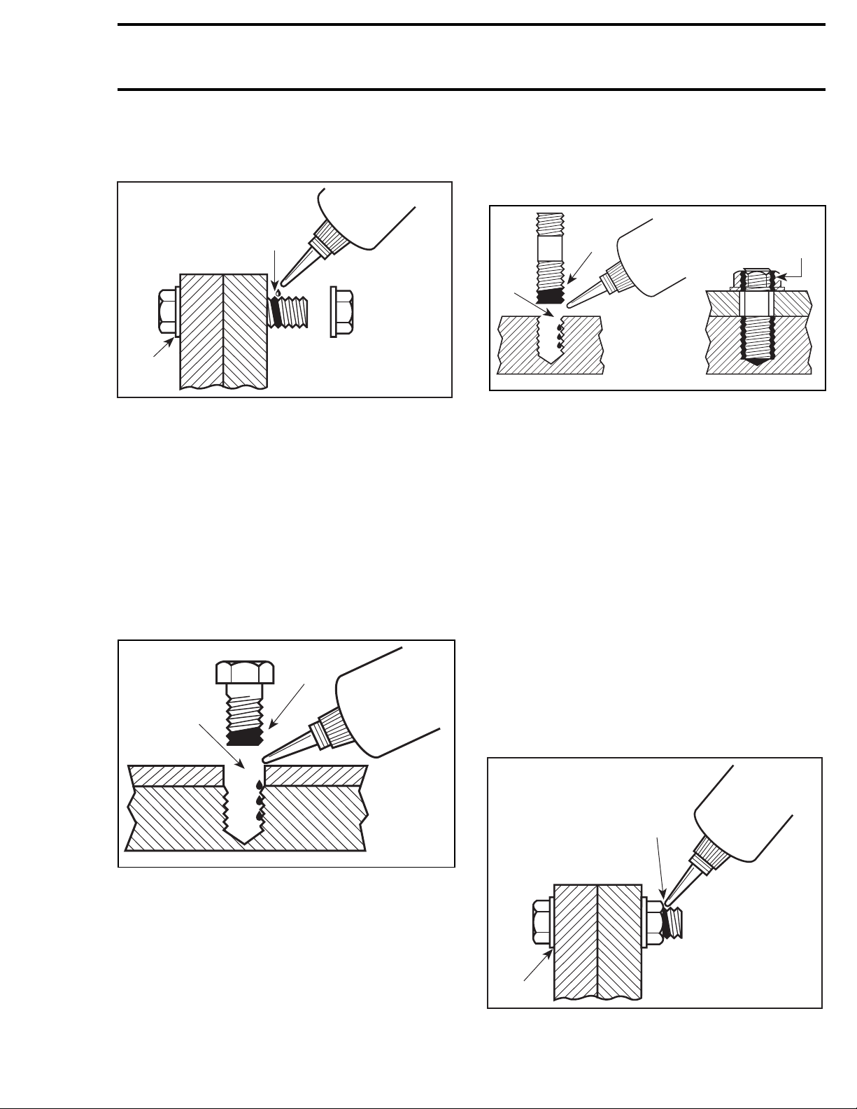
Threadlocker
Uncovered Holes (bolts and nuts)
1
2
A00A3LA
1. Apply here
2. Do not apply
Clean threads (bolt and nut) with solvent.
Apply Loctite Primer N (P/N 293 800 041) on
threads and allow to dry.
Choose proper strength Loctite threadlocker.
Fit bolt in the hole.
Apply a few drops of threadlocker at proposed
tightened nut engagement area.
Position nut and tighten as required.
Blind Holes
1
2
Apply several drops on screw threads.
Tighten as required.
Stud in Blind Holes
1
3
2
lmr2007-040-005_a
1. On stud threads
2. On hole threads
3. Onto nut threads
Clean threads (stud and hole) with solvent.
Apply Loctite Primer N (P/N 293 800 041) on
threads and allow to dry.
Put 2 or 3 drops of proper strength Loctite thread-
locker along the threaded hole.
NOTE: To avoid a hydro lock situation, do not apply
too much Loctite.
Apply several drops of proper strength Loctite on
stud threads.
Install stud.
Install cover, etc.
Apply drops of proper strength Loctite on uncov-
ered threads.
Tighten nuts as required.
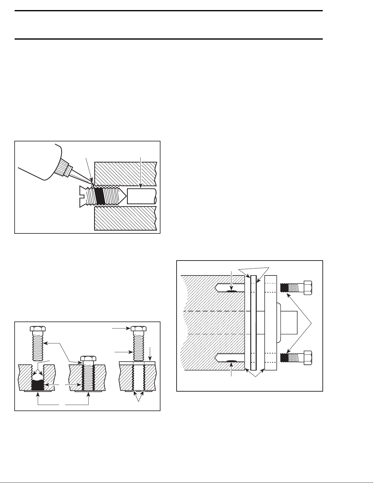
Preassembled Parts
1
lmr2007-040-004_a
1. On screw threads
2. On hole threads
Clean threads (screw and hole) with solvent.
Apply Loctite Primer N (P/N 293 800 041) on
threads (screw and nut) and allow to dry for 30
seconds.
Choose proper strength Loctite threadlocker.
Apply 2 or 3 drops along the threaded hole.
NOTE: Toavoid a hydro lock situation, do not apply
too much Loctite.
vmr2008-002 XI
2
A00A3OA
1. Apply here
2. Do not apply
Clean bolts and nuts with solvent.
INTRODUCTION
Assemble components.
Tighten nuts.
Apply drops of proper strength Loctite on bolt/nut
contact surfaces.
Avoid touching metal with tip of flask.
NOTE: For preventive maintenance on exist-
ing equipment, retighten nuts and apply proper
strength Loctite on bolt/nut contact surfaces.
Adjusting Screw
2
A00A3PA
1. Apply here
2. Plunger
1
Adjust screw to proper setting.
Apply drops of proper strength Loctite threadlock-
er on screw/body contact surfaces.
Avoid touching metal with tip of flask.
NOTE: if it is difficult to readjust, heat screw with
a soldering iron (232°C (450°F)).
Standard Thread Repair
Follow instructions on Loctite FORM-A-THREAD
81668 package.
If a plate is used to align bolt:
– Apply release agent on mating surfaces.
– Put waxed paper or similar film on the surfaces.
Twist bolt when inserting it to improve thread conformation.
NOTE: NOT intended for engine stud repairs.
Repair of Small Holes/Fine Threads
Option 1: Enlarge damaged hole, then follow
STANDARD THREAD REPAIR
procedure.
Option 2: Apply FORM-A-THREAD on the screw
and insert in damaged hole.
Permanent Stud Installation (light duty)
Use a stud or thread on desired length.
DO NOT apply release agent on stud.
STANDARD THREAD REPAIR
Do a
.
Allow to cure for 30 minutes.
Assemble.
Gasket Compound
21
Stripped Thread Repair
5
2
A00A3QA
1. Release agent
2. Stripped threads
3. Form-A-Thread
4. Tape
5. Cleaned bolt
6. Plate
7. New threads
8. Threadlocker
1
8
3
4
6
lmr2007-040-006_a
1
1. Proper strength Loctite
7
2. Loctite Primer N (P/N 293 800 041) and Loctite 518
(P/N 293 800 038) on both sides of gasket
3. Loctite Primer N only
3
Remove old gasket and other contaminants with
Loctite Chisel remover (P/N 413 708 500). Use a
mechanical mean if necessary.
NOTE: Avoid grinding.
Cleanbothmatingsurfaceswithsolvent.
XII vmr2008-002
1
INTRODUCTION
Spray Loctite Primer N on both mating surfaces
and on both sides of gasket. Allow to dry 1 or 2
minutes.
Apply Loctite 518 (P/N 293 800 038) on both sides
of gasket, using a clean applicator.
Place gasket on matingsurfaces and assemble immediately.
NOTE: If the cover is bolted to blind holes (above),
apply proper strength Loctite on the threads of
hole. Tighten.
If holes are sunken, apply proper strength Loctite
on bolt threads.
Tighten as usual.
Mounting on Shaft
Mounting with a Press
1
2
3
A00A3UA
1. Bearing
2. Proper strength Loctite
3. Shaft
Cleanshaft externalpart and element internal part.
Apply a strip of proper strength Loctite on shaft
circumference at insert or engagement point.
NOTE: Retaining compound is always forced out
whenappliedonshaft.
DO NOT use antiseize Loctite or any similar prod-
uct.
No curing period is required.
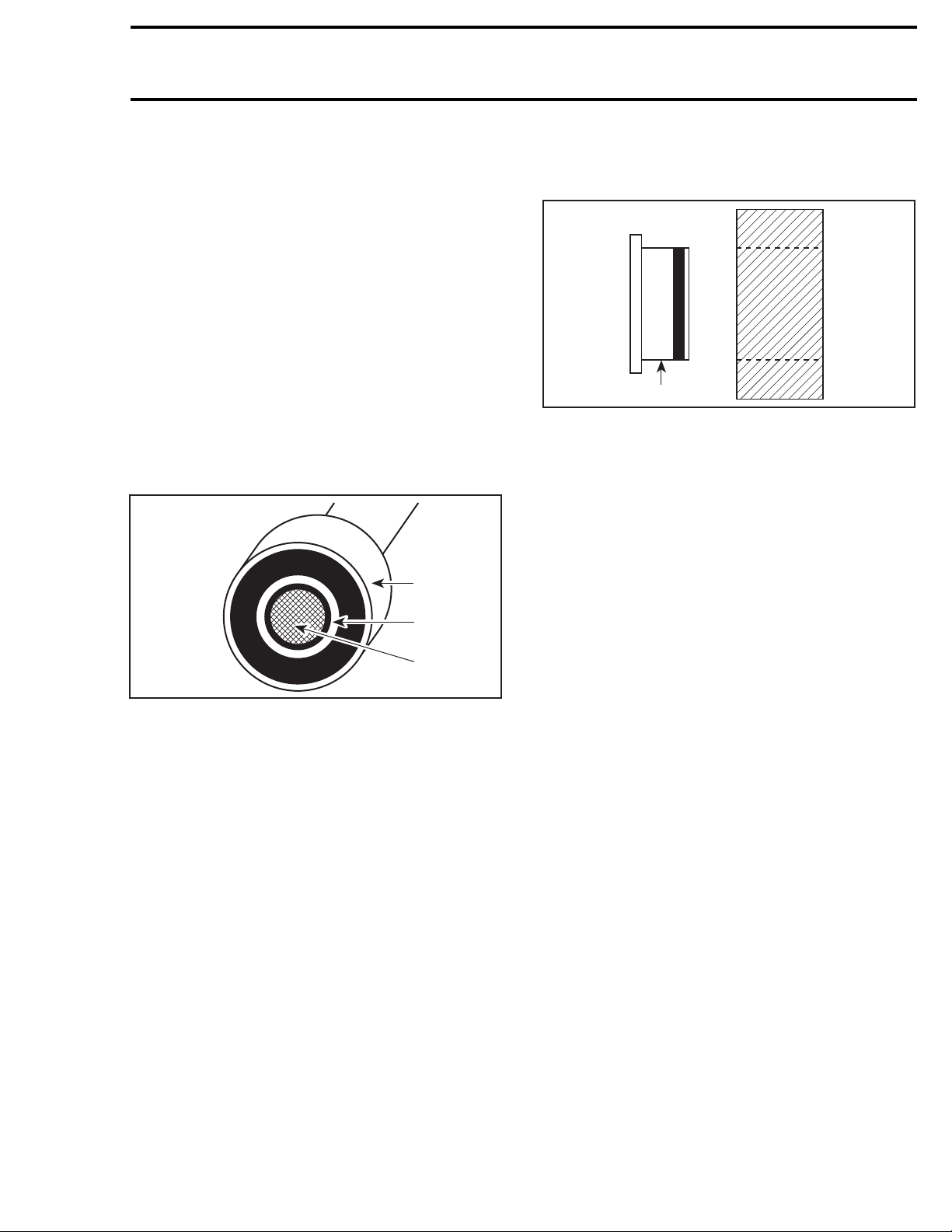
Case-In Components
Metallic Gaskets
A00A3VA
1. Proper strength Loctite
Clean inner housing diameter and outer gasket diameter.
Spray housing and gasket with Loctite Primer N
(P/N 293 800 041).
Apply a strip of proper strength Loctite on leading
edge of outer metallic gasket diameter.
NOTE: Any Loctite product can be used here. A
low strength liquid is recommended as normal
strength and gap are required.
Install according to standard procedure.
Wipe off surplus.
Allow it to cure for 30 minutes.
NOTE: Normally used on worn-out housings to
prevent leaking or sliding.
It is generally not necessary to remove gasket
compound applied on outer gasket diameter.
1
Mounting in Tandem
Apply retaining compound on internal element
bore.
Continue to assemble as shown above.
vmr2008-002 XIII
INTRODUCTION
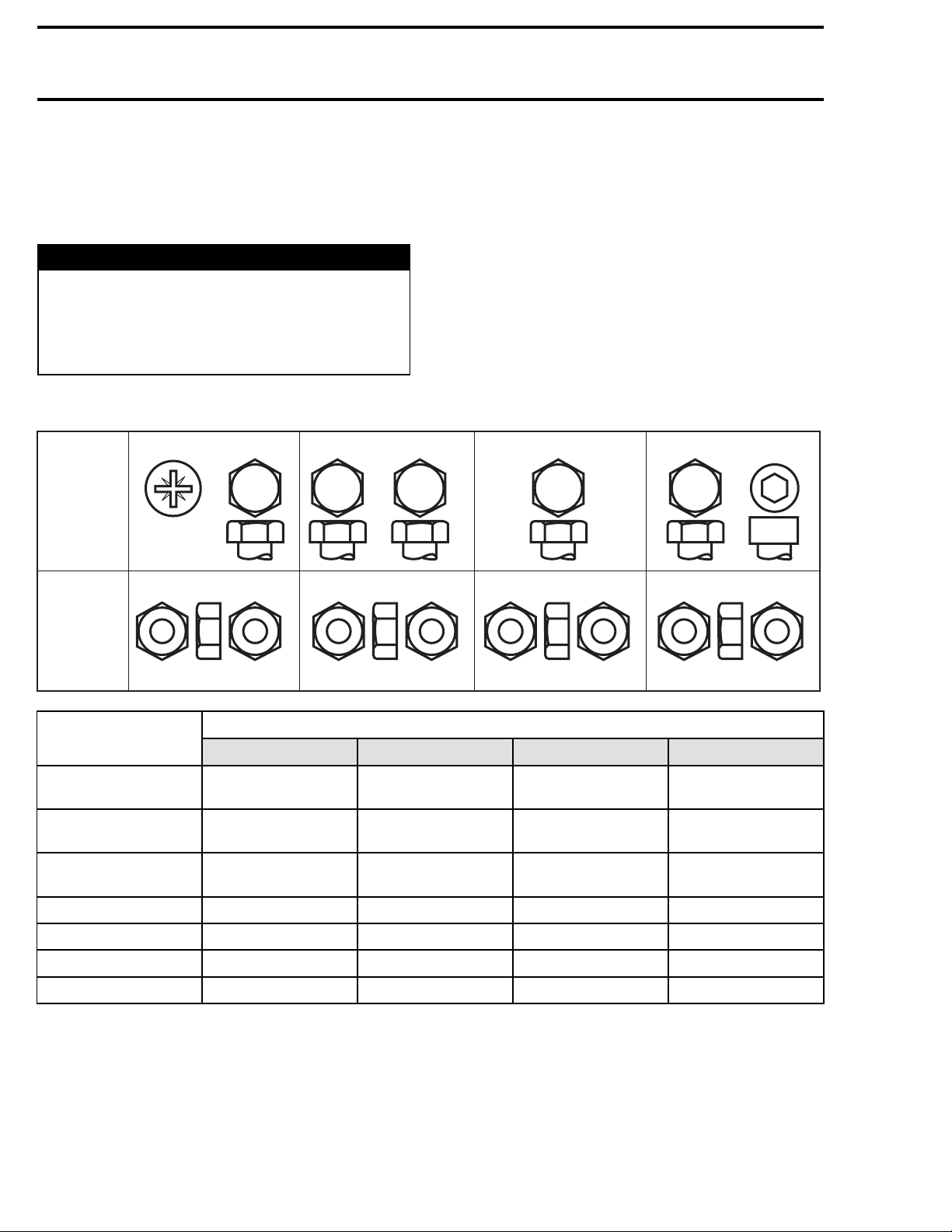
TIGHTENING TORQUES
Tighten fasteners to torque mentioned in exploded views and/or text. When they are not specified, refer to following table.
WARNING
Torque wrench tightening specifications
must strictly be adhered to.
Locking devices (e.g.: locking tabs, elastic
stop nuts, cotter pins, etc.) must be replaced
with new ones.
Property
markings
Property
markings
A00A8BS
class
and
head
class
and
nut
4.8
4.8
4.8
5
5
8.8
8.8
8.8
8
8
In order to avoid a poor assembling, tighten
screws, bolts or nuts in accordance with the
following procedure:
Manually screw all screws, bolts and/or nuts.
Apply the half of the recommended torque value.
CAUTION: Be sure to use the proper tightening
torque for the proper strength grade.
NOTE: When possible, always apply torque onthe
nut.
Torque to the recommended torque value.
NOTE: Always torque screws, bolts and/or nuts in
a criss-cross sequence.
9.8
9.8
9.8
10.9
10.9
10.9
10
12.9
12.9
12.9
12
10
12.9
12
FASTENER SIZE
M4
M5
M6
M8 15 N•m (133 lbf•in) 25 N•m (18 lbf•ft) 32 N•m (23 lbf•ft) 40 N•m (30 lbf•ft)
M10 29 N•m (21 lbf•ft) 48 N•m (35 lbf•ft) 61 N•m (45 lbf•ft) 73 N•m (53 lbf•ft)
M12 52 N•m (38 lbf•ft) 85 N•m (63 lbf•ft) 105 N•m (77 lbf•ft) 128 N•m (94 lbf•ft)
M14 85 N•m (63 lbf•ft) 135 N•m (100 lbf•ft) 170 N•m (125 lbf•ft) 200 N•m (148 lbf•ft)
5.8
Grade
1.5–2N•m
(13 – 18 lbf•in)
3–3.5N•m
(27 – 31 lbf•in)
6.5 – 8.5 N•m
(58 – 75 lbf•in)
FASTENER GRADE/TORQUE
8.8
Grade
2.5–3N•mN•m
(22 – 27 lbf•in)
4.5 – 5.5 N•m
(40 – 47 lbf•in)
8–12N•m
(71 – 106 lbf•in)
10.9
3.5–4N•m
(31 – 35 lbf•in)
7–8.5N•m
(62 – 75 lbf•in)
10.5 – 15 N•m
(93 – 133 lbf•in)
Grade
12.9
Grade
4–5N•m
(35 – 44 lbf•in)
8–10N•m
(71 – 89 lbf•in)
16 N•m (142 lbf•in)
XIV vmr2008-002

MANUAL INFORMATION
The manual is divided into many major sections as
you can see in the main table of contents at the
beginning of the manual.
Each section is divided in various subsections, and
again, each subsection has one or more division.
The illustrations show the typical construction of
the different assemblies and, in all cases, may not
reproduce the full detail or exact shape of the parts
shown, however, they represent parts which have
the same or a similar function.
CAUTION: Most components in the vehicles
are built with parts dimensioned in the metric
system. Most fasteners are metric and must
not be replaced by customary fasteners or
vice-versa. Mismatched or incorrect fasteners
could cause damage to the vehicle or possible
personal injury.
As many of the procedures in thismanual are interrelated, we suggest that before undertaking any
task, you read and thoroughly understand the entire section or subsection in which the procedure
is contained.
A number of procedures throughout the book require the use of special tools. Before starting any
procedure, be sure that you have on hand all required tools, or approved equivalents.
The use of RIGHT and LEFT indications in the text,
always refers to the driving position (sitting on the
vehicle).
INTRODUCTION
vmr2008-002-001_a
TYPICAL
1. Left
2. Right
This manual uses technical terms which may be
different from the ones of the
PARTS CATALOGS
.
When ordering parts always refer to the specific
model
vmr2008-002 XV
PARTS CATALOGS
.
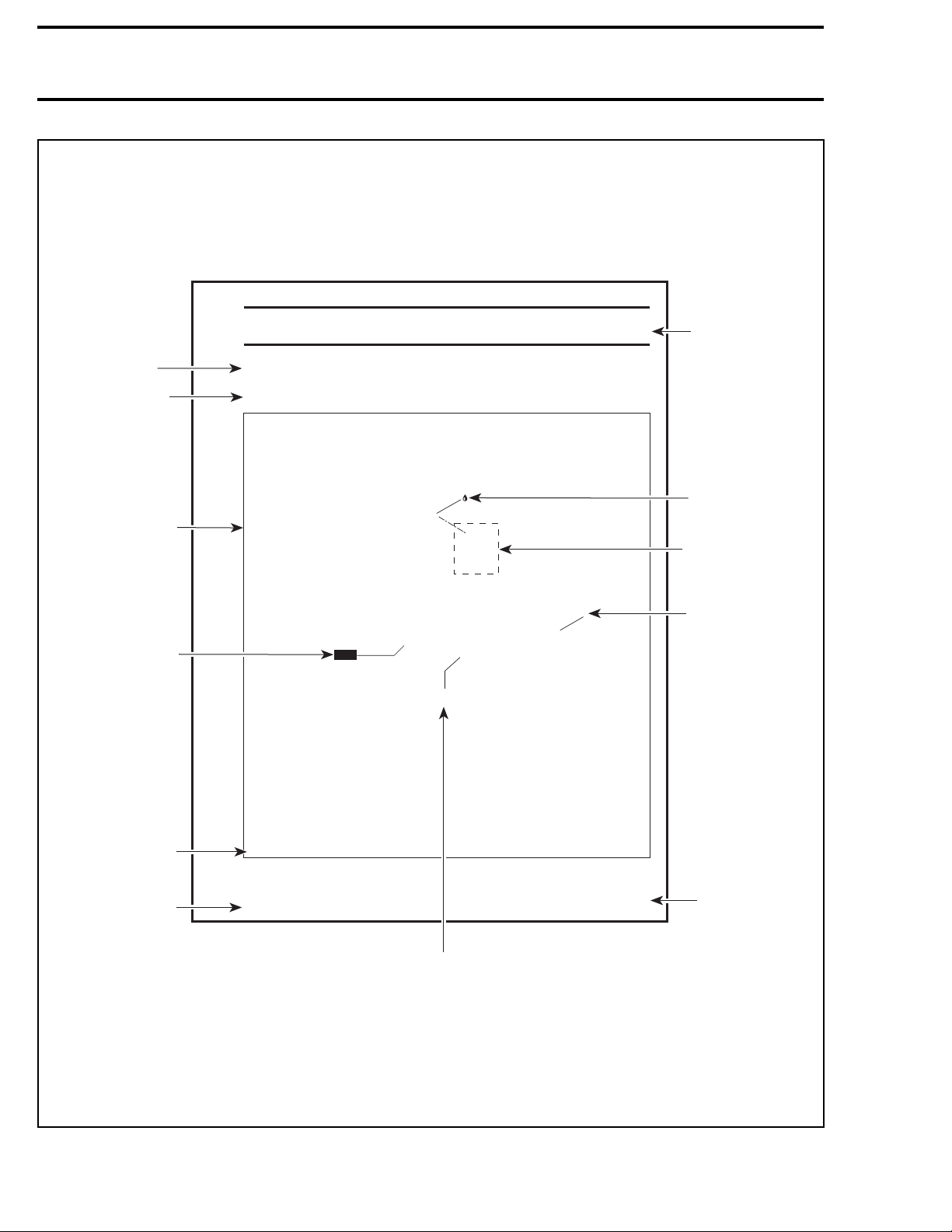
INTRODUCTION
TYPICAL PAGE
Subsection title
Indicates applicable
models.
Exploded view assists
you in identifying parts
and their related
positions.
NEW indicates that the
part must be replaced
with a new one.
MAGNETO
Models
NEW
Loctite 243
5 Nm
(44 lbfin)
Section 06 ENGINE
Subsection 01 (MAGNETO)
Model
Page heading
indicates section
and subsection.
Drop represents a
service product
to be applied.
Dotted box contains
parts applicable to a
specific model.
Bold face number
1
is used to identify
a part referred to
the text.
Illustration number
for publishing process.
Document number for
publishing process.
XXX0000
mmr2008-001
55
Page number
Specific torque applicable to this installation.
cations.
Typical_iso_2008_en
CAUTION: Pay attention to torque specifi
Some of these are in
Use appro
lbfin instead of lbfft.
priate torque wrench.
XVI vmr2008-002
Tittle in bold
indicates category
of information to be
carried out.
Reference to a
specific section
or subsection.
Indicates component
procedures apply to.
Indicates specific
procedure to be
carried out.
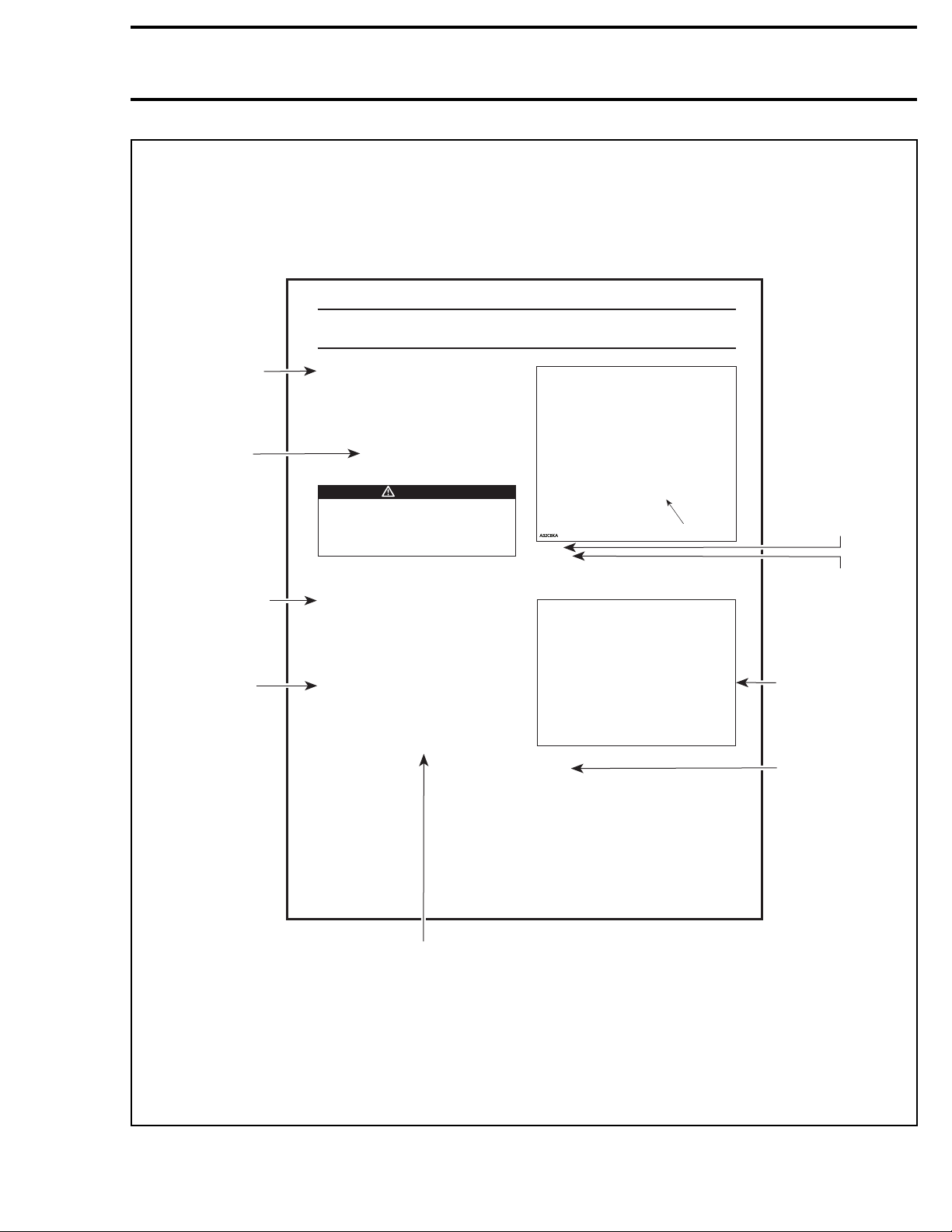
TYPICAL PAGE
GENERAL
GENERAL
NOTE:
NOTE:
The following procedures can be done
The following procedures can be done
without removing the engine.
without removing the engine.
During assembly/installation, use the torque val-
During assembly/installation, use the torque values and service products as in the exploded
ues and service products as in the exploded
views.
views.
Clean threads before applying a threadlocker. Re-
Clean threads before applying a threadlocker. Refer to the
fer to the
SELF-LOCKING FASTENERS
SELF-LOCKING FASTENERS
TITE APPLICATION
TITE APPLICATION
this manual for complete procedure.
this manual for complete procedure.
Torque wrench tightening specifications
Torque wrench tightening specifications
must be strictly adhered to.
must be strictly adhered to.
Locking devices (e.g.: locking tabs, elastic
Locking devices (e.g.: locking tabs, elastic
stop nuts, self-locking fasteners, etc.) must
stop nuts, self-locking fasteners, etc.) must
be replaced with new ones.
be replaced with new ones.
PROCEDURES
PROCEDURES
MAGNETO FLYWHEEL
MAGNETO FLYWHEEL
Magneto Flywheel Cleaning
Magneto Flywheel Cleaning
Clean all metal components in a non-ferrous metal
Clean all metal components in a non-ferrous metal
cleaner.
cleaner.
CAUTION:
CAUTION:
a clean cloth.
a clean cloth.
Magneto Flywheel Removal
Magneto Flywheel Removal
Remove muffler, refer to the
Remove muffler, refer to the
section.
section.
Remove acoustic panel.
Remove acoustic panel.
Remove rewind starter.
Remove rewind starter.
Remove starting pulley
Remove starting pulley
sections at the beginning of
sections at the beginning of
WARNING
WARNING
Clean magneto flywheel using only
Clean magneto flywheel using only
EXHAUST SYSTEM
EXHAUST SYSTEM
no. 2
no. 2
.
.
and
and
LOC-
LOC-
Section 03 ENGINE
Subsection 09 (MAGNETO SYSTEM)
Subsection 09 (MAGNETO SYSTEM)
TYPICAL
TYPICAL
1. Starting pulley
1. Starting pulley
NOTE:
NOTE:
To remove starting pulley bolts, hold mag-
To remove starting pulley bolts, hold mag-
neto flywheel with a socket as shown.
neto flywheel with a socket as shown.
mmr2007-016-002
TYPICAL
TYPICAL
Models
Models
Remove the connecting flange retaining the
Remove the connecting flange retaining the
rewind starter to the engine housing.
rewind starter to the engine housing.
Section 03 ENGINE
1
1
INTRODUCTION
TYPICAL
indicates a general
view which may
not represent exact
details.
Call-outs pertaining
to above illustration.
Illustration always
follows text to which
it applies.
Italic bold face type-
setting indicates a
procedure applicable
to a specific
model(s).
mmr2008-001
57
Bold face number following part
name refers to exploded view
at beginning of subsection.
typical_txt_2008_en
vmr2008-002 XVII

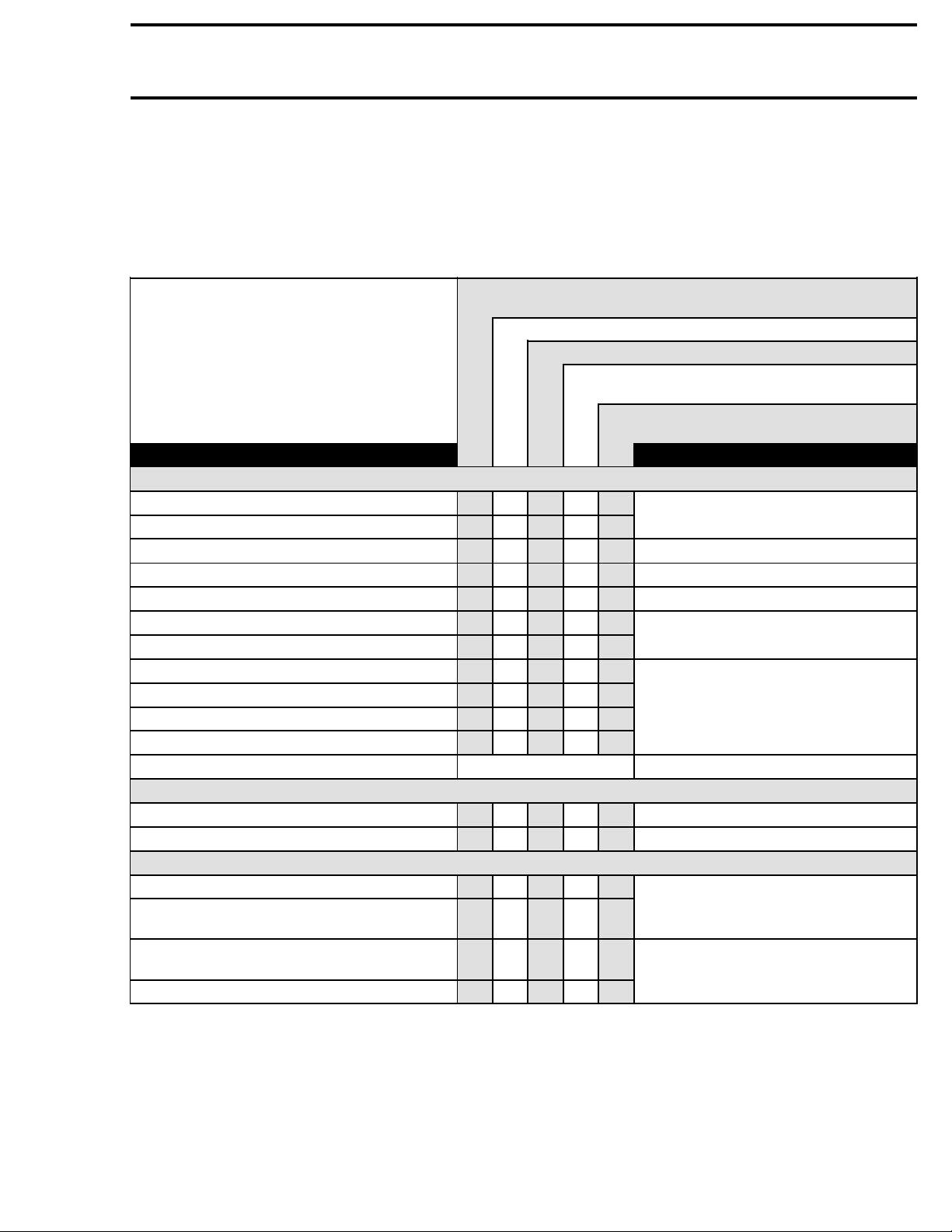
Section01MAINTENANCE
Subsection 01 (MAINTENANCE CHART)
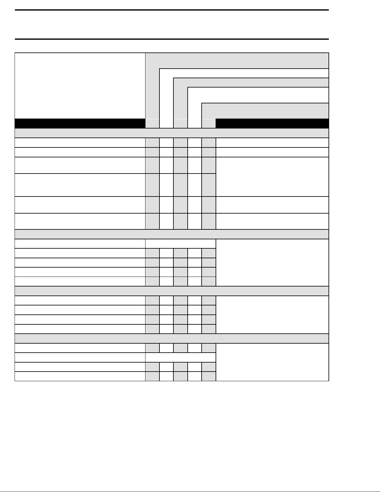
MAINTENANCE CHART
The schedule should be adjusted according to operating conditions and use.
NOTE: The chart gives an equivalence between number of hours and months/year. Perform the mainte-
nance operation to whatever time comes first.
IMPORTANT: Intensive use of the ATV, will require greater frequency of inspection and maintenance.
10HOURSOR30DAYSOR400KM(250mi)
(The initial maintenance is very important and must not be neglected.)
A:
ADJUST
C:
CLEAN
I:
INSPECT
L:
LUBRICATE
R:
REPLACE
PART/TASK REFER TO
ENGINE
Engine oil
(1)
and filter R R
Oil reservoir strainer C
Engine valves I, A I, A
Engine mounting fasteners I I
Air filter
(2)
Exhaust system I I
Spark arrester C
Coolant
II
Cooling system pressure test I I
Radiator cap pressure test I I
Radiator
(3)
I, C I, C
Clutch
ENGINE MANAGEMENT (EMS)
EMS sensors I I
EMS fault codes
II
FUEL SYSTEM
Throttle body I I, L
Throttle cable I, A
Fuel lines, fuel rail, connections, check valves
and fuel tank pressure test
II
Fuel pump pressure I
EVERY 25 HOURS OR 1250 KM (800 mi)
EVERY 50 HOURS OR 2500 KM (1600 mi)
EVERY 100 HOURS OR 5000 KM (3100 mi) OR
1YEAR
EVERY 200 HOURS OR 10000 KM (6200
mi) OR 2 YEAR
LUBRICATION SYSTEM
CYLINDER HEAD/CYLINDER
ENGINE REMOVAL/NSTALLATION
(3)
R
AIR INTAKE SYSTEM
EXHAUST SYSTEM
(4)
R
COOLING SYSTEM
(5)
CLUTCH
ELECTRONIC FUEL INJECTION
ENGINE MANAGEMENT
I, A,
ELECTRONIC FUEL INJECTION
L
FUEL TANK/FUEL PUMP
vmr2008-003 1
Section 01 MAINTENANCE
Subsection 01 (MAINTENANCE CHART)
10HOURSOR30DAYSOR400KM(250mi)
(The initial maintenance is very important and must not be neglected.)
ADJUST
A:
CLEAN
C:
INSPECT
I:
LUBRICATE
L:
REPLACE
R:
PART/TASK REFER TO
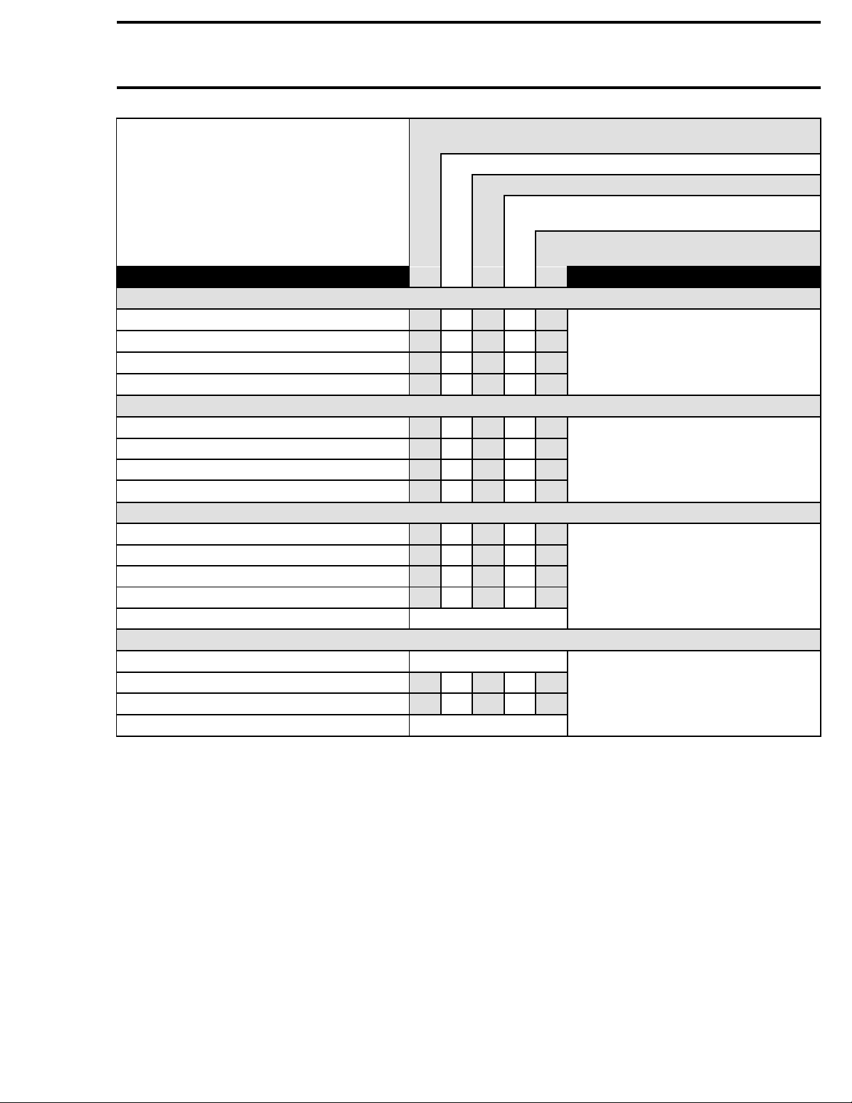
ELECTRICAL SYSTEM
Spark plugs
(6)
II R
Battery connections I I
ECM connectors
(visual inspection without disconnecting)
Electrical connections and fastening
(ignition system, starting system, fuel
II
injectors etc.)
Ignition switch, start button and engine
run/stop switch
Lighting system (HI/LO intensity, brake light,
beam aiming, etc.)
II
II
DRIVE SYSTEM
Drive chain and slider
Drive chain sprockets
Drive chain tensioner
(3)
(8)
IIR
II
Rear axle bearings I I
Rear axle and rear axle nut
(8)
II
STEERING
Handlebar fasteners I I
Steering column and bearing
(3)
II
Tie rod ends I I
Front wheel alignment I, A I, A
WHEELS/TIRES
Wheel nuts/studs I I
Tires
Front wheel bearings I I
Rear wheel hub L
EVERY 25 HOURS OR 1250 KM (800 mi)
EVERY 50 HOURS OR 2500 KM (1600 mi)
I
(7)
(9)
EVERY 100 HOURS OR 5000 KM (3100 mi) OR
1YEAR
EVERY 200 HOURS OR 10000 KM (6200
mi) OR 2 YEAR
IGNITION SYSTEM
CHARGING SYSTEM
ELECTRICAL CONNECTORS
IGNITION SYSTEM
and
STARTING SYSTEM
FUSES/LIGHTS
DRIVE CHAIN/REAR AXLE
STEERING SYSTEM
WHEELS/TIRES
2 vmr2008-003
Subsection 01 (MAINTENANCE CHART)
10HOURSOR30DAYSOR400KM(250mi)
(The initial maintenance is very important and must not be neglected.)
ADJUST
A:
CLEAN
C:
INSPECT
I:
LUBRICATE
L:
REPLACE
R:
PART/TASK REFER TO
REAR SUSPENSION
Swing arm I I L
Suspension linkage
I, L I, L
Shock absorber
Shock absorber lower pivot L
FRONT SUSPENSION
Suspension arms
II,L
Ball joints boots I I
Ball joints
(3)
II
Shock absorbers
BRAKES
Brake fluid I I R
Brake pads
(3)
Brake discs I
Brake hoses I
Brake line fittings
BODY/FRAME
Skidplate(DS450X)
Frame fastener I I
Frame I
Operator's seat and its fasteners
EVERY 25 HOURS OR 1250 KM (800 mi)
EVERY 50 HOURS OR 2500 KM (1600 mi)
EVERY 100 HOURS OR 5000 KM (3100 mi) OR
1YEAR
I
I
I
(10)
(10)
(10)
Section01MAINTENANCE
EVERY 200 HOURS OR 10000 KM (6200
mi) OR 2 YEAR
REAR SUSPENSION
FRONT SUSPENSION
BRAKES
BODY AND FRAME
Inspect oil level at every ride.
(1)
Clean at every ride.
(2)
More often under severe use such as dusty area, sand, snow, wet or muddy conditions.
(3)
Every 50 hours, check coolant strength.
(4)
Inspectadjustmentateveryride.
(5)
Make sure that the spark plug gap is correct.
(6)
Inspect, adjust and lubricate at every ride.
(7)
Check tightness.
(8)
Check tire pressure and wear at every ride.
(9)
Inspect at every ride.
(10)
vmr2008-003 3


Section01MAINTENANCE
Subsection 02 (PRESEASON PREPARATION)
PRESEASON PREPARATION
Prior to use vehicle, proper vehicle preparation is
required after a storage period.
Any worn, broken or damaged parts found during
the storage procedure should have been replaced.
If not, proceed with the replacement.
Using the maintenance chart, performed items in
the column indicated: EVERY 100 HOURS OR
5000 KM (3100 mi) OR 1 YEAR.
vmr2008-004-001_a
1. Use this column
Furthermore, proceed with the following:
Vehicles Prepared as per Storage Procedure
Remove rag from muffler.
Test drive vehicle to confirm proper operation.
Vehicles Not Prepared as per Storage Procedure
Replaceengineoilandfilter.
Drain fuel tank and fill with fresh fuel.
Test drive vehicle to confirm proper operation.
vmr2008-004 5


Section01MAINTENANCE
Subsection 03 (STORAGE PROCEDURE)
STORAGE PROCEDURE
SERVICE PRODUCTS
Description Part Number Page
BRP fuel stabilizer................................................................. 413 408 600 .............................................7
storage oil............................................................................. 413 711 600 .............................................7
storage oil (US)..................................................................... 413 711 900 .............................................7
IftheATVisnotusedoristobestoredforan
extended period of time, more than 4 months, be
sure to perform the storage procedures described
below.
FUEL SYSTEM
Fuel System Protection
With the additives used in today's fuel, it is critical
to use the BRP fuel stabilizer (P/N 413 408 600)
or an equivalent to prevent fuel deterioration and
fuel system gumming. Follow the manufacturer's
instructions for proper use.
CAUTION: Fuel stabilizer should be added
prior to engine lubrication to ensure fuel system components protection against varnish
deposits.
Pour fuel stabilizer in fuel tank. Fill up fuel tank.
Do not drain fuel system.
ENGINE
Engine Oil and Filter Replacement
Change engine oil and filter. Refer to
TION SYSTEM
.
Engine Internal Lubrication
Engine internal parts must be lubricated to protect
them from rust formation during the storage period.
WARNING
This procedure must only be performed in a
well-ventilated area. Do not run engine during storage period.
Proceed as follows:
Start the engine and allow it to run at idle speed
until the engine reaches its operating temperature.
Stop the engine.
LUBRICA-
Remove spark plugs andspray storage oil (P/N 413
711 600) into cylinder.
NOTE: For US citizens, use storage oil (US)
(P/N 413 711 900) only.
CAUTION: Do not inject storage oil into throttle
body bore to avoid blocking idle bypass valve.
Press start button, 1 or 2 seconds maximum, to
lubricate cylinder.
Reinstall the spark plugs.
ELECTRICAL SYSTEM
Battery Removal
Remove the battery. Store it in dry and cool place.
Refer to
BATTERYinCHARGING SYSTEM
.
COOLING SYSTEM
Coolant Inspection
Test coolant density using an antifreeze hydrometer.
NOTE: Follow manufacturer's instructions for
proper use.
Change coolant if necessary. Refer to
SYSTEM
.
COOLING
VEHICLE
Vehicle Cleaning
Clean vehicle. Refer to
ucts to be used.
CAUTION: Never use a high pressure washer
to clean the vehicle. USE LOW PRESSURE ONLY (like a garden hose). The high pressure can
cause electrical or mechanical damages.
Vehicle Protection
Using clean rag, block the muffler. The rag will
prevent the intrusion of small animals, leaves or
other debris.
BODY
for cleaning prod-
vmr2008-005 7

Section 01 MAINTENANCE
Subsection 03 (STORAGE PROCEDURE)
Protect the vehicle with a cover to prevent dust
accumulation during storage.
CAUTION: The vehicle has to be stored in a
cool and dry place. If vehicle is stored outside,
it must be covered with an opaque tarpaulin.
This will prevent sun rays and grime from affecting plastic components and vehicle finish.
8 vmr2008-005

Section01MAINTENANCE
Subsection 04 (SPECIAL PROCEDURES)
SPECIAL PROCEDURES
SERVICE PRODUCTS
Description Part Number Page
XP-S Lube............................................................................. 293 600 016 .............................................9
TURN OVER
When vehicle is turned over or stays tilted on the
side, put the vehicle back on its wheels, then wait
3 to 5 minutes before starting the engine.
Inspect air filter housing drain tube for oil accumulation, if any oil is found, clean air filter and air filter
housing. Refer to
Check oil level in oil tank and refill if necessary.
Start engine and let it run, around 1 minute, then
stop engine. Check oil level immediately, refer to
LUBRICATION SYSTEM
dure.
AIR INTAKE SYSTEM
section for proper proce-
section.
ATV IMMERSION
ATV Submerged for a Long Time
(More than One Hour)
Engine
Disassemble engine to clean the internal parts and
check if there is no rust or corrosion onany internal
parts. Refer to
Drainairfilterhousingthencleananddryairfilter.
Remove muffler and empty it. Let muffler dry
then reinstall it on the vehicle.
Fuel System
Flush fuel tank and refill with new gas.
Lubricate the throttle body. Refer to
ENGINE
IC FUEL INJECTION
Chassis
Look for water in:
– Brake system (replace brake fluid)
– Chain tensioner.
Lubricate all cables. Check if the cables operate
properly.
Lubricate suspension arms and swing arm.
Lubricate drive chain.
Spray all metal parts with XP-S Lube (P/N 293 600
016).
sections.
ELECTRON-
.
ATV Submerged for a Short Time
(Less than Oone Hour)
Fuel System
Drain air filter housing then clean and dry air filter.
Lookforwaterinfueltank, in doubt, flush fuel tank
and refill with new gas.
Engine
Check if engine oil is contaminated (oil will be
milky). If so, perform the following instructions:
Drainengineoil.
Refill engine at the proper level with the recom-
mended oil. Crank engine several times.
Remove spark plugs.
Add a small quantity of engine oil in cylinder
(approximately 2 teaspoonfuls). Do not reinstall
spark plugs at this moment.
Check condition of spark plugs. If spark plugs appear good reinstall them, if not install new ones.
Start the engine and allow it to run at idle speed
until the engine reaches its operating temperature.
Stop the engine.
Change engine oil and filter.
NOTE: Change oil as many times as necessary,
until there is no white appearance in engine oil.
Chassis
Lubricate all cables. Check if the cables operate
properly.
Lubricate suspension arms and swing arm.
Lubricate drive chain.
Spray all metal parts with XP-S Lube (P/N 293 600
016).
vmr2008-006 9

 Loading...