

Page 1
See Warranty on page 10 for important information about commercial use of this product.
Operating Instructions
Please read and save these instructions. Read carefully before attempting to assemble, install, operate or maintain the product described.
Protect yourself and others by observing all safety information. Failure to comply with instructions could result in personal injury and/or
property damage! Retain instructions for future reference.
Portable Air Compressor
Table of Contents
Descripion . . . . . . . . . . . . . . . . . . . . . . 1
Unpacking . . . . . . . . . . . . . . . . . . . . . . 1
Safety Guidelines . . . . . . . . . . . . . . . . 1
General Safety Information . . . . . . . . 1
Introduction . . . . . . . . . . . . . . . . . . . . 3
Assembly . . . . . . . . . . . . . . . . . . . . . . . 4
Operation . . . . . . . . . . . . . . . . . . . . . . 6
Maintenance . . . . . . . . . . . . . . . . . . . . 6
Troubleshooting Chart . . . . . . . . . . . . 8
Warranty . . . . . . . . . . . . . . . . . . . . . . 10
Description
Air compressor units are intended
to provide compressed air to power
pneumatic tools and operate spray
guns. The pumps supplied are oil
lubricated. A small amount of oil
carryover is present in the compressed
air stream. Applications requiring air
free of oil or water should have the
appropriate filter installed. The air
compressor unit must be mounted
as described in the instructions on
a solid floor. Any other use of these
units will void the warranty and the
manufacturer will not be responsible
for problems or damages resulting from
such misuse.
Unpacking
After unpacking the unit, inspect
carefully for any damage that may
have occurred during transit. Make sure
to tighten fittings, bolts, etc., before
putting unit into service.
Do not operate unit
if damaged during
shipping, handling or use. Damage may
result in bursting and cause injury or
property damage.
READ & FOLLOW ALL INSTRUCTIONS
SAVE THESE INSTRUCTIONS
DO NOT DISCARD
Breathable Air Warning
This compressor/pump is NOT
Safety Guidelines
This manual contains information
that is very important to know and
understand. This information is
provided for SAFETY and to PREVENT
EQUIPMENT PROBLEMS. To help
recognize this information, observe the
following symbols.
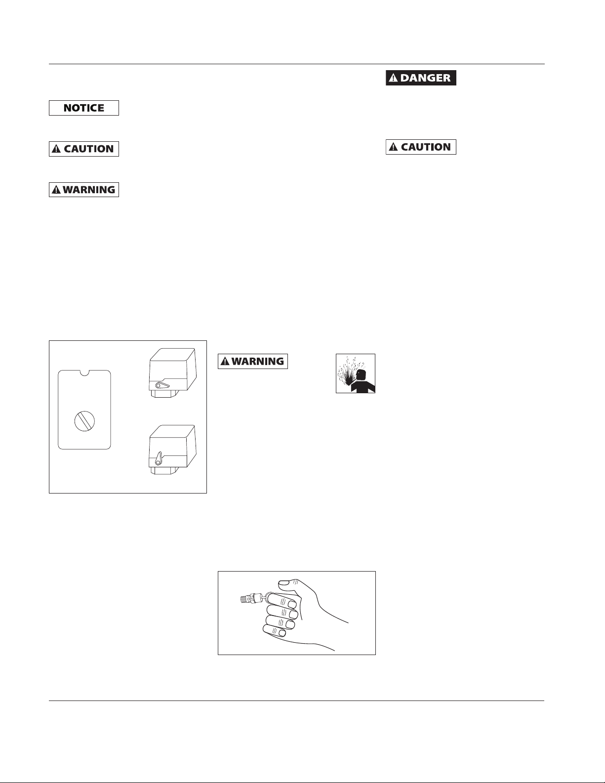
Danger indicates an
imminently
hazardous situation which, if not
avoided, WILL result in death or serious
injury.
Warning indicates a
potentially
hazardous situation which, if not
avoided, COULD result in death or
serious injury.
Caution indicates a
potentially
hazardous situation which, if not
avoided, MAY result in minor or
moderate injury.
Notice indicates
important
information, that if not followed, may
cause damage to equipment.
NOTE: Information that requires special
equipped and should NOT be
used “as is” to supply breathing
quality air. For any application of
air for human consumption, you
must fit the air compressor/pump
with suitable in-line safety and
alarm equipment. This additional
equipment is necessary to
properly filter and purify the air
to meet minimal specifications
for Grade D breathing as
described in Compressed
Gas Association Commodity
Specification G 7.1, OSHA 29
CFR 1910. 134, and/or Canadian
Standards Associations (CSA).
DISCLAIMER OF WARRANTIES
In the event the compressor is
used for the purpose of breathing
air application and proper inline safety and alarm equipment
is not simultaneously used,
existing warranties are void, and
Campbell Hausfeld disclaims any
liability whatsoever for any loss,
personal injury or damage.
attention.
General Safety Information
You can
CALIFORNIA PROPOSITION 65
This product or
its power cord may
contain chemicals known to the State
of California to cause cancer and birth
defects or other reproductive harm.
Wash hands after handling.
dust when you cut, sand, drill
or grind materials such as
wood, paint, metal, concrete,
cement, or other masonry. This dust
often contains chemicals known to
cause cancer, birth defects, or other
reproductive harm. Wear protective
gear.
create
© 2008
REMINDER: Keep your dated proof of purchase for warranty purposes!
Attach it to this manual or file it for safekeeping.
IN625500AV 4/08
Page 2
Operating Instructions
General Safety Information
(Continued)
GENERAL SAFETY
Since the air compressor and other
components (material pump, spray
guns, filters, lubricators, hoses, etc.)
used, make up a high pressure pumping
Never
compressor without a
beltguard. This unit can
start automatically without
warning. Personal injury or property
damage could occur from contact with
moving parts.
9. Do not wear loose clothing or
system, the following safety precautions
must be observed at all times:
1. Read all manuals included
with this product
carefully. Be thoroughly
familiar with the
controls and the proper use of the
MANUAL
Compressor parts may be hot
even if the unit is stopped.
10. Keep fingers away from a
equipment.
2. Follow all local electrical and safety
codes as well as in the United States,
the National Electrical Codes (NEC)
11. If the equipment should start to
and Occupational Safety and Health
Act (OSHA).
3. Only persons well acquainted with
these rules of safe operation should
be allowed to use the compressor.
12. To reduce fire hazard, keep engine/
4. Keep visitors away and NEVER allow
children in the work area.
5. Wear safety glasses and
use hearing protection
when operating the unit.
6. Do not stand on or use the unit as a
handhold.
7. Before each use, inspect compressed
air system and electrical components
for signs of damage, deterioration,
weakness or leakage. Repair or
replace defective items before using.
8. Check all fasteners at frequent
An ASME code
with a setting no higher than 150 psi
MUST be installed in the tank for this
compressor. The ASME safety valve
must have suffi cient fl ow and pressure
ratings to protect the pressurized
components from bursting.
See compressor
for maximum operating pressure.
Do not operate with pressure switch
or pilot valves set higher than the
maximum operating pressure.
13. Never attempt to adjust ASME safety
intervals for proper tightness.
Motors,
equipment and controls can
cause electrical arcs that
will ignite a fl ammable gas
or vapor. Never operate or repair in or
near a fl ammable gas or vapor. Never
store fl ammable liquids or gases in the
vicinity of the compressor.
electrical
Never use plastic
compressed air. Serious injury or death
could result.
operate
jewelry that will get caught in the
moving parts of the unit.
running compressor; fast moving
and hot parts will cause injury and/
or burns.
vibrate abnormally, STOP the engine/
motor and check immediately for
the cause. Vibration is generally a
warning of trouble.
motor exterior free of oil, solvent, or
excessive grease.
safety relief valve
specifi cation decal
valve. Keep safety valve free from
paint and other accumulations.
(PVC) pipe for
Never
attempt
to repair or modify a tank!
Welding, drilling or any other
modifi cation will weaken the
tank resulting in damage from rupture
or explosion. Always replace worn,
cracked or damaged tanks.
Drain liquid from
tank daily.
14. Tanks rust from moisture build-up,
which weakens the tank. Make sure
to drain tank regularly and inspect
periodically for unsafe conditions
such as rust formation and corrosion.
15. Fast moving air will stir up dust
and debris which may be harmful.
Release air slowly when draining
moisture or depressurizing the
compressor system.
SPRAYING PRECAUTIONS
Do not
spray
fl ammable materials in
vicinity of open fl ame or near
ignition sources including the
compressor unit.
16. Do not smoke when spraying paint,
insecticides, or other flammable
substances.
17. Use a face mask /
respirator when spraying
and spray in a well
ventilated area to prevent
health and fire hazards.
18. Do not direct paint or other sprayed
material at the compressor. Locate
compressor as far away from the
spraying area as possible to minimize
overspray accumulation on the
compressor.
19. When spraying or cleaning with
solvents or toxic chemicals, follow
the instructions provided by the
chemical manufacturer.
www.chpower.com
2
Page 3

Introduction
R efer to Figures 1a or 1b to locate the
following items.
Pressure switch - Auto/Off Switch - In
the "auto" position, the compressor
shuts off automatically when tank
pressure reaches the maximum preset
pressure. After air is used from the tank
and drops to a preset low level, the
pressure switch automatically turns the
motor back on. In the "off" position,
the compressor will not operate. This
switch should be in the "off" position
when connecting or disconnecting the
power cord from the electrical outlet.
When the pressure switch turns the
motor off you will hear air leaking out
of the pressure switch unloader valve
for a short time. This releases the air
pressure from the discharge tube and
allows the compressor to restart easier.
For units without a manual switch,
whenever the procedures call for
turning the switch to the OFF position,
use the switch at the disconnect instead.
Regulator - The regulator controls the
amount of air pressure released at the
hose outlet (Sold separately).
Discharge Tube
Check Valve
Handle
ASME Safety Valve - This valve
automatically releases air if the tank
pressure exceeds the preset maximum.
Discharge tube - This tube carries
compressed air from the pump to the
check valve. This tube becomes very hot
during use. To avoid the risk of severe
burns, never touch the discharge tube.
To avoid the risk of
severe burns, never
touch the discharge tube.
Check valve - One-way valve that
allows air to enter the tank, but
prevents air in the tank from flowing
back into the compressor pump.
Handle - Designed to move the
compressor.
Never use the
handle to lift the
unit completely off the ground. Handle
is intended only for pushing or pulling
product.
Belt Guard - Covers the belt, motor
pulley and flywheel.
Never
operate
compressor without a
beltguard. This unit can
start automatically without
warning. Personal injury or property
damage could occur from contact with
moving parts.
Intake Filter
Belt
Guard
Breather/Dipstick
& Oil Fill Hole
Tank Drain Valve - This valve is located
on the bottom of the tank. Use this
valve to drain moisture from the tank
daily to reduce the risk of corrosion.
Reduce tank pressure below 10 psi,
then drain moisture from tank daily to
avoid tank corrosion. Drain moisture
from tank(s) by opening the drain valve
located underneath the tank.
T ank Pressure Gauge - Indicates
amount of air pressure stored in tank.
Hose Pressure Gauge - Indicates
amount of air pressure in hose used to
operate tools. This pressure is increased
or decreased by the regulator.
Discharge Tube Belt Guard
Intake Filter
Handle
Tan k
Pressure
Gauge
Tan k
Pressure
Switch
Breather/
Dipstick
& Oil Fill
Hole
Figure 1a
Drain
Petcock
Safety
Valve
Pressure
Switch
Regulator
Tan k
Tank Pressure
Gauge
Hose Pressure
Gauge
3
Drain
Petcock
Figure 1b
www.chpower.com
Page 4
Operating Instructions
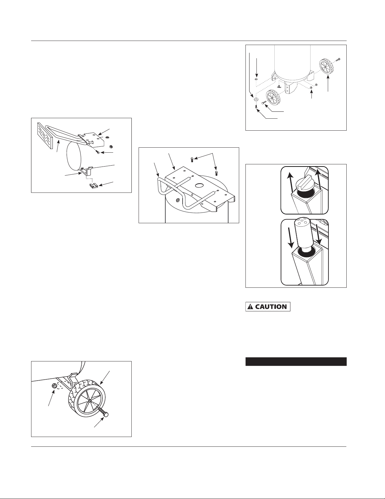
Assembly
HORIZONTAL TANK UNITS ONLY
HANDLE ASSEMBLY
1. Remove the handle screw from the
tank baseplate, if preinstalled.
2. Insert handle into both sides of tank
baseplate. Squeeze handle to fit into
special openings in baseplate (See
Figure 2).
Tan k
Baseplate
Handle
Bracket
Figure 2
3. Place a short piece of wood against
end of handle and tap with a mallet
or hammer until the hole in the
handle lines up with the hole in the
baseplate.
4. Insert and tighten the handle screw
into the hole in the baseplate and
through the handle. Make sure the
screw goes through the handle.
WHEEL ASSEMBLY
The items marked with an asterisk (*)
in Figure 3 were shipped loose with the
unit. Assemble as follows:
1. Insert shoulder bolt through wheel
hub with the bolt head on the
opposite side of the protruding hub
section.
2. For the 8 inch diameter wheels,
insert the shoulder bolt in the lowest hole of the tank axle iron and
tightly secure with locknut.
Lock Nut*
Handle
Screw
Rubber
Foot
Wheel*
3. For the 10 inch diameter wheels,
insert the shoulder bolt in the upper
hole in the tank axle iron and tightly
secure with the locknut. Repeat this
step on the opposite side.
When assembled, the tank must sit level
or slope slightly towards the tank drain
valve to allow tank to drain properly.
VERTICAL TANK UNITS ONLY
HANDLE ASSEMBLY
Insert four handle screws through holes
in handle and tighten to tank baseplate
(See Figure 4).
Tank Baseplate Handle Screw
Handle
Figure 4
FOOT ASSEMBLY
The items marked with an asterisk (*)
were shipped loose with the unit (See
Figure 5).
1. Tilt unit to allow access to front foot
and secure properly to ensure unit
does not tip over.
2. Insert bolt through foot and bracket.
The foot should be on the lower side
of bracket.
3. Tightly secure with the lock nut.
Repeat on opposite side.
WHEEL ASSEMBLY
The items marked with an asterisk (*)
were shipped loose with the unit (See
Figure 5).
1. Insert shoulder bolt through wheel
hub. The bolt hex head should be on
the opposite side of protruding hub
center.
2. Feed the shoulder bolt through
the hole on the tank axle iron and
tightly secure with the locknut.
Repeat on the opposite side.
Foot*
Nut*
Wheel*
Lock Nut*
Shoulder Bolt*
Bolt*
Figure 5
BREATHER INSTALLATION
Remove cap from oil fill opening. Install
breather (found in parts bag with this
manual). See Figure 6.
Remove
Cap
Install
Breather
Figure 6
LUBRICATION
CHECK OIL LEVEL.
SOME UNITS INCLUDE
OIL. Follow lubrication instructions
before operating compressor.
Ensure oil drain extension and cap has
been installed (if included) then remove
the breather (See Figure 7) and fill
pump oil according to the chart.
Pump Approx. Oil Capacity
VS260000KB 6.0 oz
VT470000KB 8.5 oz
VT480000KB 8.5 oz
See specification label on air tank for
pump model number and refer to the
chart for the proper oil capacity.
Figure 3
www.chpower.com
Shoulder Bolt
4
Page 5
Assembly (Continued)
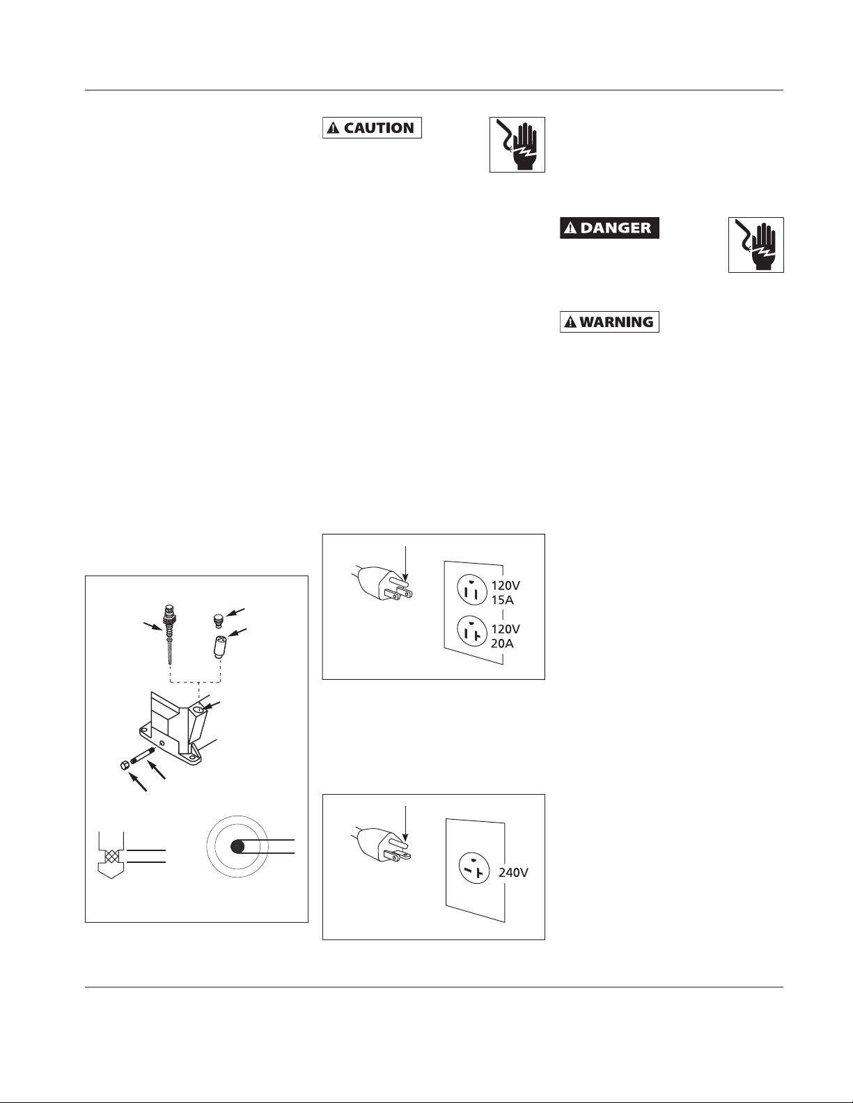
OIL DRAIN EXTENSION
Some models include an oil drain
extension and cap (found with the
owner’s manual). Install the oil drain
extension and cap before adding oil to
the pump. To avoid oil leaks, it is highly
recommended to apply Teflon® tape or
plumber’s putty to the threads on each
end of the oil drain extension. Screw
the cap onto one end of the extension.
Remove the oil drain plug from the base
of the pump and install the oil drain
extension (See Figure 7).
OIL
Use SAE 30 industrial grade air
compressor oil or full synthetic motor
oil like Mobil 1 10W30. Do not use
regular automotive oil such as 10W-30.
Additives in motor oil can cause valve
deposits and reduce pump life. For
maximum pump life, drain and replace
oil after the first hour of run time.
Proper oil fill level is illustrated in
Figure 7.
For pumps with an oil sight glass, oil
level can be monitored and maintained
as shown in Figure 7.
ELECTRICAL DATA
Overheating, short-circuiting
and fi re damage will result
from inadequate wiring.
The 120 volt, 15 amp units can be
operated on a 120 volt 15 amp circuit
under the following conditions:
1. No other electrical appliances or
lights are connected to the same
branch circuit.
2. Voltage is 120 Volts.
3. Circuit is equipped with a 15 amp
circuit breaker or a 15 amp slow
blow fuse type T (For Canada use
Typ e D).
4. The length of copper wire between
the outlet and circuit breaker is not
longer than 40 feet of 14 AWG or 70
feet of 12 AWG.
If the above conditions cannot be met
or if nuisance tripping of the current
protection device occurs, it may be
possible to operate the compressor from
a 120 volt 20 amp circuit. See Figure 8.
Grounded OutletGround Pin
GROUNDING INSTRUCTIONS
This product must be grounded. In
the event of an electric short circuit,
grounding reduces the risk of electrical
shock by providing an escape wire for
the electric current. Unit is equipped
with a cord that has a grounding prong.
Improper
use of
grounding plug can result in
a risk of electrical shock.
NOTE: Do not use grounding
adapter.
When converting
to an alternate
voltage, be sure the green ground wire
of the cord connects to the ground pin
of the plug and to the metal body of the
pressure switch.
Dipstick
Breather
Cap*
Max
Low
Dipstick Oil Read
Figure 7
Full
Add
Oil Fill Cap
(Dispose of
properly)
Breather
OR
Add Oil
Oil Drain Extension*
Full
Add
Sight Glass
* Not included with all models.
Figure 8
Check motor data plate for 240 volt
compatability. A 240 volt unit must be
operated on a 240 volt circuit. The cord
must only plug into a 240 volt grounded
outlet and may require a new cord and
plug. See Figure 9.
Grounded OutletGround Pin
Figure 9
www.chpower.com
5
Page 6
Operating Instructions
Operation
START-UP
This compressor
pump must be fi lled
with oil before startup. See lubrication
section.
Do not attach air
tools to open end of
the hose until start-up is completed and
the unit checks OK.
Never disconnect
threaded joints with
pressure in tank!
1. Check for proper oil level. See
Lubrication Section.
2. Open tank drain valve.
3. Turn pressure switch lever or knob
to OFF position and plug in power
cord.
4. Turn pressure switch lever or knob to
AUTO position and run unit for 30
minutes to break in the pump parts
8. Attach hose, then add chuck or
other tool to open end of hose. Plug
in powercord. Turn pressure switch
lever to AUTO position. When full
pressure is reached turn regulator
knob clockwise until desired outlet
pressure is achieved.
9. After use, turn pressure switch lever
or knob to the Off position.
10. If compressor is not used for a long
time period, bleed air from line
and use drain valve to drain water
from the tank. Then, follow the
maintenance schedule.
NOTE: Electric models are equipped
with a pressure switch that
automatically turns the motor OFF
when the tank pressure reaches a preset
level. After air is used from the tank and
drops to a preset low level, the pressure
switch automatically turns the motor
back on.
(See Figure 10).
Maintenance
Disconnect, tag and lock out
power source, then release
Lever - Off
A
U
T
F
O
F
/
O
Knob
Auto/Off
Figure 10
Lever - Auto
5. Turn regulator knob fully
counterclockwise. Compressor will
build to maximum preset pressure
and shut off.
6. Turn regulator knob clockwise to
cause air to bleed off. Compressor
will restart at preset pressure.
7. Turn pressure switch lever or knob to
OFF position and unplug powercord.
Slowly turn regulator knob clockwise
to allow all air pressure to be
released. Do not proceed to the next
step until the tank pressure reaches
zero (0).
all pressure from the system
before attempting to install, service,
relocate or perform any maintenance.
All repairs should be performed by an
authorized service representative.
FOR EFFICIENT OPERATION:
Perform the following test to verify free
operation of the safety valve weekly
and follow maintenance schedule.
1. Pull ring on safety valve and allow
the ring to snap back to normal
position (see Figure 11). This valve
automatically releases air if the
tank pressure exceeds the preset
maximum.
Figure 11
Do not attempt to
valve. This valve should be checked
occasionally. If air leaks after the ring
has been released, or the valve is stuck
and cannot be actuated by the ring, the
safety valve must be replaced.
A large amount of
be released if this valve is actuated with
pressure in the tank.
tamper with this
fast moving air will
2. With motor OFF and unplugged,
clean debris from motor, flywheel,
tank, air lines and pump cooling fins.
TECHNICAL SERVICE
For information regarding the operation
or repair of this product, please call
1-800-543-6400.
Storage
1. When not in use, hose and
compressor should be stored in a
cool dry place.
2. Tanks should be drained of moisture.
and hose should be disconnected
and hung with open ends down to
allow any moisture to drain.
3. Protect the electrical cord from
possible damage by winding the
cord loosely around the handle of
the unit or coiling the cord up.
www.chpower.com
6
Page 7

MOISTURE IN COMPRESSED AIR
Moisture in compressed air will form
into droplets as it comes from an air
compressor pump. When humidity is high
or when a compressor is in continuous
use for an extended period of time, this
moisture will collect in the tank. When
using a paint spray or sandblast gun,
this water will be carried from the tank
through the hose, and out of the gun as
droplets mixed with the spray material.
IMPORTANT: This condensation will cause
water spots in a paint job, especially when
spraying other than water based paints. If
sandblasting, it will cause the sand to cake
and clog the gun, rendering it ineffective.
A fi lter in the air line, located as near to
the gun as possible, will help eliminate
this moisture.
Notes
MAINTENANCE SCHEDULE
OPERATION DAILY WEEKLY MONTHLY 3 MONTHS
CHECK OIL LEVEL
DRAIN TANK
CHECK AIR FILTER
CHECK SAFETY VALVE
CLEAN UNIT
CHECK BELT TIGHTNESS
CHANGE OIL
TORQUE REQUIREMENTS (in/lbs)
Model
Compressor
Head Bolts
VS 100-125 50-120
VT 225-300 50-120
Bearing
Cap Bolts
●
●
●
●
●
●
●
www.chpower.com
7
Page 8
Operating Instructions
Troubleshooting Chart
Symptom Possible Cause(s) Corrective Action
Low discharge pressure 1. Air demand exceeds pump capacity 1. Reduce air demand or use a compressor with more capacity.
2. Air leaks 2. Listen for escaping air. Apply soap solution to all fittings and
3. Restricted air intake 3. Clean the air filter element.
4. Blown gaskets 4. Replace any gaskets proven faulty on inspection.
5. Leaking or damaged valves 5. Remove head and inspect for valve breakage, misaligned valves,
Pump overheating causes
air filter to melt
1. Insulating gasket between filter and
head is missing
2. Broken valves/blown gasket 2. Replace valves or install new gasket.
Excessive noise (knocking) 1. Loose motor or compressor pulley 1. Loose motor or compressor pulleys are a very common cause of
2. Lack of oil in crankcase 2. Check for proper oil level; if low, check for possible damage to
3. Worn connecting rod 3. Replace connecting rod. Maintain oil level and change oil more
4. Worn piston pin bores 4. Remove piston assemblies from the compressor and inspect for
5. Piston hitting the valve plate 5. Remove the compressor head and valve plate and inspect for
6. Noisy check valve in compressor
system
Large quanity of oil in
1. Worn piston rings 1. Replace with new rings. Maintain oil level and change oil more
the discharge air
NOTE: In an oil lubricated
compressor there will
always be a small amount
of oil in the air stream.
Water in discharge air /
tank
Motor hums and runs
2. Compressor air intake restricted 2. Clean filter. Check for other restrictions in the intake system.
3. Excessive oil in compressor 3. Drain down to full level.
4. Wrong oil viscosity 4. Use Mobil 1
Normal operation. The amount of
water increases with humid weather
1. Use of extension cord 1. Do not use an extension cord. Use longer air hose with larger
slowly or not at all
2. Malfunctioning check valve or
unloader valve
3. Low voltage 3. Check with voltmeter, check reset switch on motor. If reset switch
4. Malfunctioning pressure switch contacts will not close
connections. Bubbles will appear at points of leakage. Tighten or
replace leaking fittings or connections.
damaged valve seats, etc. Replace defective parts and reassemble.
Install a new head gasket
each time the head is removed
1. Install gasket.
compressors knocking. Tighten pulley clamp bolts and set-screws.
bearings. Dirty oil can cause excessive wear.
frequently.
excess wear. Replace excessively worn piston pin or pistons, as
required. Maintain oil level and change oil more frequently.
carbon deposits or other foreign matter on top of piston. Replace
head and valve plate using new gasket. See Lubrication section for
recommended oil.
6. Replace.
Do not disassemble check
valve with air pressure in tank
frequently.
®
10W-30.
1. Drain tank more often. At least daily.
2. Add a filter to reduce the amount of water in the air line.
diameter.
2. Replace check valve, unloader valve or pressure switch.
Do not disassemble check
valve with air pressure in tank
trips repeatedly, find and correct the cause. See next item.
4. Repair or replace pressure switch.
www.chpower.com
8
Page 9
Troubleshooting Chart (Continued)
Symptom Possible Cause(s) Corrective Action
Reset mechanism cuts
out repeatedly or fuses
blow repeatedly
Tank does not hold
pressure when
compressors off and the
shut off valve is closed
Pressure switch
continuously blows air
out the unloader valve
Pressure switch does
not release air when
the unit shuts off
Excessive vibration 1. Loose fasteners 1. Tighten.
1. Too many devices on same circuit 1. Limit the circuit to the use of only the air compressor.
2. Incorrect fuse size or circuit breaker 2. Be sure that fuses or circuit breakers are rated properly.
3. Malfunctioning check valve
4. Pressure switch set too high 4. Adjust or replace.
5. Loose wiring 5. Check all electrical connections.
6. Malfunctioning motor 6. Replace motor.
1. Worn check valve
2. Check all connections and fittings
for leaks
3. Check tank for cracks or pin holes 3. Replace tank. Never repair a damaged tank.
Malfunctioning check valve Replace the check valve if the unloader valve bleeds off constantly.
Malfunctioning unloader valve on
pressure switch
2. Belt needs replaced 2. Replace with correct size.
3. Belt alignment 3. Align flywhell and pulley.
3. Replace check valve.
Do not disassemble check
1. Replace check valve.
Do not disassemble check
2. Tighten.
Do not disassemble check
Replace the pressure switch if it does not release the pressure for a
short period of time when the unit shuts off.
Do not disassemble check
valve with air pressure in tank
valve with air pressure in tank
valve with air pressure in tank
valve with air pressure in tank
www.chpower.com
9
Page 10

Operating Instructions
Limited Warranty
1. DURATION: From the date of purchase by the original purchaser as follows: One Year, Two Years, Three Years, Four Years, or Five Years as
indicated on product specification label.
2. WHO GIVES THIS WARRANTY (WARRANTOR): Campbell Hausfeld / Scott Fetzer Company, 100 Production Drive,
Harrison, Ohio, 45030, Telephone: (800) 543-6400
3. WHO RECEIVES THIS WARRANTY (PURCHASER): The original purchaser (other than for purposes of resale) of the Campbell Hausfeld
compressor.
4. WHAT PRODUCTS ARE COVERED BY THIS WARRANTY: Any Campbell Hausfeld air compressor.
5. WHAT IS COVERED UNDER THIS WARRANTY: Parts and Labor to remedy substantial defects due to material and workmanship during
the first year of ownership with the exceptions noted below. Parts only to remedy substantial defects due to material and workmanship
during remaining term of coverage with exceptions noted below.
6. WHAT IS NOT COVERED UNDER THIS WARRANTY:
A. Implied warranties, including those of merchantability and FITNESS FOR A PARTICULAR PURPOSE ARE LIMITED FROM THE DATE
OF ORIGINAL PURCHASE AS STATED IN THE DURATION. If the compressor is used for commercial, industrial or rental purposes, the
warranty will apply for ninety (90) days from the date of purchase. Two-stage compressors are not limited to a ninety (90) day warranty
when used in commercial or industrial applications. Some States do not allow limitations on how long an implied warranty lasts, so the
above limitations may not apply to you
B. ANY INCIDENTAL, INDIRECT, OR CONSEQUENTIAL LOSS, DAMAGE, OR EXPENSE THAT MAY RESULT FROM ANY DEFECT, FAILURE,
OR MALFUNCTION OF THE CAMPBELL HAUSFELD PRODUCT. Some States do not allow the exclusion or limitations of incidental or
consequential damages, so the above limitation or exclusion may not apply to you.
C. Any failure that results from an accident, purchaser’s abuse, neglect or failure to operate products in accordance with instructions
provided in the owner’s manual(s) supplied with compressor.
D. Pre-delivery service, i.e. assembly, oil or lubricants, and adjustment.
E. Items or service that is normally required to maintain the product, i.e. lubricants, filters and gaskets, etc.
F. Gasoline engines and components are expressly excluded from coverage under this limited warranty. The Purchaser must comply with
the warranty given by the engine manufacturer which is supplied with the product
G. Additional items not covered under this warranty:
1. Excluded items pertaining to All Compressors
a. Any component damaged in shipment or any failure caused by installing or operating unit under conditions not in accordance
with installation and operation guidelines or damaged by contact with tools or surroundings.
b. Pump or valve failure caused by rain, excessive humidity, corrosive environments or other contaminants.
c. Cosmetic defects that do not interfere with compressor functionality.
d. Rusted tanks, including but not limited to rust due to improper drainage or corrosive environments.
e. The following components are considered normal wear items and are not covered after the first year of ownership. Electric
motor, check valve, pressure switch, regulator, pressure gauges, hose, tubing, pipe, fittings and couplers, screws, nuts,
hardware items, belts, pulleys, flywheel, air filter and housing, gaskets, seals, oil leaks, air leaks, oil consumption or usage,
piston rings.
f. Tank drain valves.
g. Damage due to incorrect voltage or improper wiring.
h. Other items not listed but considered general wear parts.
i. Pressure switches, air governors, load/unload devices, throttle control devices and safety valves modified from factory
settings.
j. Damage from inadequate filter maintenance.
k. Induction motors operated with electricity produced by a generator.
2. Excluded items specific to Lubricated Compressors:
a. Pump wear or valve damage caused by using oil not specified.
b. Pump wear or damage caused by any oil contamination.
c. Pump wear or damage caused by failure to follow proper oil maintenance guidelines, operation below proper oil level or
operation without oil.
H. Labor, service call, or transportation charges after the first year of ownership of stationary compressors. Stationary compressors are
defined as not including a handle or wheels.
7. RESPONSIBILITIES OF WARRANTOR UNDER THIS WARRANTY: Repair or replace, at Warrantor’s option, compressor or component which is
defective, has malfunctioned and/or failed to conform within duration of the warranty period.
8. RESPONSIBILITIES OF PURCHASER UNDER THIS WARRANTY:
A. Provide dated proof of purchase and maintenance records.
B. Call Campbell Hausfeld (800-543-6400) to obtain your warranty service options. Freight costs must be borne by the purchaser.
C. Use reasonable care in the operation and maintenance of the products as described in the owner’s manual(s).
D. Repairs requiring overtime, weekend rates, or anything beyond the standard manufacturer warranty repair labor reimbursement rate.
E. Time required for any security checks, safety training, or similar for service personnel to gain access to facility.
F. Location of unit must have adequate clearance for service personnel to perform repairs and easily accessible.
9. WHEN WARRANTOR WILL PERFORM REPAIR OR REPLACEMENT UNDER THIS WARRANTY: Repair or replacement will be scheduled and
serviced according to the normal work flow at the servicing location, and depending on the availability of replacement parts.
This Limited Warranty applies in the U.S., Canada and Mexico only and gives you specific legal rights. You may also have other rights which
vary from State to State or country to country.
www.chpower.com
10
Page 11

Voir la Garantie à la page 20 pour de l’information importante sur l’utilisation commercial de ce produit.
Instructions d’Utilisation et Manual de Pièces
Veuillez lire et conserver ces instructions. Lire attentivement avant de commencer à assembler, installer, faire fonctionner ou entretenir
l'appareil décrit. Protégez-vous et les autres en observant toutes les informations sur la sécurité. Négliger d'appliquer ces instructions peut
résulter en des blessures corporelles et/ou en des dommages matériels ! Conserver ces instructions pour références ultérieures.
Compresseurs d’Air Portatifs
Table des matières
Descripion . . . . . . . . . . . . . . . . . . . . . 11
Déballage . . . . . . . . . . . . . . . . . . . . . 11
Directives de Sécurité . . . . . . . . . . . . 11
G énéralités sur la Sécurité . . . . . . . . 11
Introduction . . . . . . . . . . . . . . . . . . . 13
Montage . . . . . . . . . . . . . . . . . . . . . . 14
Fonctionnement . . . . . . . . . . . . . . . . 16
Entretien . . . . . . . . . . . . . . . . . . . . . . 16
Guide de Dépannage . . . . . . . . . . . . 18
Garantie. . . . . . . . . . . . . . . . . . . . . . . 20
Description
Les modèles de compresseurs d’air sont
conçus pour fournir de l’air comprimé
aux outils pneumatiques et pour faire
fonctionner les pistolets vaporistateurs.
Les pompes fournies sont graissées à
l’huile. Un peu d’huile résiduelle est
présent dans le débit d’air comprimé.
Installer les filtres appropriés pour les
applications qui requièrent de l’air libre
d’huile ou d’eau. Le compresseur d’air
doit être monté selon les instructions,
sur un plancher solide. Autres usages
de ces modèles nieront la garantie et le
fabricant ne sera pas responsable pour
les problèmes ou dommages résultant
de l’usage incorrect.
Déballage
Dès que l’appareil est déballé,
l’inspecter attentivement pour tout
signe de dommages en transit. S’assurer
de resserrer tous les raccords, boulons,
etc. avant de le mettre en service.
LIRE ET SUIVRE TOUTES LES
INSTRUCTIONS
CONSERVER CES INSTRUCTIONS
NE PAS JETER
Directives de Sécurité
Ce manuel contient de l’information
très importante qui est fournie pour
la SÉCURITÉ et pour ÉVITER LES
PROBLÈMES D’ÉQUIPEMENT. Rechercher
les symboles suivants pour cette
information.
Danger indique
une situation
hasardeuse imminente qui RÉSULTERA
en perte de vie ou blessures graves.
Avertissement
indique une
situation hasardeuse potentielle
qui PEUT résulter en perte de vie ou
blessures graves.
Attention indique
une situation
hasardeuse potentielle qui PEUT résulter
en blessures.
Avis indique de
l’information
importante pour éviter le dommage de
l’équipement.
REMARQUE: L’information qui exige
une attention spéciale.
Généralités sur la Sécurité
PROPOSITION 65 DE CALIFORNIE
Ce produit ou son
cordon peuvent
contenir des produits chimiques qui, de
l’avis de l’État de Californie, causent le
cancer et des anomalies congénitales
ou autres problèmes de reproduction.
Lavez-vous les mains après la
manipulation.
Vous
pouvez
créer de la poussière en
coupant, ponçant, perçant
ou meulant les matériaux
tels que le bois, la peinture, le métal, le
béton, le ciment ou autre maçonnerie.
Cette poussière contient souvent des
produits chimiques reconnus pour
causer le cancer, les déformations
congénitales ou autres problèmes de la
reproduction. Porter de l’équipement de
protection.
Avertissement D’Air
Respirable
Ce compresseur/pompe n’est
pas équipé pour et ne devrait
pas être utilisé “comme soi”
pour fournir de l’air respirable.
En cas d’applications d’air pour
la consommation humaine, le
compresseur d’air/pompe doit
être équipé avec de l’équipement
de sécurité en canalisation
et d’alarme. Cet équipement
additionnel est nécessaire
pour filtrer et purifier l’air afin
d’atteindre les spécifications
minimales pour la respiration
Grade D décrites dans le
Compressed Gas Association
Commodity Specification G
7.1 - 1966, OSHA 29 CFR 1910.
134, et/ou Canadian Standards
Associations (CSA).
DÉNÉGATION DES GARANTIES
Si le compresseur est utilisé pour
les applications d’air respirable
et l’équipement de sécurité en
canalisation et d’alarme n’est
pas utilisé simultanément, les
garanties en existance seront
annulées, et Campbell Hausfeld
nie toute responsabilité pour
n’importe quelle perte, blessure
ou dommage.
© 2008
MÉMENTO: Gardez votre preuve datée d'achat à fin de la garantie!
Joignez-la à ce manuel ou classez-la dans un dossier pour plus de sécurité.
11 Fr
IN625500AV 4/08
Page 12

Instructions d’utilisation
Généralités sur la Sécurité
(Suite)
GÉNÉRALITÉS SUR LA SÉCURITÉ
Puisque le compresseur d’air et les
autres pièces détachées (pompe,
pistolets, filtres, graisseurs, tuyaux,
etc.) font partie d’un système de haute
pression, il est nécessaire de suivre les
précautions suivantes:
1. Lire attentivement tous
manuels compris avec ce
produit. Se familiariser
avec ce produit, ses
commandes et son utilisation.
2. Suivre tous les codes de sécurité
et d’électricité locaux ainsi que les
codes des É-U; National Electrical
Codes (NEC) et Occupational Safety
and Health Act (OSHA).
3. Seules les personnes bien
familiarisées avec ces règlements
d’utilisation doivent être autorisées
à se servir du compresseur.
4. Garder les visiteurs à l’écart de/et NE
JAMAIS permettre les enfants dans
l’endroit de travail.
5. Utiliser des lunettes de
sécurité et la protection
auditive pendant
l’utilisation du modèle.
6. Ne pas se tenir debout sur/ni utiliser
le modèle comme une prise à main.
7. Inspecter le système d’air comprimé
et pièces détachées électriques
pour toute indication de dommage,
détérioration, faiblesse ou fuites
avant chaque utilisation. Réparer ou
remplacer toutes pièces défectueuses
avant l’utilisation.
8. Inspecter le degré de serrage de
toutes les attaches par intervalles
régulières.
Les
moteurs, l’équipement et
les commandes électriques
peuvent causer des arcs
électriques qui peuvent allumer un gaz
ou une vapeur infl ammable. Ne jamais
utiliser ou réparer le modèle près d’un
gaz ou d’une vapeur infl ammable. Ne
jamais entreposer les liquides ou gaz
infl ammables près du compresseur.
MANUAL
Ne
jamais
utiliser un compresseur sans
carter de courroie. Ce modèle
peut se démarrer sans avis.
Le contact avec les pièces mobiles peut
causer des blessures personnelles ou
dégâts matériels.
9. Ne pas porter des vêtements
flottants ni des bijoux qui peuvent se
prendre dans les pièces mobiles du
modèle.
Les
pièces
du compresseur peuvent être
chaudes même si le modèle
est hors circuit.
Ne
essayer de réparer ni de
modifi er un réservoir!
Le soudage, perçage ou
autre modifi cations peuvent affaiblir
le réservoir et peuvent résulter en
dommage de rupture ou d’explosion.
Toujours remplacer un réservoir usé,
fendu ou endommagé.
Purger le liquide
quotidiennement.
14. L’accumulation d’humidité cause la
10. Garder les doigts à l’écart du
compresseur; les pièces mobiles
et chaudes peuvent causer des
15. L’air mouvante peut agiter la
blessures et/ou des brûlures.
11. Si l’équipement vibre anormalement,
ARRÊTER le moteur et l’inspecter
immédiatement. La vibration est
généralement une indication d’un
problème.
12. Pour réduire le risque d’incendie,
garder l’extérieur du moteur libre
d’huile, de solvants et de graisse
excessive.
Une soupape de
sûreté ASME avec
une classifi cation qui ne dépasse pas
1034 kPa doit être installée dans le
réservoir de ce compresseur. La soupape
de sûreté ASME doit avoir un débit
d’air et une classifi cation de pression
suffi sants pour protéger les pièces
pressurisées contre l’éclatement.
Voir la
décalcomanie
de spécifi cations sur le compresseur
pour retrouver la pression de service
maximum. Ne pas faire fonctionner
avec un manostat ou soupapes pilotes
réglés au delà de la pression de
fonctionnement maximum.
PRÉCAUTIONS DE PULVÉRISATION
Ne
pulvériser des matériaux
infl ammables près d’une
fl amme ni près d’une source
d’ignition y inclus le compresseur.
16. Ne pas fumer pendant la
17. Utiliser un masque /
18. Ne pas pulvériser vers le compresseur.
13. Ne jamais essayer de régler la
soupape de sûreté ASME. Garder la
soupape de sûreté libre de peinture
19. Pour pulvériser ou nettoyer avec
et autres accumulations.
Ne jamais utiliser
plastiques (CPV) pour l’air comprimé.
Ceci peut causer des blessures graves
ou la mort.
les tuyaux
jamais
du réservoir
rouille qui peut affaiblir le réservoir.
Purger le réservoir régulièrement
et l’inspecter périodiquement pour
la rouille et la corrosion ou autres
conditions dangereuses.
poussière et le débris qui peut être
dangereux. Dissiper l’air lentement
en purgeant l’humidité ou pendant
la dépressurisation du système de
compresseur.
pas
pulvérisation de peinture,
d’insecticides ou d’autres substances
inflammables.
respirateur pendant la
pulvérisation et pulvériser
dans un endroit bien
ventilé pour éviter les
dangers de santé et d’incendie.
Situer le compresseur aussi loin que
possible de l’endroit de pulvérisation
pour minimiser l’accumulation de
surpulvérisation sur le compresseur.
des solvants ou produits chimiques
toxiques, suivre les instructions
fournies par le fabricant du produit
chimique.
12 Fr
Page 13

Introduction
Se référer à la Figure 1a ou 1b.
Manostat - Interrupteur Auto/Off -
Dans la position "auto", le compresseur
se coupe automatiquement quand
la pression du réservoir atteint la
pression maximum réglée d’avance.
Une fois que l’air est usé du réservoir et
baisse à une niveau réglé d’avance, le
manostat remet le moteur en marche
(on) automatiquement. Dans la position
"off", le compresseur ne fonctionnera
pas. Cet interrupteur devrait être
dans la position "off" pendant le
branchement ou le débranchement du
cordon d’alimentation de la prise de
courant.
Lorsque le manostat coupe le moteur
(off), vous entenderez de l’air qui
s’échappe de la soupape de décharge
du manostat pendant un peu de
temps. Ceci relâche la pression d’air du
tuyau de décharge et permet que le
compresseur se remet en marche plus
facilement.
Pour les modèles sans interrupteur
manuel, lorsqu’on demande de mettre
l’interrupteur dans la position OFF,
utiliser l’interrupteur à l’appareil de
déconnection au lieu.
Régulateur - Le régulateur contrôle la
quantité de pression d’air échappée à la
sortie de tuyau (Vendu séparément).
Soupape de Sûreté ASME -
Cette soupape laisse échapper l’air
automatiquement si la pression du
réservoir dépasse la pression maximum
réglée d’avance.
Tuyau de Décharge - Ce tuyau
transporte l’air comprimé de la pompe
au clapet. Ce tuyau devient très chaud
pendant son utilisation. Ne jamais
toucher le tuyau de décharge afin
d’éviter des brûlures sévères.
Pour éviter le
risque de brûlures
graves, ne jamais toucher le tuyau de
décharge.
Clapet - Une soupape à sens unique
qui permet à l’air d’entrer le réservoir
mais qui empêche que l’air du
réservoir retourne dans la pompe du
compresseur.
Manche - Conçue pour le déplacement
du compresseur.
Ne jamais utiliser
la manche pour
soulever le modèle du plancher.
Le manche est conçu seulement pour
pousser ou tirer le produit.
Carter de Courroie - Couvre la
courroie, la poulie de moteur et le
volant.
Ne
utiliser le compresseur sans
un carter de courroie. Ce
modèle peut se démarrer sans
avis. Le contact avec les pièces mobiles
peut causer des blessures graves ou le
dégât matériel.
jamais
Robinet de Purge de Réservoir -
Cette soupape est située au fond
du réservoir. Utiliser cette soupape
pour purger l’humidité du réservoir
quotidiennement afin de réduire le
risque de corrosion.
Réduire la pression du réservoir sous
68,95 kPa, et ensuite purger l’humidité
du réservoir quotidiennement afin
d’éviter la corrosion. Purger l’humidité
du(des) réservoir(s) en ouvrant le
robinet de purge situé sous le réservoir.
Manomètre de Réservoir - Indique la
pression d’air présente dans le réservoir.
Manomère de Tuyau d’Air - Indique la
quantité de pression d’air dans le tuyau
utilisé pour actionner les outils. Cette
pression est augmentée ou diminuée
avec le régulateur.
Discharge Tube Belt Guard
Handle
Manche
Tuyau de décharge
Intake Filter
Filtre d’Arrivée
Carter De
Courroie
Robinet de Purge
Figure 1a
Drain
de Réservoir
Petcock
Handle
Manche
Check Valve
Clapet
Safety
Soupape
Valve
De Sûreté
Manostat
Pressure
Switch
Discharge Tube
Tuyau de décharge
Regulator
Régulateur
Intake Filter
Filtre d’Arrivée
Belt
Carter De Courroie
Guard
Réglette-Jauge et Orifi ce
Breather/Dipstick
& Oil Fill Hole
de Remplissage d’Huile
Réservoir
Tan k
Manomètre de
Tank Pressure
Gauge
Réservoir
Manomètre du
Hose Pressure
Gauge
Tuyau d’Air
13 Fr
Manomètre
Tan k
de Réservoir
Pressure
Gauge
Réservoir
Tan k
Figure 1b
Robinet de Purge
de Réservoir
Drain
Petcock
Manostat
Pressure
Switch
Réglette-Jauge
Breather/
Dipstick
et Orifi ce de
& Oil Fill
Remplissage
Hole
d’Huile
Page 14

Instructions d’utilisation
Montage
MODÈLES AVEC RÉSERVOIRS
HORIZONTAUX SEULEMENT
MANCHE
1. Enlever la vis du manche de la
plaque de base du réservoir si
installé d’avance.
2. Introduire le manche dans les deux
bords de la plaque de base du
réservoir. Serrer le manche afin qu’il
s’ajuste dans les ouvertures spéciaux
dans la plaque de base (Voir
Figure 2).
Plaque de base
du réservoir
Manche
Support
Figure 2
3. Placer un petit morceau de bois
contre le bout du manche, frapper
avec un maillet ou un marteau afin
d’aligner le trou dans le manche
avec le trou dans la plaque de base.
4. Introduire et serrer la vis de manche
dans le trou de la plaque de base et
à travers le manche. S’assurer que la
vis passe à travers le manche.
MONTAGE DE ROUES
Les articles indiqués d’un astétrisque
(*) dans la Figure 3 sont livrés dégagés,
avec le modèle. Monter selon les
instructions suivantes:
* Écrou de
serrage
Figure 3
Boulon à épaulement
1. Introduire le boulon à épaulement
à travers le moyeu de roue avec la
tête du boulon au sens opposé de la
section de moyeu en saillie.
Vis de
manche
Pied en
caoutchouc
* Roue
2. Pour les roues de diamètre 20,32 cm,
introduire le boulon d’épaulement
dans le trou le plus bas dans l’arbre
de roue du réservoir et bien le fixer
avec un écrou de serrage.
3. Pour les roues de diamètre 25,40 cm,
introduire le boulon d’épaulement
dans le trou le plus haut de l’arbre
de roue du réservoir et bien le fixer
avec l’écrou de serrage. Répéter
cette étape pour le sens opposé.
Une fois monté, le réservoir doit être
situé au niveau ou incliné un peu vers le
robinet de purge du réservoir afin que
le réservoir se purge correctement.
MODÈLES AVEC RÉSERVOIRS
VERTICAUX SEULEMENT
MONTAGE DE MANCHE
Introduire quatre vis de manche à
travers les trous dans le manche et
serrer à la plaque de base (Voir Figure
4).
Plaque de base du réservoir Vis de manche
Manche
Figure 4
MONTAGE DE PIED
Les articles indiqués d’un astétrisque (*)
sont livrés dégagés, avec le modèle (Voir
Figure 5).
* Pied
* Écrou
* Roue
* Écrou de serrage
* Boulon à épaulement
* Boulon
Figure 5
1. Incliner le modèle afin de permettre
l’accès au pied avant et le stabiliser
avec sûreté afin d’assurer que le
modèle ne bascule pas.
2. Introduire le boulon à travers le pied
et le support. Le pied devrait être
situé sur le côté plus bas du support.
3. Fixer avec sûreté avec l’écrou de
blocage. Répéter au sens opposé.
MONTAGE DE ROUES
Les articles indiqués d’un astétrisque (*)
sont livrés dégagés, avec le modèle (Voir
Figure 5).
1. Introduire le boulon à épaulement
à travers le moyeu de roue avec la
tête du boulon au sens opposé de la
section de moyeu en saillie.
2. Avancer le boulon d’épaulement à
travers le trou sur le fer d’arbre de
roue du réservoir et bien le fixer avec
l’écrou de blocage. Répéter au sens
opposé.
INSTALLATION DU RENIFLARD
Retirer le bouchon de l’orifice de
remplissage d’huile. Installer le reniflard
(qui se trouve dans le sachet de pièces
avec ce manuel). Voir la Figure 6.
Retirer le
bouchon
Installer le
renifl ard
Figure 6
GRAISSAGE
VÉRIFIER LE NIVEAU
D'HUILE. CERTAINS
UNITÉS INCLUENT L’HUILE. Suivre les
instructions de graissage avant de faire
fonctionner le compresseur.
Vérifier que la rallonge pour le
drainage de l’huile et le bouchon ont
étés installés (si inclus) puis quitter le
reniflard (voir la Figure 7) et remplir
avec l’huile de la pompe selon le
tableau.
Voir l’étiquette des caractéristiques sur
le réservoir pour le numéro de modèle
de la pompe et se reporter au tableau
pour la bonne capacité d’huile.
14 Fr
Page 15

Pompe Capacité d’huile approx.
VS260000KB 0,18 L
VT470000KB 0,25 L
VT480000KB 0,25 L
Oil Fill Cap
Bouchon
(Dispose of
(Éliminer
Renifl ard de
Dipstick
Breather
réglette-
jauge
Rallonge de vidange d’huile *
Oil Drain Extension*
Cap*
Bouchon *
Plein
Max
Low
Dipstick Oil Read
Niveau d’huile sur la jauge
Figure 7
Full
Add
Ajoutez
* Not included with all models.
* Non inclus avec tous les modèles
OU
OR
properly)
correctement)
Breather
Renifl ard
Ajoutez
Add Oil
l’huile
Sight Glass
Regard
Plein
Full
Add
Ajoutez
Montage (Suite)
PROLONGEMENT DE VIDANGE
D’HUILE
Quelques modèles ont un
prolongement de vidange d’huile
et un bouchon (situé avec le manuel
d’utilisation). Installer le prolongement
de vidange d’huile et le bouchon avant
d’ajouter l’huile à la pompe. Pour éviter
des fuites, l’utilisation du ruban Teflon®
ou du mastic en pate sur les filets aux
deux extrémités du prolongement de
vidange est recommandé. Visser le
bouchon sur un bout du prolongement.
Enlever le bouchon de vidange d’huile
de la base de la pompe et installer
le prolongement de vidange d’huile
(Voir Figure 7).
10W-30. Les additifs dans l’huile
de moteur peuvent causer de
l’encrassement dans les soupapes et
peuvent diminuer la vie de la pompe.
Pour assurer la durée maximum
de la pompe, purger et remplacer
l’huile après la première heure de
fonctionnement. Le niveau d’huile
correct est illustré dans la Figure 7.
Pour les pompes dotées d’un regard
d’huile, on peut vérifier et maintenir
le-niveau d’huile comme indiqué dans
la Figure 7.
DONNÉES ÉLECTRIQUES
L’installation de fi ls
insuffi sante peut causer le
surchauffage, court-circuit et
dommage d’incendie.
Les modèles de 120 volts, 15 A peuvent
fonctionner sur un circuit de 120 volts
15 A sous les conditions suivantes:
1. Aucun autre appareil électrique
ou lumière soit connecté au même
branchement.
2. Le voltage est de 120 volts.
3. Le circuit est équipé d’un disjoncteur
de 15 A ou une fusée à retardement
sauté en T (Pour le Canada utiliser
Typ e D).
4. La longueur du câble de cuivre entre
la prise et le disjoncteur ne dépasse
pas les 12 m (40 pi) AWG 14, ou 21 m
(70 pi) AWG 12.
S’il n’est pas possible d’atteindre les
conditions ci-dessus ou s’il y a un
déclenchement du protecteur de
courant à maintes reprises, il peut
être nécessaire de faire fonctionner le
compresseur sur un circuit de 120 volts,
20 ampères. Voir la Figure 8.
Broche De Terre
Prise De Courant
Mise à la Terre
Vérifier la compatibilité avec 240 volts
sur la plaque de donnés du moteur.
L’unité de 240 volts doit travailler sur
un circuit de 240 volts. La câble doit
être branché seulement dans une prise
de 240 volts mise à la terre et pourrait
exiger un nouveau câble et fiche.
Voir la Figure 9.
Broche De Terre
Figure 9
Prise De Courant
Mise à la Terre
INSTRUCTIONS DE MISE À LA TERRE
Ce produit doit être mise à la terre.
Lors d’un court-circuit, la mise à la terre
diminue le risque de secousse électrique
en fournissant un fil d’échappement
pour le courant électrique.
Le modèle est équipé d’un
cordon avec une broche de
terre.
L’usage
fi che mise à la terre peut résulter en
risque de secousse électrique.
incorrect d’une
REMARQUE: Ne pas utiliser un
adaptateur de mise à la terre.
Pendant la
une tension alternative, s’assurer que le
fi l de mise à la terre vert du cordon soit
branché à la broche de terre de la fi che
et au corps métallique du manostat.
transformation à
HUILE
Utiliser l’huile pour compresseur
d’air industrielle SAE 30 ou l’huile
complètement synthétique pour
moteurs telle que Mobil 1 10W-30.
Ne pas utiliser l’huile pour automobile
ordinaire telle que
Figure 8
15 Fr
Page 16

Instructions d’utilisation
Functionnement
DÉMARRAGE
Cette pompe pour
compresseur doit
être remplie d’huile avant le démarrage.
Se référer à la section de Graissage.
Ne pas brancher
les outils
pneumatiques au bout ouvert du tuyau
avant que le démarrage soit complet et
que le modèle fonctionne correctement.
Ne jamais
débrancher les
raccords fi letés si le réservoir est
pressurisé!
1. Enlever la réglette-jauge du
reniflard et remplir la pompe au
niveau correct. Voir la section de
Graissage.
2. Ouvrir le robinet de purge du
réservoir.
3. Tournez le levier ou le bouton
du manostat à la position OFF
(ARRÊT) et branchez le cordon
d’alimentation.
4. Tournez le levier ou le bouton du
manostat à la position AUTO et
faites fonctionner l’appareil pendant
30 minutes pour roder les pièces de
la pompe (reportez-vous à la
Figure 10).
6. Tourner le bouton du régulateur
au sens des aiguilles d’une montre
pour purger l’air. Le compresseur
se remettra en marche à la pression
réglée d’avance.
7. Tourner le levier ou bouton
du manostat à la position
OFF et débrancher le cordon
d’alimentation. Tourner le bouton
du régulateur lentement dans le
sens des aiguilles d’une montre afin
de dissiper toute la pression d’air.
Ne pas procéder à l’étape suivante
jusqu’à ce que la pression du
réservoir est à zéro (0).
8. Brancher le tuyau, et ensuite fixer
un mandrin ou un autre outil au
bout ouvert du tuyau. Brancher
le cordon d’alimentation. Tourner
le levier du manostat à la position
AUTO. Une fois que le modèle soit
pressurisé, tourner le bouton du
régulateur dans le sens des aiguilles
d’une montre afin d’atteindre la
pression de sortie désirée.
9. Après avoir utilisé l’appareil, tournez
le levier ou le bouton du manostat à
la position OFF (arrêt).
10. Si le compresseur sera hors usage
pendant longtemps, purger l’air des
canalisations et purger l’humidité du
réservoir avec le robinet de purge.
Ensuite suivre l’horaire d’entretien.
REMARQUE: Les modèles électriques
sont équipé d’un manostat qui coupe le
Levier - Off
A
U
T
F
O
F
/
O
moteur (OFF) automatiquement quand
la pression du réservoir atteint un
niveau réglé d’avance. Une fois que l’air
soit utilisé dans le réservoir et que la
Bouton
Auto/Off
Figure 10
Levier - Auto
pression du réservoir atteint un niveau
bas réglé d’avance, le manostat met le
moteur en marche automatiquement.
5. Tourner le bouton du régulateur
complètement au sens contraire
des aiguilles d’une montre. Le
compresseur fonctionnera jusqu’à la
pression maximale réglée d’avance
et s’arrêtera.
Entretien
Débrancher, étiquetter et
verrouiller la source de
puissance et dissiper la
pression du système avant de monter,
réparer, déplacer ou de procéder à
l’entretien du modèle.
Toutes réparations doivent être
performées par un représentant de
service authorisé.
POUR LE FONCTIONNEMENT
EFFICACE:
Faire l’essaie de la soupape de sûreté
chaque semaine pour s’assurer qu’elle
fonctionne librement et respecter
l’horaire d’entretien.
1. Tirer sur l’anneau de la soupape
de sûreté et la laisser revenir à sa
position normale (voir
Figure 11). Cette soupape relâche
l’air automatiquement lorsque la
pression du réservoir dépasse le
maximum réglé d’avance.
Figure 11
Ne pas trifouiller
avec cette soupape.
Vérifi er cette soupape de temps en
temps. S’il y a des fuites d’air après que
l’anneau soir relâché, ou si la soupape
est prise et ne peut pas être actionnée
par l’anneau, la soupape de sûreté doit
être remplacée.
Une large quantité
d’air sera relâchée
rapidement si cette soupape est
actionnée lorsque le réservoir est
pressurisé. Une large quantité d’air
sera relâchée rapidement si cette
soupape est actionnée lorsque le
réservoir est pressurisé.
2. Avec le moteur dans la position OFF
et débranché, nettoyer le débris du
moteur, du volant , du réservoir, des
canalisations d’air et des ailettes de
refroidissement de la pompe.
16 Fr
Page 17

Entretien (Suite)
SERVICE TECHNIQUE
Pour des informations concernant le
fonctionnement ou la réparation de ce
produit, composer le 1-800-543-6400.
2. Purger l’humidité du/des réservoir(s).
Débrancher le tuyau et l’accrocher
avec les bouts ouverts faisant face
en bas pour que l’humidité se purge.
3. Protéger le cordon électrique contre
le dommage en le tortillant sans
Entreposage
1. Lorsque hors d’usage, le tuyau et
serrer autour de la manche du
modèle ou en le roulant.
le compresseur devraient être
entreposés dans un endroit frais et
sec.
HORAIRE D’ENTRETIEN
OPÉRATION QUOTIDIEN HEBDO MAD AIRE MENSUEL 3 MOIS
VÉRIFIER LE
NIVEAU D’HUILE
PURGER LE
RÉSERVOIR
VÉRIFIER LE FILTRE
À AIR
VÉRIFIER LA
SOUPAPE DE
SÛRETÉ
NETTOYER LE
MODÈLE
VÉRIFIER LE
SERRAGE DES
COURROIES
CHANGER L’HUILE
●
●
●
●
●
●
HUMIDITÉ DANS L’AIR COMPRIMÉ
L’humidité dans l’air comprimé forme
des gouttelettes en arrivant de la pompe
du compresseur d’air. Si l’humidité
est élevée, ou si le compresseur est
utilisé continuellement, cette humidité
s’accumulera dans le réservoir. Pendant
l’utilisation d’un pistolet à peinture ou
d’un pistolet pour le décapage au sable,
cette eau sera transportée du réservoir
par moyen du tuyau, et en forme de
gouttelettes, mélangée avec le matériel
utilisé.
IMPORTANT: Cette condensation
peut causer des taches d’eau sur votre
travail de peinture, surtout pendant la
pulvérisation de peinture qui n’est pas
à base d’eau. Pendant le décapage au
sable, cette eau servira à tenir le sable
ensemble et causera une obstruction dans
le pistolet.
Un fi ltre à air en canalisation situé aussi
près du pistolet que possible aidera à
éliminer cette humidité.
EXIGENCE DE COUPLE (kg-cm)
Boulons de
Modéle
●
VS 115-144 58-138
VT 259-346 58-138
tête de
compresseur
Boulons de
chapeau de
palier
Notes
17 Fr
Page 18

Instructions d’utilisation
Guide De Dépannage
Symptom Possible Cause(s) Corrective Action
Pression de décharge
basse
Le filtre à air fond à cause
du surchauffage de la
pompe
Bruit excessif (cognement) 1. Moteur ou poulie de compresseur
Large quantité d’huile
dans l’air de décharge
REMARQUE: Il y aura
toujours un peu d’huile
dans le jet d’air avec un
compresseur graissé par
l’huile
Eau dans l’air de débit/
réservoir
1. Demande d’air dépasse la capacité
de la pompe
1. Diminuer la demande d’air ou utiliser un compresseur de plus
haute capacité.
2. Fuites d’air 2. Écouter pour des fuites d’air. Appliquer une solution savonneuse
à tous les raccords et branchements et vérifier pour des bulles
qui indiquent des fuites. Serrer ou remplacer les raccords ou
branchements qui ont des fuites.
3. Arrivée d’air limitée 3. Nettoyer la cartouche filtrante.
4. Joints éclatés 4. Remplacer tous joints défectueux.
5. Fuites ou dommage aux soupapes 5. Enlever la culasse et inspecter pour des soupapes cassées, soupapes
mal dressées, sièges de soupapes endommagés, etc. Remplacer
toutes les pièces défectueuses et remonter.
Installer un nouveau joint d’étanchéité
est enlevée
1. Joint isolant entre le filtre et la
1. Installer un joint d’étanchéité.
culasse manquant
2. Soupape cassée/joint éclaté 2. Remplacer les soupapes ou installer un nouveau joint d’étanchéité.
1. Poulies de moteur et de compresseur dégagés sont causes
dégagé
communes de cognement. Serrer les boulons de serrage et vis de
pression de poulie.
2. Manque d’huile dans le carter 2. Vérifier le niveau d’huile; si bas, inspecter les paliers pour du
dommage. L’huile sale peut causer l’usure excessif.
3. Bielle usée 3. Remplacer la bielle. Entretenir le niveau d’huile et changer l’huile
plus souvent.
4. Alésages d’axe de piston usés 4. Enlever le piston équipé du compresseur et l’inspecter pour l’usure
excessif. Remplacer les axes de piston ou pistons usés au besoin.
Entretenir le niveau d’huile correct et changer l’huile plus souvent.
5. Piston frappe la plaque de soupape 5. Enlever la tête du compresseur et la plaque de soupape et
inspecter pour de l’encrassement charbonneux ou autre matières
étranges sur la partie supérieure du piston. Remplacer la culasse
et la plaque de soupape et utiliser un nouveau joint d’étanchéité.
Voir la section de Graissage pour l’huile recommandée.
6. Clapet bruyant dans le système de
compresseur
6. Remplacer.
Ne pas démonter le clapet si le réservoir
1. Segments de piston usés 1. Remplacer les segments de piston. Entretenir le niveau d’huile
correct et changer l’huile plus souvent.
2. Arrivée d’air du compresseur limité 2. Nettoyer le filtre. Vérifier le système d’arrivée pour autres
restrictions.
3. Huile excessive dans le compresseur 3. Vidanger jusqu’au niveau plein.
4. Viscosité d’huile incorrecte 4. Utiliser l’huile Mobil 1
Fonctionnement normal. La quantité
d’eau augmente avec le temps humide
1. Purger le réservoir plus souvent, au moins quotidiennement.
2. Ajouter un filtre pour diminuer la quantité d’eau dans la
canalisation d’air.
de culasse chaque fois que la culasse
est pressurisé
®
10W-30.
18 Fr
Page 19

Guide De Dépannage (Suite)
Symptom Possible Cause(s) Corrective Action
Le moteur ronronne et
fonctionne lentement ou
pas du tout
Le mécanisme de
réenclenchement se
déclenche à maintes
reprises ou les fusibles
sautent à maintes reprises
Le réservoir ne conserve
pas la pression quand
le compresseur est hors
circuit et la soupape
d’arrêt est fermée
Le manostat laisse
souffler de l’air
continuellement à
travers de la soupape de
déchargement
Le manostat ne relâche
pas l’air lorsque le
modèle se coupe (off)
Vibration excessive 1. Attaches désserrés 1. Serrer.
1. Cordon prolongateur utilisé 1. N’utilisez pas un cordon prolongateur. Utilisez un tuyau d’air plus
2. Fonctionnement défectueux
du clapet ou de la soupape de
déchargement
3. Basse tension 3. Vérifier avec un voltmètre, inspecter le disjoncteur de
4. Panne de manostat - contacts ne
ferment pas
1. Trop d’appareils sur le même circuit 1. Limiter l’usage du circuit au compresseur d’air seulement.
2. Taille de fusible ou de disjoncteur
incorrecte
3. Fonctionnement défectueux du
clapet
4. Manostat réglé trop haut 4. Régler ou remplacer.
5. Fils désserrés 5. Inspecter tous les branchements électriques.
6. Fonctionnement défectueux du
moteur
1. Clapet usé
2. Inspecter tous branchements et
raccordements pour des fuites
3. Inspecter le réservoir pour des
fentes ou des trous d’épingles
Fonctionnement défectueux du clapet Remplacer le clapet si la soupape de déchargement a une fuite d’air
Fonctionnement défectueux de la
soupape de déchargement sur le
manostat
2. Changement de la courroie exigé 2. Remplacer avec une courroie de taille correcte.
3. Redressage de la courroie 3. Aligner le volant et la poulie.
long avec un diamètre plus large.
2. Remplacer le clapet, la soupape de déchargement ou le manostat.
Ne pas démonter le clapet si le réservoir
réenclenchement du moteur. Si le disjoncteur de réenclenchement
se déclenche à maintes reprises, rechercher et corriger la cause.
Voir l’article suivant.
4. Réparer ou remplacer le manostat.
2. Vérifier la classification des fusibles et des disjoncteurs.
3. Remplacer le clapet.
Ne pas démonter le clapet si le réservoir
6. Remplacer le moteur.
1. Remplacer le clapet.
Ne pas démonter le clapet si le réservoir
2. Serrer.
3. Remplacer le réservoir. Ne jamais réparer un réservoir
endommagé.
continue.
Ne pas démonter le clapet si le réservoir
R emplacer le manostat si la pression n’est pas dissipé pendant une
courte durée quand le modèle se coupe.
Ne pas démonter le clapet si le réservoir
est pressurisé
est pressurisé
est pressurisé
est pressurisé
est pressurisé
19 Fr
Page 20

Instructions d’utilisation
Garantie Limitée
1. DURÉE: À partir de la date d’achat par l’acheteur original comme suit : Un An, Deux Ans, Trois Ans, Quatre Ans ou Cinq Ans comme indiqué
sur l’étiquette de caractéristiques du produit.
2. GARANTIE ACCORDÉE PAR (GARANT) :
Campbell Hausfeld/Scott Fetzer Company, 100 Production Drive, Harrison, Ohio, 45030, Téléphone: (800) 543-6400.
3. BÉNÉFICIAIRE DE CETTE GARANTIE (ACHETEUR) : L’acheteur original (sauf en cas de revente) du produit Campbell Hausfeld.
4. PRODUITS COUVERTS PAR CETTE GARANTIE : N’importe quel compresseur d’air Campbell Hausfeld.
5. COUVERTURE DE LA PRÉSENTE GARANTIE : Pièces et Main d’œuvre pour remédier à de défauts importants causés par matériau et main
d’œuvre pendant la première année de possession avec les exceptions indiquées ci-dessous. Pièces seulement pour remédier à de défauts
importants causés par matériau et main d’œuvre pendant le temps restant de la couverture avec les exceptions indiquées ci-dessous.
6. LA PRÉSENTE GARANTIE NE COUVRE PAS :
A. Les garanties implicites, y compris celles de commercialisation et D’ADAPTATION À UNE FONCTION PARTICULIÈRE SONT LIMITÉES
À PARTIR DE LA DATE D’ACHAT INITIALE TELLE QU’INDIQUÉE DANS LA SECTION DURÉE. Si le compresseur d’air est utilisé pour une
fonction commerciale, industrielle ou pour la location, la durée de la garantie sera quatre-vingt-dix (90) jours de la date d’achat. Les
compresseurs de deux étages ne sont pas limités à une garantie de quatre-vingt-dix (90) jours si utilisés dans les applications commerciales
ou industrielles. Certaines Provinces (États) n’autorisent pas de limitations de durée pour les garanties implicites, donc les limitations
précédentes peuvent donc ne pas s’appliquer.
B. TOUT DOMMAGE, PERTE OU DÉPENSE FORTUIT OU INDIRECT POUVANT RÉSULTER DE TOUT DÉFAUT, PANNE OU MAUVAIS
FONCTIONNEMENT DU PRODUIT CAMPBELL HAUSFELD. Quelques Provinces (États) n’autorisent pas l’exclusion ni la limitation des
dommages fortuits ou indirects. La limitation ou l’exclusion précédente peut donc ne pas s’appliquer.
C. Toute panne résultant d’un accident, d’une utilisation abusive, de la négligence ou d’une utilisation ne respectant pas les instructions
données dans le(s) manuel(s) accompagnant le produit.
D. Service avant livraison; le montage, l’huile ou la graisse et les réglages par exemple.
E. Articles ou services qui sont exigés pour l’entretien normal du produit; graisses, filtres et joints d’étanchéité par exemple.
F. Les moteurs à essence et les pièces détachées sont expressément exclus de cette garantie limitée. L’acheteur doit observer la garantie du
fabricant de moteur qui est fournie avec le produit.
G. Articles supplémentaires qui ne sont pas couverts sous cette garantie :
1. Articles exclus relatifs à Tous les Compresseurs
a. Toutes pièces détachées endommagées pendant l’expédition, n’importe quelle panne causée par un montage ou fonctionnement
du modèle sous des conditions qui ne se conforment pas aux directives de montage et de fonctionnement ou dommage causé
par le contact avec les outils ou les alentours.
b. La défaillance de la pompe ou de la soupape causée par la pluie, l’humidité excessive, un environnement corrosif ou autres polluants.
c. Les défauts de forme qui n’ont pas d’effet sur le fonctionnement du compresseur.
d. Les réservoirs rouillés, y compris mais sans s’y limiter à la rouille causée par la vidange incorrecte ou par un environnement
corrosif.
e. Les composants suivants sont considérés comme des articles sujets à l’usure normale et ne sont pas couverts après le premier an
de possession. Moteur électrique, soupape de retenue, interrupteur de pression, régulateur, manomètres, tuyaux, tubes, raccords,
vis, écrous, articles de quincaillerie, courroies, poulies, volant, filtre d’air et boîtier, joints d’étanchéité, fuites d’air et d’huile,
consommation ou usage d’huile, anneaux de piston.
f. Robinets de vidange.
g. Dommage dû à la tension ou installation de fils incorrecte.
h. Autres articles non indiqués mais considérés pièces d’usure générale.
i. Manostats, régulateurs d’air et soupapes de sûreté qui ont étés modifiés d’après les réglages de l’usine.
j. Dommage causé par l’entretien insuffisant du filtre.
k. Moteurs à induction utilisant l’électricité produite par un générateur.
2. Compresseurs Graissés
a. Usure de la pompe ou dommage aux soupapes causé par l’utilisation d’huile non-spécifiée.
b. Usure de la pompe ou dommage aux soupapes causé par toute contamination d’huile ou par le manque de suivre les directives
d’entretien d’huile.
c. Usure ou dommage de la pompe causé par le manque de suivre les directives d’entretien d’huile, fonctionnement avec le niveau
d’huile au dessous du bon niveau ou fonctionnement sans huile.
H. Main d’œuvre, appel de service, ou frais de transport après le premier an de possession de compresseurs stationnaires. Les compresseurs
stationnaires sont identifiés par l’absence de manchon ou de roues.
7. RESPONSABILITÉS DU GARANT AUX TERMES DE CETTE GARANTIE : Réparation ou remplacement, au choix du Garant, d’un compresseur ou
d’une pièce détachée qui s’est révélé défectueux ou qui n’est pas conforme pendant la durée de validité de la garantie.
8. RESPONSABILITÉS DE L’ACHETEUR AUX TERMES DE CETTE GARANTIE :
A. Fournir une preuve d’achat datée et un état d’entretien.
B. Appelez Campbell Hausfeld (800-543-6400) pour obtenir vos options de service sous garantie. Les frais de transport sont la responsabilité
de l’acheteur.
C. Utilisation et entretien du produit avec un soin raisonnable, ainsi que le décri(vent)t le(s) manuel(s) d’utilisation.
D. Réparations qui exigent de temps additionnel, taux de charge de fin de semaine, ou tout problème au-delà du taux normal de
remboursement par main d’œuvre de réparations sous garantie du fabriquant.
E. Temps nécessaire pour tout contrôle de sécurité, entraînement de sécurité, ou situation semblable parce que le personnel de service puisse
obtenir l’accès à l’installation.
F. L’emplacement de l’unité doit être facilement accessible et avoir l’espace suffisant parce que le personnel de service puisse effectuer les
réparations.
9. RÉPARATION OU REMPLACEMENT EFFECTUÉ PAR LE GARANT AUX TERMES DE LA PRÉSENTE GARANTIE : La réparation ou le remplacement
sera prévu et exécuté en fonction de la charge de travail dans le centre de service et dépendra de la disponibilité des pièces de rechange.
Cette Garantie Limitée s’applique aux É.-U., au Canada et au Mexique seulement et vous donne des droits juridiques précis. L’acheteur peut
également jouir d’autres droits qui varient d’une Province, d’un État ou d’un Pays à l’autre.
20 Fr
Page 21

Ver la Garantía en página 24 para información importante sobre el uso comercial de este producto.
Manual de Instrucciones de Operación y Lista de Partes
Por favor lea y guarde estas instrucciones. Léalas cuidadosamente antes de tratar de montar, instalar, operar o dar mantenimiento al producto
aquí descrito. Protéjase usted mismo y a los demás observando toda la información de seguridad. ¡El no cumplir con las instrucciones puede
ocasionar daños, tanto personales como a la propiedad! Guarde estas instrucciones para referencia en el futuro.
Compresores de Aire Portátiles
Índice
Descripción . . . . . . . . . . . . . . . . . . . . 21
Déballage . . . . . . . . . . . . . . . . . . . . . 21
Directives de Sécurité . . . . . . . . . . . . 21
Informaciones Generales
de Seguridad . . . . . . . . . . . . . . . . . . . 21
I ntroducción . . . . . . . . . . . . . . . . . . . 23
Ensamblaje . . . . . . . . . . . . . . . . . . . . 24
Funcionamiento . . . . . . . . . . . . . . . . 26
Mantenimiento . . . . . . . . . . . . . . . . . 26
Guía de Diagnóstico de Averías. . . . 28
Garantía. . . . . . . . . . . . . . . . . . . . . . . 30
Descripción
Estos compresores de aire están
diseñados para suministrarle aire
comprimido a herramientas neumáticas
y operar pistolas pulverizadoras. Los
cabezales suministrados con estas
unidades están lubricados con aceite. El
aire comprimido suministrado contiene
residuos de aceite. Para utilizarlo en
aplicaciones que requieran el suministro
de aire sin residuos de aceite o agua,
le debe instalar un filtro adecuado. El
compresor de aire se debe colocar sobre
un piso sólido según las instrucciones
suministradas. Cualquier otro uso de
estas unidades cancelaría la garantía y
el fabricante no sería responsable por
los problemas o daños ocasionados por
dichos usos.
Déballage
Dès que l’appareil est déballé,
l’inspecter attentivement pour tout
signe de dommages en transit. S’assurer
de resserrer tous les raccords, boulons,
etc. avant de le mettre en service.
LEA Y SIGA TODAS LAS
INSTRUCCIONES
GUARDE ESTAS INSTRUCCIONES
NO LAS DESECHE
Medidas de Seguridad
Este manual contiene información
que es muy importante que sepa
y comprenda. Esta información se
la suministramos como medida de
SEGURIDAD y para EVITAR PROBLEMAS
CON EL EQUIPO. Debe reconocer los
siguientes símbolos.
Ésto le indica que
hay una situación
inmediata que LE OCASIONARIA la
muerte o heridas de gravedad.
Ésto le indica
que hay una
situación que PODRIA ocasionarle la
muerte o heridas de gravedad.
Ésto le indica
que hay una
situación que PODRIA ocasionarle
heridas no muy graves.
Ésto le indica una
información
importante, que de no seguirla, le
podría ocasionar daños al equipo.
NOTA: Información que requiere
atención especial.
Informaciones Generales de
Seguridad
PROPOSICIÓN 65 DE CALIFORNIA
Este producto, o
su cordón eléctrico,
puede contener productos químicos
conocidos por el estado de California
como causantes de cáncer y defectos de
nacimiento u otros daños reproductivos.
Lave sus manos después de usar.
Cuando
corta
lija, taladra o pule materiales
como por ejemplo madera,
pintura, metal, hormigón,
cemento, u otro tipo de mampostería se
puede producir polvo. Con frecuencia
este polvo contiene productos químicos
que se conocen como causantes de
cáncer, defectos congénitos u otros
daños reproductivos. Use equipo de
protección.
Este compresor/cabezal no
viene listo de fábrica para
suministrarle aire respirable.
Antes de utilizarlos con este fin,
deberá instalarle un sistema de
seguridad y alarma incorporado a
la línea. Este sistema adicional es
necesario para filtrar y purificar
el aire adecuadamente, para
cumplir con las especificaciones
mínimas sobre aire respirable
de Grado D descritas en la
Especificación de Productos G
7.1 - 1966 de la Asociación de
Aire Comprimido.Igualmente,
deberá cumplir los requisitos
establecidos por el Artículo 29
CFR 1910. 134 de la Organización
norteamericana OSHA y/o la
Canadian Standards Associations
(CSA).
RENUNCIA A LAS GARANTIAS
Si el compresor se utiliza para
producir aire respirable SIN
haberle instalado el sistema
de seguridad y alarma, todas
la garantías se anularán
y la compañia Campbell
Hausfeld. no asumirá NINGUNA
responsabilidad por pérdidas,
heridas personales o daños.
Advertencia sobre
el aire respirable
© 2008
RECORDATORIO: ¡Guarde su comprobante de compra con fecha para fines de la garantía!
Adjúntela a este manual o archívela en lugar seguro.
21 Sp
IN625500AV 4/08
Page 22

Manual de Instrucciones de Operación
Informaciones Generales de
Seguridad
GENERALES SEGURIDAD
Como el compresor de aire y otros
componentes usados (bomba de
material, pistolas pulverizadoras, filtros,
lubricadores, mangueras, etc.) intengran
un sistema de alta presión, en todo
momento deberá seguir las siguientes
medidas de seguridad:
1. Lea con cuidado todos
los manuales incluídos
con este producto.
Familiarícese con los
controles y el uso
adecuado del equipo.
2. Siga todos los códigos de seguridad
laboral y electricidad establecidos en
su país, por ejemplo, los de la NEC y
OSHA en EUA.
3. Sólo personas bien familiarizadas
con estas medidas de seguridad
deben utilizar el compresor.
4. Mantenga a los visitantes alejados
y NUNCA permita la presencia de
niños en el área de trabajo.
5. Use anteojos de seguridad
y protéjase los oídos para
operar la unidad.
6. No se encarame sobre la unidad ni la
use para sostenerse.
7. Antes de cada uso, revise el
sistema de aire comprimido y los
componentes eléctricos para ver si
están dañados, deteriorados o hay
fugas. Antes de usarlo cerciórese de
reemplazar las piezas defectuosas.
8. Chequée con frecuancia todas la
conecciones y cerciórese de que
estén bien apretadas.
motores, equipos eléctricos
y controles, pueden
ocasionar arcos eléctricos
que se encenderían con gases o vapores
infl amables. Nunca utilice o repare el
compresor cerca de gases o vapores
infl amables. Nunca almacene líquidos o
gases infl amables cerca del compresor.
( Continuación)
MANUAL
Los
Nunca
opere el
compresor sin las tapas de
protección. Esta unidad se
puede encender
automáticamente sin previo aviso. El
contacto con las piezas en movimiento
le podría ocasionar heridas o daños a su
propiedad.
9. Nunca use ropa muy holgada ni
joyas, ya que se le podrían enredar
en las partes en movimiento.
Las
piezas
del compresor podrían estar
calientes inclusive si la
unidad no está funcionando.
10. Mantenga los dedos alejados del
compresor cuando esté funcionando;
las piezas en movimiento o
calientes le ocasionarían heridas y/o
quemaduras.
11. Si el equipo comienza a vibrar
excesivamente, APAGUE la unidad
y chequéela inmediatamente
para determinar el problema.
Generalmente, la vibración se debe
a una falla.
12. Para reducir el peligro de incendios,
mantenga el exterior del compresor
limpio (sin aceite, solvente o exceso
de grasa).
DEBE instalarle
una válvula de
seguridad ASME que esté diseñada
para presiones máximas de 10,34 bar
en el tanque de este compresor. Esta
válvula debe estar diseñada para los
valores máximos de fl ujo y presión para
proteger los componentes bajo presión
contra el peligro de explosión.
Vea las
especifi caciones
del compresor en la calcomanía para
la presión máxima operativa. No opere
con el presostato o la válvula piloto
ajustados a presiones más elevadas de
la presión máx. operativa.
13. Nunca trate de ajustar la válvula
de seguridad ASME. Manténgala
limpia y evite que la acumulación de
pintura u otros desperdicios.
Nunca use tuberías
de plástico (PVC)
en sistemas de aire comprimido. El
compresor sin las tapas de protección.
El hacerlo podría ocasionarle heridas o
daños a su propiedad.
¡Nunca
trate de
reparar o modifi car el tanque!
Al soldarlo, taladarle orifi cios
o modifi carlo de cualquier
otro modo éste se debilitaría y podría
romperse o explotar. Siempre reemplace
los tanques desgastados, rotos o
dañados.
Drene el tanque
diariamente.
14. Los tanques se oxidan debido a la
acumulación de humedad. Cerciórese
de drenar el tanque con regularidad
e inspéccionelo periódicamente para
ver si no está en buenas condiciones,
por ejemplo si está oxidado.
15. Si expulsa aire rápidamente podría
levantar polvo o residuos dañinos.
Libere el aire lentamente para
drenar el tanque o liberar la presión
del compresor.
PRECAUCIONES PARA ROCIAR
Nunca
rocíe
materiales infl amables cerca
de llamas al descubierto
o fuentes de ignición,
incluyendo el compresor.
16. No fume mientras esté rociando
pintura, insecticidas u otras
substancias inflamables.
17. Use una máscara /
respirador cuando vaya a
rociar y siempre rocíe en
un área bien ventilada,
para evitar peligros de
salud e incendios.
18. Nunca rocíe la pintura y otros
materiales, directamente hacia el
compresor. Coloque el compresor lo
más lejos posible del área de trabajo,
para minimizar la acumulación de
residuos en el compresor.
19. Al rociar o limpiar con solventes
o químicos tóxicos, siga las
instrucciones del fabricante de
dichos químicos.
22 Sp
Page 23

I ntroducción
Vea la Figura 1a ó 1b.
Presostato - Sistema de encendido
automático - En "auto", el compresor
se apaga automáticamente cuando la
presión del tanque alcanza la presión
máxima fijada. Después de gastar el
aire del tanque y que la presión baje
al nivel bajo preajustado, el presostato
automáticamente vuelve a prender
el motor. En "off", el compresor no
puede funcionar. El presostato debe
estar en "off" cuando vaya a conectar
o desconectar el cordón eléctrico del
tomacorrientes.
Cuando el presostato apaga el motor
usted podrá oir la salida de aire de
la válvula de descarga del presostato
por un breve tiempo. Esto descarga la
presión de aire del tubo de descarga
y permite que el compresor vuelva a
arrancar con facilidad. Para las unidades
sin presostato manual, cuando sea
necesario poner el presostato en OFF,
use el interruptor que corta la energía.
Regulador - El regulador controla
la presión de aire que sale por la
manguera (Se vende por separado).
Válvula de Seguridad ASME - Esta
válvula libera el aire automáticamente
si la presión del tanque excede el nivel
máximo fijado.
Tubo de Descarga - Este tubo
transporta el aire comprimido del
cabezal a la válvula de chequeo. Este
tubo se calienta mucho durante el
uso. Para evitar el riesgo de sufrir
quemaduras severas, nunca toque el
tubo de descarga.
Para evitar el riesgo
de sufrir severas,
nunca toque el tubo de descarga.
Válvula de Chequeo - Esta válvula de
un solo sentido permite la entrada de
aire al tanque, pero evita que se regrese
al cabezal.
Mango - Diseñado para mover el
compresor.
Nunca use el mango
para levantar
completamente la unidad. El mango
es sólo para halar o empujar este
producto.
Tapa protectora de banda - Cubre la
banda, la polea del motor y el volante.
Nunca
utilice el
compresor sin la tapa de las
bandas. Esta unidad se puede
encender automáticamente
sin previo aviso. Las piezas en
movimiento podrían ocasionarle heridas
o daños a su propiedad.
Válvula de drenaje del tanque - Esta
válvula está ubicada en la parte inferior
del tanque. Use está válvula para drenar
diariamente la humedad del tanque
para reducir el riesgo de que el tanque
se oxide.
Diariamente, reduzca la presión del
tanque a menos de 0,69 bar y después
drene el tanque para evitar que se
oxide. Drene la humedad del/de los
tanque(s) abriendo la válvula de drenaje
ubicada debajo del tanque.
Medidor de presión del tanque -
Indica la cantidad de presión de aire
almacenada en el tanque.
Medidor de presión de la
manguera - Indica la cantidad de
presión de aire en la manguera utilizada
para hacer funcionar las herramientas.
Esta presión se aumenta o disminuye
con el regulador.
Discharge Tube Belt Guard
Tubo de Descarga
Handle
Mango
Tapa Protectora
Intake Filter
Filtro de Entrada
de Bandas
Figura 1a
Válvula de
drenaje del
Drain
tanque
Petcock
Válvula de Chequeo
Check Valve
(no se ve)
Handle
Mango
Safety
Válvula de
Valve
Seguridad
Pressure
Presostato
Switch
Discharge Tube
Tubo de Descarga
Regulator
Regulador
Intake Filter
Filtro de Entrada
Tapa Protectora
Belt
de Bandas
Guard
Breather/Dipstick
Respiradero / Varilla
& Oil Fill Hole
Tanque
Tan k
Tank Pressure
Medidor de presión
Gauge
del tanque
Conecte la
Hose Pressure
manguera de aire
Gauge
a la salida del
regulador.
Medidor de
Tan k
presión del
Pressure
tanque
Gauge
Tanque
Tan k
Figura 1b
Válvula de
drenaje del
Drain
Petcock
tanque
Presostato
Pressure
Switch
Respiradero /
Breather/
Varilla
Dipstick
& Oil Fill
Hole
23 Sp
Page 24

Manual de Instrucciones de Operación
Ensamblaje
SÓLO UNIDADES CON TANQUE
HORIZONTAL
M ANGO
1. Saque el tornillo del mango de la
base del tanque, si estaba colocado.
2. Conecte el mango a ambos lados
de la base del tanque. Empújelo de
modo que calce bien dentro de los
orificios de la base (Vea la Figura 2).
Base del Tanque
Mango
Soporte
Figura 2
3. Coloque un trozo de madera en el
extremo del mango y golpéelo con
un mazo o martillo hasta que el
orificio del mango esté alineado con
el de la base.
4. Introduzca el tornillo a través de
los orificios de la base y el mango, y
apriételo bien. Cerciórese de que el
tornillo esté sosteniendo el mango.
PARA ENSAMBLAR LAS RUEDAS
Los artículos marcados con un
asterisco (*) en la Figura 3 se envian
de fábrica desconectados de la unidad.
Para ensamblarlos siga los pasos a
continuación:
Tornillos
del
Mango
Pata de
caucho
* Rueda
2. En las ruedas de 20,3 cm de
diámetro, introduzca el perno en el
orificio ubicado en la parte inferior
del eje del tanque y asegúrelo bien
con una tuerca de seguridad.
3. En las ruedas de 25,4 cm de
diámetro, introduzca el perno en el
orificio ubicado en la parte superior
del eje del tanque y asegúrelo bien
con una tuerca de seguridad. Repita
este paso en el otro lado.
Cuando está armado, el tanque debe
estar apoyado en forma nivelada o
inclinado levemente hacia la válvula de
drenaje del tanque para permitir que
drene adecuadamente.
SÓLO UNIDADES DE TANQUE
VERTICAL
ENSAMBLADO DEL MANGO
Introduzca cuatro tornillos a través de
los orificios que se encuentran en el
mango y apriételos a la plancha de la
base del tanque (Vea la Figura 4).
Plancha de la base del tanque Tornillos
Mango
Figura 4
del mango
ENSAMBLADO DEL PIE
Los artículos marcados con un asterisco
(*) se envían de fábrica desconectados
de la unidad. (Vea la Figura 5).
* Pata
* Tuerca
2. Introduzca el perno a través del pie
y de la escuadra. El pie debe estar en
el lado más bajo de la escuadra.
3. Asegúrelo firmemente con la
tuerca de seguridad. Repita el
procedimiento en el lado opuesto.
ENSAMBLADO DE LA RUEDA
Los artículo marcados con un asterisco
(*) se se envían de fábrica desconectados
de la unidad. (Vea la Figura 5).
1. Introduzca el perno a través del cubo
de la rueda. La cabeza del perno
debe estar en el lado opuesto del
centro del cubo sobresaliente.
2. Introduzca el perno en el orificio
ubicado en la pieza de hierro de
eje del tanque y asegúrelo bien con
una tuerca de seguridad. Repita el
procedimiento en el lado opuesto.
INSTALACIÓN DEL RESPIRADERO
Retire el tapón del orificio para llenar
el aceite. Instale el respiradero (se
encuentra en la bolsa de las piezas con
este manual). Vea la Figura 6.
Retire el
tapón
Instale el
respiradero
* Tuerca de
seguridad
Figura 3
Perno a través
1. Introduzca el perno a través del
cubo de la rueda. La cabeza del
perno debe estar en el lado opuesto
a la pieza sobresaliente del cubo.
Figura 6
* Rueda
* Tuerca de seguridad
* Perno del hombro
* Perno
Figura 5
1. Incline la unidad para permitir el
acceso al pie frontal y asegurarlo
adecuadamente para que la unidad
no se vuelque.
24 Sp
Page 25

Ensamblaje ( Continuación)
LUBRICACION
VERIFIQUE EL
ALGUNAS UNIDADES TRAEN EL ACEITE.
Antes de utilizar el compresor, llénelo
de aceite según las instrucciones de
lubricación.
Verifique que la extensión para el
drenaje del aceite y la tapa hayan sido
instaladas (si están incluidas) luego
retire el respiradero (ver Figura 7) y
llene con aceite de bomba de acuerdo a
la tabla.
Cabezal Cap. Aprox. de Aceite
VS260000KB 0,18 L
VT470000KB 0,25 L
VT480000KB 0,25 L
Renifl ard de
Dipstick
Breather
réglette-
jauge
NIVEL DE ACEITE.
Oil Fill Cap
El tapón (Desechar
(Dispose of
apropiadamente)
properly)
Breather
R espiradero
cinta de teflón o macilla de plomero
sobre las roscas de cada extremo de
la extensión de drenaje de aceite.
Atornille la tapa sobre un extremo de
la extensión. Quite la llave de drenaje
de la base de la bomba e instale la
extensión de drenaje de aceite, (vea la
Figura 7).
ACEITE
Use aceite SAE 30 de calidad industrial
para compresores de aire o un sintético
tipo Mobil 1 10W30. No use aceite
normal para vehículos tipo 10W-30. Los
aditivos en los aceites para motores
pueden ocasionar depósitos de residuos
en las válvulas y reducir la duración
del cabezal. Para lograr la máxima
duración del cabezal, drene el aceite y
cámbielo después de la primera hora de
funcionamiento. La Figura 7 le indica el
nivel adecuado de aceite.
En las bombas con mirilla de aceite,
el nivel de aceite puede verificarse y
mantenerse como se indica en le
Figura 7.
ó
OR
Para añadirle
Add Oil
el aceite
Extensión del drenaje de aceite *
Oil Drain Extension*
Cap*
Tapón *
DATOS ELÉCTRICOS
El alambrado inadecuado
podría ocasionar
sobrecalentamiento,
cortocircuitos o incendios.
Las unidades de 120 voltios, 15
amperios se pueden usar con circuitos
de 120 voltios 15 amperios bajo las
Lleno
Lleno
Max
Low
Dipstick Oil Read
Lectura del medidor de aceite
Figura 7
Full
Add
Añada aceite
* Not included with all models.
* No se incluye con todos los modelos
Sight Glass
Ventanilla
Full
Add
Añada
aceite
Ver la etiqueta de las especificaciones
en el tanquie de aire para el número
de modelo y refiérase a la tabla para la
capacidad de aceite apropiada.
EXTENSIÓN DE DRENAJE DE ACEITE
Algunos modelos incluyen una
extensión de drenaje de aceite y una
tapa (se encuentra con el manual del
propietario). Instale la extensión de
drenaje de aceite y la tapa antes de
agregar aceite a la bomba. Para evitar
siguientes condiciones:
1. No haya ningún otro artefacto
eléctrico o luces conectados al
mismo circuito.
2. El voltaje es de 120 voltios.
3. El circuito esté equipado con un
cortacircuito de 15 amperios o un
fusible de acción retardada tipo T de
15 amperios (En el Canadá use
Tipo D).
4. El largo del alambre de cobre entre
la toma y el interruptor no excede
los 40 pies (12 m) de 14 AWG,
o 70 pies (21 m) de 12 AWG.
Si no puede satisfacer las condiciones
arriba enumeradas o si el cortacircuito
se activa, quizás tenga que hacer
trabajar el compresor sobre un circuito
de 120 voltios, 20 amperios. Ver Figura 8.
pérdidas, se recomienda aplicar una
Terminal para
conexión a tierra
Figura 8
Tomacorrientes
conectado a tierra
Verifique la compatibilidad para
240 voltios en la placa de datos del
motor. La unidad de 240 voltios debe
trabajar sobre un circuito de 240 voltios.
El cable que se proporciona puede
enchufarse sólo en un tomacorrientes
de 240 voltios con conexión a tierra.
Vea Figura 9.
Terminal para
conexión a tierra
Figure 9
INSTRUCCIONES PARA CONECTAR
Tomacorrientes
conectado a tierra
A TIERRA
Este producto debe tener una conexión
a tierra. En el caso de que ocurra un
cortocircuito, la conexión a tierra
reduce el riesgo de un choque eléctrico
proporcionándole un cable de escape
para la corriente. La unidad está
equipada con un cable con una terminal
para la conexión a tierra.
El uso inadecuado del
enchufe podría ocasionar un
riesgo de electrocutamiento.
NOTA: No use un adaptador para
conectar a tierra.
Cuando cambie
compresor, cerciórese de conectar el
cable verde, de conexión a tierra, al
terminal de conexión de tierra del
enchufe y a la parte metálica del
presostato.
el voltaje del
25 Sp
Page 26

Manual de Instrucciones de Operación
Funcionamiento
PREPARACION PARA EL USO
El cabezal de este
llenar de aceite antes de encenderlo.
Vea la sección de lubricación.
No conecte las
extremo de la manguera hasta que haya
completado los pasos a continuación y
verifi cado que la unidad esté lista para
funcionar.
¡Nunca desconecte
roscas antes de liberar la presión del
tanque!
1. Verifique que el nivel de aceite
sea adecuado. Vea la Sección de
Lubricación.
2. Abra la válvula de drenaje.
3. Gire la palanca del interruptor
de presión o la perilla en la
posición OFF y enchufe el cable de
alimentación.
4. Gire la palanca del interruptor de
presión o la perilla en la posición
AUTO y deje que la unidad opere
por 30 minutos para darle un rodaje
a las piezas del motor (Vea la
Figura 10).
A
U
T
F
O
F
/
O
Perilla Auto/
Apagado
Figura 10
5. Gire la perilla del regulador
completamente en el sentido
contrario a las agujas del reloj.
El compresor alcanzará la presión
máxima fijada y se apagará.
6. Gire la perilla del regulador en el
mismo sentido de las agujas del reloj
para purgar el aire. El compresor se
encenderá al alcanzar una presión
fijada.
compresor se debe
herramientas al
las conexiones con
Palanca - Apagado
Palanca - Automático
7. Gire la palanca o perilla del
presostato a la posición (OFF)
apagado y desenchufe el cordón
eléctrico. Gire lentamente la perilla
del regulador en sentido horario
para dejar que se libere toda la
presión de aire. No continúe con el
siguiente paso hasta que la presión
del tanque llegue a cero (0).
8. Conecte la manguera, luego
agregue el portabroca u otra
herramienta al extremo abierto de
la manguera. Enchufe el cordón
eléctrico. Gire la palanca del
presostato a la posición AUTO.
Cuando se alcance la presión total
gire la perilla del regulador en
sentido horario hasta alcanzar la
presión de salida deseada.
9. Después del uso, gire la palanca del
interruptor de presión o la perilla en
la posición Off.
10. Si el compresor no se utiliza durante
un período de tiempo prolongado,
purgue el aire de la línea y utilice
la válvula de drenaje para drenar el
agua del tanque. Luego siga el plan
de mantenimiento.
NOTA: Los modelos eléctricos
tienen un presostato que APAGA
automáticamente el motor cuando la
presión del tanque alcanza un nivel
fijado. Igualmente, una vez que la
presión del tanque haya bajado hasta
otro nivel fijado, debido
al consumo de aire, el
presostato encenderá el
motor automáticamente.
M antenimiento
Desconecte el
cordón eléctrico y amárrelo y después
libere toda la presión del sistema antes
de tratar de instalarlo, darle servicio o
darle cualquier tipo de mantenimiento.
Todos los trabajos de reparación los
debe hacer un técnico autorizado.
PARA EL FUNCIONAMIENTO
EFICIENTE:
Semanalmente haga la siguiente
prueba para verificar el funcionamiento
adecuado de la válvula de seguridad
y déle el mantenimiento necesario
indicado en la tabla de mantenimiento.
Figura 11
1. Hále el anillo de la válvula de
seguridad y déjelo que regrese a su
posición normal (Vea la
Figura 11). Esta válvula libera el
aire automáticamente si la presión
del tanque excede el nivel máximo
fijado.
Nunca trate de
modifi car esta
válvula. Esta válvula se debe chequear
ocasionalmente. Si hay fugas de
aire después de soltar el anillo, o
si la válvula está atascada y no la
puede activar con el anillo, deberá
reemplazarla.
Si la válvula de
seguridad se hace
funcionar con presión de aire en el
tanque, se liberará una gran cantidad de
aire que se encuentra en movimiento a
gran velocidad.
2. Con el motor APAGADO y
desconectado, limpie el motor, el
volante, el tanque, las líneas de
aire y las aletas de enfriamiento del
cabezal.
ASSISTÊNCIA TÉCNICA
Para recibir información sobre el
funcionamiento o reparación de la
unidad, sírvase llamar al 1-800-543-6400
(en EUA).
Almacenamiento
1. Cuendo no los esté usando,
almacene la manguera y el
compresor en un sitio frío y seco.
2. Debe drenar la humedad del tanque
y desconectar la manguera y colgarla
con los extremos hacia abajo para
drenarla.
3. Para proteger el cordón eléctrico,
enróllelo en el mango de la unidad o
enróllelo y amárrelo.
26 Sp
Page 27

MANTENIMIENTO
SERVICIO NECESARIO DIARIAMENTE SEMANALMENTE MENSUALMENTE TRIMESTRALMENTE
MIDA EL NIVEL DE ACEITE
DRENE EL TANQUE
CHEQUÉE EL FILTRO DE AIRE
CHEQUÉE LA VÁLVULA DE SEGURIDAD
LIMPIE LA UNIDAD
CHEQUÉE LA TENSIÓN DE LAS BANDAS
CÁMBIELE EL ACEITE
●
●
●
●
●
●
●
HUMEDAD EN EL AIRE COMPRIMIDO
La humedad que se acumula en el aire comprimido se convierte en gotas a mediada que
sale del cabezal. Cuando el nivel de humedad es muy alto o cuando el compresor ha
estado en uso continuop por mucho tiempo, esta humedad se acumulará en el tanque.
Cuando esté pintando o rociando arena, la humedad saldrá del tanque mezclada con el
material que esté rociando.
IMPORTANTE: Esta condensación ocasionará manchas en la pintura, especialmente
cuando esté pintando con pinturas que no sean a base de agua. Si está rociando arena, la
humedad hará que la arena se aglutine y obstruya la pistola.
Instale un fi ltro de línea, ubicado lo más cerca posible de la pistola, para tratar de eliminar
este problema.
Notas
TORQUE REQUERIDO ( kg/cm)
Modelo
VS 115-144 58-138
VT 259-346 58-138
Pernos del
Compresor
Pernos
de los
Cojinetes
27 Sp
Page 28

Manual de Instrucciones de Operación
Guía de Diagnóstico de Averías
Problema Posible(s) Causa(s) Acción a Tomar
Baja presión de descarga 1. La demanda de aire excede la
El sobrecalentamiento de
la bomba derrite el filtro
Ruido excesivo (golpeteo) 1. Motor o polea del compresor floja 1. Es común que el motor o las poleas del compresor flojas causen
Aceite excesivo en el aire
de descarga.
NOTA: En un compresor
lubricado con aceite
siempre hay una pequeña
cantidad de aceite en el
flujo de aire.
Agua en el aire de salida
o en el tanque
capacidad de la bomba
2. Pérdidas de aire 2. Escuche para detectar pérdidas de aire. Aplique una solución
3. Entrada de aire restringida 3. Limpie el elemento del filtro de aire.
4. Juntas defectuosas 4. Reemplace cualquier junta que pruebe estar defectuosa al
5. Válvulas dañadas o con pérdidas. 5. Quite el cabezal e inspecciónelo para detectar posibles roturas de
1. No está la junta de aislamiento
entre el filtro y el cabezal
2. Válvulas rotas/juntas defectuosas 2. Reemplace las válvulas o instale una junta nueva.
2. Falta de aceite en el cárter 2. Controle si el nivel de aceite es el adecuado; si está bajo, verifique
3. Biela gastada 3. Reemplace la biela. Mantenga el nivel de aceite y cambie el aceite
4. Diámetros del eje del émbolo
desgastados
5. El émbolo pega contra la placa de
la válvula
6. Válvula de verificación ruidosa en
el sistema del compresor
1. Aros del émbolo desgastado 1. Reemplácelos con aros nuevos. Mantenga el nivel de aceite y
2. La entrada de aire del compresor
está restringida
3. Demasiado aceite en el compresor 3. Escúrralo hasta que alcance el nivel de lleno.
4. Viscosidad del aceite equivocada 4. Use Mobil 1® 10W-30.
Operación normal. La cantidad de
agua aumenta con el clima húmedo
1. Reduzca la demanda de aire o utilice un compresor de mayor
capacidad.
jabonosa a todos los accesorios y conexiones. Aparecerán burbujas
en los puntos donde existan pérdidas. Ajuste o reemplace los
accesorios o conexiones con pérdidas.
inspeccionarla.
la válvula, válvulas desalineadas, asientos de válvulas dañados, etc.
Reemplace las piezas defectuosas y vuelva a armar.
Instale una nueva junta para el cabezal
cada vez que éste sea quitado.
1. Instale la junta.
golpeteo de los compresores. Ajuste los tornillos de los sujetadores
de la polea y los tornillos de montaje.
la posibilidad de que los cojinetes estén dañados. El aceite sucio
puede causar un desgaste excesivo.
con más frecuencia.
4. Quite los ensamblajes del émbolo del compresor e inspecciónelos
para detectar un desgaste excesivo. Reemplace el eje del émbolo(s)
si está excesivamente desgastado o según necesario. Mantenga el
nivel de aceite y cambie el aceite con más frecuencia.
5. Quite el cabezal del compresor y la placa de la válvula e
inspeccione para detectar depósitos de carbón u otros elementos
extraños en la cabeza del émbolo. Vuelva a colocar el cabezal y la
placa de la válvula utilizando una junta nueva. Consulte la sección
de lubricación para el aceite recomendado.
6. Reemplácela.
No desarme la válvula de verifi cación
con presión de aire en el tanque.
cambie el aceite con más frecuencia.
2. Limpie el filtro. Verifique otras restricciones en el sistema de
entrada.
1. Drene el tanque con más frecuencia. Al menos diariamente.
2. Agregue un filtro
28 Sp
Page 29

Guía de Diagnóstico de Averías ( Continuación)
Problema Posible(s) Causa(s) Acción a Tomar
El motor zumba y
funciona lentamente o no
funciona en lo absoluto
El mecanismo de
reajuste interrumpe
el funcionamiento
constantemente o los
fusibles se funden con
frecuencia
El tanque no mantiene
la presión cuando el
compresor está apagado
y la válvula de cierre está
cerrada
El interruptor de presión
tira continuamente aire
por la válvula de descarga
El interruptor de presión
no libera el aire cuando la
unidad de apaga
Vibración excesiva 1. Ajustadores flojos 1. Ajústelos.
1. Utiliza un cordón de extensión 1. No utilice un cordón de extensión. Utilice una manguera de aire
2. Malfuncionamiento de la válvula
de verificación o de la válvula de
descarga
3. Voltaje bajo 3. Verifique con un voltímetro, revise el interruptor de reajuste del
4. Malfuncionamiento del
interruptor presión, los contactos
no se cierran
1. Demasiados aparatos en el mismo
circuito
2. Tamaño incorrecto del fusible o
del disyuntor
3. Malfuncionamiento de la válvula
de verificación
4. Interruptor de presión fijado
demasiado alto
5. Cableado flojo 5. Verifique todas las conexiones eléctricas
6. Malfuncionamiento del motor 6. Reemplace el motor.
1. Válvula desgastada
2. Verifique todas las conexiones y
los accesorios para detectar fugas
3. Revise el tanque para detectar
fisuras o perforaciones
Malfuncionamiento de la válvula Reemplace la válvula de verificación si la válvula de descarga tiene
Malfuncionamiento de la válvula de
descarga en el interruptor de presión
2. La correa necesita ser reemplazada 2. Reemplace la correa con otra del tamaño adecuado.
3. Alineación de la correa 3. Alinee el volante y la polea.
más larga con un diámetro mayor.
2. Reemplace la válvula de verificación, la válvula de descarga o el
interruptor de presión.
No desarme la válvula de verifi cación
motor. Si este se dispara varias veces, busque la causa y corríjala.
Consulte el siguiente punto.
4. Repare o reemplace el interruptor de presión.
1. Use sólo el compresor de aire en el circuito.
2. Asegúrese de que los fusibles o los disyuntores sean del tamaño
adecuado.
3. Reemplace la válvula de verificación.
No desarme la válvula de verifi cación
4. Ajuste o reemplace el interruptor.
1. Reemplace la válvula.
No desarme la válvula de verifi cación
2. Apriete.
3. Reemplace el tanque. Nunca repare un tanque dañado.
perdidas constantemente.
No desarme la válvula de verifi cación
Reemplace el interruptor de presión si éste no libera la presión por un
breve período de tiempo cuando se apaga la unidad.
No desarme la válvula de verifi cación
con presión de aire en el tanque.
con presión de aire en el tanque.
con presión de aire en el tanque.
con presión de aire en el tanque.
con presión de aire en el tanque.
29 Sp
Page 30

Manual de Instrucciones de Operación
Garantía Limitada
1. DURACIÓN: A partir de la fecha de compra por el comprador original tal como se especifica a continuación: Un Año, Dos Años, Tres Años,
Cuatro Años o Cinco Años como se indica en la etiqueta de características del producto.
2. QUIEN OTORGA ESTA GARANTÍA (EL GARANTE: Campbell Hausfeld / The Scott Fetzer Company 100 Production Drive, Harrison, Ohio 45030
Teléfono: (800) 543-6400
3. QUIEN RECIBE ESTA GARANTÍA (EL COMPRADOR): El comprador original (que no sea un revendedor) del producto Campbell Hausfeld.
4. PRODUCTOS CUBIERTOS POR ESTA GARANTÍA: Cualquier compresor de aire Campbell Hausfeld.
5. COBERTURA DE LA GARANTÍA: Piezas y Mano de Obra para remediar defectos importantes debidos a material y mano de obra durante el
primer año de propiedad con las excepciones indicadas a continuación. Piezas solamente para remediar defectos importantes debidos a
material y mano de obra durante el tiempo de cobertura que quede con las excepciones indicadas a continuación.
6. LO QUE NO ESTÁ CUBIERTO POR ESTA GARANTÍA:
A. Las garantías implícitas, incluyendo aquéllas de comerciabilidad e IDONEIDAD PARA FINES PARTICULARES, ESTÁN LIMITADAS A PARTIR DE
LA FECHA DE COMPRA ORIGINAL DE ACUERDO CON LO ESPECIFICADO EN EL PÁRRAFO DE DURACIÓN. Si el compresor de aire es empleado
para uso comercial, industrial o para renta, la garantía será aplicable por noventa (90) días a partir de la fecha de compra. La garantía de
los compresores de dos etapas no se limita a los 90 (noventa) días cuando éstos se usen para trabajos comerciales o industriales. En algunos
estados no se permiten las limitaciones a la duración de una garantía implícita, por lo cual las limitaciones antedichas pueden no ser
aplicables en su caso.
B. CUALQUIER PÉRDIDA DAÑO INCIDENTAL, INDIRECTO O CONSECUENTE QUE PUEDA RESULTAR DE UN DEFECTO, FALLA O
MALFUNCIONAMIENTO DEL PRODUCTO CAMPBELL HAUSFELD. En algunos estados no se permite la exclusión o limitación de daños
incidentales o consecuentes, por lo tanto, en tales casos esta limitación o exclusión no es aplicable.
C. Cualquier falla que resulte de un accidente, abuso, negligencia o incumplimiento de las instrucciones de funcionamiento y uso indicadas en
el (los) manual(es) que se adjunta(n) al compresor.
D. Los servicios requeridos antes de la entrega tales como: ensamblaje, aceite o lubricantes y ajustes.
E. Artículos o servicios normalmente requeridos para el mantenimiento del producto, tales como:lubricantes, filtros, empaques, etc.
F. Los motores de gasolina están específicamante excluidos de la cobertura de esta garantía limitada. El comprador debe seguir las clausulas
de la garantía otorgada por el fabricante del motor de gasolina que se suministra con el producto.
G. Artículos adicionales no cubiertos bajo esta garantía:
1. Piezas excluidas que pertenecen a Todos los Compresores
a. Cualquier componente dañado durante el envío o cualquier daño ocasionado por haber instalado u operado la unidad bajo
condiciones contrarias a lo indicado en las instrucciones para instalar u operar la unidad o daños ocasionados por el contacto con
herramientas o los alrrededores.
b. Daños del cabezal o las válvulas ocasionados por la lluvia, humedad excesiva, agentes corrosivos u otros contaminantes.
c. Daños de apariencia que no afecten el funcionamiento del compresor.
d. Tanques oxidados, incluyendo pero no limitado al óxido debido al drenaje inadecuado u agentes corrosivos en el ambiente.
e. Las siguientes piezas se consideran artículos sujetos a desgaste normal y no son cubiertas después del primer año de propiedad.
Motor eléctrico, válvula de retención, interruptor de presión, regulador, manómetros, mangueras, tuberías, tubos, accesorios y
acoples, tornillos, tuercas, artículos de ferretería, correas, poleas, volante, filtro de aire y caja, juntas, sellos, pérdidas de aceite,
pérdidas de aire, consumo o uso de aceite, anillos del pistón.
f. Llaves de drenaje
g. Daños debidos al alambrado incorrecto o conexión a cicuitos con voltaje inadecuados para la unidad.
h. Otros artículos no enumerados pero considerados de desgaste general.
i. Presostatos, controles de flujo de aire y válvulas de seguridad cuyos parametros fijados de fábrica se modifiquen.
j. Daño por mantenimiento inadecuado del filtro.
k. Motores de inducción alimentados con electricidad producida por un generador.
2. Compresores lubricados:
a. Daños del cabezal o las válvulas debidos al uso de aceites no especificados.
b. Daños del cabezal o las válvulas debidos a cualquier contaminación del aceite o por no haber seguido las instrucciones de lubricación.
c. Desgaste o daño de la bomba causados por el no haber aplicado apropiadamente los criterios de mantenimiento en referencia al
aceite, funcionamiento con nivel de aceite por debajo del nivel apropiado o funcionamiento sin aceite.
H. Mano de obra, llamadas de servicio o cargos por concepto de transporte después del primer año de propiedad de compresores
estacionarios. Los compresores estacionarios se identifican por no tener asidero o ruedas.
7. RESPONSABILIDADES DEL GARANTE BAJO ESTA GARANTÍA: Reparar o reemplazar, como lo decida el Garante, el compresor o componentes
que estén defectuosos, se hayan dañado o hayan dejado de funcionar adecuadamente, durante el período de validez de la garantía.
8. RESPONSABILIDADES DEL COMPRADOR BAJO ESTA GARANTÍA:
A. Suministrar prueba fechada de compra y la historia de mantenimiento del producto.
B. Entregar o enviar los compresores de aire portátiles o componentes lal Centro de Servicio autorizado Campbell Hausfeld más cercano. Los
gastos de flete, de haberlos, deben ser pagados por el comprador.
C. Tener cuidado al utilizar el producto, tal como se indica(n) en el (los) manual(es) del propietario.
D. Reparaciones que requieran tiempo adicional al horario normal de trabajo, o cualquier asunto que exceda la tarifa normal de reembolso
por mano de obra para reparaciones bajo la garantía del fabricante.
E. El tiempo requerido por cualquier control de seguridad, capacitación relacionada con seguridad, o asuntos similares necesarios para que el
personal de servicio pueda tener acceso a las instalaciones.
F. La ubicación de la unidad debe tener espacio suficiente para que el personal de servicio pueda realizar reparaciones y debe ser fácilmente
accesible.
9. CUÁNDO EFECTUARÁ EL GARANTE LA REPARACIÓN O REEMPLAZO CUBIERTO BAJO ESTA GARANTÍA: La reparación o reemplazo dependerá
del flujo normal de trabajo del centro de servicio y de la disponibilidad de repuestos.
Esta garantía limitada es válida sólo en los EE.UU., Canadá y México y otorga derechos legales específicos. Usted también puede tener otros
derechos que varían de un Estado a otro. o de un país a otro.
30 Sp
Page 31

Notes / Notas
31
Page 32

Operating Instructions / Instructions d’utilisation / Manual de Instrucciones de Operación
Notes / Notas
32
 Loading...