

Cameo Movo Beam 100 User manual

USER´S MANUAL
BEDIENUNGSANLEITUNG
MANUEL D`UTILISATION
MANUAL DE USUARIO
INSTRUKCJA OBSŁUGI
MANUALE D‘ USO
UNLIMITED
ROTATION
MOVOBEAM 100
UNLIMITED ROTATION BEAM MOVING HEAD WITH LED RING
CLMB100

CONTENTS / INHALTSVERZEICHNIS / CONTENU / CONTENIDO / TREŚĆ / CONTENUTO
ENGLISH
PREVENTIVE MEASURES 3-4
INTRODUCTION 4
CONNECTIONS, CONTROLS AND INDICATORS 5
OPERATION 6-10
DIMMER CURVES 10
SETTING UP AND MOUNTING 11
DMX TECHNOLOGY 12
TECHNICAL SPECIFICATIONS 13
MANUFACTURER´S DECLARATIONS 13
DMX CONTROL 69-73
DEUTSCH
SICHERHEITSHINWEISE 14-15
EINFÜHRUNG 15
ANSCHLÜSSE, BEDIEN- UND ANZEIGEELEMENTE 16
BEDIENUNG 17-21
DIMMERKURVEN 21
AUFSTELLUNG UND MONTAGE 22
DMX TECHNIK 23
TECHNISCHE DATEN 24
HERSTELLERERKLÄRUNGEN 24
DMX STEUERUNG 69-73
FRANCAIS
MESURES PRÉVENTIVES 25-26
INTRODUCTION 26
CONNECTEURS, CONTRÔLES ET INDICATEURS 27
UTILISATION 28-32
COURBES DIMMER 32-33
MISE EN PLACE ET MONTAGE 33
TECHNIQUE DMX 34
CARACTÉRISTIQUES TECHNIQUES 35
DECLARATIONS 35
PILOTAGE DMX 69-73
ESPAÑOL
MEDIDAS DE SEGURIDAD 36-37
INTRODUCCIÓN 37
CONEXIONES, CONTROLES E INDICADORES 38
USO 39-43
CURVAS DE ATENUACIÓN 43
INSTALACIÓN Y MONTAJE 44
TECNOLOGÍA DMX 45
CARACTERÍSTICAS TÉCNICAS 46
DECLARACIÓN DEL FABRICANTE 46
CONTROL DMX 69-73
POLSKI
ŚRODKI OSTROŻNOŚCI 47-48
WPROWADZENIE 48
ZŁĄCZA, ELEMENTY OBSŁUGI I WSKAŹNIKI 49
OBSŁUGA 50-54
KRZYWE ŚCIEMNIANIA 54-55
USTAWIENIE I MONTAŻ 55
TECHNIKA DMX 56
DANE TECHNICZNE 57
DEKLARACJE PRODUCENTA 57
STEROWANIE DMX 69-73
ITALIANO
MISURE PRECAUZIONALI 58-59
INTRODUZIONE 59
CONNESSIONI, ELEMENTI DI COMANDO E VISUALIZZAZIONE 60
UTILIZZO 61-65
CURVE DIMMER 65-66
INSTALLAZIONE E MONTAGGIO 66
TECNOLOGIA DMX 67
DATI TECNICI 68
DICHIARAZIONE DEL FABBRICANTE 68
CONTROLLO DMX 69-73

ENGLISH
You‘ve made the right choice!
We have designed this product to operate reliably over many years. Please read this User‘s Manual carefully, so that you can begin making
optimum use of your Cameo Light product quickly. Learn more about Cameo Light on our website WWW.CAMEOLIGHT.COM.
PREVENTIVE MEASURES
1. Please read these instructions carefully.
2. Keep all information and instructions in a safe place.
3. Follow the instructions.
4. Observe all safety warnings. Never remove safety warnings or other information from the equipment.
5. Use the equipment only in the intended manner and for the intended purpose.
6. Use only sufficiently stable and compatible stands and/or mounts (for fixed installations). Make certain that wall mounts are properly installed and
secured. Make certain that the equipment is installed securely and cannot fall down.
7. During installation, observ e the applicable safety regulations for your country.
8. Never install and operate the equipment near radiators, heat registers, ovens or other sources of heat. Make certain that the equipment is
always installed so that is cooled sufficiently and cannot overheat.
9. Never place sources of ignition, e.g., burning candles, on the equipment.
10. Ventilation slits must not be blocked.
11. This appliance is designed exclusively for indoor use, do not use this equipment in the immediate vicinity of water (does not apply
to special outdoor equipment - in this case, observe the special instructions noted below). Do not expose this equipment to flammable
materials, fluids or gases.
12. Make certain that dripping or splashed water cannot enter the equipment. Do not place containers filled with liquids, such as vases or
drinking vessels, on the equipment.
13. Make certain that objects cannot fall into the device.
14. Use this equipment only with the accessories recommended and intended by the manufacturer.
15. Do not open or modify this equipment.
16. After connecting the equipment, check all cables in order to prevent damage or accidents, e.g., due to tripping hazards.
17. During transport, make certain that the equipment cannot fall down and possibly cause property damage and personal injuries.
18. If your equipment is no longer functioning properly, if fluids or objects have gotten inside the equipment or if it has been damaged in
anot her way, switch it off immediately and unplug it from the mains outlet (if it is a powered device). This equipment may only be repaired
by authorized, qualified personnel.
19. Clean the equipment using a dry cloth.
20. Comply with all applicable disposal laws in your country. During disposal of packaging, please separate plastic and paper/cardboard.
21. Plastic bags must be kept out of reach of children.
FOR EQUIPMENT THAT CONNECTS TO THE POWER MAINS:
22. CAUTION: If the power cord of the device is equipped with an earthing contact, then it must be connected to an outlet with a protective
ground. Never deactivate the protective ground of a power cord.
23. If the equipment has been exposed to strong fluctuations in temperature (for example, after transport), do not switch it on immediately.
Moisture and condensation could damage the equipment. Do not switch on the equipment until it has reached room temperature.
24. Before connecting the equipment to the power outlet, first verify that the mains voltage and frequency match the values specified on the
equipment. If the equipment has a voltage selection switch, connect the equipment to the power outlet only if the equipment values and the
mains power values match. If the included power cord or power adapter does not fit in your wall outlet, contact your electrician.
25. Do not step on the power cord. Make certain that the power cable does not become kinked, especially at the mains outlet and/or power
adapter and the equipment connector.
26. When connecting the equipment, make certain that the power cord or power adapter is always freely accessible. Always disconnect the
equipment from the power supply if the equipment is not in use or if you want to clean the equipment. Always unplug the power cord and
power adapter from the power outlet at the plug or adapter and not by pulling on the cord. Never touch the power cord and power adapter
with wet hands.
27. Whenever possible, avoid switching the equipment on and off in quick succession because otherwise this can shorten the useful life of
the equipment.
28. IMPORTANT INFORMATION: Replace fuses only with fuses of the same type and rating. If a fuse blows repeatedly, please contact an
authorised service centre.
29. To disconnect the equipment from the power mains completely, unplug the power cord or power adapter from the power outlet.
30. If your device is equipped with a Volex power connector, the mating Volex equipment connector must be unlocked before it can be removed.
However, this also means that the equipment can slide and fall down if the power cable is pulled, which can lead to personal injuries and/or
other damage. For this reason, always be careful when laying cables.
31. Unplug the power cord and power adapter from the power outlet if there is a risk of a lightning strike or before extended periods of disuse.
32. The device must only be installed in a voltage-free condition (disconnect the mains plug from the mains).
33. Dust and other debris inside the unit may cause damage. The unit should be regularly serviced or cleaned (no guarantee) depending on
ambient conditions (dust etc., nicotine, fog) by qualified personnel to prevent overheating and malfunction.
34. Please keep a distance of at least 0.5 m to any combustible materials.
35. Power cables to power multiple devices must have a cross-section of at least 1.5 mm². Within the EU, the cables must correspond to
H05VV-F, or similar. Suitable cables are offered by Adam Hall. With these cables, you can connect multiple devices via the power OUT connection
to the power IN connection of an additional device. Make sure that the total current consumption of all connected devices does not exceed the
specified value on all connected devices (label on the device). Make sure to keep power cable connections as short as possible.
FRANCAISDEUTSCHENGLISH
ITALIANOPOLSKIESPAÑOL
DMX
3

CAUTION:
To reduce the risk of electric shock, do not remove cover (or back). There are no user serviceable parts
inside. Maintenance and repairs should be exclusively carried out by qualified service personnel.
ENGLISH
DEUTSCHFRANCAIS
CAUTION! HIGH VOLUMES IN AUDIO PRODUCTS!
This device is meant for professional use. Therefore, commercial use of this equipment is subject to the respectively applicable national
accident prevention rules and regulations. As a manufacturer, Adam Hall is obligated to notify you formally about the existence of potential
health risks. Hearing damage due to high volume and prolonged exposure: When in use, this product is capable of producing high
sound-pressure levels (SPL) that can lead to irreversible hearing damage in performers, employees, and audience members. For this reason,
avoid prolonged exposure to volumes in excess of 90 dB.
CAUTION! IMPORTANT INFORMATION ABOUT LIGHTING PRODUCTS!
1. The product has been developed for professional use in the field of event technology and is not suitable as household lighting.
2. Do not stare, even temporarily, directly into the light beam.
3. Do not look at the beam directly with optical instruments such as magnifiers.
4. Stroboscope effects may cause epileptic seizures in sensitive people! People with epilepsy should definitely avoid places where strobes
are used.
The warning triangle with lightning symbol indicates dangerous uninsulated voltage inside the unit, which may cause an electrical shock.
The warning triangle with exclamation mark indicates important operating and maintenance instructions.
Warning! This symbol indicates a hot surface. Certain parts of the housing can become hot during operation. After use, wait for
a cool-down period of at least 10 minutes before handling or transporting the device.
INTRODUCTION
The Cameo MovoBeam 100 is an ultra-fast moving head with unlimited pan and tilt movement, 16-bit resolution and a 3,000 Hz refresh rate.
A 60 Watt COB Quad LED produces rich RGBW colours, fresh pastel colours and vibrant shades of white with a 5.5° beam and 8.5° field angle
ESPAÑOL
and an illuminance of 157,700 lux.
CONTROL FUNCTIONS:
4-channel, 15-channel, 35-channel DMX control
Master / Slave mode
Standalone Functions
FEATURES:
1 x high power 60 W COB RGBW LED, RGBW colour mixing, 6° beam angle, 2 high-speed motors for Pan and Tilt, endless Pan and Tilt movement, suitable for TV and video thanks to its 3,000 Hz refresh rate, DMX-512 control, Master/Slave operation, Standalone programs, Operating
voltage 100 V - 240 V AC / 50 - 60 Hz, Power consumption 130 W, omega mounting bracket included
ITALIANO POLSKI
DMX
4

CONNECTIONS, CONTROLS AND INDICATORS
3
1
POWER IN
Blue power input socket. Operating voltage 100 - 240 V AC / 50 - 60 Hz. Connection via the included power cable.
2
POWER OUT
White power output socket. Used to supply power to additional CAMEO spotlights. Make sure that the total current consumption in amperes
(A) of all connected devices does not exceed the specified value on the device.
3
DMX IN
3-pin male XLR socket for connection of a DMX controller (e.g. DMX console).
4
DMX OUT
3-pin female XLR socket for looping through the DMX control signal.
1
5
2
6
4
FRANCAISDEUTSCHENGLISH
5
BACKLIT GRAPHIC DISPLAY
Displays the operating mode and other system settings.
6
CONTROL BUTTONS
MODE
Pressing MODE will take you to the selection menu for system settings. Repeatedly pressing MODE takes you back to the main display.
UP and DOWN
Selecting the individual menu items in the selection menu for the system settings (DMX address, operating mode, etc.) and sub-menus.
These panels allow you to change the value of a menu item as required, such as the DMX address.
ENTER
Pressing ENTER will take you to the selection menu for the sub-menus to adjust values. Confirm the value changes by pressing ENTER again.
ITALIANOPOLSKIESPAÑOL
DMX
5

OPERATION
NOTE:
When the spotlight is properly connected to the mains, “Welcome to Cameo”, the model name and software version appear successively on
the display during the start-up process and the motor reset. After this step, the spot is ready for operation and the operating mode that was
ENGLISH
previously selected is activated.
MAIN DISPLAY DMX MODE
In the upper line of the display, the DMX mode (DMX 4 Ch, 15 Ch, 35 Ch) is displayed and the DMX start address is prominently shown in the
centre (for example DMX 35 Ch and ADDRESS 001). As soon as the DMX signal is interrupted, the display starts flashing; if the DMX signal is
present again, the display stops flashing.
DMX 35Ch
DEUTSCHFRANCAIS
ADDRESS
001
MAIN DISPLAY SLAVE MODE
In the upper line of the display, the preset DMX mode is displayed and “SLAVE” is prominently shown in the centre. As soon as the control
signal is interrupted, the display starts flashing; if the control signal is present again, the display stops flashing.
DMX 35Ch
Operating Mode
SLAVE
MAIN DISPLAY STANDALONE MODE
In the upper line of the display, the preset DMX mode is displayed and the currently activated Auto mode (AUTO1 - AUTO8), or the static
mode STATIC, is shown in the centre.
ESPAÑOL
DMX 35Ch
Operating Mode
AUTO1
DMX 35Ch
Operating Mode
STATIC
SETTING THE DMX START ADDRESS (ADDRESS)
Pressing MODE will take you to the selection menu for system settings. Using UP and DOWN, select the menu item “ADDRESS” (coloured
background) and confirm with ENTER. This is followed by the display of the menu item “Set DMX Address”. Press ENTER again to select
the DMX start address as desired by using the UP and DOWN buttons. If the start address is changed, the address colour changes to red.
Confirm with ENTER and press MODE twice to return to the main display. The main display is automatically activated if no input is made
within about 30 seconds.
DMX 35 Ch
ADDRESS 001
MODE DMX 35CH
Settings
System Info
DMX 35 Ch
Set DMX Address 001
DMX 35 Ch
Set DMX Address
001
< >
SETTING THE DMX MODE (DMX Mode)
Pressing MODE will take you to the selection menu for system settings. Using UP and DOWN, select the menu item “MODE” (coloured
background) and confirm with ENTER. Now use the UP and DOWN buttons once more to select the “DMX Mode” sub-menu item and confirm
ITALIANO POLSKI
by pressing ENTER. Using UP and DOWN, select the desired DMX mode (DMX 4 Ch, DMX 15 Ch, DMX 35 Ch) and confirm with ENTER. Press
MODE twice to return to the main display. The main display is automatically activated if no input is made within about 30 seconds. You will
find tables with the channels of the different DMX modes in this manual under DMX CONTROL.
DMX 35 Ch
ADDRESS 001
MODE DMX 35CH
Setting
System Info
DMX 35 Ch
DMX Mode Yes
Slave
Auto
Static
DMX 35 Ch
DMX 4 Ch
DMX 15 Ch
DMX 35 Ch Yes
DMX
6

SETTING THE SLAVE MODE (Slave)
Pressing MODE will take you to the selection menu for system settings. Using UP and DOWN, select the menu item “MODE” (coloured background)
and confirm with ENTER. Now use the UP and DOWN buttons once more to select the “Slave” sub-menu item, confirm by pressing ENTER and
press MODE twice to return to the main display. The main display is automatically activated if no input is made within about 30 seconds. Connect
the slave and the master unit (same model) with a DMX cable and activate one of the standalone modes (Auto, Static) on the master unit. Now the
slave unit follows the master unit.
DMX 35 Ch
ADDRESS 001
MODE DMX 35CH
Setting
System Info
DMX 35 Ch
DMX Mode
Slave Yes
Auto
Static
SETTING THE AUTOMATIC CONTROL MODE (Auto)
Pressing MODE will take you to the selection menu for system settings. Using UP and DOWN, select the menu item “MODE” (coloured
background) and confirm with ENTER. Now use the UP and DOWN buttons once more to select the “Auto” sub-menu item and confirm by
pressing ENTER. Using UP and DOWN, you can now select between two additional sub-menu items “Auto Prog” and “Auto Speed”. Select
“Auto Prog”, press ENTER and select one of the 8 different auto programs (Prog1 - Prog8) and confirm with ENTER. To set the running speed
of the program, press the UP and DOWN buttons to select “Auto Speed”, confirm with ENTER and then, using the UP and DOWN buttons,
set the desired speed between 000 and 255 (000 = minimum speed, 255 = maximum speed). Confirm with ENTER and press MODE three
times to return to the main display. The main display is automatically activated if no input is made within about 30 seconds.
FRANCAISDEUTSCHENGLISH
DMX 35 Ch
ADDRESS 001
MODE xxx
Setting
System Info
DMX 35 Ch
DMX Mode
Slave
Auto
Static
DMX 35 Ch
Auto Progx
Auto Speed xxx
DMX 35 Ch
Auto Progx
Auto Speed xxx
DMX 35 Ch
Prog1 Yes
|
|
|
Prog8
DMX 35 Ch
Auto Speed
< >
000
STATIC MODE (Static)
In the same way as with a DMX control unit, the static mode allows you to adjust all functions such as Pan, Tilt, Dimmer and Strobe directly
on the device with values from 000 to 255. Thus, an individual scene can be created without an additional DMX controller. Pressing MODE
will take you to the selection menu for system settings. Using UP and DOWN, select the menu item “Static” (coloured background) and
confirm with ENTER. Use the UP and DOWN buttons to select the function of the Moving Head that you wish to edit and confirm by pressing
ENTER. The value (pan position, dimmer, etc., see list) of the corresponding function can now be set from 000 to 255 and press ENTER to
confirm the input. Once all of the parameters have been set as desired, press MODE three times to return to the main display. The main
display is automatically activated if no input is made within about 30 seconds.
DMX 35 Ch
ADDRESS 001
MODE xxx
Setting
System Info
DMX 35 Ch
DMX Mode
Slave
Auto
Static
DMX 35 Ch
Pan xxx
|
|
|
Ring Macro Speed xxx
DMX 35 Ch
Pan
< >
000
ITALIANOPOLSKIESPAÑOL
DMX
7

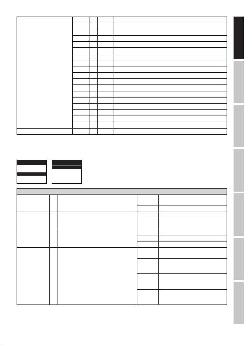
STATIC
Pan 000 - 255 0% to 100%
Pan fine 000 - 255 0% to 100%
Endless Pan 000 - 005 No function
ENGLISH
Tilt 000 - 255 0% to 100%
Tilt fine 000 - 255 0% to 100%
Endless Tilt 000 - 005 No function
DEUTSCHFRANCAIS
Dimmer 000 - 255 0% to 100%
Strobe 000 - 005 Strobe open
Red 000 - 255 0% to 100%
Green 000 - 255 0% to 100%
Blue 000 - 255 0% to 100%
ESPAÑOL
White 000 - 255 0% to 100%
Device settings 000 - 005 no function
006 - 126 Forward rotation fast -> slow
127 - 128 Stop
129 - 255 Backward rotation slow -> fast
006 - 126 Forward rotation fast -> slow
127 - 128 Stop
129 - 255 Backward rotation slow -> fast
006 - 010 Strobe closed
011 - 033 Pulse Random, slow -> fast
034 - 056 Ramp up Random, slow -> fast
057 - 079 Ramp down Random, slow -> fast
080 - 102 Random Strobe Effect, slow -> fast
103 - 127 Strobe Break Effect, 5s…..1s (Short burst with break)
128 - 250 Strobe slow -> fast <1 Hz - 20 Hz
251 - 255 Strobe open
006 - 032 Blackout while Moving on
033 - 059 Blackout while Moving off
060 - 086 Invert Pan on
087 - 113 Invert Pan off
114 - 140 Invert Tilt on
141 - 167 Invert Tilt off
168 - 194 Silent Fan on
195 - 221 Silent Fan off
222 - 255 Reset All Functions
ITALIANO POLSKI
DMX
8
Colour Ring Macro 000 - 005 Colour off
006 - 013 Colour Macro 1 (Colour Jump)
014 - 021 Colour Macro 2 (Red 1 Step)
022 - 029 Colour Macro 3 (Green 1 Step)
030 - 037 Colour Macro 4 (Blue 1 Step)
038 - 045 Colour Macro 5 (Yellow 1 Step)
046 - 053 Colour Macro 6 (Cyan 1 Step)
054 - 061 Colour Macro 7 (Magenta 1 Step)
062 - 069 Colour Macro 8 (2step Magenta Yellow)
070 - 077 Colour Macro 9 (2step Red Green)
078 - 085 Colour Macro 10 (2step Red Blue)
086 - 093 Colour Macro 11 (2step Blue Yellow)
094 - 101 Colour Macro 12 (2step Green Blue)
102 - 109 Colour Macro 13 (2step Magenta Blue)
110 - 117 Colour Macro 14 (2step Green Yellow)
118 - 125 Colour Macro 15 (2step Cyan Magenta)
126 - 133 Colour Macro 16 (2step Cyan Red)
134 - 255 No function
Colour Ring Macro Speed 000 - 255 slow -> fast
DEVICE SETTINGS (Setting)
Pressing MODE will take you to the selection menu for system settings. Using UP and DOWN, select the menu item "Setting" (coloured background)
and confirm with ENTER. You will then be taken to the sub-menu to set the sub-menu items (see list). The main display is automatically activated if
no input is made within about 30 seconds.
DMX 35 Ch
ADDRESS 001
MODE xxx
Setting
System Info
DMX 35 Ch
Display Rev xxx
|
|
|
Reset
FRANCAISDEUTSCHENGLISH
Setting
Display Rev = Flip Display ON = Rotation of the display by 180°
(e.g. overhead installation)
OFF = no rotation of the display
Display = Display lighting ON = permanently on
OFF = deactivation after approx. 1 minutes of
inactivity
DMX Fail = Operation status with DMX signal interruption Hold = last command is held
Blackout = activates Blackout
Auto = activates the AUTO mode
Dimmer Curve = Dimmer Curve Linear = The light intensity increases linearly with
the DMX value.
Exp = Adjustment of the light intensity is finer
in the lower DMX value range and coarser
in the upper DMX value range.
Log = Adjustment of the light intensity is
coarser in the lower DMX value range and
finer in the upper DMX value range.
S Curve = Adjustment of the light intensity is finer in
the lower and upper DMX value ranges and
coarser in the middle DMX value range.
ITALIANOPOLSKIESPAÑOL
DMX
9

Pan Rev = Pan Reverse Normal = no reversal of the Pan direction
Reverse = Reversal of the Pan direction
Tilt Rev = Tilt Reverse Normal = no reversal of the Tilt direction
Reverse = Reversal of the Tilt direction
Feedback = position correction ON = activates automatic position correction
ENGLISH
Fan Control = Fan Speed Regular = maximum brightness at normal fan function
Mov Blackout = Automatic blackout during head movement ON = Blackout during head movement
Calibrate = Correction of the head position of Pan and Tilt Pan Position correction value -128 to +127
DEUTSCHFRANCAIS
TEST = Function test OFF = stops the function test
Reset = Reset Pan&Tilt = Resetting of the Pan & Tilt motors
OFF = deactivates automatic position correction
Silent = if necessary, reduced brightness with
silent fan
OFF = no blackout during head movement
Tilt Position correction value -128 to +127
ON = step-by-step function test of LEDs and
motors (approx. 30 seconds)
All = Resetting all motors and settings
DIMMER CURVES
linear exponential logarithmic S-curve
Light intensity
DMX value
ESPAÑOL
DEVICE INFORMATION (System Info)
Pressing MODE will take you to the selection menu for system settings. Using UP and DOWN, select the menu item "System Info" (coloured
background) and confirm with ENTER. You will then be taken to the sub-menu to display the device information. Use the UP and DOWN panels
again to select the desired sub-menu item and then press ENTER to retrieve the information.
DMX 35 Ch
ADDRESS 001
MODE xxx
Setting
System Info
System Info
Software Ver = Displays the device software version VR. xx
Temp info = Temperature display of the LED unit LED Temp xxC / xxF
Time info = Operating time display Power on Displays the total operating time in hours
ITALIANO POLSKI
Press the MODE button repeatedly to return to the main display. The main display is automatically activated if no input is made within about
30 seconds.
Light intensity
DMX value DMX value DMX value
DMX 35 Ch
Software Ver VR.xx
Temp info
Time info
Light intensity
Temp Unit Celsius (= display in degrees Celsius)
Last Run Hrs Displays the operating time since the last operation
Light intensity
Fahrenheit (= display in degrees Fahrenheit)
DMX
10

SETTING UP AND MOUNTING
Thanks to the integrated rubber feet, the spotlight can be placed in a suitable location on the stage floor etc. Mounting on a truss is
performed using the supplied omega bracket (use only the original mounting bracket); secure the device with a suitable safety rope to the
location (A). Important Notice: Overhead installation should only be carried out by trained personnel.
A
FRANCAISDEUTSCHENGLISH
ITALIANOPOLSKIESPAÑOL
11
DMX
DMX TECHNOLOGY
DMX-512
DMX (Digital Multiplex) is the designation for a universal transmission protocol for communications
between corresponding devices and controllers. A DMX controller sends DMX data to the connected
DMX device(s). The DMX data is always transmitted as a serial data stream that is forwarded from
ENGLISH
one connected device to the next via the "DMX IN" and "DMX OUT" connectors (XLR plug-type
connectors) that are found on every DMX-capable device, provided the maximum number of devices
does not exceed 32 units. The last device in the chain needs to be equipped with a terminator
(terminating resistor).
DMX CONNECTION
DMX is the common "language" via which a very wide range of types and models of equipment from various manufacturers can
be connected with one another and controlled via a central controller, provided that all of the devices and the controller are DMX
compatible. For optimum data transmission, it is necessary to keep the connecting cables between the individual devices as short as
possible. The order in which the devices are integrated in the DMX network has no influence on the addresses. Thus the device with
DEUTSCHFRANCAIS
the DMX address 1 can be located at any position in the (serial) DMX chain: at the beginning, at the end or somewhere in the middle.
If the DMX address 1 is assigned to a device, the controller "knows" that it should send all data allocated to address 1 to this device
regardless of its position in the DMX network.
SERIAL CONNECTION OF MULTIPLE LIGHTS
1. Connect the male XLR connector (3-pin or 5-pin) of the DMX cable to the DMX output (female XLR socket) of the first DMX device
(e.g. DMX-Controller).
2. Connect the female 3-pin XLR connector of the DMX cable connected to the first projector to the DMX input (male 3-pin socket)
of the next DMX device. In the same way, connect the DMX output of this device to the DMX input of the next device and repeat until
all devices have been connected. Please note that as a rule, DMX devices are connected in series and connections cannot be shared
without active splitters. The maximum number of DMX devices in a DMX chain should not exceed 32 units.
The Adam Hall 3 STAR, 4 STAR, and 5 STAR product ranges include an extensive selection of suitable cables.
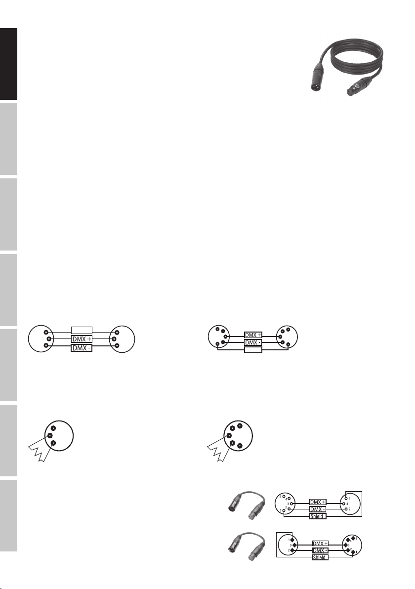
DMX CABLES
When fabricating your own cables, always observe the illustrations on this page. Never connect the shielding of the cable to the ground
contact of the plug, and always make certain that the shielding does not come into contact with the housing of the XLR plug. If the shielding
is connected to the ground, this can lead to short-circuiting and system malfunctions.
ESPAÑOL
Pin Assignment
DMX cable with 3-pin XLR connectors: DMX cable with 5-pin XLR connectors (pin 4 and 5 are not used):
1
3
2
Shield
1
3
2
5
4
3
2
1
Shield
5
4
3
2
1
DMX TERMINATORS (TERMINATING RESISTORS)
To prevent system errors, the last device in a DMX chain needs to be equipped with a terminating resistor (120 ohm, 1/4 Watt).
3-pin XLR connector with a terminating resistor: K3DMXT3
5-pin XLR connector with a terminating resistor: K3DMXT5
Pin Assignment
3-pin XLR connector: 5-pin XLR connector:
1
3
2
5
4
3
2
1
ITALIANO POLSKI
DMX ADAPTER
The combination of DMX devices with 3-pin connectors and DMX devices with 5-pin connectors in a DMX chain is possible with suitable
adapters.
Pin Assignment
DMX Adapter 5-pin XLR male to 3-pin XLR female: K3DGF0020
Pins 4 and 5 are not used.
DMX
Pin Assignment
DMX Adapter 3-pin XLR male to 5-pin XLR female: K3DHM0020
Pins 4 and 5 are not used.
12

TECHNICAL SPECIFICATIONS
Model Name: CLMB100
Product Type: LED moving light
Type: moving head
Colour Spectrum: RGBW
Number of LEDs: 1
LED Type: 60 W COB
Refresh Rate: 3000 Hz
Beam Angle: Beam 5.5°, Field 8.5°
LED Colour Ring: 4 RGB segments
DMX Input: 3-pin XLR male
DMX Output: 3-pin XLR female
DMX Mode: 4-channel, 15-channel, 35-channel
DMX Functions: Pan/Tilt, Pan/Tilt fine, continuous Pan/Tilt, Auto programs, Strobe, RGBW, Colour Ring
Standalone Functions: Pan/Tilt, Pan/Tilt fine, continuous Pan/Tilt, Auto programs, Strobe, Static Mode,
Master/Slave Mode, Colour Ring
PAN Angle: continuous
TILT Angle: continuous
Controllers: Mode, Enter, Up, Down
Indicators: backlit graphic display
Operating Voltage: 100 - 240 V AC / 50 - 60 Hz
Power Consumption: 130 W
Illuminance (@ 1 m): 157,700 lx
Light Output: 1480 lm
Power Connector: blue power input socket
white power output socket
Fuse: T2AL / 250 V (5 x 20 mm)
Temperature (during operation): 5°C to 40°C
Relative Humidity: < 80% non-condensing
Housing Material: metal, ABS
Housing Colour: black
Housing Cooling: fan
Dimensions (W x H x D, excluding bracket): 210 x 325 x 165 mm
Weight: 6.5 kg
Other Features: 1 m power cable with blue plug
and omega mounting bracket included
FRANCAISDEUTSCHENGLISH
MANUFACTURER´S DECLARATIONS
MANUFACTURER‘S WARRANTY & LIMITATIONS OF LIABILITY
You can find our current warranty conditions and limitations of liability at: http://www.adamhall.com/media/shop/downloads/documents/
manufacturersdeclarations.pdf. To request warranty service for a product, please contact Adam Hall GmbH, Daimler Straße 9, 61267 Neu
Anspach / Email: Info@adamhall.com / +49 (0)6081 / 9419-0. To enquire about the current declaration of conformity, please contact
info@adamhall.com.
CORRECT DISPOSAL OF THIS PRODUCT
(Valid in the European Union and other European countries with a differentiated waste collection system) This symbol on the product,
or on its documents indicates that the device may not be treated as household waste. This is to avoid environmental damage or
personal injury due to uncontrolled waste disposal. Please dispose of this product separately from other waste and have it recycled to
promote sustainable economic activity. Household users should contact either the retailer where they purchased this product, or their local
government office, for details on where and how they can recycle this item in an environmentally friendly manner. Business users should
contact their supplier and check the terms and conditions of the purchase contract. This product should not be mixed with other commercial
waste for disposal.
ITALIANOPOLSKIESPAÑOL
DMX
13

DEUTSCH
Sie haben die richtige Wahl getroffen!
Dieses Gerät wurde unter hohen Qualitätsanforderungen entwickelt und gefertigt, um viele Jahre einen reibungslosen Betrieb zu gewährleisten.
Bitte lesen Sie diese Bedienungsanleitung sorgfältig, damit Sie Ihr neues Produkt von Cameo Light schnell und optimal einsetzen können.
Weitere Informationen über Cameo Light erhalten Sie auf unserer Website WWW.CAMEOLIGHT.COM.
ENGLISH
SICHERHEITSHINWEISE
1. Lesen Sie diese Anleitung bitte sorgfältig durch.
2. Bewahren Sie alle Informationen und Anleitungen an einem sicheren Ort auf.
3. Befolgen Sie die Anweisungen.
4. Beachten Sie alle Warnhinweise. Entfernen Sie keine Sicherheitshinweise oder andere Informationen vom Gerät.
5. Verwenden Sie das Gerät nur in der vorgesehenen Art und Weise.
6. Verwenden Sie ausschließlich stabile und passende Stative bzw. Befestigungen (bei Festinstallationen). Stellen Sie sicher, dass Wandhalterungen ordnungsgemäß installiert und gesichert sind. Stellen Sie sicher, dass das Gerät sicher installiert ist und nicht herunterfallen kann.
7. Beachten Sie bei der Installation die für Ihr Land geltenden Sicherheitsvorschriften.
DEUTSCHFRANCAIS
8. Installieren und betreiben Sie das Gerät nicht in der Nähe von Heizkörpern, Wärmespeichern, Öfen oder sonstigen Wärmequellen. Sorgen
Sie dafür, dass das Gerät immer so installiert ist, dass es ausreichend gekühlt wird und nicht überhitzen kann.
9. Platzieren Sie keine Zündquellen wie z.B. brennende Kerzen auf dem Gerät.
10. Lüftungsschlitze dürfen nicht blockiert werden.
11. Das Gerät wurde ausschließlich für die Verwendung in Innenräumen entwickelt, betreiben Sie das Gerät nicht in unmittelbarer Nähe von
Wasser (gilt nicht für spezielle Outdoor Geräte - beachten Sie in diesem Fall bitte die im Folgenden vermerkten Sonderhinweise). Bringen Sie
das Gerät nicht mit brennbaren Materialien, Flüssigkeiten oder Gasen in Berührung.
12. Sorgen Sie dafür, dass kein Tropf- oder Spritzwasser in das Gerät eindringen kann. Stellen Sie keine mit Flüssigkeit gefüllten Behältnisse
wie Vasen oder Trinkgefäße auf das Gerät.
13. Sorgen Sie dafür, dass keine Gegenstände in das Gerät fallen können.
14. Betreiben Sie das Gerät nur mit dem vom Hersteller empfohlenen und vorgesehenen Zubehör.
15. Öffnen Sie das Gerät nicht und verändern Sie es nicht.
16. Überprüfen Sie nach dem Anschluss des Geräts alle Kabelwege, um Schäden oder Unfälle, z. B. durch Stolperfallen zu vermeiden.
17. Achten Sie beim Transport darauf, dass das Gerät nicht herunterfallen und dabei möglicherweise Sach- und Personenschäden verursachen kann.
18. Wenn Ihr Gerät nicht mehr ordnungsgemäß funktioniert, Flüssigkeiten oder Gegenstände in das Geräteinnere gelangt sind, oder das Gerät
anderweitig beschädigt wurde, schalten Sie es sofort aus und trennen es von der Netzsteckdose (sofern es sich um ein aktives Gerät handelt).
Dieses Gerät darf nur von autorisiertem Fachpersonal repariert werden.
19. Verwenden Sie zur Reinigung des Geräts ein trockenes Tuch.
20. Beachten Sie alle in Ihrem Land geltenden Entsorgungsgesetze. Trennen Sie bei der Entsorgung der Verpackung bitte Kunststoff und
ESPAÑOL
Papier bzw. Kartonagen voneinander.
21. Kunststoffbeutel müssen außer Reichweite von Kindern aufbewahrt werden.
BEI GERÄTEN MIT NETZANSCHLUSS:
22. ACHTUNG: Wenn das Netzkabel des Geräts mit einem Schutzkontakt ausgestattet ist, muss es an einer Steckdose mit Schutzleiter
angeschlossen werden. Deaktivieren Sie niemals den Schutzleiter eines Netzkabels.
23. Schalten Sie das Gerät nicht sofort ein, wenn es starken Temperaturschwankungen ausgesetzt war (beispielsweise nach dem Transport).
Feuchtigkeit und Kondensat könnten das Gerät beschädigen. Schalten Sie das Gerät erst ein, wenn es Zimmertemperatur erreicht hat.
24. Bevor Sie das Gerät an die Steckdose anschließen, prüfen Sie zuerst, ob die Spannung und die Frequenz des Stromnetzes mit den auf
dem Gerät angegebenen Werten übereinstimmen. Verfügt das Gerät über einen Spannungswahlschalter, schließen Sie das Gerät nur an die
Steckdose an, wenn die Gerätewerte mit den Werten des Stromnetzes übereinstimmen. Wenn das mitgelieferte Netzkabel bzw. der mitgelieferte Netzadapter nicht in Ihre Netzsteckdose passt, wenden Sie sich an Ihren Elektriker.
25. Treten Sie nicht auf das Netzkabel. Sorgen Sie dafür, dass spannungsführende Kabel speziell an der Netzbuchse bzw. am Netzadapter
und der Gerätebuchse nicht geknickt werden.
26. Achten Sie bei der Verkabelung des Geräts immer darauf, dass das Netzkabel bzw. der Netzadapter stets frei zugänglich ist. Trennen Sie
das Gerät stets von der Stromzuführung, wenn das Gerät nicht benutzt wird, oder Sie das Gerät reinigen möchten. Ziehen Sie Netzkabel und
Netzadapter immer am Stecker bzw. am Adapter und nicht am Kabel aus der Steckdose. Berühren Sie Netzkabel und Netzadapter niemals
mit nassen Händen.
27. Schalten Sie das Gerät möglichst nicht schnell hintereinander ein und aus, da sonst die Lebensdauer des Geräts beeinträchtigt werden könnte.
ITALIANO POLSKI
28. WICHTIGER HINWEIS: Ersetzen Sie Sicherungen ausschließlich durch Sicherungen des gleichen Typs und Wertes. Sollte eine Sicherung
wiederholt auslösen, wenden Sie sich bitte an ein autorisiertes Servicezentrum.
29. Um das Gerät vollständig vom Stromnetz zu trennen, entfernen Sie das Netzkabel bzw. den Netzadapter aus der Steckdose.
30. Wenn Ihr Gerät mit einem Volex-Netzanschluss bestückt ist, muss der passende Volex-Gerätestecker entsperrt werden, bevor er entfernt
werden kann. Das bedeutet aber auch, dass das Gerät durch ein Ziehen am Netzkabel verrutschen und herunterfallen kann, wodurch Personen verletzt werden und/oder andere Schäden auftreten können. Verlegen Sie Ihre Kabel daher immer sorgfältig.
31. Entfernen Sie Netzkabel und Netzadapter aus der Steckdose bei Gefahr eines Blitzschlags oder wenn Sie das Gerät länger nicht verwenden.
32. Das Gerät darf nur im spannungsfreien Zustand (Trennung des Netzsteckers vom Stromnetz) installiert werden.
DMX
33. Staub und andere Ablagerungen im Inneren des Geräts können es beschädigen. Das Gerät sollte je nach Umgebungsbedingungen
(Staub, Nikotin, Nebel etc.) regelmäßig von qualifiziertem Fachpersonal gewartet bzw. gesäubert werden (keine Garantieleistung),
um Überhitzung und Fehlfunktionen zu vermeiden.
34. Der Abstand zu brennbaren Materialien muss mindestens 0,5 m betragen.
14

35. Netzleitungen zur Spannungsversorgung mehrerer Geräte müssen mindestens 1,5 mm² Aderquerschnitt aufweisen. In der EU müssen
die Leitungen H05VV-F, oder gleichartig, entsprechen. Geeignete Leitungen werden von Adam Hall angeboten. Mit diesen Leitungen können
Sie mehrere Geräte über den Power out Anschluss mit dem Power IN Anschluss eines weiteren Gerätes verbinden. Beachten Sie, dass die
gesamte Stromaufnahme aller angeschlossenen Geräte den vorgegebenen Wert nicht überschreitet (Aufdruck auf dem Gerät). Achten Sie
darauf, Netzleitungen so kurz wie möglich zu halten.
ACHTUNG
Entfernen Sie niemals die Abdeckung, da sonst das Risiko eines elektrischen Schlages besteht. Im
Inneren des Geräts befinden sich keine Teile, die vom Bediener repariert oder gewartet werden können.
Lassen Sie Wartung und Reparaturen ausschließlich von qualifiziertem Servicepersonal durchführen.
Das gleichseitige Dreieck mit Blitzsymbol warnt vor nichtisolierten, gefährlichen Spannungen im Geräteinneren, die einen
elektrischen Schlag verursachen können.
Das gleichseitige Dreieck mit Ausrufungszeichen kennzeichnet wichtige Bedienungs- und Wartungshinweise.
Warnung! Dieses Symbol kennzeichnet heiße Oberflächen. Während des Betriebs können bestimmte Teile des Gehäuses heiß
werden. Berühren oder transportieren Sie das Gerät nach einem Einsatz erst nach einer Abkühlzeit von mindestens 10 Minuten.
ACHTUNG HOHE LAUTSTÄRKEN BEI AUDIOPRODUKTEN!
Dieses Gerät ist für den professionellen Einsatz vorgesehen. Der kommerzielle Betrieb dieses Geräts unterliegt den jeweils gültigen nationalen
Vorschriften und Richtlinien zur Unfallverhütung. Als Hersteller ist Adam Hall gesetzlich verpflichtet, Sie ausdrücklich auf mögliche Gesundheitsrisiken
hinzuweisen. Gehörschäden durch hohe Lautstärken und Dauerbelastung: Bei der Verwendung dieses Produkts können hohe Schalldruckpegel (SPL)
erzeugt werden, die bei Künstlern, Mitarbeitern und Zuschauern zu irreparablen Gehörschäden führen können. Vermeiden Sie länger anhaltende
Belastung durch hohe Lautstärken über 90 dB.
VORSICHT! WICHTIGE HINWEISE IN BEZUG AUF LICHT-PRODUKTE!
1. Das Produkt ist für den professionellen Einsatz im Bereich der Veranstaltungstechnik entwickelt worden und ist nicht für die Raumbeleuchtung
in Haushalten geeignet.
2. Blicken Sie niemals, auch nicht kurzzeitig, direkt in den Lichtstrahl.
3. Blicken Sie niemals mit optischen Geräten wie Vergrößerungsgläsern in den Lichtstrahl.
4. Stoboskopeffekte können unter Umständen bei empfindlichen Menschen epileptische Anfälle auslösen! Epilepsiekranke Menschen sollten
daher unbedingt Orte meiden, an denen Stroboskope eingesetzt werden.
FRANCAISDEUTSCHENGLISH
EINFÜHRUNG
Der Cameo MovoBeam 100 ist ein ultraschneller Moving Head mit unbegrenzter Pan- und Tilt-Bewegung, 16-Bit-Auflösung und 3.000 Hz
Wiederholrate. Eine 60 Watt starke COB Quad-LED erzeugt satte RGBW-Farben, frische Pastelltöne und lebendige Weißabstufungen mit Beam
5,5° und Field 8,5° Abstrahlwinkel und einer Beleuchtungsstärke von 157700 Lux.
STEUERUNGSFUNKTIONEN:
4-Kanal, 15-Kanal, 35-Kanal DMX-Steuerung
Master / Slave Betrieb
Standalone Funktionen
EIGENSCHAFTEN:
1 x High Power 60W COB RGBW LED, RGBW Farbmischung, 6° Abstrahlwinkel, 2 High Speed Motoren für Pan und Tilt, endlose Pan- und
Tilt-Bewegung, Geeignet für TV und Video durch 3.000 Hz Wiederholrate, DMX-512 Steuerung, Master / Slave Betrieb, Standalone Programme,
Betriebsspannung 100V - 240V AC / 50 - 60Hz, Leistungsaufnahme 130W, Omega-Montagebügel inklusive.
ITALIANOPOLSKIESPAÑOL
DMX
15

ANSCHLÜSSE, BEDIEN- UND ANZEIGEELEMENTE
ENGLISH
3
DEUTSCHFRANCAIS
POWER IN
1
Blaue Netzeingangsbuchse. Betriebsspannung 100 - 240V AC / 50 - 60Hz. Anschluss über das mitgelieferte Netzkabel.
POWER OUT
2
Weiße Netzausgangsbuchse. Dient der Netzversorgung weiterer CAMEO Scheinwerfer. Achten Sie darauf, dass die gesamte Stromaufnahme
aller angeschlossenen Geräte den auf dem Gerät in Ampere (A) angegebenen Wert nicht überschreitet.
DMX IN
3
Männliche 3-Pol XLR-Buchse zum Anschließen eines DMX-Kontrollgeräts (z.B. DMX-Pult).
4
DMX OUT
Weibliche 3-Pol XLR-Buchse zum Weiterleiten des DMX-Steuersignals.
1
2
4
ESPAÑOL
5
6
5
BELEUCHTETES GRAFIK-DISPLAY
Zeigt den Betriebsmodus und weitere Systemeinstellungen an.
6
BEDIENTASTEN
MODE
ITALIANO POLSKI
Durch Drücken auf MODE gelangen Sie in das Auswahl-Menü für die Systemeinstellungen. Durch wiederholtes Drücken gelangen Sie
zurück zur Hauptanzeige.
UP und DOWN
Auswählen der einzelnen Menü-Punkte im Auswahl-Menü für die Systemeinstellungen (DMX-Adresse, Betriebsart usw.) und den Untermenüs.
Diese Bedienfelder ermöglichen es, den Wert eines Menü-Punkts, wie z.B. die DMX-Adresse, wunschgemäß zu verändern.
DMX
ENTER
Durch Drücken auf ENTER gelangen Sie im Auswahl-Menü auf die Untermenüs, um dort Wertänderungen vornehmen zu können. Wertände-
rungen bestätigen Sie ebenfalls durch Drücken auf ENTER.
16

BEDIENUNG
HINWEIS
Sobald der Scheinwerfer korrekt am Stromnetz angeschlossen ist, werden während des Startvorgangs und des Motoren-Resets „Welcome
to Cameo“ und die Softwareversion im Display angezeigt. Nach diesem Vorgang ist der Scheinwerfer betriebsbereit und die Betriebsart, die
zuvor angewählt war, wird aktiviert.
HAUPTANZEIGE DMX BETRIEBSART
In der oberen Zeile des Displays wird der DMX Modus (DMX 4 Ch, 15 Ch, 35 Ch) und gut sichtbar in der Mitte die DMX-Startadresse
angezeigt (im Beispiel DMX 35 Ch und ADDRESS 001). Sobald das DMX-Signal unterbrochen wird, fängt das Display an zu blinken, liegt das
DMX-Signal wieder an, stoppt das Blinken.
DMX 35Ch
ADDRESS
001
HAUPTANZEIGE SLAVE BETRIEBSART
In der oberen Zeile des Displays wird der voreingestellte DMX-Modus und gut sichtbar in der Mitte „SLAVE“ angezeigt. Sobald das Steuer-Signal
unterbrochen wird, fängt das Display an zu blinken, liegt das Signal wieder an, stoppt das Blinken.
DMX 35Ch
Operating Mode
SLAVE
HAUPTANZEIGE STANDALONE BETRIEBSART
In der oberen Zeile des Displays wird der voreingestellte DMX-Modus und gut sichtbar in der Mitte die aktuell aktivierte Auto-Betriebsart
(AUTO1 - AUTO8), bzw. der statische Modus STATIC angezeigt.
DMX 35Ch
Operating Mode
AUTO1
DMX-STARTADRESSE EINSTELLEN (ADDRESS)
Durch Drücken auf MODE gelangen Sie in das Auswahl-Menü für die Systemeinstellungen. Mit Hilfe der Bedienfelder UP und DOWN wählen
Sie nun den Menü-Punkt „ADDRESS“ aus (farbig hinterlegt) und bestätigen mit ENTER. Darauf folgt die Anzeige des Untermenüpunkts „Set
DMX Address“. Drücken Sie abermals auf ENTER, um die DMX Startadresse wunschgemäß mit Hilfe von UP und DOWN einzustellen. Wird
die Startadresse verändert, wechselt die Farbe der Adresse auf Rot. Bestätigen Sie die Eingabe mit ENTER und drücken 2x auf MODE, um zur
Hauptanzeige zurückzugelangen. Die Hauptanzeige wird automatisch aktiviert, wenn innerhalb von circa 30 Sekunden keine Eingabe erfolgt.
DMX 35 Ch
ADDRESS 001
MODE DMX 35CH
Settings
System Info
DMX 35Ch
Operating Mode
STATIC
DMX 35 Ch
Set DMX Address 001
DMX 35 Ch
Set DMX Address
001
< >
FRANCAISDEUTSCHENGLISH
DMX BETRIEBSART EINSTELLEN (DMX Mode)
Durch Drücken auf MODE gelangen Sie in das Auswahl-Menü für die Systemeinstellungen. Mit Hilfe der Bedienfelder UP und DOWN wählen
Sie nun den Menü-Punkt „MODE“ aus (farbig hinterlegt) und bestätigen mit ENTER. Wählen Sie wiederum mit Hilfe von UP und DOWN den
Untermenüpunkt „DMX Mode“ aus und bestätigen mit ENTER. Nun können Sie den gewünschten DMX-Modus mit Hilfe von UP und DOWN
auswählen (DMX 4 Ch, DMX 15 Ch, DMX 35 Ch) und die Auswahl mit ENTER bestätigen. Drücken Sie 2x auf MODE, um zur Hauptanzeige
zurückzugelangen. Die Hauptanzeige wird automatisch aktiviert, wenn innerhalb von circa 30 Sekunden keine Eingabe erfolgt. Tabellen mit
der Kanalbelegung der verschiedenen DMX-Modi finden Sie in dieser Anleitung unter DMX-STEUERUNG.
DMX 35 Ch
ADDRESS 001
MODE DMX 35CH
Setting
System Info
DMX 35 Ch
DMX Mode Yes
Slave
Auto
Static
DMX 35 Ch
DMX 4 Ch
DMX 15 Ch
DMX 35 Ch Yes
ITALIANOPOLSKIESPAÑOL
DMX
17

SLAVE BETRIEBSART EINSTELLEN (Slave)
Durch Drücken auf MODE gelangen Sie in das Auswahl-Menü für die Systemeinstellungen. Mit Hilfe der Bedienfelder UP und DOWN wählen
Sie nun den Menü-Punkt „MODE“ aus (farbig hinterlegt) und bestätigen mit ENTER. Wählen Sie wiederum mit Hilfe von UP und DOWN den
Untermenüpunkt „Slave“ aus, bestätigen mit ENTER und drücken 2x auf MODE, um zur Hauptanzeige zurückzugelangen. Die Hauptanzeige
wird automatisch aktiviert, wenn innerhalb von circa 30 Sekunden keine Eingabe erfolgt. Verbinden Sie die Slave- und die Master-Einheit
(gleiches Modell) mit Hilfe eines DMX-Kabels und aktivieren Sie in der Master-Einheit eine der Standalone Betriebsarten (Auto, Static). Nun
ENGLISH
folgt die Slave-Einheit der Master-Einheit.
DMX 35 Ch
ADDRESS 001
MODE DMX 35CH
Setting
System Info
DMX 35 Ch
DMX Mode
Slave Yes
Auto
Static
BETRIEBSART AUTOMATISCHE STEUERUNG EINSTELLEN (Auto)
Durch Drücken auf MODE gelangen Sie in das Auswahl-Menü für die Systemeinstellungen. Mit Hilfe der Bedienfelder UP und DOWN
DEUTSCHFRANCAIS
wählen Sie nun den Menü-Punkt „MODE“ aus (farbig hinterlegt) und bestätigen mit ENTER. Wählen Sie wiederum mit Hilfe von UP und
DOWN den Untermenüpunkt „Auto“ aus und bestätigen mit ENTER. Mit Hilfe von UP und DOWN können Sie nun zwischen zwei weiteren
Untermenüpunkten wählen, „Auto Prog“ und „Auto Speed“. Wählen Sie „Auto Prog“, drücken auf ENTER, wählen eines der 8 verschiedenen
Auto-Programme (Prog1 - Prog8) aus und bestätigen mit ENTER. Die Programm-Laufgeschwindigkeit stellen Sie ein, indem Sie nun mit Hilfe
von UP und DOWN „Auto Speed“ anwählen, auf ENTER drücken und erneut mit Hilfe von UP und DOWN die gewünschte Geschwindigkeit
von 000 bis 255 einstellen (000 = schnellste Laufgeschwindigkeit, 255 = langsamste Laufgeschwindigkeit). Bestätigen Sie mit ENTER und
drücken 3x auf MODE, um zur Hauptanzeige zurückzugelangen. Die Hauptanzeige wird automatisch aktiviert, wenn innerhalb von circa 30
Sekunden keine Eingabe erfolgt.
DMX 35 Ch
ADDRESS 001
MODE xxx
Setting
System Info
ESPAÑOL
DMX 35 Ch
DMX Mode
Slave
Auto
Static
DMX 35 Ch
Auto Progx
Auto Speed xxx
DMX 35 Ch
Auto Progx
Auto Speed xxx
DMX 35 Ch
Prog1 Yes
|
|
|
Prog8
DMX 35 Ch
Auto Speed
< >
000
STATISCHER MODUS (Static)
Der statische Modus ermöglicht es, ähnlich wie mit einem DMX-Steuergerät, alle Funktionen, wie z.B. Pan, Tilt, Dimmer und Stroboskop,
direkt am Gerät mit Werten von 000 bis 255 einstellen zu können. Somit kann eine individuelle Szene erstellt werden, ohne einen
zusätzlichen DMX-Controller zu benötigen. Durch Drücken auf MODE gelangen Sie in das Auswahl-Menü für die Systemeinstellungen. Mit
Hilfe der Bedienfelder UP und DOWN wählen Sie nun den Menü-Punkt „Static“ aus (farbig hinterlegt) und bestätigen mit ENTER. Wählen Sie
die Funktion des Moving Heads mit Hilfe von UP und DOWN an, deren Wert Sie wunschgemäß editieren möchten und bestätigen mit ENTER.
Der Wert (Pan Position, Dimmer etc., siehe Liste) der entsprechenden Funktion kann nun von 000 bis 255 eingestellt und die Eingabe mit
ENTER bestätigt werden. Nachdem alle Funktionen wunschgemäß eingestellt wurden, drücken Sie 3x auf MODE, um zurück zur
Hauptanzeige zu gelangen. Die Hauptanzeige wird automatisch aktiviert, wenn innerhalb von circa 30 Sekunden keine Eingabe erfolgt.
DMX 35 Ch
ADDRESS 001
MODE xxx
Setting
System Info
DMX 35 Ch
DMX Mode
Slave
Auto
Static
DMX 35 Ch
Pan xxx
|
|
|
Ring Macro Speed xxx
DMX 35 Ch
Pan
< >
000
ITALIANO POLSKI
DMX
18

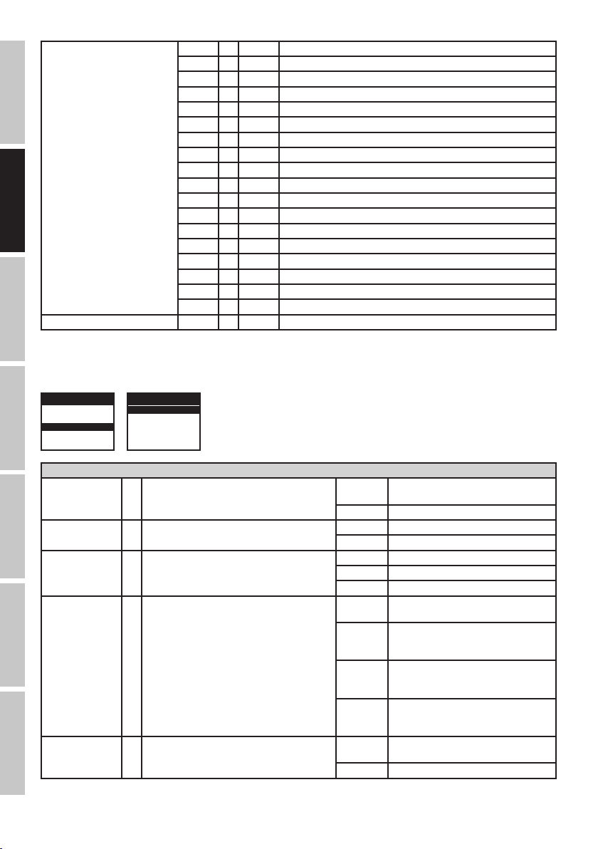
STATIC
Pan 000 - 255 0% to 100%
Pan fine 000 - 255 0% to 100%
Endless Pan 000 - 005 No function
006 - 126 Forward rotation fast -> slow
127 - 128 Stop
129 - 255 Backward rotation slow -> fast
Tilt 000 - 255 0% to 100%
Tilt fine 000 - 255 0% to 100%
Endless Tilt 000 - 005 No function
006 - 126 Forward rotation fast -> slow
127 - 128 Stop
129 - 255 Backward rotation slow -> fast
Dimmer 000 - 255 0% to 100%
Strobe 000 - 005 Strobe open
006 - 010 Strobe closed
011 - 033 Puls Random, slow -> fast
034 - 056 Ramp up Random, slow -> fast
057 - 079 Ramp down Random, slow -> fast
080 - 102 Random Strobe Effect, slow -> fast
103 - 127 Strobe Break Effekt, 5s…..1s (Short burst with break)
128 - 250 Strobe slow -> fast <1Hz - 20Hz
251 - 255 Strobe open
Red 000 - 255 0% to 100%
Green 000 - 255 0% to 100%
Blue 000 - 255 0% to 100%
White 000 - 255 0% to 100%
Device settings 000 - 005 no function
006 - 032 Blackout while Moving on
033 - 059 Blackout while Moving off
060 - 086 Invert Pan on
087 - 113 Invert Pan off
114 - 140 Invert Tilt on
141 - 167 Invert Tilt off
168 - 194 Silent Fan on
195 - 221 Silent Fan off
222 - 255 Reset All Functions
FRANCAISDEUTSCHENGLISH
ITALIANOPOLSKIESPAÑOL
19
DMX
Colour Ring Macro 000 - 005 Colour off
006 - 013 Colour Macro 1 (Colour Jump)
014 - 021 Colour Macro 2 (Red 1 Step)
022 - 029 Colour Macro 3 (Green 1 Step)
ENGLISH
030 - 037 Colour Macro 4 (Blue 1 Step)
038 - 045 Colour Macro 5 (Yellow 1 Step)
046 - 053 Colour Macro 6 (Cyan 1 Step)
054 - 061 Colour Macro 7 (Magenta 1 Step)
062 - 069 Colour Macro 8 (2step Magenta Yellow)
070 - 077 Colour Macro 9 (2step Red Green)
078 - 085 Colour Macro 10 (2step Red Blue)
DEUTSCHFRANCAIS
086 - 093 Colour Macro 11 (2step Blue Yellow)
094 - 101 Colour Macro 12 (2step Green Blue)
102 - 109 Colour Macro 13 (2step Magenta Blue)
110 - 117 Colour Macro 14 (2step Green Yellow)
118 - 125 Colour Macro 15 (2step Cyan Magenta)
126 - 133 Colour Macro 16 (2step Cyan Red)
134 - 255 No function
Colour Ring Macro Speed 000 - 255 slow -> fast
GERÄTEEINSTELLUNGEN (Setting)
Durch Drücken auf MODE gelangen Sie in das Auswahl-Menü für die Systemeinstellungen. Mit Hilfe der Bedienfelder UP und DOWN wählen Sie
nun den Menü-Punkt „Setting“ aus (farbig hinterlegt) und bestätigen mit ENTER. Daraufhin gelangen Sie in das Untermenü zum Einstellen der
Untermenü-Punkte (siehe Liste). Die Hauptanzeige wird automatisch aktiviert, wenn innerhalb von circa 30 Sekunden keine Eingabe erfolgt.
ESPAÑOL
DMX 35 Ch
ADDRESS 001
MODE xxx
Setting
System Info
DMX 35 Ch
Display Rev xxx
|
|
|
Reset
Setting
Display Rev = Flip Display ON = Drehung der Display-Anzeige um 180°
(z.B. Überkopfmontage)
OFF = keine Drehung der Display-Anzeige
Display = Display-Beleuchtung ON = permanent an
OFF = Deaktivierung nach ca. 1 Minute Inaktivität
DMX Fail = Betriebszustand bei DMX Signal Unterbrechung Hold = letzter Befehl wird gehalten
Blackout = aktiviert Blackout
Auto = aktiviert Auto-Modus
Dimmer Curve = Dimmerkurve Linear = Die Lichtintensität steigt linear mit dem
DMX-Wert an
Exp = Die Lichtintensität lässt sich im unteren
DMX-Wertbereich fein und im oberen
ITALIANO POLSKI
DMX-Wertbereich grob einstellen
Log = Die Lichtintensität lässt sich im unteren
DMX-Wertbereich grob und im oberen
DMX-Wertbereich fein einstellen
S Curve = Die Lichtintensität lässt sich im unteren
und oberen DMX-Wertbereich fein und im
mittleren DMX-Wertbereich grob einstellen
Pan Rev = Pan Reverse Normal = keine Umkehrung der Pan
DMX
Bewegungsrichtung
Reverse = Umkehrung der Pan Bewegungsrichtung
20

Tilt Rev = Tilt Reverse Normal = keine Umkehrung der Tilt
Bewegungsrichtung
Reverse = Umkehrung der Tilt Bewegungsrichtung
Feedback = Positionskorrektur ON = automatische Positionskorrektur aktiviert
OFF = automatische Positionskorrektur deaktiviert
Fan Control = Lüftergeschwindigkeit Regular = maximale Helligkeit bei normaler
Lüfterfunktion
Silent = falls notwendig, reduzierte Helligkeit bei
leisem Lüfter
Mov Blackout = Automatischer Blackout bei Kopfbewegung ON = Blackout bei Kopfbewegung
OFF = kein Blackout bei Kopfbewegung
Calibrate = Korrektur der Kopfposition Pan und Tilt Pan Positionskorrektur von Wert -128 bis Wert
+127
Tilt Positionskorrektur von Wert -128 bis Wert
+127
TEST = Funktionstest OFF = Stopp des Funktionstests
ON = schrittweiser Funktionstest der LEDs und
der Motoren (ca. 30 Sek.)
Reset = Zurücksetzen Pan&Tilt = Zurücksetzen der Pan & Tilt Motoren
All = Zurücksetzen aller Motoren und
Einstellungen
DIMMERKURVEN
linear exponential logarithmic S-curve
FRANCAISDEUTSCHENGLISH
Light intensity
DMX value
Light intensity
DMX value DMX value DMX value
Light intensity
Light intensity
GERÄTEINFORMATIONEN (System Info)
Durch Drücken auf MODE gelangen Sie in das Auswahl-Menü für die Systemeinstellungen. Mit Hilfe der Bedienfelder UP und DOWN wählen Sie
nun den Menü-Punkt „System Info“ aus (farbig hinterlegt) und bestätigen mit ENTER. Daraufhin gelangen Sie in das Untermenü zum Anzeigen
der Geräteinformationen. Benutzen Sie wiederum die Bedienfelder UP und DOWN, um den gewünschten Untermenüpunkt anzuwählen und die
Information dann mit ENTER abzurufen.
DMX 35 Ch
ADDRESS 001
MODE xxx
Setting
System Info
DMX 35 Ch
Software Ver VR.xx
Temp info
Time info
System Info
Software Ver = Anzeige der Geräte-Softwareversion VR. xx
Temp info = Temperaturanzeige der LED-Einheit LED Temp xxC / xxF
Temp Unit Celsius (= Anzeige in Grad Celsius)
Fahrenheit (= Anzeige in Grad Fahrenheit)
Time info = Betriebsdaueranzeige Power on Anzeige der Gesamtbetriebsdauer in Stunden
Last Run Hrs Anzeige der Betriebsdauer seit dem letzten
Einschalten
Drücken Sie mehrfach die MODE-Taste, um zur Hauptanzeige zurückzugelangen. Die Hauptanzeige wird automatisch aktiviert, wenn innerhalb
von circa 30 Sekunden keine Eingabe erfolgt.
ITALIANOPOLSKIESPAÑOL
DMX
21

AUFSTELLUNG UND MONTAGE
Dank der integrierten Gummifüße kann der Scheinwerfer an einer geeigneten Stelle auf den Bühnenboden etc. gestellt werden.
Die Montage an einer Traverse erfolgt mit Hilfe des mitgelieferten Omega-Bügels (bitte ausschließlich den Original-Montagebügel nutzen),
sichern Sie das Gerät mit einem geeigneten Sicherungsseil an der dafür vorgesehenen Stelle (A). Wichtiger Hinweis: Überkopfmontage darf
nur von dafür ausgebildetem Personal durchgeführt werden.
ENGLISH
DEUTSCHFRANCAIS
A
ESPAÑOL
ITALIANO POLSKI
DMX
22

DMX TECHNIK
DMX-512
DMX (Digital Multiplex) ist die Bezeichnung für ein universelles Übertragungsprotokoll für die
Kommunikation zwischen entsprechenden Geräten und Controllern. Ein DMX-Controller sendet
DMX-Daten an das/die angeschlossene(n) DMX-Gerät(e). Die DMX-Datenübertragung erfolgt stets als
serieller Datenstrom, der über die an jedem DMX-fähigen Gerät vorhandenen DMX IN- und DMX OUTAnschlüsse (XLR-Steckverbinder) von einem angeschlossenen Gerät an das nächste weitergeleitet
wird, wobei die maximale Anzahl der Geräte 32 nicht überschreiten darf. Das letzte Gerät der Kette ist
mit einem Abschlussstecker (Terminator) zu bestücken.
DMX-VERBINDUNG:
DMX ist die gemeinsame "Sprache", über die sich die unterschiedlichsten Gerätetypen und Modelle verschiedener Hersteller
miteinander verkoppeln und über einen zentralen Controller steuern lassen, sofern sämtliche Geräte und der Controller DMXkompatibel sind. Für eine optimale Datenübertragung ist es erforderlich, die Verbindungskabel zwischen den einzelnen Geräten so
kurz wie möglich zu halten. Die Reihenfolge, in der die Geräte in das DMX-Netzwerk eingebunden sind, hat keinen Einfluss auf die
Adressierung. So kann sich das Gerät mit der DMX-Adresse 1 an einer beliebigen Position in der (seriellen) DMX-Kette befinden, am
Anfang, am Ende oder irgendwo in der Mitte. Wird einem Gerät die DMX-Adresse 1 zugewiesen, "weiß" der Controller, dass er alle
der Adresse 1 zugeordneten Daten an dieses Gerät senden soll, ungeachtet seiner Position im DMX-Verbund.
SERIELLE VERKOPPLUNG MEHRERER SCHEINWERFER
1. Verbinden Sie den männlichen XLR-Stecker (3-Pol oder 5-Pol) des DMX-Kabels mit dem DMX-Ausgang (weibliche XLR-Buchse)
des ersten DMX-Geräts (z.B. DMX-Controller).
2. Verbinden Sie den weibliche XLR-Stecker des an den ersten Scheinwerfer angeschlossenen DMX-Kabels mit dem DMX-Eingang
(männliche XLR-Buchse) des nächsten DMX-Geräts. Verbinden Sie den DMX-Ausgang dieses Geräts in der gleichen Weise mit dem
DMX-Eingang des nächsten Geräts und so weiter. Bitte beachten Sie, dass DMX-Geräte grundsätzlich seriell verschaltet werden und
die Verbindungen nicht ohne aktiven Splitter geteilt werden können. Die maximale Anzahl der DMX-Geräte einer DMX-Kette darf 32
nicht überschreiten.
Eine umfangreiche Auswahl geeigneter DMX-Kabel finden Sie in den Adam Hall Produktlinien 3 STAR, 4 STAR und 5 STAR.
DMX-KABEL:
Beachten Sie bei der Anfertigung eigener Kabel unbedingt die Abbildungen auf dieser Seite. Verbinden Sie auf keinen Fall die Abschirmung
des Kabels mit dem Massekontakt des Steckers, und achten Sie darauf, dass die Abschirmung nicht mit dem XLR-Steckergehäuse in
Kontakt kommt. Hat die Abschirmung Massekontakt, kann dies zu Systemfehlern führen.
Steckerbelegung:
DMX-Kabel mit 3-Pol XLR-Steckern: DMX-Kabel mit 5-Pol XLR-Steckern (Pin 4 und 5 sind nicht belegt.):
1
3
2
DMX-ABSCHLUSSSTECKER (TERMINATOR):
Um Systemfehler zu vermeiden, ist das letzte Gerät einer DMX-Kette mit einem Abschlusswiderstand zu bestücken (120 Ohm, 1/4 Watt).
3-Pol XLR-Stecker mit Abschlusswiderstand: K3DMXT3
5-Pol XLR-Stecker mit Abschlusswiderstand: K3DMXT5
Steckerbelegung:
3-Pol XLR-Stecker: 5-Pol XLR-Stecker:
Shield
1
3
2
1
3
2
5
4
3
2
1
Shield
5
4
3
2
1
5
4
3
2
1
FRANCAISDEUTSCHENGLISH
ITALIANOPOLSKIESPAÑOL
DMX-ADAPTER:
Die Kombination von DMX-Geräten mit 3-Pol Anschlüssen und DMX-Geräten mit 5-Pol Anschlüssen in einer DMX-Kette ist mit Hilfe von
Adaptern ebenso möglich.
Steckerbelegung
DMX-Adapter 5-Pol XLR male auf 3-Pol XLR female: K3DGF0020
Pin 4 und 5 sind nicht belegt.
Steckerbelegung
DMX-Adapter 3-Pol XLR male auf 5-Pol XLR female: K3DHM0020
Pin 4 und 5 sind nicht belegt.
DMX
23
 Loading...