

CAME Z 24 Series ZL170N Installation Manual
SERIES Z 24
CONTROL PANEL
FOR 24V GEARMOTORS
INSTALLATION MANUAL
ZL170N
nglis
h
319U34EN
P.
2
2 - Manual code
319U34
319U34 ver.
1.0
1.0 09/2011 © CAME cancelli automatici s.p.a. - The data and information in this manual may be changed at any time with no obligation to notify said changes.
ENGLISH
4 Description
2.1 Intended use
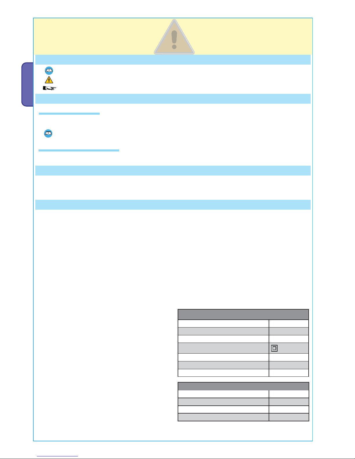
Legend of symbols
This symbol shows parts which must be read with care.
This symbol means the parts which describe safety issues.
This symbol tells you what to tell the end-user.
2 Conditions of use
The ZL170N control panel is engineered to command single 24 V DC powered gearmotors of the FERNI, EMEGA and FROG
series.
Any installation and use other than that specified in this manual is forbidden.
3 Reference standards
"IMPORTANT INSTALLATION SAFETY INSTRUCTIONS"
“WARNING: IMPROPER INSTALL ATION MAY RESULT IN SERIOUS HARM. PLEASE FOLLOW ALL INSTALLATION INSTRUCTIONS”
“THIS MANUAL IS INTENDED ONLY FOR PROFES SIONAL INSTALLERS OR OTHER COMPETENT INDIVIDUALS”
2.2 Application settings
Engineered and built entirely by Came Cancelli Automatici
S.p.A.
The control panel should be powered by 230 V AC, at 50/60
Hz frequency.
The command devices and accessories are powered by 24V.
Warning! The accessories must not exceed 40 W overall.
All connections are protected by quick fuses, see table.
The transformer is fitted with a protection which, in case
overheating, keeps the gate leaf open. Reclosing will happen
only after the temperature has dropped below the overload
limit.
The card provides and controls the following functions:
- automatic closing after an opening command;
- pre-flashing movement indicator;
- obstacle detections when gate is not moving at any point;
- opening recoil:.
The available command modes are:
- opening/closing;
-opening/closing with maintained action;
- open only with radio command;
- total stop.
The photocells, after detecting an obstacle, may trigger:
- the reopening of the closing gate;
- a partial stop if gate is moving;
- a total stop.
The control panel features a safety amperometric sensor (see
p. 12).
Special trimmers regulate:
- the working time for automatic closing;
- adjusting amperometric sensitivity during while gate is
moving: min/max.
- adjusting amperometric sensitivity during deceleration:
min/max
- adjusting the stopping zone final stop (see p. 11)
You can also adjust the gate movement and deceleration
speeds (see p. 12).
You can also connect:
- gate open warning-lamp;
- electro lock.
- Movement flashing light.
- courtesy -lamp lighting the parking area for opening/closing
cycle.
- LB18 board to power gearmotors via batteries in case of
power outages. When power is back on it also recharges
them.
Came Cancelli Automatici employs an ISO 9001:2000 cer tified quality management system and an ISO 14001 environmental
management system. Came entirely engineers and manufactures in Italy.
This product is compliant with: see statement of compliance.
The overall power load of the connected motor must not exceed 180 W.
FUSE TABLE
to protect: fuses for:
Electronic board (line)
3.15 A-F
Command devices (control unit) 630 mA-F
Accessories 3.15 A-F
TECHNICAL DATA
line voltage 230V - 50/60Hz
power draw when idle 120 mA
maximum power for 24 V accessories 40 W
circuit insulation class
container material ABS
container protection rating IP54
working temperature -20 / +55°C
15
32 4 5
6
1
10
14
11
12
7
8
9
13
RA R R C FA F M N
MNR
ADT x ZL170
16
17
P.
3
3 - Manual code
319U34
319U34 ver.
1.0
1.0 09/2011 © CAME cancelli automatici s.p.a. - The data and information in this manual may be changed at any time with no obligation to notify said changes.
ENGLISHENGLISHENGLISH
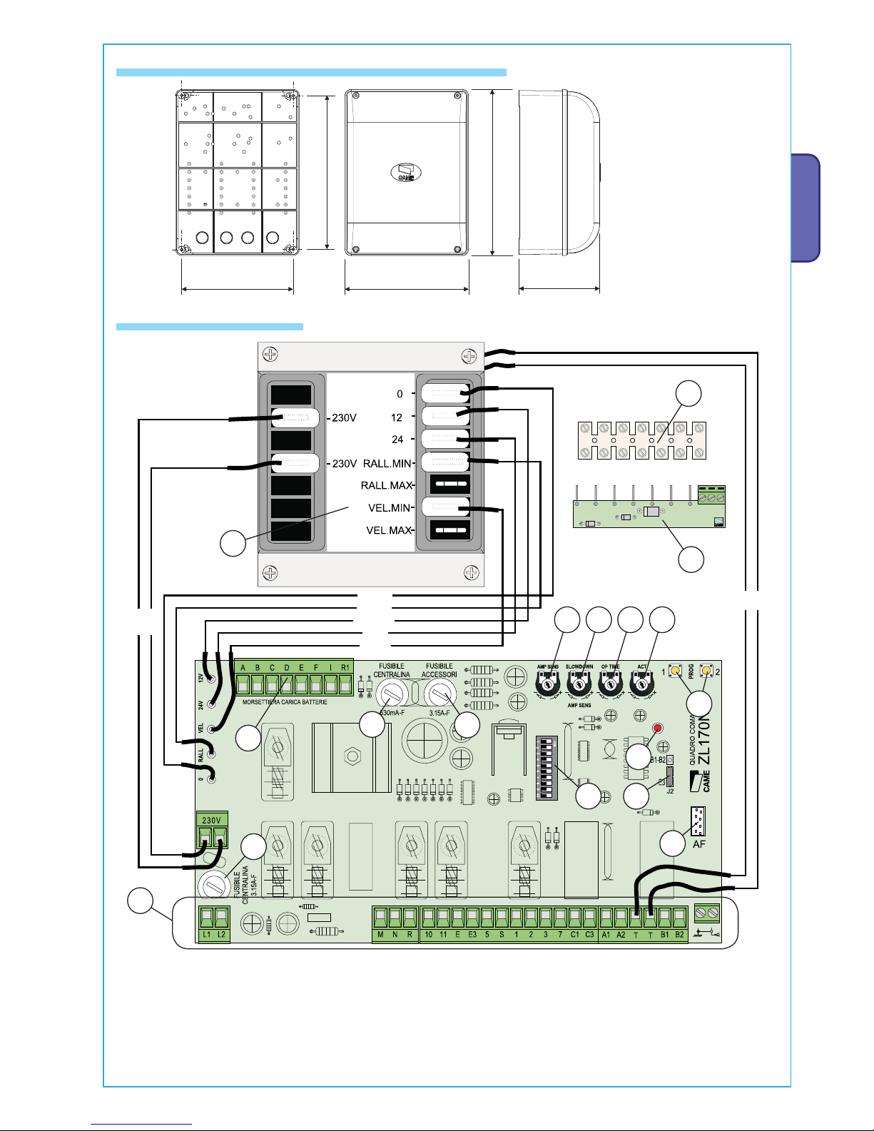
4.1 Dimensions, centre distances and anchoring holes
4.2 Main components
(mm)
1. Transformer
2. Amperometric sensitity during travel
adjustment trimmer
3. Amperometric sensitity during deceleration
adjustment trimmer
4. Opening / closing strike zone adjustment
trimmer
5. Automatic closing adjustement trimmer
6. Code memorising button
7. Terminals for connecting to the
LB18 battery charger (see p. 9)
8. 630mA-F control unit fuse
9. 3.15F accessories fuse
10. Radio code notifi cation LED light
11. Functions selector
12. Output selector jumper B1-B2/cycle lamp
13. 3.15A-F line fuse
14. Radio frequency card socket
15. Connection terminals
16. ADT card for managing
decelerations (see pages 5-6)
17. ADT terminals (use only with Frog
24V, see p. 6)
BLACK
BLUE
BROWN
RED
WHITE
BLUE
PURPLE
P.
4
4 - Manual code
319U34
319U34 ver.
1.0
1.0 09/2011 © CAME cancelli automatici s.p.a. - The data and information in this manual may be changed at any time with no obligation to notify said changes.
ENGLISH
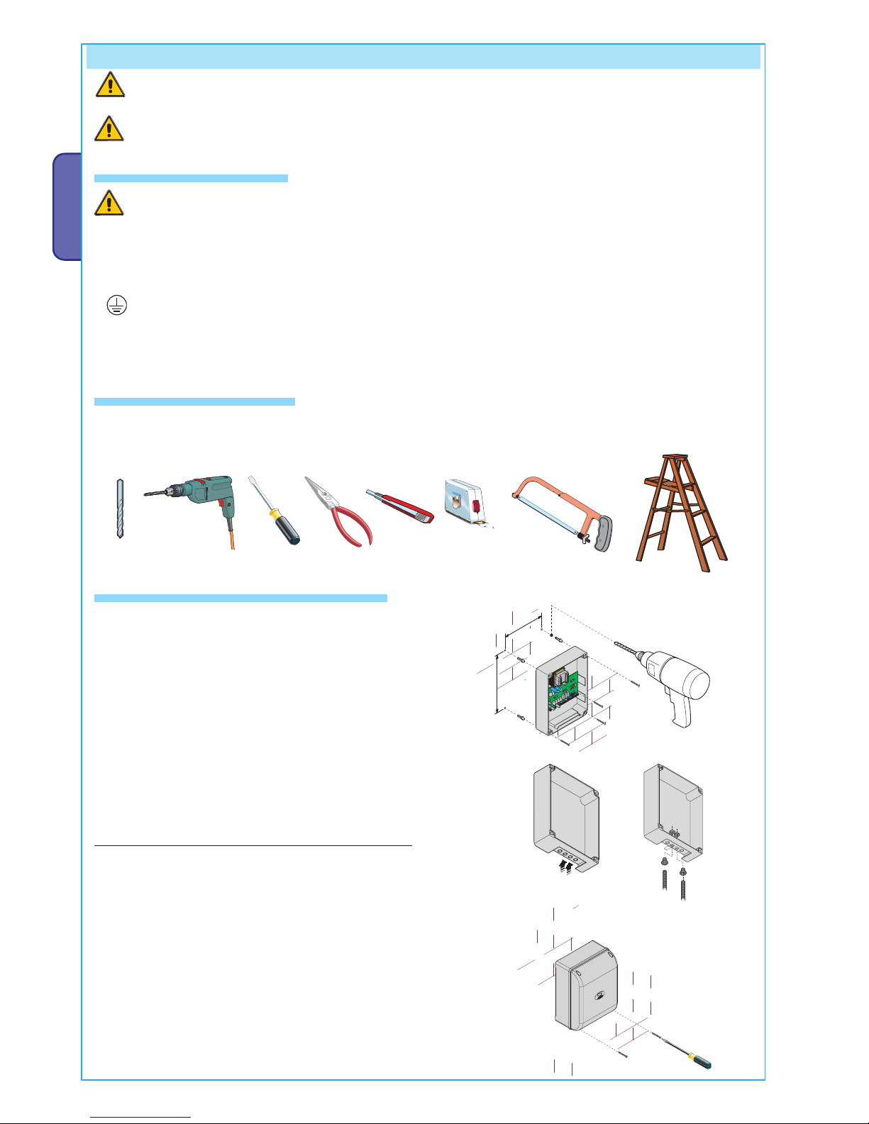
5 Installation
5.1 Preliminary checks
5.2 Tools and equipment
5.3 Anchoring and installing the box
Make sure that the point where the electrical panel is anchored is free from any impacts, and that the surface is solid and that
proper tools and materials are used (i.e. screws, wall plugs, etc.).
Set up a suitable omnipolar cut-off device, with distances greater than 3 mm between contacts, with sectioned power
source
•
Check that any connections inside the container (made for continuity purposes of the protective circuit) are fitted with
extra insulation compared to other internal conductive parts.
• Set up proper conduits and electric cable raceways, making sure these are protected from any mechanical damage.
Make sure you have all the tools and materials needed to carry out the installation in total safety and in accordance with
current regulations. Here are some examples.
Secure the base of the panel in a safe area; we suggest using
bolts with max. diametre of 6 mm Philips rounded heads.
Perforate the marked holes and insert the cable glands with
corrugated tubes for the electrical cables to run through.
N.B.: the pre-perforated holes have different diameters: 23,
29 and 37 mm.
Careful not to damage the electronic board inside the panel!!
After adjusting and setting, secure the cover using the issued
screws.
Before beginning to install, the following is necessary:
Installation must be carried by skilled, qualified technicians in accordance with current regualtions.
Warning! Before acting on the eqipment, cut off the main power supply and disconnect the emergency batteries (if
present).
RA R RC FA F M N
MNR
ADT x ZL170
RA R RC FA F M N
RA R RC FA F M N
MNR
ADT x ZL170
RA R RC FA F M N
FROG
FERNI EMEGA
P.
5
5 - Manual code
319U34
319U34 ver.
1.0
1.0 09/2011 © CAME cancelli automatici s.p.a. - The data and information in this manual may be changed at any time with no obligation to notify said changes.
ENGLISHENGLISHENGLISH
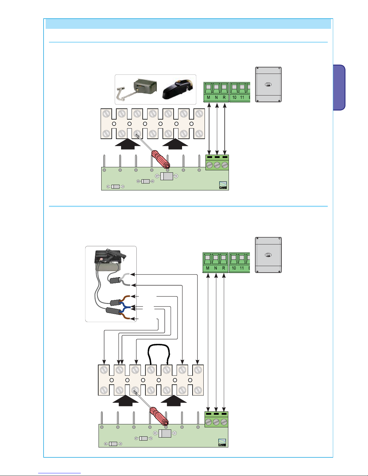
6 Electrical connections
Gearmotor FERNI and EMEGA
The ADT card should be fastened to the gearmotor terminals as shown, and connected to the control panel on terminals M, N
and R (the RA terminal is not active on the FERNI and EMEGA models).
FROG Gearmotor
Whereas with Frog, ADT card and terminals, after connecting to the cables coming out of the gearmotor, they can be left inside the control
panel or in a similar water-tight box.
BROWN
BLUE
BLUE
BROWN
 Loading...