

Page 1
SERIE Z | Z SERIES | SERIE Z
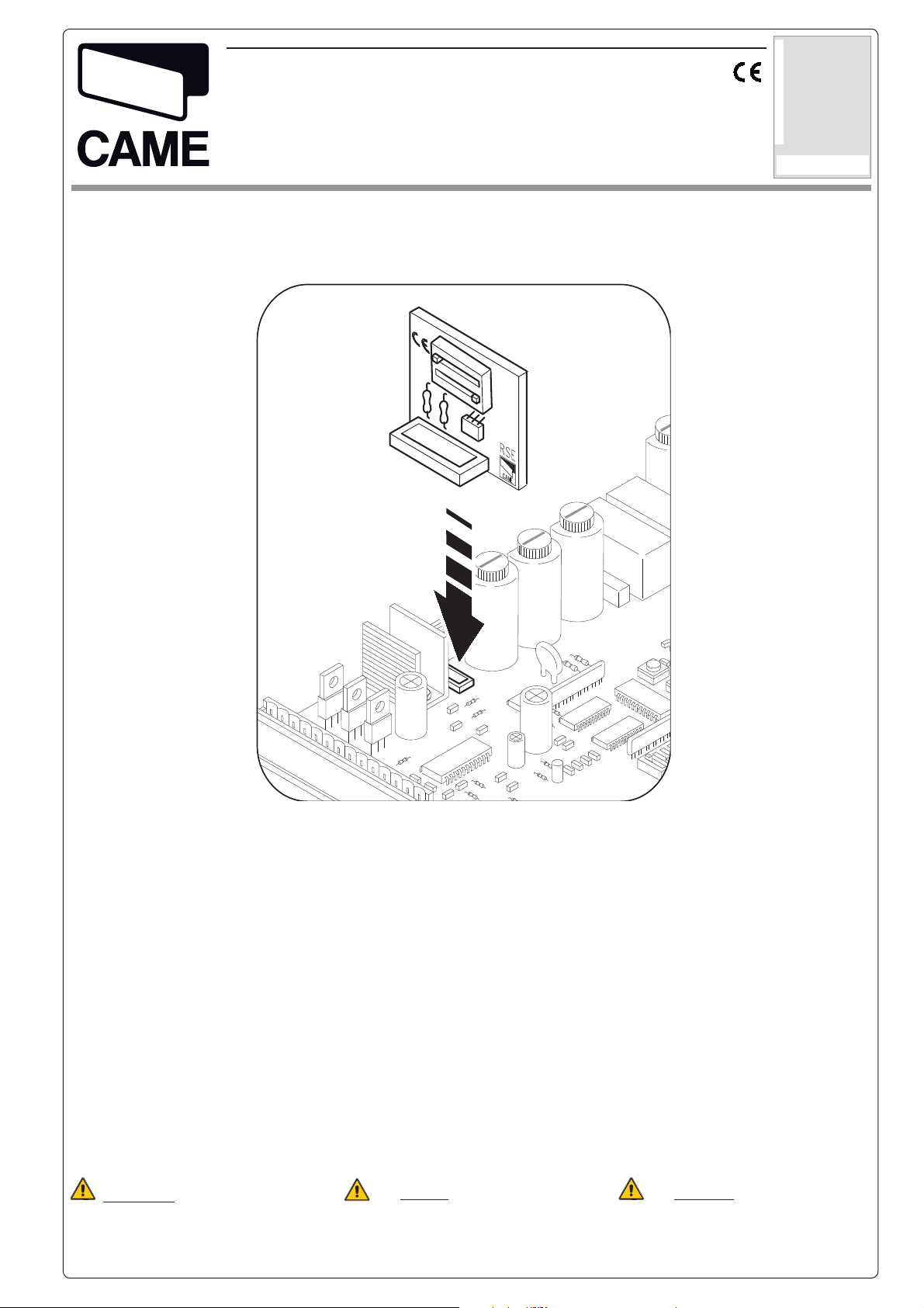
SCHEDA COMANDO RSE
RSE CONTROL BOARD
TARJETA DE MANDO RSE
RSE
SCHEDA GESTIONE FUNZIONE ABBINATA O BUSSOLA PER SCHEDA ZL39 / ZG5
F
UNCTION CONTROL CARD ZL39 / ZG5 CONTROL PANEL
TARJETA GESTIÓN FUNCIÓN COMBINADA O BRÚJULA PARA TARJETA ZL39 / ZG5
Documentazione
Tecnica
T60
rev. 2
05/2013
©
CAME
ITALIANO / ENGLISH / ESPAÑOL
CANCELLI AUTOMATICI
319T60-1
CARATTERISTICHE GENERALI
Prodotto: Progettato e costruito
interamente dalla CAME CANCELLI
AUTOMATICI S.p.a. , rispondente alle
vigenti norme di sicurezza.
Le prestazioni da noi indicate sono
valide solo se il montaggio è stato
eseguito correttamente, secondo le
nostre indicazioni tecniche.
Attenzione: prima di intervenire
all’interno dell’apparecchiatura,
togliere la tensione di linea
GENERAL CHARACTERISTICS
Product: Designed and built entirely by
CAME CANCELLI AUTOMATICI S.p.A.,
in full compliance with current safety
standards.
The declared performances are only
valid if assembly has been performed
according to our technical recommendations.
Caution: before intervening
inside the equipment, ensure the mains
voltage is off.
CARACTERÍSTICAS GENERALES
Producto: Diseñado y fabricado
completamente por CAME CANCELLI
AUTOMATICI S.p.A., responde a las
normas de seguridad vigentes.
Las prestaciones indicadas son
válidas sólo si el montaje ha sido
efectuado correctamente según
nuestras indicaciones técnicas.
Atención: antes de trabajar
en el interior del equipo, corte la
tensión de la línea
Page 2

ITALIANO - ENGLISH - ESPAÑOL
SCHEDA SERIALE RSE / RSE SERIAL BOARD / TARJETA SERIAL RSE
2
1
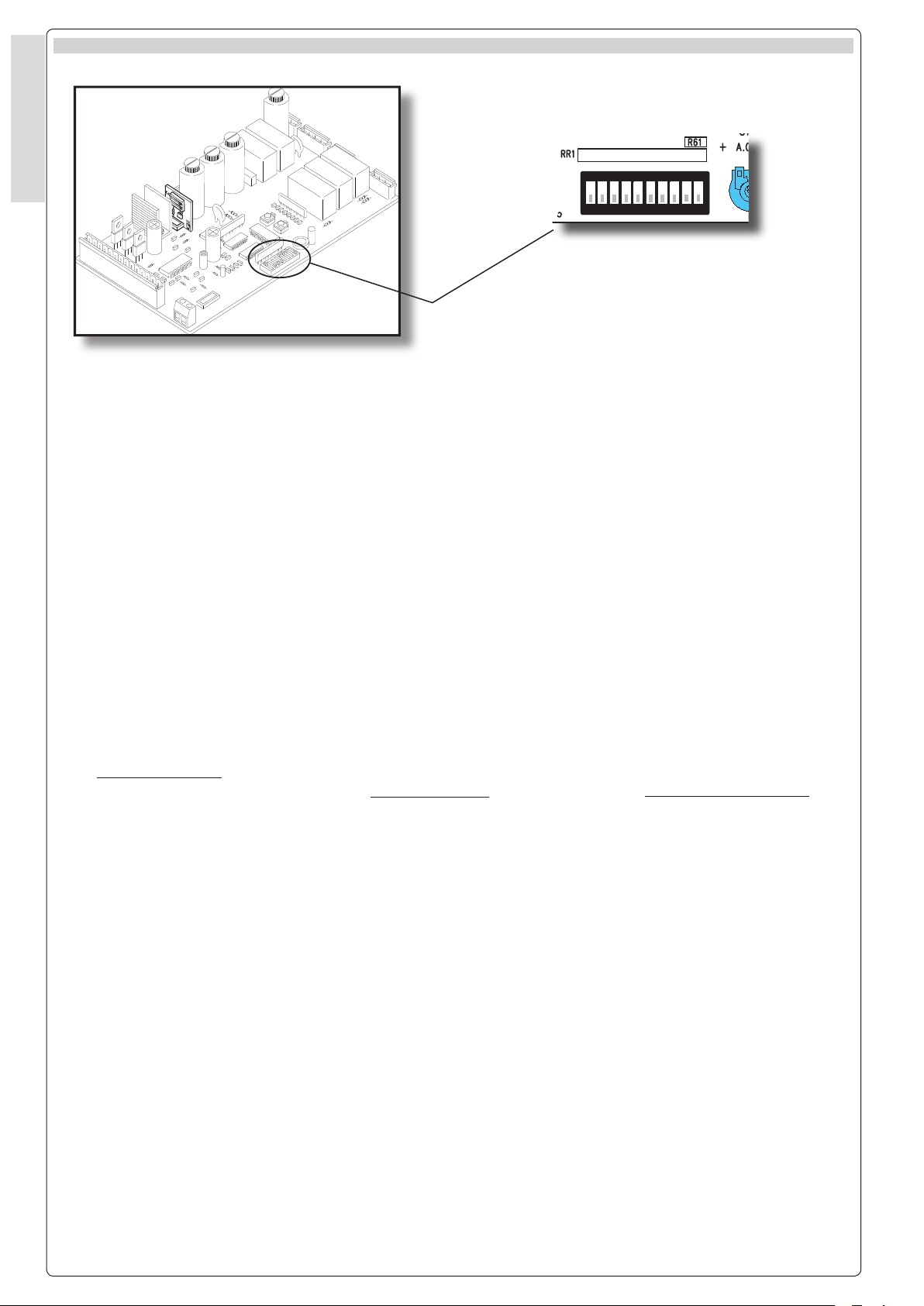
COMPONENTI PRINCIPALI
1-Innesto scheda seriale RSE
(opzionale per collegamento barriere
in abbinato o bussola)
2-Dip-switch funzioni.
SELEZIONI FUNZIONI RSE /
DIP-SWITCH (1-2)
1
ON
OFF
2
INTERLOCK
INTERBLOQUEADAS
ABBINATE
COMBINED
COMBINADAS
BUSSOLA
ON
OFF
MAIN COMPONENTS
1-RSE serial board coupling (optional
for connecting interlock or combined
barriers)
2-Function dip-switches.
COMPONENTES PRINCIPALES
1- Conector tarjeta serial RSE
(opcional para la conexión
de barreras en combinadas o
interbloqueadas)
2-Dip-switches funciones.
RSE FUNCTION SELECTIONS / SELECCIONES DE LAS FUNCIONES RSE
2
1
AF
Dip-Switch RSE:
Inserendo la scheda seriale RSE sulla
scheda ZG5 MASTER si può abilitare
la funzione bussola o abbinato tramite
i dip switch.
ATTENZIONE! Per schede ZL39
consultare la documentazione tecnica
delle barriere della serie GARD4 e
GARD8 con encoder.
2
RSE dip switch:
By inserting the RSE serial board onto
the ZG5 MASTER board, you can use
the dip switches to enable the interlock or
combined functions.
CAUTION! For control board ZL39,
Check the technical documentation of
the Gard4 and Gard8 series barriers w/
encoder.
Dip-Switch RSE:
Conectando la tarjeta serial RSE a
la tarjeta ZG5 MASTER se puede
habilitar, mediante los dip switches, la
función de barrera interbloqueada o
combinada.
¡Precaución! Para tarjeta ZL39
consultar la documentación técnica
sobre barreras de la serie Gard4 y
Gard8 con encoder.
Page 3
3
1)
2)
2 DX
SLAVE
4)
AF
2 SLAVE
2
1
3
4
5
6
7
8 9 10
O
N
DIP- SWITCH
2
1
O
N
DIP- SWITCH
RSE
GND
BA
ABINATO
D
E+
ENCODER
VB 24 12
0
GND
BA
ABINATO
D
E+
ENCODER
VB 24 12
0
1 SX
MASTER
AF
2
1
O
N
DIP- SWITCH
RSE
1 MASTER
3)
ITALIANO - ENGLISH - ESPAÑOL
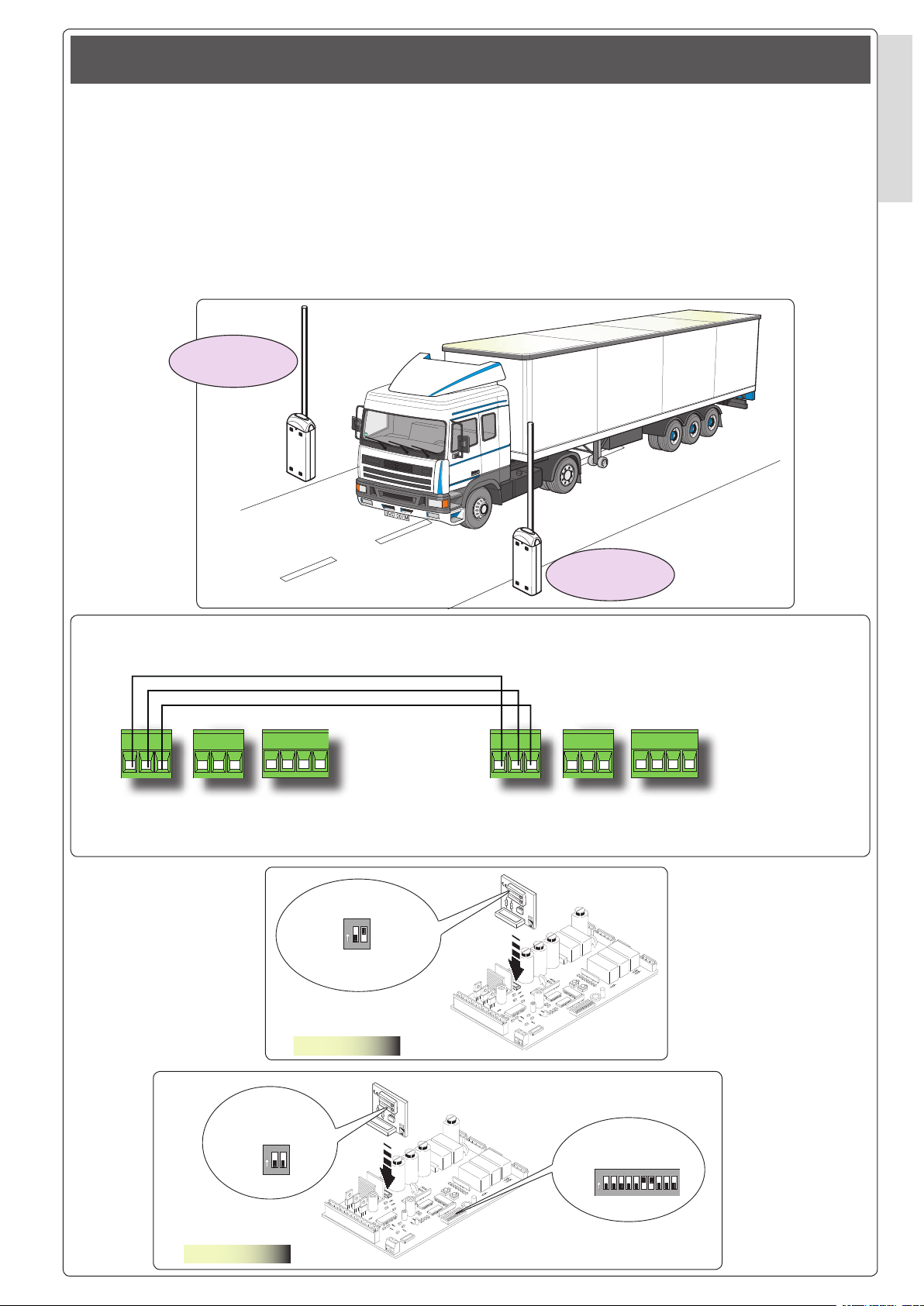
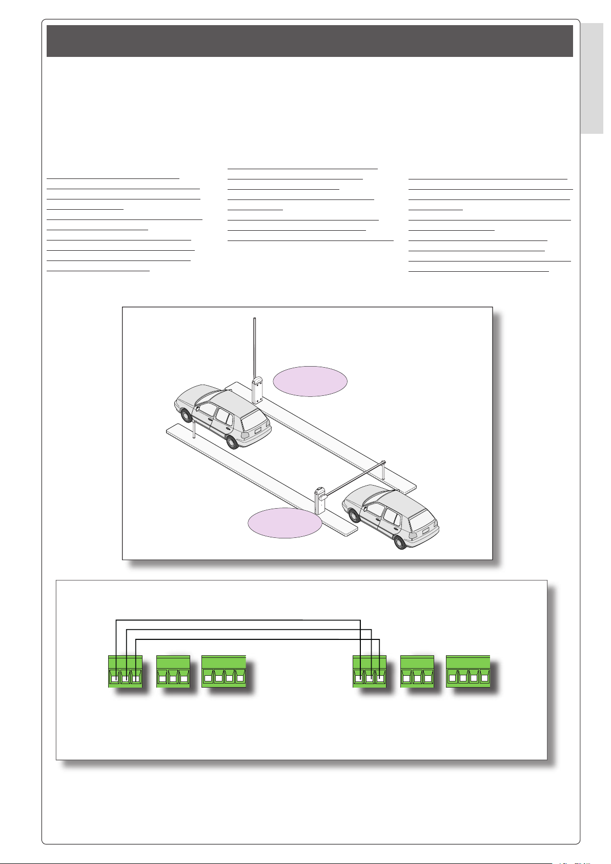
BARRIERE CON FUNZIONE ABBINATO
BARRIERS WITH COMBINED FUNCTION
BARRERAS CON FUNCIÓN COMBINADA
La funzione abbinato permette di
gestire il comando simultaneo di due
barriere.
Inserire su entrambe le barriere la
scheda RSE, collegare le morsettiere
dedicate (ref. 2) per il collegamento
abbinato, posizionare il dip switch
n° 2 in ON della scheda RSE inserita
sulla barriera MASTER e il dip switch
n° 6 e 7 in ON sulla scheda ZG5
barriera SLAVE.
Morsettiera barriera SX MASTER
SX MASTER barrier terminal board
Regleta de conexiones SX MASTER
Morsettiera barriera DX SLAVE
DX SLAVE barrier terminal board
Regleta de conexiones DX SLAVE
NOTA: per la barriera DX vedi collegamento pag. 9-10 della documentazione relativa T41.
NOTE: for the DX barrier, see connection on p. 9-10 of the related documentation T41.
NOTA: para la barrera DX véanse las conexiones de pág. 9-10 de la documentación correspondiente T41.
The combined function allows you to
control two barriers at the same time.
Install the RSE board on both the
barriers, connect the dedicated terminal
boards (ref. 2) for combined connection,
set dip switch no. 2 of the RSE board
installed on the barrier MASTER to ON
and dip switches nos. 6 and 7 to ON on
the SLAVE barrier’s ZG5 board.
La función combinada permite
controlar simultáneamente el
accionamiento de dos barreras.
Conecte en ambas barreras la
tarjeta RSE, conecte las regletas de
conexiones especí cas (ref. 2) para
la conexión combinada, coloque en
ON el dip switch n° 2 de la tarjeta RSE
conectada en la barrera MASTER y
coloque en ON los dip switches n°
6 y 7 en la tarjeta ZG5 en la barrera
SLAVE.
Page 4
4
5
10
11 E6 E7TS1
2
3 4
53P 7C1C5
10
11
E6 E7TS1
2
3 4
53P 7C1C5
MASTER
10-E7
10-E6
SLAVE
10-E6
10-E7
2
3
1
2
2
3P
2
4
2
7
2
C5
ITALIANO - ENGLISH - ESPAÑOL
ITALIANO - ENGLISH - ESPAÑOL
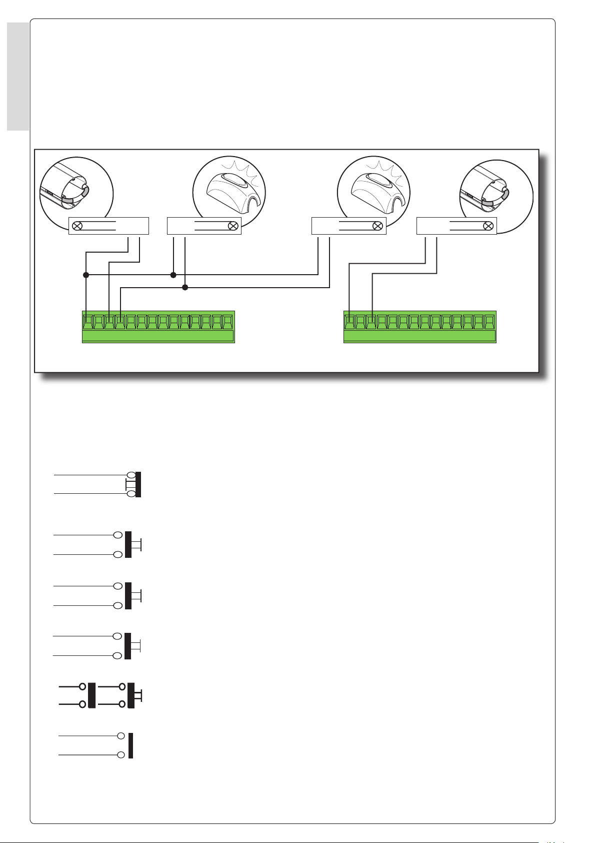
Tutti i dispositivi di comando, di
sicurezza e gli accessori (es. le
cupole lampeggianti delle due
barriere collegate ai morsetti 10-E7)
devono essere collegati alla barriera
MASTER, tranne per il cordone
luminoso collegato sui morsetti 10-E6
di ogni singola barriera.
I dispositivi di comando collegati ai
morsetti della scheda elettronica della
barriera MASTER hanno le seguenti
funzioni:
Pulsante N.C. collegato ai morsetti 1-2 arresta entrambe le barriere (se non utilizzato dip 6 in ON)
Button N.C., connected to terminals 1-2, stops both the barriers (if dip switch 6 is not set to ON)
Botón N.C. conectado a los bornes 1-2 detiene ambas barreras (si no se utiliza el dip 6 se
coloca en ON)
Pulsante N.O. collegato ai morsetti 2-3 apre entrambe le barriere
Button N.O. connected to terminals 2-3 opens both the barriers
Botón N.A. conectado a los bornes 2-3 abre ambas barreras
Pulsante N.O. collegato ai morsetti 2-3P apre la barriera MASTER
Button N.O. connected to terminals 2-3P opens the MASTER barrier
Botón N.A. conectado a los bornes 2-3P abre la barrera MASTER
Pulsante N.O. collegato ai morsetti 2-4 chiude entrambe le barriere
Button N.O. connected to terminals 2-4 closes both the barriers
Botón N.A. conectado a los bornes 2-4 cierra ambas barreras
Pulsante N.O. collegato ai morsetti 2-7 apre-chiude-inverte entrambe le barriere
Button N.O. connected to terminals 2-7 opens-closes-reverses both barriers
Botón N.A. conectado a los bornes 2-7 abre - cierra ambas barreras
Contatto N.O. collegato ai morsetti 2-C5 per chiusura immediata delle barriere.
N.O. contact connected to terminals 2-C5, for immediate barrier closure.
Contacto N.A. conectado a los bornes 2-C5 para cierre inmediato de las barreras.
All the command, safety and accessory
devices (e.g. the ashing domes of the
two barriers connected to terminals 10E7) must be connected to the MASTER
barrier except for the ourescent tube
connected on terminals 10-E6 of each
barrier.
The command devices connected to
terminals of the MASTER barrier’s
electronic board have the following
functions:
Todos los dispositivos de mandos,
de seguridad y los accesorios (ej.:
las luces intermitentes tipo cúpula
de la dos barreras conectadas
a los bornes 10-E7) deben estar
conectados a la barrera MASTER,
salvo por el cordón luminoso
conectado en los bornes 10-E6 de
cada barrera.
Los dispositivos de mando
conectados a los bornes de la tarjeta
electrónica de la barrera MASTER
tienen las siguientes funciones:
Page 5
5
U
VW
FC
FA
F
ON
2
1 3 4 5 6 7 8 9
10
EB
EB
VS CT L2T
L1T
INTERBLOCCO
N
L
GND
BA
ABINATO
D
E+
ENCODER
VB 24 12
0
10
11
E6
E7
TS
1
2
3
3P
4
5
7
C1
C5
U
VW
FC
FA
F
ON
2
1 3 4 5 6 7 8 9
10
EB
EB
VS CT L2T
L1T
INTERBLOCCO
N
L
GND
BA
ABINATO
D
E+
ENCODER
VB 24 12
0
10
11
E6
E7
TS
1
2
3
3P
4
5
7
C1
C5
MASTER
RSE
MASTER
ITALIANO - ENGLISH - ESPAÑOL
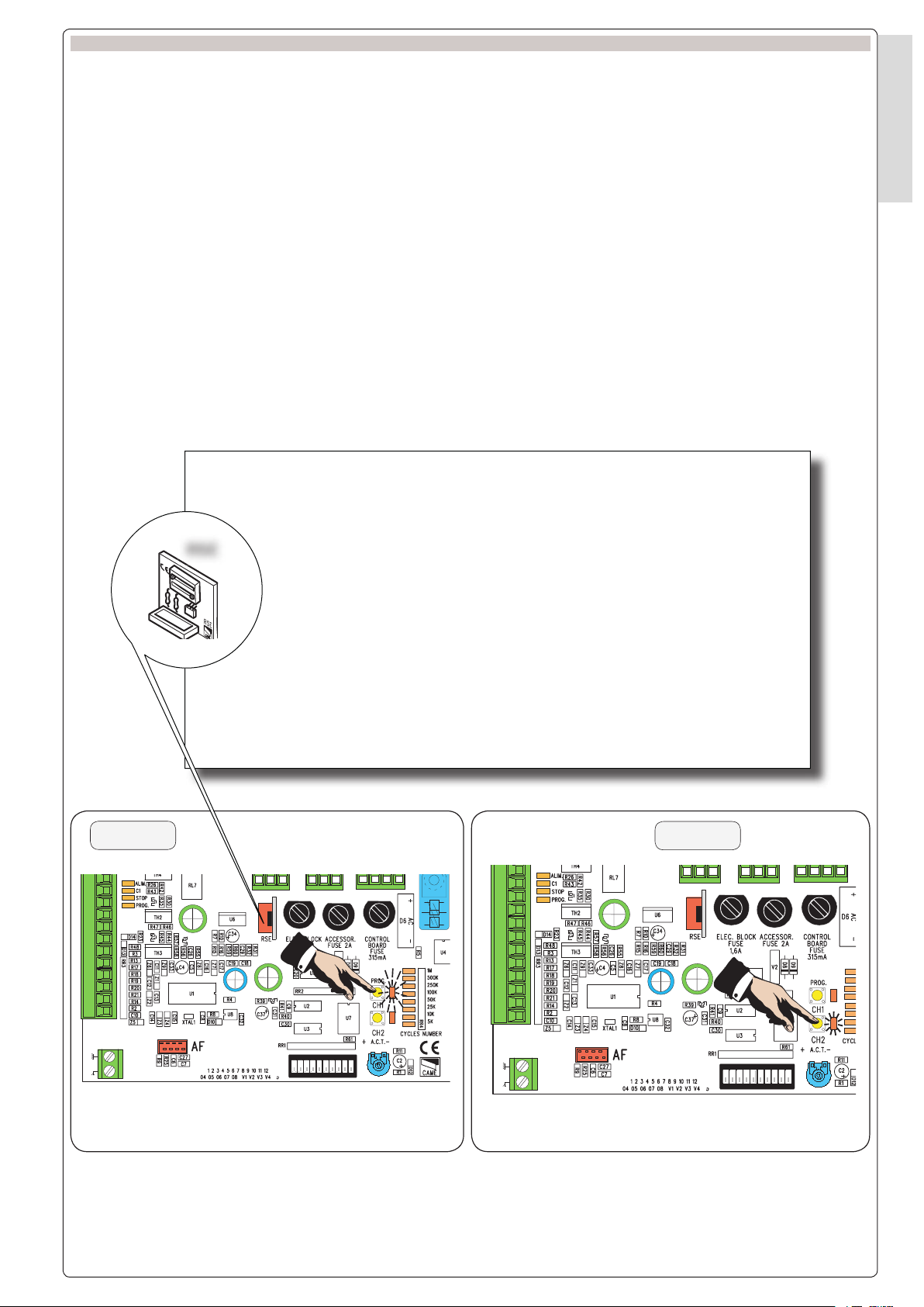
INSTALLAZIONE DEL RADIOCOMANDO - INSTALLING THE RADIO-CONTROL - INSTALACIÓN DEL RADIOMANDO
PROCEDURA
A - Inserire la scheda AF solo sulla
barriera MASTER.
B - Memorizzare la codi ca del
trasmettitore radio sulla scheda
base.
1)Il canale radio CH1 gestisce il
comando delle barriere MASTER e
SLAVE e il trasmettitore esegue la
seguente funzione:
Dip n° 2 OFF- Comando “apre-chiudeinversione”
Dip n° 2 ON- Comando “apertura”
2)Il canale radio CH2 gestisce il
comando della barriera MASTER e
il radiocomando esegue la funzione
“apre-chiude-inversione”
Il canale radio CH1:
dip n°2 = OFF esegue l’inversione della barriera.
dip n°2 = ON esegue il comando di sola apertura.
N.B. L’impulso del canale radio CH2 non viene gestito se in presenza di una
sola barriera.
The CH1 radio channel:
dip switch no. 2 = OFF reverses the barrier’s direction of movement.
dip switch no. 2 = ON performs the open command only.
N.B. The impulse of the CH2 radio channel is not managed if there is only one
barrier.
El canal radio CH1:
dip n°2 = OFF ejecuta la inversión de la barrera.
dip n°2 = ON ejecuta el mando de sólo apertura.
N.B: El impulso del canal radio CH2 no es controlado si hay montada una
barrera sola.
PROCEDURE
A - Install the AF board only on the MA-
STER barrier.
B - Save the code of the radio transmit-
ter on the motherboard.
1)The CH1 radio channel commands
the MASTER and SLAVE barriers and
the transmitter performs the following
function:
Dip switch no. 2 OFF- “Open-closereverse” command
Dip switch no. 2 ON - “Opening”
command
2)The CH2 radio channel commands the
MASTER barrier and the radio-control
performs the “open-close-reverse”
function
PROCEDIMIENTO
A - Conecte la tarjeta AF sólo en la
barrera MASTER.
B - Memorice la codi cación del
transmisor radio en la placa base.
1)El canal radio CH1 controla el accionamiento de las barreras MASTER
y SLAVE y el transmisor efectúa la
siguiente función:
Dip n° 2 OFF- Mando “abrir-cerrar-inversión”
Dip n° 2 ON- Mando “abrir”
2)El canal radio CH2 controla el accionamiento de la barrera MASTER
y el radiomando efectúa la función
“abrir-cerrar-inversión”
Page 6
6
7
AF
ON
2
1 3 4 5 6 7 8 9
10
DIP SWITCH (1-10)
ITALIANO - ENGLISH - ESPAÑOL
ITALIANO - ENGLISH - ESPAÑOL
SELEZIONI FUNZIONI /
FUNCTION SELECTIONS
/
SELECCIONES DE LAS FUNCIONES.
1 ON Funzione chiusura automatica
attivata; (1 OFF-disattivata)(da
abilitare solo sulla barriera
MASTER);
2 ON Funzione "apre" con trasmettitore
radio (scheda AF inserita)
attivato(da abilitare solo sulla
barriera MASTER);
2 OFF Funzione "apre-chiude-inversione"
con pulsante (2-7) e trasmettitore
radio (scheda AF inserita)
attivato(da abilitare solo sulla
barriera MASTER);
3 ON Funzione ad "azione mantenuta"
(esclude la funzione del
trasmettitore radio) attivato; (3
OFF disattivato)(da abilitare solo
sulla barriera MASTER);
4 ON Prelampeggio in apertura e in
chiusura attivato, con dispositivo
collegato sui morsetti 10- E7 (4
OFF disattivato)(da abilitare solo
sulla barriera MASTER);
5 ON Rilevazione ostacolo. A motore
fermo (barriera chiusa, aperta o
dopo un comando di stop totale),
impedisce qualsiasi movimento
se i dispositivi di sicurezza (es.
fotocellule) rilevano un ostacolo
(5 OFF disabilitato)(da abilitare
solo sulla barriera MASTER);
6 OFF Funzione di stop totale (collegare
pulsante su 1-2) attivato;(se non
utilizzato posizionare il dip in ON);
7 OFF Funzione di riapertura in fase di
chiusura (collegare i dispositivi
di sicurezza sui morsetti 2C1) attivata; (se non utilizzato
posizionare il dip in ON);
8 ON Funzione del test di sicurezza
per la veri ca dell’ef cienza delle
fotocellule (pag. 6) attivato; (8 OFF
disattivata).
9 OFF Encoder attivato per la gestione
dei rallentamenti in apertura e
chiusura degli ostacoli (9 ON
disattivato);
10 Non utilizzato
1 ON Automatic closing function
enabled; (1 OFF-disabled)(to be
enabled only on the MASTER
barrier);
2 ON “Open” function with radio
transmitter (AF board inserted)
enabled(to be enabled only on
the MASTER barrier);
2 OFF Function “open-close-reverse”
with pushbutton (2-7) and radio
transmitter (AF board inserted)
enabled(to be enabled only on
the MASTER barrier);
3 ON “Maintained action” function
(excludes the radio transmitter)
enabled; (3 OFF disabled)(to be
enabled only on the MASTER
barrier);
4 ON Pre- ashing while opening and
closing enabled, with device
connected to terminals 10-E7 (4
OFF disabled)(to be enabled only
on the MASTER barrier);
5 ON Obstacle detection. With motor
not running (barrier closed, open
or after a total-stop command),
all movement is prevented if the
safety devices (e.g. photoelectric
cells) detect an obstacle (5 OFF
disabled)(to be enabled only on
the MASTER barrier);
6 OFF Total-stop function (connect
pushbutton to 1-2) enabled; (if not
used, set dip-switch to ON);
7 OFF Re-opening during closure func-
tion (connect the safety devices
to terminals 2-C1) enabled; (if not
used, set dip-switch to ON);
8 ON Safety test function to check
photoelectric cell ef ciency (page
6) enabled; (8 OFF disabled).
9 OFF Encoder enabled for managing
obstacle slow-downs during opening and closing (9 ON disabled);
10 Not used
1 ON Función cierre automático
activa; (1 OFF-desactivada)(se
habilita sólo en la barrera
MASTER);
2 ON Función “abrir” con transmisor
radio (tarjeta AF conectada)
activa (se habilita sólo en la
barrera MASTER);
2 ON Función “abrir- cerrar- inver-
sión” con botón (2-7) y transmisor radio (tarjeta AF conectada) activa (se habilita sólo en
la barrera MASTER);
3 ON Función “accionamiento con-
tinuo” (excluye la función del
transmisor radio) activa (3 OFF
desactivada) (habilitar sólo en
la barrera MASTER);
4 ON Predestello en apertura y en
cierre activo , con dispositivo
conectado en los bornes10- E7
(4 OFF desactivada) (se habilita sólo en la barrera MASTER);
5 ON- Detección de obstáculos. Con
el motor detenido (barrera
cerrada, abierta o después de
un mando de parada total), impide cualquier movimiento si
los dispositivos de seguridad
(por. ej. fotocélulas) detectan
un obstáculo (5 OFF deshabilitada) (se habilita sólo en la
barrera MASTER);
6 OFF Función de parada total (co-
necte el botón en 1-2) activa;
(si no se utiliza, coloque el dip
en ON);
7 OFF Función de apertura durante
el cierre (conecte los dispositivos de seguridad a los bornes
2-C1) activa; (si no se utiliza,
coloque el dip en ON);
8 ON Función del test de seguridad
para el control del funcionamiento de las fotocélulas (pág.
6) activa; (8 OFF desactivada).
9 OFF Encoder activo para la ges-
tión de las desaceleraciones
durante la apertura y el cierre
en el caso de detección de
obstáculos (9 ON desactivada);
10 No utilizado
Page 7
7
2)
GND
BA
ABINATO
D
E+
ENCODER
VB 24 12
0
GND
BA
ABINATO
D
E+
ENCODER
VB 24 12
0
1)
1
MASTER
2
SLAVE
ITALIANO - ENGLISH - ESPAÑOL
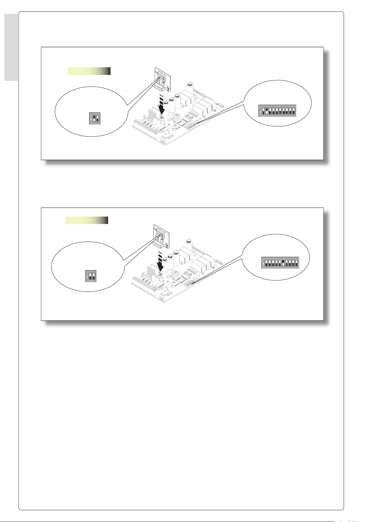
BARRIERE CON FUNZIONE BUSSOLA
BARRIERS WITH INTERLOCK FUNCTION
BARRERAS CON FUNCIÓN INTERBLOQUEADA
Inserire su entrambe le barriere la
scheda RSE, collegare le morsettiere
dedicate per il collegamento
abbinato, posizionare il dip switch
n° 1 in ON della scheda RSE inserita
sulla barriera MASTER e il dip switch
n° 6 in ON sulla scheda ZG5 barriera
SLAVE.
N.B. Per ottenere dopo il ciclo
completo di apertura e chiusura di
una barriera, l’apertura automatica
dell’altra barriera.
Posizionare il dip switch n° 2 in ON
della barriera MASTER.
La funzione BUSSOLA mantiene
bloccata la barriera MASTER no
a quando la barriera SLAVE è in
movimento e viceversa.
Install the RSE board on both the
barriers, connect the dedicated terminal
boards for the combined connection,
set dip switch no. 1 on the RSE board
installed on the MASTER barrier to ON,
and set dip switch no. 6 on the SLAVE
barrier’s ZG5 board to ON.
N.B. To automatically open the other
barrier after the complete barrier
opening and closure cycle,
set dip switch no. 2 of the MASTER
barrier to ON.
The INTERLOCK function keeps the
MASTER barrier locked while the
SLAVE barrier is moving and vice versa.
Conecte en ambas barreras la
tarjeta RSE, conecte las regletas de
conexiones especí cas (ref. 2) para
la conexión combinada, coloque en
ON el dip switch n° 1 de la tarjeta RSE
conectada en la barrera MASTER, y
coloque en ON el dip switch n° 6 en
la tarjeta ZG5 de la barrera SLAVE.
N.B. Para obtener después del ciclo
completo de apertura y cierre de una
barrera, la apertura automática de la
otra barrera.
Coloque en ON el dip switch n° 2 de
la barrera MASTER.
La función INTERBLOQUEADA
mantiene bloqueada la barrera
MASTER mientras la barrera SLAVE
esté en movimiento y viceversa.
Morsettiera barriera SX MASTER
SX MASTER barrier terminal board
Regleta de conexiones SX MASTER
Morsettiera barriera DX SLAVE
DX SLAVE barrier terminal board
Regleta de conexiones DX SLAVE
NOTA: per la barriera DX vedi collegamento pag. 9-10 della documentazione relativa T41.
NOTE: for the DX barrier, see connection on p. 9-10 of the related documentation T41.
NOTA: para la barrera DX véanse las conexiones de pág. 9-10 de la documentación correspondiente T41.
Page 8
8
9
3)
AF
2
1
3
4
5
6
7
8 9 10
O
N
DIP- SWITCH
2
1
O
N
DIP- SWITCH
RSE
1 MASTER
4)
AF
2 SLAVE
2
1
3
4
5
6
7
8 9 10
O
N
DIP- SWITCH
2
1
O
N
DIP- SWITCH
RSE
ITALIANO - ENGLISH - ESPAÑOL
ITALIANO - ENGLISH - ESPAÑOL
Page 9

9
10
11 E6 E7TS1
2
3 4
53P 7C1C5
10
11
E6 E7TS1
2
3 4
53P 7C1C5
MASTER
10-E7
10-E6
10-E7
10-E6
SLAVE
2-C1
2-C5
2-C1
2-C5
Esempio :
ITALIANO - ENGLISH - ESPAÑOL
Tutti i dispositivi di comando
devono essere collegati alla
barriera MASTER, mentre per ogni
barriera effettuare i collegamenti del
dispositivo di sicurezza collegato
ai morsetti 2-C1 (es. fotocellula con
funzione di riapertura), del dispositivo
(es. spira magnetica) collegato ai
morsetti 2-C5 (chiusura immediata) e
degli accessori di segnalazione (es.
lampeggiatore a cupola e cordone
luminoso).
Per aprire entrambe le barriere,
azionare il dispositivo di comando
collegato ai morsetti 2-3, a barriera
aperta azionare il dispositivo
di sicurezza (pulsante di stop
obbligatotio) collegato ai morsetti 1-2
e azionare il dispositivo di comando
collegato ai morsetti 2-3P per aprire
la seconda barriera.
In caso di emergenza se si
aziona manualmente lo sblocco
del motoriduttore con chiave e si
posiziona in apertura una barriera
l’altra viene disinibita.
All the command devices must be
connected to the MASTER barrier, while
for all barriers perform the connections
of the safety device connected to
terminals 2-C1 (e.g. photoelectric cell
with re-opening function), the device
(e.g. magnetic coil) connected to
terminals 2-C5 (immediate closure)
and of the signalling accessories (e.g.
ashing dome lamp and ourescent
tube).
To open both the barriers, activate the
command device connected to terminals
2-3, with the barrier open, activate the
safety device (compulsory stop button)
connected to terminals 1-2 and run the
command device connected to terminals
2-3P to open the second barrier.
In the event of an emergency if you
manually release the gearmotor using
a key and move a barrier to its open
position, the other one is released.
Todos los dispositivos de mando
deben conectarse a la barrera
MASTER, mientras que para
cada barrera hay que conectar el
dispositivo de seguridad conectado
a los bornes 2-C1 (ej.: fotocélula con
función de apertura), del dispositivo
(por ej. lazo magnético) conectado a
los bornes 2-C5 (cierre inmediato) y
de los accesorios de señalización (ej.
luz intermitente tipo cúpula y cordón
luminoso).
Para abrir ambas barreras, accione
el dispositivo de mando conectado a
los bornes 2-3, con la barrera abierta
accione el dispositivo de seguridad
(botón de parada obligatoria)
conectado a los bornes 1-2 y accione
el dispositivo de mando conectado a
los bornes 2-3P para abrir la segunda
barrera.
En caso de emergencia si se acciona
manualmente el desbloqueo del
motorreductor con llave y se abre
una barrera, la otra se dishinibe.
Page 10

11
ITALIANO - ENGLISH - ESPAÑOL
COLLEGAMENTI ELETTRICI
/
ELECTRICAL CONNECTIONS
/
CONEXIONES ELÊCTRICAS
I dispositivi di comando collegati ai
morsetti della scheda elettronica della
barriera MASTER hanno le seguenti
funzioni:
ITALIANO - ENGLISH - ESPAÑOL
1
2
2
3
2
3P
2
4
Pulsante (N.C.) arresta entrambe le barriere
Pushbutton (N.C.) stops both the barriers
Botón (N.C. ) detiene ambas barreras
Pulsante (N.O.) apre solo la barriera MASTER
Pushbutton (N.O.) opens the MASTER barrier only
Botón (N.A. ) abre sólo la barrera MASTER.
Pulsante (N.O.) apre solo la barriera SLAVE
Pushbutton (N.O.) opens the SLAVE barrier only
Botón (N.A. ) abre sólo la barrera MASTER.
Pulsante (N.O.) chiude solo la barriera MASTER
Pushbutton (N.O.) closes the MASTER barrier only
Botón (N.A. ) cierra sólo la barrera MASTER.
The command devices connected to
terminals of the MASTER barrier’s
electronic board have the following
functions:
Los dispositivos de mando
conectados a los bornes de la tarjeta
electrónica de la barrera MASTER
tienen las siguientes funciones:
2
7
N.B. Per la funzione di chiusura
automatica attivare dip swicth 1 ON
su entrambe le barriere.
Pulsante (N.O.) chiude solo la barriera SLAVE
Pushbutton (N.O.) closes the SLAVE barrier only
Botón (N.A. ) cierra sólo la barrera SLAVE.
N.B. To activate the automatic-closing
function, set dip switch 1 to ON for both
the barriers.
N.B. Para la función de cierre
automático active el dip swicth 1 ON
en ambas barreras.
10
Page 11

11
U
VW
FC
FA
F
ON
2
1 3 4 5 6 7 8 9
10
EB
EB
VS CT L2T
L1T
INTERBLOCCO
N
L
GND
BA
ABINATO
D
E+
ENCODER
VB 24 12
0
U
VW
FC
FA
F
ON
2
1 3 4 5 6 7 8 9
10
EB
EB
VS CT L2T
L1T
INTERBLOCCO
N
L
GND
BA
ABINATO
D
E+
ENCODER
VB 24 12
0
MASTER
RSE
SLAVE
ITALIANO - ENGLISH - ESPAÑOL
INSTALLAZIONE DEL RADIOCOMANDO - RADIO CONTROL INSTALLATION - INSTALACIÓN DEL RADIOMANDO
PROCEDURA
A - Inserire la scheda AF solo sulla
barriera MASTER.
B - Memorizzare la codi ca sulla
scheda.
1)Il canale radio CH1 comanda la
barriera MASTER e il trasmettitore
esegue la seguente funzione:
Dip n° 2 OFF- Comando “apre-chiudeinversione”
Dip n° 2 ON- Comando “apertura”
2)Il canale radio CH2 comanda la
barriera SLAVE e il trasmettitore
esegue la seguente funzione:
Dip n° 2 in OFF- Comando “aprechiude-inversione”
Dip n° 2 in ON- Comando “apertura”
N.B. L’impulso del canale radio CH2
non viene gestito se in presenza di
una sola barriera.
1)The CH1 radio channel commands
the MASTER barrier and the transmitter
performs the following function:
Dip switch no. 2 OFF- “Open-close-reverse” command
Dip switch no. 2 ON - “Opening” command
2)The CH2 radio channel commands the
SLAVE barrier and the transmitter performs the following function:
Dip switch no. 2 OFF- “Open-close-reverse” command
Dip switch no. 2 ON- “Opening” command
N.B. The impulse of the CH2 radio
channel is not managed if there is only
one barrier.
1)El canal radio CH1 acciona la
barrera MASTER y el transmisor
efectúa la siguiente función:
Dip n° 2 OFF- Mando “abrir-cerrarinversión”
Dip n° 2 ON- Mando “abrir”
2)El canal radio CH2 acciona la
barrera SLAVE y el transmisor
efectúa la siguiente función:
Dip n° 2 OFF- Mando “abrir-cerrarinversión”
Dip n° 2 ON- Mando “abrir”
N.B: El impulso del canal radio CH2
no es controlado si hay montada una
barrera sola.
PROCEDURE
A - Install the AF board only on the MA-
STER barrier.
B - Save the code of the radio transmit-
ter on the motherboard.
PROCEDIMIENTO
A - Conecte la tarjeta AF sólo en la
barrera MASTER.
B - Memorice la codi cación del
transmisor radio en la placa base.
Page 12

CAME CANCELLI AUTOMATICI S.P.A.
D
OSSON DI CASIER (TREVISO)
(+39) 0422 4940 (+39) 0422 4941
SISTEMA QUALITÅ
CERTIFICATO
ASSISTENZA TECNICA
NUMERO VERDE
800 295830
W
EB
www.came.it
E-MAIL
info@came.it
Documentazione
Tecnica
T60
rev. 0.1
07/2004
©
CAME
CANCELLI AUTOMATICI
RSE
AF
ON
2
1
3 4 5 6 7 8 9 10
DIP SWITCH (1-10)
Tut ti i dati sono sta ti con trol la ti con la mas si ma cura. Non ci
as su mia mo co mun que al cu na re spon sa bi li tà per even tua li errori
od omissioni.
All data checked with the maximum care. However, no liability is accepted
for any error or omission.
Todos los datos se han controlado con la máxima atención.
No obstante no nos responsabilizamos de los posibles errores
u omisiones.
319T60-1
SERIE Z | Z SERIES | SERIE Z
ITALIANO / ENGLISH / ESPAÑOL
SCHEDA COMANDO RSE
RSE CONTROL BOARD
TARJETA DE MANDO RSE
SELEZIONI FUNZIONI / FUNCTION SELECTIONS / SELECCIONES DE LAS FUNCIONES
1 ON “Automatic closing” function
enabled; (1 OFF-disabled) (to be
enabled on both barriers);
2 OFF “Open-close-reverse” function
with pushbutton (2-7) and radio
transmitter activated (to be enabled only on MASTER barrier);
3 ON “Maintained action” function ena-
bled (excludes the radio transmitter function); (3 OFF disabled)(to
be enabled only on MASTER
barrier);
4 ON Pre- ashing while opening and
closing enabled, with device
connected on terminals 10- E7 (4
OFF disabled)
5 ON Obstacle detection. With motor
not running (barrier closed, open
or after a total stop command),
any movement is prevented if the
safety devices (e.g. photoelectric
cells) detect an obstacle (5 OFF
disabled)(to be enabled only on
MASTER barrier);
6 OFF Total-stop function (connect
pushbutton to 1-2) enabled; (if not
used, set dip-switch to ON);
7 OFF Re-opening function during clo-
sure (connect the safety devices
on terminals
2-C1) enabled; (if not used, set
dip-switch to ON);
8 ON Safety test function to check
photoelectric cell ef ciency (p. 6)
enabled; (8 OFF disabled).
9 OFF Encoder enabled for managing
obstacle slow-downs during opening and closing (9 ON disabled);
10 Not used
1 ON Función”cerrar automático”
activa; (1 OFF-desactivada) (se
habilita en ambas barreras);
2 OFF Función “abrir- cerrar- inver-
sión” con botón (2-7) y transmisor radio activa (se habilita
sólo en la barrera MASTER);
3 ON Función “accionamiento con-
tinuo” (excluye la función del
transmisor radio) activa (3 OFF
desactivada) (se habilita sólo
en la barrera MASTER);
4 ON Predestello durante la aper-
tura y cierre activa, con dispositivo conectado a los bornes
10- E7 (4 OFF desactivada);
5 ON- Detección de obstáculos. Con
el motor detenido (barrera
cerrada, abierta o después de
un mando de parada total), impide cualquier movimiento si
los dispositivos de seguridad
(por. ej. fotocélulas) detectan
un obstáculo (5 OFF deshabilitada) (se habilita sólo en la
barrera MASTER);
6 OFF Función de parada total (co-
necte el botón en 1-2) activa;
(si no se utiliza, coloque el dip
en ON);
7 OFF Función de apertura durante
el cierre (conecte los dispositivos de seguridad a los bornes
2-C1) activa; (si no se utiliza,
coloque el dip en ON);
8 ON Función del test de seguridad
para el control del funcionamiento de las fotocélulas (pág.
6) activa; (8 OFF desactivada).
9 OFF Encoder activo para la ges-
tión de las desaceleraciones
durante la apertura y cierre en
el caso de detección de obstáculos (9 ON desactivada);
10 No utilizado
1 ON Funzione “chiusura automati-
ca” attivata; (1 OFF-disattivata)
(da abilitare su entrambe le
barriere);
2 OFF Funzione “apre-chiude-inver-
sione” con pulsante (2-7) e
trasmettitore radio attivato(da
abilitare solo sulla barriera
MASTER);
3 ON Funzione ad “azione mante-
nuta” (esclude la funzione del
trasmettitore radio) attivato;
(3 OFF disattivato)(da abilitare
solo sulla barriera MASTER);
4 ON Prelampeggio in apertura e in
chiusura attivato, con dispositivo collegato sui morsetti 10- E7
(4 OFF disattivato)
5 ON Rilevazione ostacolo. A motore
fermo (barriera chiusa, aperta
o dopo un comando di stop
totale), impedisce qualsiasi
movimento se i dispositivi
di sicurezza (es. fotocellule)
rilevano un ostacolo (5 OFF
disabilitato)(da abilitare solo
sulla barriera MASTER);
6 OFF Funzione di stop totale
(collegare pulsante su 1-2)
attivato;(se non utilizzato posizionare il dip in ON);
7 OFF Funzione di riapertura in fase di
chiusura (collegare i dispositivi
di sicurezza sui morsetti
2-C1) attivata; (se non utilizzato
posizionare il dip in ON);
8 ON Funzione del test di sicurezza
per la veri ca dell’ef cienza
delle fotocellule (pag. 6) attivato; (8 OFF disattivata).
9 OFF Encoder attivato per la gestio-
ne dei rallentamenti in apertura
e chiusura degli ostacoli (9 ON
disattivato);
10 Non utilizzato
Page 13

SERIE Z | Z SERIES | SERIE Z
CARTE DE COMMANDE RSE
COMMANDOSCHEMA RSE
STEUERKARTEN RSE
RSE
Documentazione
Tecnica
T60
rev. 2
05/2013
FRANCESE/NEDERLAND/DEUTSCHALND
©
CAME
CANCELLI AUTOMATICI
319T60-2
CARTE GESTION FONCTION COMBINÉE OU OUVERTURE PAR PIVOTEMENT POUR CARTE ZL39 / ZG5
BEHEERPRINTPLAAT VOOR FUNCTIE SAMENWERKING OF SLUISWERKING VOOR KAART ZL39 / ZG5
STEUERPLATINE FÜR PARALLEL- BZW. SCHLEUSENFUNKTION FÜR STEUERUNG ZL39 / ZG5
CARACTÉRISTIQUES GÉNÉRALES
Produit : Conçu et fabriqué
entièrement par CAME CANCELLI
AUTOMATICI S.p.a., il satisfait aux
normes en vigueur en matière de
sécurité.
Les performances indiquées ne
sont valables que si le montage a
été effectué correctement, comme
d’après les indications techniques
fournies.
Attention : couper le courant
avant d’intervenir à l’intérieur de
l’appareil
ALGEMENE KENMERKEN
Product: Volledig ontworpen en gebouwd
door CAME CANCELLI AUTOMATICI
S.p.a. , volgens de geldende
veiligheidsnormen.
De door ons aangeduide prestaties zijn
enkel geldig indien de montage correct
werd uitgevoerd volgens de door ons
geleverde technische instructies.
Opgelet: alvorens handelingen
uit te voeren op de apparatuur moet
elektrische voeding losgekoppeld worden
de
ALLGEMEINE EIGENSCHAFTEN
Produkt: unter Beachtung der
geltenden Sicherheitsvorschriften
vollständig von der CAME CANCELLI
AUTOMATICI S.p.a. geplant und
gebaut.
Die von uns angegebenen Leistungen
gelten nur bei korrekt durchgeführter
Montage laut unseren technischen
Anweisungen.
Achtung: vor Eingriffen
im Inneren des Geräts ist die
Leitungsspannung zu unterbrechen.
Page 14

FRANÇAIS - NEDERLANDS - DEUSCH
CARTE SÉQUENTIELLE RSE / SERIËLE RSE KAART / RSE-SERIENKARTE
2
1
PRINCIPAUX COMPOSANTS
1-raccord carte séquentielle RSE
(en option pour branchement des
barrières accouplées ou douille)
2-Microcontacts fonctions.
SÉLECTION DES FONCTIONS RSE
DIP-SWITCH (1-2)
KOKER
KOMBIFUNKTIONEN
ACCOUPLÉES
GEKOPPELDE
SCHRANKEN
DOUILLE
SLAGBOMEN
KOMPASS
ENEN
ON
OFF
ON
OFF
1
BELANGRIJKSTE ONDERDELEN
1-Aansluiting seriële RSE kaart (optie
voor aansluiting van gekoppelde of koker
slagbomen)
2-Dip-switch functies.
/
SELECTIES VAN DE RSE FUNCTIES / WAHL DER RSE-FUNKTIONEN
2
1
WESENTLICHE BAUTEILE
1-Steckanschluss der RSE-
Serienkarte (optional zum Anschluss
von Schranken mit Kompass- oder
Kombifunktion.)
2-Dip-switch Funktionen.
AF
2
Microcontact RSE :
La fonction douille ou accouplées peut
être activée à l’aide des microcontacts
en mettant la carte séquentielle RSE
sur la carte ZG5 MASTER.
ATTENTION! Pour carte ZL39,
consulter la documentation technique
des barrières de la série Gard4 et
Gard8 avec encodeur.
2
Dip-Switch RSE:
Door de seriële RSE kaart op de ZG5
MASTER kaart in te steken kan de
functie koker of gekoppeld geactiveerd
worden via de dip switches.
Opgelet! Printplaat ZL39,
raadpleeg de technische documentatie
van de slagbomen van de serie Gard4
en Gard8 met encoder.
RSE-Dip-Switch:
Bei Einfügen der RSW-Serienkarte auf
der ZG5-MASTER-Karte kann mit Hilfe
der Dip-switch die Kompass- oder
Kombifunktion aktiviert werden.
ACHTUNG! Steuerung ZL39,
Siehe technische Anleitungen der
Schrankensysteme Serien Gard4 und
Gard8 mit Encoder.
Page 15

3
1)
2)
2 DX
SLAVE
4)
AF
2 SLAVE
2
1
3
4
5
6
7
8 9 10
O
N
DIP- SWITCH
2
1
O
N
DIP- SWITCH
RSE
GND
BA
ABINATO
D
E+
ENCODER
VB 24 12
0
GND
BA
ABINATO
D
E+
ENCODER
VB 24 12
0
1 SX
MASTER
AF
2
1
O
N
DIP- SWITCH
RSE
1 MASTER
3)
FRANÇAIS - NEDERLANDS - DEUSCH
REMARQUE: pour la barrière DROITE, voir branchement pages 9-10 de la documentation T41 correspondante.
OPM.: voor de rechter slagboom: aansluiting pag. 9-10 op de bijbehorende documentatie T41.
ANMERKUNG: für die rechte Schranke siehe Anschluss Seite 9-10 der entsprechenden Dokumentation T41.
BARRIÈRES AVEC FONCTION ACCOUPLÉES
SLAGBOMEN MET FUNCTIE GEKOPPELD
SCHRANKEN MIT KOMBI-FUNKKTION
La fonction accouplées permet de
gérer la commande simultanée de
deux barrières.
Placer la carte RSE sur les deux
barrières, raccorder les borniers
spéci ques (réf. 2) pour le
branchement accouplées, mettre le
microcontact n° 2 de la carte RSE
qui se trouve sur la barrière MASTER
et les microcontacts n° 6 et 7 de la
carte ZG5 qui se trouve sur la barrière
SLAVE sur ON.
Bornier barrière GAUCHE MASTER SX
Klemmenbord linker MASTER slagboom
Klemmenbrett HAUPT-Schranke SX
Met de functie gekoppeld kan men
gelijktijdig twee slagbomen besturen.
Steek in beide slagbomen de RSE kaart,
sluit de betreffende klemmenborden aan
(ref. 2) voor de gekoppelde aansluiting,
plaats de dip switch n° 2 op ON gelegen
op de RSE kaart ingestoken van de
MASTER slagboom en de dip switch n°
6 en 7 op ON gelegen op de ZG5 kaart
van de SLAVE slagboom.
Mit der Kombi-Funktion können
gleichzeitig zwei Schranken gesteuert
werden.
Auf beiden Schranken die RSE-Karte
einfügen, für den Anschluss der
Kombi-Funktion die entsprechenden
Klemmenbretter (Bez. 2) anschließen,
den Dip-switsch N° 2 der RSE-Karte
auf der HAUPT-Schranke auf ON und
die Dip-switch N° 6 und 7 auf der
ZG5-Karte der NEBEN-Schranke auf
ON positionieren.
Bornier barrière SLAVE DX
Klemmenbord linker SLAVE slagboom
Klemmenbrett NEBEN DX
Page 16

4
5
10
11 E6 E7TS1
2
3 4
53P 7C1C5
10
11
E6 E7TS1
2
3 4
53P 7C1C5
MASTER
10-E7
10-E6
SLAVE
10-E6
10-E7
2
3
1
2
2
3P
2
4
2
7
2
C5
FRANÇAIS - NEDERLANDS - DEUSCH
FRANÇAIS - NEDERLANDS - DEUSCH
Tous les dispositifs de commande,
de sécurité et les accessoires (ex.
les coupoles clignotantes des deux
barrières branchées aux bornes
10-E7) doivent être branchés à la
barrière MASTER, sauf le cordon
lumineux branché aux bornes 10-E6
de chaque barrière.
Les dispositifs de commande
branchés aux bornes de la carte
électronique de la barrière MASTER
ont les fonctions suivantes :
Le bouton N.F. branché aux bornes 1-2 arrête les deux barrières (s’il n’est pas utilisé, le
microcontact 6 doit être sur ON)
Knop N.C. aangesloten op de klemmen 1-2 stopt beide slagbomen (indien niet gebruikt: dip 6 in ON)
Die an den Klemmen 1-2 angeschlossene Drucktaste N.C. hält beide Schranken an (wenn
nicht Dip 6 auf ON benutzt wird).
Le bouton N.O. branché aux bornes 2-3 ouvre les deux barrières
Knop N.O. aangesloten op de klemmen 2-3 opent beide slagbomen
Die an den Klemmen 2-3 angeschlossene Drucktaste N.O. öffnet beide Schranken.
Le bouton N.O. branché aux bornes 2-3P ouvre la barrière MASTER
Knop N.O. aangesloten op de klemmen 2-3P opent de MASTER slagboom
Die an den Klemmen 2-3P angeschlossene Drucktaste N.O. öffnet die HAUPT-Schranke.
Le bouton N.O. branché aux bornes 2-4 ferme les deux barrières
Knop N.O. aangesloten op de klemmen 2-4 sluit beide slagbomen
Die an den Klemmen 2-4 angeschlossene Drucktaste N.O. schließt beide Schranken.
Le bouton N.O. branché aux bornes 2-7 ouvre-ferme-inverse les deux barrières
Knop N.O. aangesloten op de klemmen 2-7 open-sluit-ommekeer beide slagbomen
Die an den Klemmen 2-7 angeschlossene Drucktaste öffnet - schließt beide Schranken und
steuert sie um.
Contact N.O. branché aux bornes 2-C5 pour la fermeture immédiate des barrières.
Contact N.O. aangesloten op de klemmen 2-C5 voor onmiddellijke sluiting van de slagbomen.
Der an den Klemmen 2-C5 angeschlossene Kontakt N.O. dient zur sofortigen Schließung der
Schranke .
Alle stuur- en veiligheidsinrichtingen en
de accessoires (bv. de maanvormige
knipperlichten van de twee slagbomen
aangesloten op de klemmen 10-E7)
moeten aangesloten zijn op de MASTER
slagboom, behalve de lichtgevende buis,
aangesloten op de klemmen 10-E6 van
elke slagboom.
De stuurinrichtingen aangesloten op
de klemmen van de elektronische kaart
van de MASTER slagboom hebben de
volgende functies:
Alle Steuer- und Sicherhei
tsvorrichtungen, sowie die
Zubehörteile (z.B. Blinkkuppeln
der beiden am Klemmenbrett 10E7 angeschlossenen Schranken)
müssen an der HAUPT-Schranke,
außer der an den Klemmen 10E6 jeder einzelnen Schranke
angeschlossenen Leuchtschnur,
angeschlossen sein.
Die an den Klemmen der
Elektronikkarte der HAUPTSchranke angeschlossenen
Steuervorrichtungen haben folgende
Funktionen:
Page 17

5
U
VW
FC
FA
F
ON
2
1 3 4 5 6 7 8 9
10
EB
EB
VS CT L2T
L1T
INTERBLOCCO
N
L
GND
BA
ABINATO
D
E+
ENCODER
VB 24 12
0
10
11
E6
E7
TS
1
2
3
3P
4
5
7
C1
C5
U
VW
FC
FA
F
ON
2
1 3 4 5 6 7 8 9
10
EB
EB
VS CT L2T
L1T
INTERBLOCCO
N
L
GND
BA
ABINATO
D
E+
ENCODER
VB 24 12
0
10
11
E6
E7
TS
1
2
3
3P
4
5
7
C1
C5
MASTER
RSE
MASTER
FRANÇAIS - NEDERLANDS - DEUSCH
INSTALLATION DE LA RADIOCOMMANDE - INSTALLATIE VAN DE AFSTANDSBEDIENING - INSTALLATION DER FUNKTSTEUERUNG
Le canal radio CH1 :
microcontact n° 2 = OFF procède à l’inversion de la barrière.
microcontact n° 2 = ON ne commande que l’ouverture.
N.B. L’impulsion du canal radio CH2 n’est pas gérée s’il n’y a qu’une seule barrière.
Het radiokanaal CH1:
dip n°2 = OFF zorgt voor de ommekeer van de slagboom.
dip n°2 = ON zorgt enkel voor de opening.
N.B. De impuls van het radiokanaal CH2 wordt niet bestuurd indien er slechts één slagboom
aanwezig is.
Der Funkkanal CH1 :
dip n°2 = OFF nimmt die Umsteuerung der Schranke vor.
dip n°2 = ON nimmt nur die Öffnungssteuerung vor.
N.B. Bei nur einer Schranke wird der Impuls des Funkkanals CH2 nicht verwaltet.
PROCÉDURE
A – Ne placer la carte AF que sur la
barrière MASTER.
B - Mémoriser le code de l’émetteur
radio sur la carte de base.
1) Le canal radio CH1 gère la
commande des barrières MASTER
et SLAVE et l’émetteur a la fonction
suivante :
Microcontact n° 2 sur OFF –
Commande “ouvre-ferme-inversion”
Microcontact n° 2 sur ON- Commande
“ouverture”
2) Le canal radio CH2 gère la
commande de la barrière MASTER
et la radiocommande a la fonction
*ouvre-ferme-inversion”
WERKWIJZE
A – Steek de AF kaart enkel in de
MASTER slagboom.
B – Sla de code van de radiotransmitter
op de basiskaart op.
1)Het radiokanaal CH1 bestuurt de
MASTER en SLAVE slagbomen en de
transmitter heeft de volgende functie:
Dip n° 2 OFF- Commando “open-sluitommekeer”
Dip n° 2 ON- Commando “openen”
2)Het radiokanaal CH2 bestuurt
de MASTER slagboom en de
afstandsbediening heeft de volgende
functie open-sluit-ommekeer”
PROZEDUR
A – Die Karte AF ausschließlich auf
der HAUPT-Schranke einfügen.
B – Den Code des Senders auf der
Grundkarte speichern.
1) Der Funkkanal CH1 verwaltet die
Steuerung der HAUPT- und NEBEN
-Schranken und die Funksteuerung
führt die folgende Funktion aus:
Dip n° 2 OFF- Steuerung “öffnenschließen.-umsteuern “
Dip n° 2 ON- Steuerung „öffnen”
2) Der Funkkanal CH2 verwaltet
die Steuerung der HAUPT Schranke und die Funksteuerung
nimmt die „Öffnung- Schließung
– Umsteuerung” aus.
Page 18

6
7
AF
ON
2
1 3 4 5 6 7 8 9
10
DIP SWITCH (1-10)
FRANÇAIS - NEDERLANDS - DEUSCH
FRANÇAIS - NEDERLANDS - DEUSCH
SÉLECTION DES FONCTIONS
/
SELECTIES VAN DE FUNCTIES
/
WAHL DER FUNKTIONEN
1 ON Fonction fermeture auto-
matique activée ; (1 OFFdésactivée)(à n’activer que sur
la barrière MASTER) ;
2 ON Fonction «ouvre» avec émet-
teur radio (carte AF insérée)
activé (à n’activer que sur la
barrière MASTER) ;
2 OFF Fonction «ouvre-ferme-in-
version» avec bouton (2-7)
et émetteur radio (carte AF
insérée) activé (à n’activer que
sur la barrière MASTER) ;
3 ON Fonction dont «l’action reste
maintenue» (exclut la fonction
de l’émetteur radio) activée ;
(3 OFF désactivée)(à n’activer
que sur la barrière MASTER) ;
4 ON Pré-clignotement en ouverture
et en fermeture activé, avec
dispositif branché aux bornes
10- E7 (4 OFF désactivé)(à
n’activer que sur la barrière
MASTER) ;
5 ON Détection d’obstacle. Lorsque
le moteur est arrêté (barrière
fermée, ouverte ou après une
commande d’arrêt total), elle
empêche tout mouvement si
les dispositifs de sécurité (ex.
photocellules) détectent un
obstacle (5 OFF désactivée)(à
n’activer que sur la barrière
MASTER) ;
6 OFF Fonction d’arrêt total (brancher
le bouton sur 1-2) activée ; (si
elle n’est pas utilisée, mettre le
microcontact sur ON) ;
7 OFF Fonction de réouverture durant
la phase de fermeture (brancher les dispositifs de sécurité
aux bornes 2-C1) activée ; (si
elle n’est pas utilisée, mettre le
microcontact sur ON) ;
8 ON Fonction du test de sécurité
pour le contrôle de l’ef cacité
des photocellules (page 6)
activée ; (8 OFF désactivée) ;
9 OFF Encodeur activé pour la ges-
tion des ralentissements en
ouverture et en fermeture des
obstacles (9 ON désactivé) ;
10 Pas utilisé
1 ON Functie automatische sluiting ac-
tief; (1 OFF-uitgeschakeld)(enkel
te activeren op de MASTER
slagboom);
2 ON Functie “open” met radiotrans-
mitter (AF kaart ingestoken)
actief(enkel te activeren op de
MASTER slagboom);
2 OFF Functie “open-sluit-ommekeer”
met knop (2-7) en radiotransmitter (AF kaart ingestoken)
actief(enkel te activeren op de
MASTER slagboom);
3 ON Werking met ingedrukte knop
(sluit de functie van de radiotransmitter uit) actief; (3 OFF
uitgeschakeld)(enkel te activeren
op de MASTER slagboom);
4 ON Vooraf knipperen tijdens openen
en sluiten actief, met inrichting
aangesloten met de klemmen 10E7 (4 OFF uitgeschakeld)(enkel
te activeren op de MASTER
slagboom);
5 ON Detectie van obstakel. Met stil-
staande motor (slagboom gesloten, open of na een commando
voor totale stop), verhindert elk
soort beweging indien de veiligheidsinrichtingen (bv. fotocellen)
een obstakel detecteren (5 OFF
uitgeschakeld)(enkel te activeren
op de MASTER slagboom);
6 OFF Functie totale stop (knop aan-
sluiten op 1-2) actief; (indien niet
gebruikt: dip op ON plaatsen);
7 OFF Functie heropening tijdens
sluitingsfase actief (sluit de
veiligheidsinrichtingen aan op
de klemmen 2-C1); (indien niet
gebruikt: dip op ON plaatsen);
8 ON Functie veiligheidstest voor de
controle van de ef ciëntie van de
fotocellen (pag. 6) actief; (8 OFF
uitgeschakeld).
9 OFF Encoder actief voor het beheer
van de vertragingen tijdens opening en sluiting bij obstakels (9
ON uitgeschakeld);
10 Niet gebruikt
1 ON Automatik-Schließung akti-
viert; (1 OFF-deaktiviert)(nur
auf der HAUPT-Schranke zu
aktivieren);
2 ON Funktion “öffnen” mit Funk-
sender (Karte AF eingefügt)
aktiviert (nur auf der HAUPTSchranke zu aktivieren);
2 OFF Funktion “öffnen-schließen-
umsteuern” mit Drucktaste
(2-7) und Funksender (Karte
AF eingefügt) aktiviert (nur
auf der HAUPT-Schranke zu
aktivieren);
3 ON Funktion “andauernde Betä-
tigung “ (schließt die Funktion
des Funksenders aus) aktiviert; (3 OFF deaktiviert) (nur
auf der HAUPT-Schranke zu
aktivieren);
4 ON Vorheriges Blinken beim
Öffnen und Schließen mit der
Vorrichtung auf den Klemmen
10- E7 aktiviert (4 OFF deaktiviert) (nur auf der HAUPTSchranke zu aktivieren;
5 ON Hindernisfeststellung. Bei
nicht laufendem Motor
(Schranke geschlossen, offen
oder nach einem Gesamtstopp), wird jede beliebige Bewegung verhindert, wenn die
Sicherheitsvorrichtungen ein
Hindernis feststellen (5 OFF
deaktiviert)(nur auf der HAUPTSchranke zu aktivieren);
6 OFF Gesamtstopp (Drucktaste auf
1-2 anschließen) aktiviert;
(falls nicht benutzt, den Dip auf
ON stellen);
7 OFF Erneute Öffnung während
der Schließung (die Sicherheitsvorrichtungen auf den
Klemmen 2-C1 anschließen)
aktiviertM; (falls nicht benutzt,
den Dip auf ON stellen);
8 ON Sicherheitstest zur Überprü-
fung der Photozellenfunktionsfähigkeit (Seite 6) aktiviert; (8
OFF deaktiviert).
9 OFF Encoder zur Verwaltung der
Verlangsamungen beim Öffnen
und Schließen im Fall von
Hindernissen aktiviert (9 ON
deaktiviert);
10 Nicht benutzt
Page 19

7
2)
GND
BA
ABINATO
D
E+
ENCODER
VB 24 12
0
GND
BA
ABINATO
D
E+
ENCODER
VB 24 12
0
1)
1
MASTER
2
SLAVE
FRANÇAIS - NEDERLANDS - DEUSCH
BARRIÈRES AVEC FONCTION DOUILLE
SLAGBOMEN MET FUNCTIE KOKER
SCHRANKE MIT KOMPASS-FUNKTION
Placer la carte RSE sur les deux
barrières, brancher les borniers
spéci ques pour le branchement
accouplées, mettre le microcontact
n° 1 de la carte RSE placée sur la
barrière MASTER et le microcontact
n° 6 de la carte ZG5 sur la barrière
SLAVE sur ON.
N.B. Pour obtenir l’ouverture
automatique de l’autre barrière après
le cycle complet d’ouverture et de
fermeture d’une barrière.
Mettre le microcontact n° 2 de la
barrière MASTER sur ON.
La fonction DOUILLE maintient la
barrière MASTER bloquée tant que la
barrière SLAVE est en mouvement et
inversement.
Steek op de beide slagbomen de
RSE kaart in, sluit de betreffende
klemmenborden aan voor de aansluiting
“gekoppeld”, plaats de dip switch n° 1 op
ON gelegen op de RSE kaart ingestoken
op de MASTER slagboom en de dip
switch n° 6 in ON gelegen op de ZG5
kaart van de SLAVE slagboom.
N.B. Voor de automatische opening van
de andere slagboom na de volledige
openings- en sluitcyclus van een
slagboom:
Plaats de dip switch n° 2 op ON van de
MASTER slagboom.
De functie koker houdt de MASTER
slagboom geblokkeerd zolang de SLAVE
slagboom in beweging is en omgekeerd.
Auf beiden Schranken die RSE-Karte
anbringen, die entsprechenden
Klemmenbretter für den kombinierten
Anschluss anbringen, den „dip
switsch” N° 1 der RSE-Karte der
MASTER-Schranke auf ON und den
„dip switsch” N° 6 auf der ZG5 Karte
der NEBEN-Schranke auf ON stellen.
N.B. Um nach einem vollständigen
Öffnungs- und Schließungszyklus
einer Schranke die andere Schranke
automatisch öffnen zu können, ist wie
folgt vorzugehen:
Den „dip switch” N° 2 der HAUPTSchranke auf ON stellen.
REMARQUE: pour la barrière DROITE, voir branchement pages 9-10 de la documentation T41 correspondante.
OPM.: voor de rechter slagboom: aansluiting pag. 9-10 op de bijbehorende documentatie T41.
ANMERKUNG: für die rechte Schranke siehe Anschluss Seite 9-10 der entsprechenden Dokumentation T41.
Bornier barrière GAUCHE MASTER SX
Klemmenbord linker MASTER slagboom
Klemmenbrett HAUPT-Schranke SX
Bornier barrière SLAVE DX
Klemmenbord linker SLAVE slagboom
Klemmenbrett NEBEN DX
Page 20

8
9
3)
AF
2
1
3
4
5
6
7
8 9 10
O
N
DIP- SWITCH
2
1
O
N
DIP- SWITCH
RSE
1 MASTER
4)
AF
2 SLAVE
2
1
3
4
5
6
7
8 9 10
O
N
DIP- SWITCH
2
1
O
N
DIP- SWITCH
RSE
FRANÇAIS - NEDERLANDS - DEUSCH
FRANÇAIS - NEDERLANDS - DEUSCH
Page 21

9
10
11 E6 E7TS1
2
3 4
53P 7C1C5
10
11
E6 E7TS1
2
3 4
53P 7C1C5
MASTER
10-E7
10-E6
10-E7
10-E6
SLAVE
2-C1
2-C5
2-C1
2-C5
Esempio :
FRANÇAIS - NEDERLANDS - DEUSCH
) Tous les dispositifs de commande
doivent être reliés à la barrière
MASTER, tandis qu’il faut brancher
le dispositif de sécurité relié aux
bornes 2-C1 (ex. photocellule avec
fonction de réouverture), le dispositif
(ex. spire magnétique) relié aux
bornes 2-C5 (fermeture immédiate)
et les accessoires de signalisation
(ex. lampe clignotante à coupole
et cordon lumineux) pour chaque
barrière.
Pour ouvrir les deux barrières,
actionner le dispositif de commande
relié aux bornes 2-3. Quand la
barrière est ouverte, actionner le
dispositif de sécurité (bouton d’arrêt
obligatoire) relié aux bornes 1-2 et
actionner le dispositif de commande
relié aux bornes 2-3P pour ouvrir la
seconde barrière.
En cas d’urgence, une des
deux barrières est désactivée
en actionnant manuellement le
déblocage du motoréducteur avec la
clé et en positionnant l’autre barrière
en ouverture.
Alle stuurinrichtingen moeten op de
MASTER slagboom aangesloten zijn,
terwijl u voor elke slagboom moet
zorgen voor de aansluitingen van
de veiligheidsinrichting aangesloten
op de klemmen 2-C1 (bv. fotocel
met heropeningsfunctie), van de
inrichting (bv. magnetische winding)
aangesloten op de klemmen 2C5 (onmiddellijke sluiting) en van
de signaleringsaccessoires (bv.
maanvormig knipperlicht en lichtgevende
buis).
Om beide slagbomen te openen
moet u de stuurinrichting aangesloten
op de klemmen 2-3 activeren,
met openstaande slagboom de
veiligheidsinrichting (stopknop
verplicht) aangesloten op de klemmen
1-2 activeren en de stuurinrichting
aangesloten op de klemmen 2-3P voor
de opening van de tweede slagboom
activeren.
In noodgevallen wordt indien per
ongeluk manueel met de sleutel de
deblokkering van de motorreducer
geactiveerd wordt, en een slagboom
geopend wordt, de andere slagboom
uitgeschakeld.
Alle Steuervorrichtungen
müssen an der HAUPT-Schranke
angeschlossen sein und für jede
Schranke sind die folgenden
Anschlüsse vorzunehmen: an den
Klemmen 2-C1 an geschlossene
Sicherheitsvorrichtung (z.B.
Photozelle für die erneute Öffnung),
an den Klemmen 2-C5 (sofortige
Schließung) angeschlossene
Vorrichtung (z.B. Magnetwindung)
und Anzeigevorrichtungen
(z.B. Kuppelblinkanlage und
Leuchtschnur).
Zum Öffnen beider Schranken, die an
den Klemmen 2-3 angeschlossene
Steuervorrichtung betätigen, bei
offener Schranke die an den
Klemmen 1-2 angeschlossene
Sicherheitsvorrichtung (Knopf für den
obligatorischen Stopp) und die an
den Klemmen 2-3P angeschlossene
Steuervorrichtung zum Öffnen der
zweiten Schranke betätigen.
Im Notfall, wenn von Hand die
Sperrvorrichtung des Getriebemotors
mit Schlüssel betätigt wird und sich
eine Schranke in Öffnungsstellung
positioniert, wird die andere
entsperrt.
Page 22

11
FRANÇAIS - NEDERLANDS - DEUSCH
BRANCHEMENTS ÊLECTRIQUES
/
ELEKTRISCHE AANSLUITINGEN
/
ELEKTRISCHE ANSCHLã SSE
Les dispositifs de commande reliés
aux bornes de la carte électronique
de la barrière MASTER ont les
fonctions suivantes :
FRANÇAIS - NEDERLANDS - DEUSCH
1
2
2
3
2
3P
2
4
2
7
Bouton (N.F.) arrête les deux barrières
Knop (N.C.) stopt beide slagbomen
Drucktaste (N.C.) hält beide Schranken an.
Bouton (N.O.) n’ouvre que la barrière MASTER
Knop (N.O.) opent enkel de MASTER slagboom
Drucktaste (N.O.) öffnet nur die HAUPT-Schranke
Bouton (N.O.) n’ouvre que la barrière SLAVE
Knop (N.O.) opent enkel de SLAVE slagboom
Drucktaste (N.O.) öffnet nur die NEBEN-Schranke
Bouton (N.O.) ne ferme que la barrière MASTER
Knop (N.O.) sluit enkel de MASTER slagboom
Drucktaste (N.O.) schließt nur die HAUPT-Schranke
Bouton (N.O.) ne ferme que la barrière SLAVE
Knop (N.O.) sluit enkel de SLAVE slagboom
Drucktaste (N.O.) schließt nur die NEBEN-Schranke
De stuurinrichtingen aangesloten op
de klemmen van de elektronische kaart
van de MASTER slagboom hebben de
volgende functies:
Die an den Klemmen der
Elektronikkarte der HAUPTSchranke angeschlossenen
Steuervorrichtungen haben die
nachstehenden Funktionen:
N.B. Pour la fonction de fermeture
automatique, mettre le microcontact 1
sur ON pour les deux barrières.
N.B. Voor de functie automatische
sluiting moet op beide slagbomen de dip
switch 1 op ON ingesteld worden.
N.B. Für die automatische Schließung
muss der „dip switch” 1 ON auf
beiden Schranken aktiviert werden.
10
Page 23

11
U
VW
FC
FA
F
ON
2
1 3 4 5 6 7 8 9
10
EB
EB
VS CT L2T
L1T
INTERBLOCCO
N
L
GND
BA
ABINATO
D
E+
ENCODER
VB 24 12
0
U
VW
FC
FA
F
ON
2
1 3 4 5 6 7 8 9
10
EB
EB
VS CT L2T
L1T
INTERBLOCCO
N
L
GND
BA
ABINATO
D
E+
ENCODER
VB 24 12
0
MASTER
RSE
SLAVE
FRANÇAIS - NEDERLANDS - DEUSCH
1) Le canal radio CH1 commande la
barrière MASTER et l’émetteur a la
fonction suivante :
Microcontact n° 2 sur OFF Commande “ouvre-ferme-inversion”
Microcontact n° 2 sur ON Commande “ouverture”
2) Le canal radio CH2 commande
la barrière SLAVE et l’émetteur a la
fonction suivante :
Microcontact n° 2 sur OFF Commande “ouvre-ferme-inversion”
Microcontact n° 2 sur ON Commande “ouverture”
N.B. L’impulsion du canal radio CH2
n’est pas gérée s’il n’y a qu’une seule
barrière.
1)Het radiokanaal CH1 bestuurt de
MASTER slagboom en de transmitter
voert de volgende functie uit:
Dip n° 2 OFF- Commando “open-sluitommekeer”
Dip n° 2 ON- Commando “openen”
2)Het radiokanaal CH2 bestuurt de
SLAVE slagboom en de transmitter voert
de volgende functie uit:
Dip n° 2 in OFF- Commando “open-sluitommekeer”
Dip n° 2 in ON- Commando “openen”
N.B. De impuls van het radiokanaal CH2
wordt niet bestuurd indien er slechts één
slagboom aanwezig is.
PROCÉDURE
A – Ne placer la carte AF que sur la
barrière MASTER.
B - Mémoriser le code de l’émetteur
radio sur la carte de base.
WERKWIJZE
A – Steek de AF kaart enkel in de
MASTER slagboom.
B – Sla de code van de radiotransmitter
op de basiskaart op.
INSTALLATION DE LA RADIOCOMMANDE - INSTALLATIE VAN DE AFSTANDSBEDIENING - INSTALLATION DER FUNKTSTEUERUNG
PROZEDUR
A – Die Karte AF ausschließlich auf
der HAUPT-Schranke einfügen.
B – Den Code des Senders auf der
Grundkarte speichern.
1) Der Funkkanal CH1 steuert die
HAUPT-Schranke und der Sender
nimmt die folgende Funktion vor:
Dip n° 2 OFF- Steuerung “ÖffnenSchließen-Umsteuerung”
Dip n° 2 ON- Steuerung “Öffnen”
2) Der Funkkanal CH2 steuert die
NEBEN-Schranke und der Sender
nimmt die folgende Funktion vor:
Dip n° 2 OFF- Steuerung “ÖffnenSchließen-Umsteuerung”
Dip n° 2 ON- Steuerung “Öffnen”
N.B. Bei nur einer Schranke wird der
Impuls des Funkkanals CH2 nicht
verwaltet.
Page 24

CAME CANCELLI AUTOMATICI S.P.A.
D
OSSON DI CASIER (TREVISO)
(+39) 0422 4940 (+39) 0422 4941
SISTEMA QUALITÅ
CERTIFICATO
ASSISTENZA TECNICA
NUMERO VERDE
800 295830
W
EB
www.came.it
E-MAIL
info@came.it
Documentazione
Tecnica
T60
rev. 0.1
07/2004
©
CAME
CANCELLI AUTOMATICI
RSE
AF
ON
2
1
3 4 5 6 7 8 9 10
DIP SWITCH (1-10)
Toutes les données ont été contrôlées très soigneusement. Nous n’assumons
de toute façon aucune responsabilité pour les erreurs ou omissions
éventuelles.
De gegevens in deze handleiding werden zorgvulding gecontroleerd. Wij zijn
verantwoordelijk voor eventuele drukfouten.
Die Daten wurden mit höchster Sorgfalt geprüft. Für eventuelle Fehler oder
Auslassungen übernehmen wir keine Haftung.
319T60-2
SERIE Z | Z SERIES | SERIE Z
CARTE DE COMMANDE RSE
COMMANDOSCHEMA RSE
STEUERKARTEN RSE
FRANCESE/NEDERLAND/DEUTSCHALND
1 ON Fonction “fermeture automa-
tique” activée ; (1 OFF-désactivée) (à activer sur les deux
barrières) ;
2 OFF Fonction “ouvre-ferme-in-
version” avec bouton (2-7)
et émetteur radio activé (à
n’activer que sur la barrière
MASTER) ;
3 ON Fonction dont «l’action reste
maintenue» (exclut la fonction
de l’émetteur radio) activée ;
(3 OFF désactivée)(à n’activer
que sur la barrière MASTER) ;
4 ON Pré-clignotement en ouverture
et en fermeture activé, avec
dispositif branché aux bornes
10- E7 (4 OFF désactivé) ;
5 ON Détection d’obstacle. Quand
le moteur est arrêté (barrière
fermée, ouverte ou après une
commande d’arrêt total), elle
empêche tout mouvement si
les dispositifs de sécurité (ex.
photocellules) détectent un
obstacle (5 OFF désactivée)(à
n’activer que sur la barrière
MASTER) ;
6 OFF Fonction d’arrêt total (brancher
le bouton sur 1-2) activée ; (si
elle n’est pas utilisée, mettre le
microcontact sur ON) ;
7 OFF Fonction de réouverture durant
la phase de fermeture (brancher les dispositifs de sécurité
aux bornes 2-C1) activée ; (si
elle n’est pas utilisée, mettre le
microcontact sur ON) ;
8 ON Fonction du test de sécurité
pour le contrôle de l’ef cacité
des photocellules (page 6)
activée ; (8 OFF désactivée) ;
9 OFF Encodeur activé pour la ges-
tion des ralentissements en
ouverture et en fermeture des
obstacles (9 ON désactivé) ;
10 Pas utilisé
SÉLECTION DES FONCTIONS
/
SELECTIES VAN DE FUNCTIES
/ FUNKTIONSWAHLEN
1 ON Functie “automatische sluiting”
actief; (1 OFF-uitgeschakeld)
(te,activeren op beide slagbomen);
2 OFF Functie “open-sluit-ommekeer”
met knop (2-7) en radiotransmitter actief(enkel te activeren op de
MASTER slagboom);
3 ON Werking met ingedrukte knop
(sluit de functie van de radiotransmitter uit) actief; (3 OFF
uitgeschakeld)(enkel te activeren
op de MASTER slagboom);
4 ON Prelampeggio tijdens openen en
sluiten actief, met inrichting aangesloten met de klemmen 10- E7
(4 OFF uitgeschakeld)
5 ON Detectie van obstakel. Met stil-
staande motor (slagboom gesloten, open of na een commando
voor totale stop), verhindert elk
soort beweging indien de veiligheidsinrichtingen (bv. fotocellen)
een obstakel detecteren (5 OFF
uitgeschakeld)(enkel te activeren
op de MASTER slagboom);
6 OFF Functie totale stop (knop aan-
sluiten op 1-2) actief;( indien niet
gebruikt: dip op ON plaatsen);
7 OFF Functie heropening tijdens
sluitingsfase actief (sluit de
veiligheidsinrichtingen aan op
de klemmen 2-C1); (indien niet
gebruikt: dip op ON plaatsen);
8 ON Functie veiligheidstest voor de
controle van de ef ciëntie van de
fotocellen (pag. 6) actief; (8 OFF
uitgeschakeld).
9 OFF Encoder actief voor het beheer
van de vertragingen tijdens opening en sluiting bij obstakels (9
ON uitgeschakeld);
10 Niet gebruikt
1 ON Funktion “automatische
Schließung” aktiviert; (1
OFF-deaktiviert) (auf beiden
Schranken zu aktivieren);
2 OFF Funktion “Öffnen-Schließen-
Umsteuerung” mit Drucktaste
(2-7) und aktiviertem Funksender (nur auf der HAUPTSchranke zu aktivieren);
3 ON Funktion “andauernde Betäti-
gung” (schließt die Funktion
des Funksenders aus); (3 OFF
deaktiviert)(nur auf der HAUPTSchranke zu aktivieren);
4 ON Vorheriges Blinken beim Öff-
nen und Schließen aktiviert,
mit auf den Klemmen 10-E7)
angeschlossener Vorrichtung
(4 OFF deaktiviert)
5 ON Hindernisfeststellung. Bei
nicht laufendem Motor
(Schranke geschlossen, offen
oder nach einem Gesamtstopp), wird jede beliebige Bewegung verhindert, wenn die
Sicherheitsvorrichtungen (z.B.
Photozelle) ein Hindernis feststellen (5 OFF deaktiviert)(nur
auf der HAUPT-Schranke zu
aktivieren);
6 OFF Gesamtstopp-Funktion
(Drucktaste auf 1-2 anschließen) aktiviert;(bei Nichtbenutzung den Dip auf ON stellen);
7 OFF Erneute Öffnung während
der Schließung (die Sicherheitsvorrichtungen auf den
Klemmen 2-C1 anschließen)
aktiviert; (falls nicht benutzt,
den Dip auf ON stellen);
8 ON Sicherheitstest-Funktion zur
Überprüfung der Photozellenfunktionsfähigkeit (Seite 6)
aktiviert; (8 OFF deaktiviert).
9 OFF Encoder zur Verwaltung der
Verlangsamungen beim
Öffnen und Schließen in Anwesenheit von Hindernissen
aktiviert (9 ON deaktiviert);
10 Nicht benutzt
 Loading...