

Page 1
SHUTTER
h
OPERATOR
FA00135-EN
INSTALLATION MANUAL
VLR01DX - VLR01SX - VLR02
Englis
Page 2

2
FA00135-EN
2
WARNING!
important safety instructions for people:
READ CAREFULLY!
PREMISE
• THIS PRODUCT SHOULD ONLY BE USED FOR THE PUR-
POSE FOR WHICH IT WAS EXPLICITLY DESIGNED. ANY OTH-
ER USE IS DANGEROUS. CAME S.P.A. IS NOT LIABLE
FOR ANY DAMAGE CAUSED BY IMPROPER, WRONGFUL AND
UNREASONABLE USE • KEEP THESE WARNINGS TOGETHER
WITH THE INSTALLATION AND OPERATION MANUALS THAT
COME WITH THE DEVICE.
EFORE INSTALLING
B
(CHECKING WHAT'S THERE: IF SOMETHING IS MISSING,
DO NOT CONTINUE UNTIL YOU HAVE COMPLIED WITH ALL
SAFETY PROVISIONS)
HECK THAT THE AUTOMATED PA RTS ARE IN PROPER
• C
MECHANICAL ORDER, THAT THE OPERATOR IS LEVEL AND
ALIGNED, AND THAT IT OPENS AND CLOSES PROPERLY.
AKE SURE YOU HAVE SUITABLE MECHANICAL STOPS • IF
M
THE OPERATOR IS TO BE INSTALLED AT A HEIGHT OF LESS
THAN 2.5 M FROM THE GROUND OR OTHER ACCESS LEV-
EL, MAKE SURE YOU HAVE ANY NECESSARY PROTECTIONS
AND/OR WARNINGS IN PLACE • MAKE SURE THAT THE
OPENING AUTOMATED DOOR OR GATE CANNOT ENTRAP
PEOPLE AGAINST THE FIXED PARTS OF THE OPERATOR •
D
O NOT FIT UPSIDE DOWN OR ONTO ELEMENTS THAT
COULD BEND. IF NECESSARY, ADD SUITABLE REINFORCE-
MENTS TO THE ANCHORING POINTS • DO NOT INSTALL
DOOR OR GATE LEAVES ON TILTED SURFACES • MAKE
SURE ANY SPRINKLER SYSTEMS CANNOT WET THE OPERA-
TOR FROM THE GROUND UP • MAKE SURE THE TEM-
PERATURE RANGE SHOWN ON THE PRODUCT LITERATURE IS
SUITABLE TO THE CLIMATE WHERE IT WILL BE INSTALLED •
OLLOW ALL INSTRUCTIONS AS IMPROPER INSTALLATION
F
MAY RESULT IN SERIOUS BODILY INJURY
INSTALLING
• SUITABLY SECTION OFF AND DEMARCATE THE ENTIRE
INSTALLATION SITE TO PREVENT UNAUTHORIZED PERSONS
FROM ENTERING THE AREA, ESPECIALLY MINORS AND
CHILDREN • BE CAREFUL WHEN HANDLING OPERATORS
THAT WEIGH OVER 20 KG. IF NEED BE, USE PROPER
SAFETY HOISTING EQUIPMENT • ALL OPENING COM-
MANDS (BUTTONS, KEY SWITCHES, MAGNETIC READERS,
ETC.) MUST BE INSTALLED AT LEAST 1.85 M FROM THE
EDGE OF THE MANOEUVRING AREA, OR WHERE THEY
CANNOT BE REACHED FROM THE OUTSIDE THROUGH THE
DEVICE. ALSO, ANY DIRECT COMMANDS (WHETHER BUT-
TONS, TOUCH PANELS, AND SO ON) MUST BE INSTALLED
AT LEAST 1.5 M FROM THE GROUND AND MUST NOT BE
REACHABLE BY UNAUTHORIZED PERSONS • ALL MAIN-
TAINED ACTION COMMANDS, MUST BE FITTED IN PLACES
FROM WHICH THE MOVING GATE LEAVES AND TRANSIT AND
DRIVING AREAS ARE VISIBLE • APPLY, IF MISSING, A PER-
MANENT SIGN SHOWING THE POSITION OF THE RELEASE
DEVICE • BEFORE DELIVERING TO THE USERS, MAKE SURE
THE SYSTEM IS EN 12453 STANDARD COMPLIANT (RE-
GARDING IMPACT FORCES), AND ALSO MAKE SURE THE
SYSTEM HAS BEEN PROPERLY ADJUSTED AND THAT ANY
SAFETY, PROTECTION AND MANUAL RELEASE DEVICES ARE
WORKING PROPERLY • APPLY WARNING SIGNS WHERE
NECESSARY AND IN A VISIBLE PLACE.
PECIAL INSTRUCTIONS
S
AND
RECOMMENDATIONS FOR USERS
• KEEP GARAGE-DOOR OPERATION AREAS CLEAN AND
FREE OF ANY OBSTRUCTIONS. CHECK THAT THERE ARE
NO OBSTRUCTIONS WITHIN THE OPERATING RANGE OF THE
OPERATOR • DO NOT ALLOW CHILDREN TO PLAY WITH
FIXED CONTROLS, OR TO LOITER IN THE OPERATOR'S MA-
NEUVERING AREA. • THIS APPARATUS IS NOT FOR PEO-
PLE (INCLUDING CHILDREN) WITH PHYSICAL, MENTAL AND
SENSORY ISSUES, OR EVEN ONES WITHOUT ANY EXPERI-
ENCE, PROVIDED THIS HAPPENS UNDER CLOSE SUPERVI-
SION OR ONCE THEY HAVE BEEN PROPERLY INSTRUCTED
TO USE THE APPARATUS SAFELY AND TO THE POTENTIAL
HAZARDS INVOLVED.
EEP ANY REMOTE CONTROL TRANSMITTERS OR ANY
K
OTHER COMMAND DEVICE AWAY FROM CHILDREN, TO
PREVENT THE OPERATOR FROM BEING ACCIDENTALLY AC-
TIVATED. • FREQUENTLY CHECK THE SYSTEM FOR ANY
MALFUNCTIONS OR SIGNS OF WEAR AND TEAR OR DAM-
AGE TO THE MOVING STRUCTURES, TO THE COMPONENT
PARTS , ALL ANCHORING POINTS, INCLUDING CABLES AND
ANY ACCESSIBLE CONNECTIONS. KEEP ANY HINGES, MOV-
ING JOINTS AND SLIDE RAILS PROPERLY LUBRICATED • IF
REPAIRS OR MODIFICATIONS ARE REQUIRED TO THE SYS-
2 - 01/2017 - © Came S.p.A . - The contents of this manual may be changed, at any time, and without notice.
FA00135-EN - vers.
2 - Manual code
Page
Page 3
3
FA00135-EN
2
TEM, RELEASE THE OPERATOR AND DO NOT USE IT UNTIL
SAFETY CONDITIONS HAVE BEEN RESTORED • CUT OFF
THE POWER SUPPLY BEFORE RELEASING THE OPERATOR
FOR MANUAL OPENINGS AND BEFORE ANY OTHER OPERA-
TION, TO PREVENT POTENTIALLY HAZARDOUS SITUATIONS.
EAD THE INSTRUCTIONS IF THE POWER SUPPLY CABLE
R
IS DAMAGED, IT MUST BE REPLACED BY THE MANUFAC-
TURER OR AUTHORIZED TECHNICAL ASSISTANCE SERVICE,
OR IN ANY CASE, BY SIMILARLY QUALIFIED PERSONS, TO
PREVENT ANY RISK • IT IS FORBIDDEN FOR US-
ERS TO PERFORM ANY OPERATIONS THAT ARE
NOT EXPRESSLY REQUIRED OF THEM AND
WHICH ARE NOT LISTED
ANY REPAIRS, MODIFICATIONS AND ADJUSTMENTS AND
FOR EXTRA-ORDINARY MAINTENANCE, CALL TECHNI-
CAL ASSISTANCE • L
INTO THE PERIODIC MAINTENANCE LOG.
IN THE MANUALS. FOR
OG THE JOB AND CHECKS
A COMMAND IN MAINTAINED ACTIONS, KEEP CHECKING
THAT THERE ARE NO PERSONS WITHIN THE OPERATING
RANGE OF ANY MOVING PARTS , UNTIL THE COMMAND IS
RELEASED • THE OPERATOR MAY MOVE THE DOOR AT
ANY TIME AND WITHOUT WARNING • ALWAYS CUT OFF
THE MAINS POWER SUPPLY BEFORE PERFORMING ANY
MAINTENANCE OR CLEANING.
DDITIONAL INSTRUCTIONS AND RECOMMENDATIONS
A
FOR
EVERYONE
• KEEP CLEAR OF HINGES AND MECHANICAL MOVING
PARTS • DO NOT ENTER THE OPERATOR'S AREA OF OP-
ERATION WHEN IT IS MOVING • DO NOT COUNTER THE
OPERATOR'S MOVEMENT AS THIS COULD RESULT IN DAN-
GEROUS SITUATIONS • ALWAYS PAY SPECIAL ATTENTION
TO ANY DANGEROUS POINTS, WHICH HAVE TO BE LABELED
WITH SPECIFIC PICTOGRAMS AND/OR BLACK AND YEL-
LOW STRIPES • WHEN USING A SELECTOR SWITCH OR
DANGER OF HAND CRUSHING
2 - 01/2017 - © Came S.p.A . - The contents of this manual may be changed, at any time, and without notice.
DANGER! HIGH VOLTAGE.
FA00135-EN - vers.
3 - Manual code
Page
Page 4

4
FA00135-EN
2
KEY
This symbol shows which parts to read carefully.
This symbol shows the parts which describe safety issues.
⚠
This symbol indicates what should be communicated to users.
☞
All measurements, unless otherwise stated, are expressed in millimeters.
REFERENCE REGULATIONS
CAME S.p.A. is certified for its ISO 9001 quality and ISO 14001 environmental management systems.
This product complies with the current regulations mentioned in the declaration of conformity.
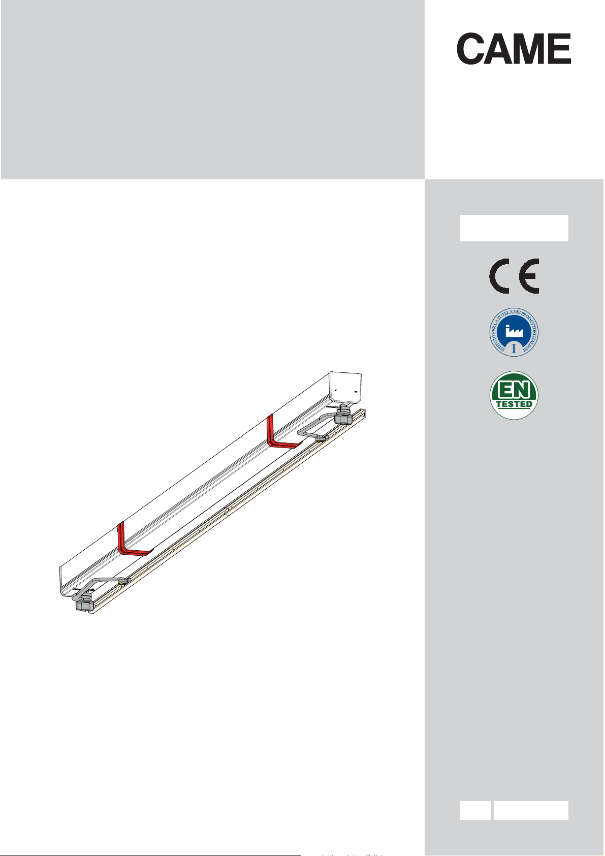
DESCRIPTION
This product has been designed and built by CAME S.p.A. in compliance with current legal safety standards.
The operator is composed of a part made of cast aluminium inside of which works the irreversible gearmotor plus an
aluminium casing.
The Sipario
The operators:
001VLR01DX
001VLR01SX
001VLR02 Irreversible operator for controlling two-leaf swing shutters, complete with control board and transmission-
The transmission arms:
001VLR07DX RIGHT-HAND curved transmission arm for single-panel shutters.
001VLR07SX LEFT-HAND curved transmission arm for single-panel shutters.
001VLR08DX Adjustable RIGHT-HAND curved transmission arm for shutters with single- or double-jointed panels.
001VLR08SX Adjustable LEFT-HAND curved transmission arm for shutters with single- or double-jointed panels.
001VLR09DX Adjustable RIGHT-HAND augmented curved transmission arm for shutters with double-jointed panels.
001VLR09SX Adjustable LEFT-HAND augmented curved transmission arm for shutters with double-jointed panels.
001VLR10DX RIGHT-HAND augmented curved transmission arm for single-panel shutters.
001VLR10SX LEFT-HAND augmented curved transmission arm for single-panel shutters.
The optional accessories:
001VLR04 Covering cross-piece for the VLR02 with light bays greater than 970 mm.
001VLR05 Emergency operation device, complete with 12 V batteries and battery-charging card.
RIGHT-HAND irreversible OPERATOR for controlling one-leaf swing shutters, complete with control board
and transmission-arm guide.
LEFT-HAND irreversible OPERATOR for controlling one-leaf swing shutters, complete with control board and
transmission-arm guide.
arm guides.
Intended use
The VOILA operator is designed for opening and closing one or two-leaf swing leaves.
By shutters we mean
Any installation and use other than that specified in this manual is forbidden.
Limits to use
Model VLR01DX - VLR01SX VLR02
Max. leaf width (m) 1.05 2.1
Maximum gate-leaf weight (kg) 35 35
2 - 01/2017 - © Came S.p.A . - The contents of this manual may be changed, at any time, and without notice.
FA00135-EN - vers.
4 - Manual code
Page
Page 5

5
FA00135-EN
2
Technical data
Type VLR01DX - VLR01SX VLR02 command
Protection rating (IP) 44 44
Power supply (V - 50/60 Hz) 230 AC 230 AC
Motor power supply (V) 24 DC 24 DC
Current draw (A) 3 max 6 max
Power (W) 75 150
Opening time at 180° (s) Adjustable Adjustable
Duty cycle (%) Intensive duty Intensive duty
Torque (Nm) 33 2 x 33
Working temperature (°C) -20 to +55 -20 to +55
Dimensions
VLR02 + VLR04
маx. 2090
85
VLR01DX
77
1040
70
VLR01SX
1040
37
VLR07SX VLR07DX
VLR08SX VLR08DX
114
2 - 01/2017 - © Came S.p.A . - The contents of this manual may be changed, at any time, and without notice.
VLR09SX VLR09DX
FA00135-EN - vers.
VLR10SX VLR10DX
5 - Manual code
Page
Page 6
6
FA00135-EN
2
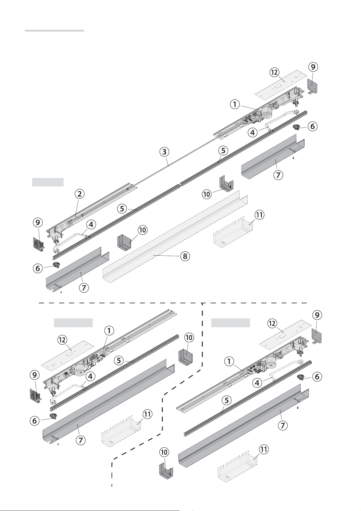
Description of parts
1. MASTER operator assembly: anchoring base/control board/transformer/gearmotor
2. SLAVE operator: anchoring base/gearmotor
3. Master/Slave connection cable
4. Transmission arms (see following tables)
5. Arm slide-guides
6. Manual release lever
7. Protective carter for operators
8. Continuous protective carter (OPTIONAL, item VLR04)
9. End caps
10. Carter closing/connecting strips
11. Emergency battery device (OPTIONAL, item VLR05)
12. Drilling template
VLR02
VLR01SX
VLR01DX
2 - 01/2017 - © Came S.p.A . - The contents of this manual may be changed, at any time, and without notice.
FA00135-EN - vers.
6 - Manual code
Page
Page 7

7
FA00135-EN
2
One or two-leaved single panel retractable shutter
Unfoldable type of transmission arm VLR07 VLR08
A - Minimum space between the inner fi xture and the
(without batteries / with VLR05 batteries)
B - Bay width (min./max.)
One leaf, without VLR01xx batteries
One leaf, with VLR01xx+VLR05 batteries
Two leaves, without VLR02 batteries
Two leaves with VLR02+VLR05 batteries
C - Recessing of outer edge (min./max.) 60 130 / 170
The angle
must always exceed 90°; install a simple strike plate for this.
shutter
90 / 110 130
500 / 1050
750 / 1050
720 / 2100
970 / 2100
500 / 1050
750 / 1050
820 / 2100
970 / 2100
One or two-leaf single-panel shutter, with outer edge
Unfoldable type of transmission arm VLR07 VLR08 VLR010
A - Minimum space between the inner fi xture and the
(without batteries / with VLR05 batteries)
B - Bay width (min./max.)
One leaf, without VLR01xx batteries
One leaf, with VLR01xx+VLR05 batteries
Two leaves, without VLR02 batteries
Two leaves with VLR02+VLR05 batteries
D - Hinge position beyond the bay (min./max.) 30 / 40 30 / 90 0 / 60
E - Hinge position beyond the outer edge (min./max.) 25 / 40 30 / 100 -
The angle
2 - 01/2017 - © Came S.p.A . - The contents of this manual may be changed, at any time, and without notice.
must always exceed 90°; install a simple strike plate for this.
shutter
90 / 110 130 165
500 / 1050
750 / 1050
720 / 2100
970 / 2100
500 / 1050
750 / 1050
820 / 2100
970 / 2100
500 / 1050
750 / 1050
720 / 2100
970 / 2100
FA00135-EN - vers.
7 - Manual code
Page
Page 8

8
FA00135-EN
2
One or two-leaved jointed double-paneled shutter
Unfoldable type of transmission arm VLR08 VLR09
A - Minimum space between the inner fi xture and the
shutter
130 160
B - Bay width (min./max.)
One leaf, without VLR01xx batteries
One leaf, with VLR01xx+VLR05 batteries
Two leaves, without VLR02 batteries
Two leaves with VLR02+VLR05 batteries
500 / 1050
750 / 1050
820 / 2100
970 / 2100
500 / 1050
750 / 1050
900 / 2100
970 / 2100
F - Width of internal panel (min./max.) 140 / 170 170 / 240
The angle
For this application, fi t a corner protection
must always exceed 90°; install a simple strike plate for this.
for the arm.
GENERAL INSTRUCTIONS FOR INSTALLING
Installation must be carried out by expert qualified personnel and in full compliance with the regulations in force.
⚠
Preliminary checks
• Check that the operator fixing point is protected from possible knocks, and that the fixing surface is solid. Also check that
appropriate screws, plugs, etc. are used to fix the panel;
• Set up suitable conduits and tubes to safely run the electrical cables through and to protect them from mechanical damage.
• Remove the shutter opening stops and replace them with strike plates.
• Make sure the angles between the two leaves always exceeds 90°.
Tools and materials
Make sure you have all the tools and materials you will need for installing in total
safety and in compliance with applicable regulations. The figure shows some of the
equipment installers will need.
Cable types and minimum thicknesses
Connection Cable type Cable length
1 < 10 m 10 < 20 m 20 < 30 m
Power supply to control panel 230 V
Accessories powered at 24 V 2 x 0.5 mm
Command and safety device 2 x 0.5 mm
Home & building automation connections CAT5 - U/UTP - AWG24 max 1200 m
FROR CEI 20-22
CEI EN 50267-2-1
3G x 1.5 mm23G x 2.5 mm
2
2 x 0.5 mm
2
2 x 0.5 mm
2
2
2
3G x 4 mm
2 x 1 mm
2 x 0.5 mm
2
2
2
2 - 01/2017 - © Came S.p.A . - The contents of this manual may be changed, at any time, and without notice.
FA00135-EN - vers.
If the cable lengths differ from that specified in the table, then you must determine the cable diameter based on the actual
☞
power draw from the connected devices and according to the CEI EN 60204-1 standard.
For multiple, sequential loads along the same line, the dimensions on the table need to be recalculated according to the actual
power draw and distances. For connecting products that are not contemplated in this manual, see the literature accompanying
said products
8 - Manual code
Page
Page 9

9
FA00135-EN
2
INSTALLING
The following illustrations are examples. It is up to the installer to find the most suitable solution.
The template features the indications for use on both the right and left.
Tracing the holes
Rest the template against the shutters and the bay side
panel of the bay and mark the holes using a pencil; finish
marking out the holes ❶ on the metal anchoring base of the
Voilà unit.
So, drill for using suitable fasteners.
For laying the cables, see details on page 14; zone
shows the cable entry point, in option 1.
2 - 01/2017 - © Came S.p.A . - The contents of this manual may be changed, at any time, and without notice.
❷
FA00135-EN - vers.
9 - Manual code
Page
Page 10

10
FA00135-EN
2
Fastening the operator
If the bay width is less than the dimensions of the operator base(s), cut off any excess ❸. The emergency batteries
(item VLR05) may not be fitted.
Fit the operator using suitable screws and dowels.
For the two-leaf swing configuration, install the MASTER
Fitting the transmission arms and the slide rails
operator
the left.
❹ on the right and the SLAVE operator ❺ on
Before fitting the transmission arm, lubricate the motor
shaft thread.
Fit the arm (also see detail
the motor shaft.
Leave the lever loose so as to make it easier to insert
the arm skid in the slide guide.
) and the release lever on
2 - 01/2017 - © Came S.p.A . - The contents of this manual may be changed, at any time, and without notice.
The VLR08 and VLR09 arms
need to be preassembled with a
loosened screws, for subsequent
adjustment.
Always use all three of the
screws supplied.
FA00135-EN - vers.
10 - Manual code
Page
Page 11

11
FA00135-EN
2
Cut the slide rails to the required length, leaving a minimum clearance at the ends.
One or two-leaf single-panel shutter One or two-leaved jointed double-paneled shutter
Fit the arm skid into the slide rail
(see ).
Fit the guide to the shutter and
check that it is level and that the
skid slides smoothly.
Use the premarked holes and
use flat countersunk screws (not
issued).
2 - 01/2017 - © Came S.p.A . - The contents of this manual may be changed, at any time, and without notice.
The operation should be
performed with the transmission
arm fixed to the motor shaft.
FA00135-EN - vers.
The VLR08/VLR09 adjustable arms, allow you to adjust the leaf opening more accurately, by changing the joining holes of the
two semi-arms (see page 10, figure ).
11 - Manual code
Page
Page 12

1÷2
0
12
FA00135-EN
2
VLR02 operator Master and Slave connection
Attach the cable clips ❻.
Connect the Slave gearmotor to the Master operator using the wired cable❼ on the MOTOR1 terminal.
In this way, the right-hand leaf will open first.
If you need the left-hand leaf to open first while keeping the Master to the right, swap the MOTOR1 and
MOTOR2 connectors.
Manual release of the operator
Activating the manual release could result in the shutter moving inadvertently due to possible mechanical failures or
balance issues.
2 - 01/2017 - © Came S.p.A . - The contents of this manual may be changed, at any time, and without notice.
FA00135-EN - vers.
12 - Manual code
Page
Page 13

13
FA00135-EN
2
ELECTRICAL CONNECTIONS AND PROGRAMMING
The control panel is powered by 230 V AC, with 50/60Hz frequency. The control devices and accessories run on 24 V.
The accessories must never exceed 15 W in total.
⚠
Fuses
Type
Line (mA) 400
Accessories (mA) 630
Description of parts
1. 230 V AC power-supply terminals
2. Transformer connection terminals
3. Line fuse
4. Accessories fuse
5. 24 V power-supply terminals for
control and safety devices
6. CRP connection terminals
7. AF card connector
8. RSE board connector
9. Built-in antenna
③ ④ ⑤⑮
L N
①
210 411CX3
10. DIP-switch for selecting functions with RSE
11. Programming button
12. Battery-charger connector
13. MOTOR 1 and MOTOR 2 sockets
14. Power on signalling LED
15. Programming warning LED
16. Dip-switches for selecting functions and programming
⑥ ⑦ ⑧ ⑨
BAGND
⑩
⑭
L1TL2T
2 - 01/2017 - © Came S.p.A . - The contents of this manual may be changed, at any time, and without notice.
②
Power supply
FA00135-EN - vers.
13 - Manual code
Page
20V
0V
L N
J8
M1
J7
M3
630mA-F
ACCESSORIES
11
⑬
2 10 4
R9
R25
C13
C23
CH1
⑪
Terminals for powering 24 V AC accessories.
Maximum allowed power: 15 W.
CX 3
R22 R23
B A GND
M6
R3
R6
C17
C11 C12
⑫
⑯
Page 14

14
FA00135-EN
2
There are two possible points to pass the power-supply and accessory-control cables through: either on the anchoring base
through the existing slots (option 1), or on the end cap which features pre-shaped apertures (option 2).
Connect the ground to both gearmotors.
Option 1 Option 2
Command and control devices
The AF and RSE cards must be fitted
into the control board AFTER CUTTING
OFF THE MAINS POWER.
N.B.: the basic control board recognises
them only when it is powered up.
LEFT-HAND MOTOR
RSE card
RIGHT-HAND MOTOR
GND
B
A
CX3
210 4
11
CRP - Came Remote Protocoll.
Connection to the home-automation
system.
AF card
B A GND
M6
OPEN-STOP function (NO contact)
LINE 1A-F
CLOSE-STOP function (NO contact)
⚠ If the PARTIAL OPENING function is activated via a dip-switch on the button connected to 2-3, then the button connected
to 2-4 will automatically operate as a sequential OPEN-STOP-CLOSE-STOP command.
⚠ If MAINTAINED ACTION is activated via dip-switches, the two buttons will operate as automatically OPEN and CLOSE,
respectively.
⚠When the MAINTAINED ACTION function is active, the PARTIAL OPENING function cannot be set.
2 - 01/2017 - © Came S.p.A . - The contents of this manual may be changed, at any time, and without notice.
FA00135-EN - vers.
14 - Manual code
Page
Page 15

15
FA00135-EN
2
Safety devices
REOPENING DURING CLOSING (NC). During the leaf closing phase, opening the contact inverts the movement until the leaves
are fully open.
TX
TX
2 NC C TX 2 10
If contacts 2-CX are unused,
they should be bridged.
L N
LINE 1A-F
L1TL2T
20V
0V
001AF43S - 001AF868 card fitting
210 411CX3
BAGND
C23
CH1
2 - 01/2017 - © Came S.p.A . - The contents of this manual may be changed, at any time, and without notice.
FA00135-EN - vers.
15 - Manual code
Page
AF card
Page 16

16
FA00135-EN
2
Programming the features
Before programming functions, release the gearmotors, manually close the shutter leaves and re-lock the gearmotors.
DIP1 DIP2 DIP3 DIP4 Description of functions
ON ON ON OFF Self-learning of the gate-leaf travel
OFF OFF OFF ON Partial opening from button
ON OFF OFF ON Button-activated maintained action
ON OFF OFF OFF Transmitter activated partial opening
OFF ON OFF OFF OPEN-STOP from trasmitter
ON ON OFF OFF CLOSE-STOP from transmitter
OFF OFF ON OFF Transmitter activated OPEN-STOP-CLOSE-STOP
ON OFF ON OFF Weather unit
OFF ON ON OFF Deleting memorized transmitters and weather units
OFF ON OFF ON Increasing the maneuvering speed
ON ON OFF ON Reducing the slow-down speed
OFF OFF ON ON Adjusting the sensitivity
ON OFF ON ON Slowed-down start when closing
OFF ON ON ON Immediate closing in case of a power outage
ON ON ON ON Resetting parameters
Self-learning of the gate-leaf travel
Select the DIPs as shown and press the PROG key on the
board.
To calibrate the travel the leaves must be closed.
The leaves will perform a series of maneuvers to establish the
limit switch points.
During calibration the red LED flashes. Once the calibration is
To disable the function: with the DIP switches set as shown,
press again the PROG key on the control boar.
Button-activated maintained action
Select the DIP switches as shown or press PROG on the
control board.
Once memorized the buzzer sounds off for one second.
done the buzzer sounds off for one second.
To restore the default parameters press
If calibration was not successful, the LED flashes quickly and
the buzzer sounds 4 times.
The self-learning procedure can be interrupted
by pressing the PROG key .
To configure for one swing-leaf, connect the operator to
⚠
MOTOR2.
Partial opening from button
Use the buttons to move the leaves to the desired position
Only consider the first leaf's opening angle. During the first
maneuver, the second leaf will memorize the opening angle
PROG again. The LED flashes and the buzzer sounds off
twice.
The opening button connected to 2-3 (NO contact) is
⚠
default set to the OPEN-STOP function.
If I enable maintained action from a button, I cannot enable
partial opening from a button and neither from a transmitter.
You can memorize up to a maximum of ten different
radio codes.
Partial opening using transmitter (only if already saved to
a button).
of the first leaf.
Select the DIP switches as shown or press PROG on the
Select the DIP switches as shown or press PROG on the
control board.
Once memorized the buzzer sounds off for one second.
control board. The red LED flashes. Within ten seconds press
the button on the transmitter you wish to memorize. Once
memorized the buzzer sounds off for one second.
2 - 01/2017 - © Came S.p.A . - The contents of this manual may be changed, at any time, and without notice.
FA00135-EN - vers.
If the partial opening angle does not come within the
minimum and maximum default-set limits (fro 10% to 50%
of the travel), upon sending the next command the opening
angle will automatically set to the closest level.
If the key has already been memorized, the LED will flash
quickly and buzzer will flash four times.
16 - Manual code
Page
Page 17

17
FA00135-EN
2
OPEN-STOP from transmitter
Select the DIP switches as shown or press PROG on the
control board. The red LED flashes. Within ten seconds press
the button on the transmitter you wish to memorize.
control board. The LED stays on and the buzzer sounds off
for 1 s.
To return to the default settings, press the PROG key again.
The LED flashes and the buzzer sounds off twice.
Once memorized the buzzer sounds off for one second.
If the key has already been memorized, the LED will flash
quickly and buzzer will flash four times.
CLOSE-STOP from transmitter
Select the DIP switches as shown or press PROG on the
control board. The red LED flashes. Within ten seconds press
the button on the transmitter you wish to memorize.
Once memorized the buzzer sounds off for one second.
If the key has already been memorized, the LED will flash
quickly and buzzer will flash four times.
Transmitter activated OPEN-STOP-CLOSE-STOP
Select the DIP switches as shown or press PROG on the
control board. The red LED flashes. Within ten seconds press
the button on the transmitter you wish to memorize.
Once memorized the buzzer sounds off for one second.
If the key has already been memorized, the LED will flash
quickly and buzzer will flash four times.
Weather unit
The weather unit occupies 3 radio codes.
⚠
Select the DIP switches as shown or press PROG on the
control board. The red LED flashes. Within ten seconds press
the P2 key on the weather unit. Once memorized the buzzer
sounds off for one second.
If the weather unit has already been memorized, the LED will
flash quickly and the buzzer will sound off four times.
Deleting memorized transmitters and weather units
Select the DIP-switches as shown and press PROG on the
control board for five seconds.
After deleting, the red LED flashes and the buzzer sounds off
for one second.
Adjusting the sensitivity
The default obstruction-intervention time is one second.
To increase the intervention time to two seconds:
Select the DIP switches as shown or press PROG on the
control board. The LED stays on and the buzzer sounds off
for 1 s.
To return to the default parameters, press PROG again. The
LED flashes and the buzzer sounds off twice.
Slowed-down start when closing
The slow-down is disabled by default.
To enable it:
Select the DIP switches as shown or press PROG on the
control board. The LED stays on and the buzzer sounds off
for 1 s.
To return to the default parameters, press PROG again. The
LED flashes and the buzzer sounds off twice.
Immediate closing in case of a power outage
This function can be used only where there are batteries.
⚠
To enable it:
Select the DIP switches as shown or press PROG on the
control board. The LED stays on and the buzzer sounds off
for 1 s.
To return to the default parameters, press PROG again. The
LED flashes and the buzzer sounds off twice.
Resetting parameters
Once reset, the LED flashes and the buzzer sounds off twice.
With this function the transmitters and weather unit are not
deleted.
Increasing the maneuvering speed
The default maneuvering speed is set to 70%.
To increase the maneuvering speed by 20%:
Select the DIP switches as shown or press PROG on the
2 - 01/2017 - © Came S.p.A . - The contents of this manual may be changed, at any time, and without notice.
control board. The red LED stays lit and buzzer sounds off
for one second.
To return to the default settings, press the PROG key again.
The LED flashes and the buzzer sounds off twice.
Reducing the slow-down speed
FA00135-EN - vers.
The default maneuvering speed is set to 50%.
To reduce the slow-down speed by 10%:
Select the DIP switches as shown or press PROG on the
17 - Manual code
Page
Page 18

18
FA00135-EN
2
FINAL OPERATIONS
Fasten the end caps using the supplied screws.
Fit the snap-in casing onto the gearmotor and secure it using the
supplied screws.
With two-leaved installations like with the Voilà VLR02, whose window-bay width exceeds 970 mm, we suggest also fitting
the VLR04 covering cross-piece so that it also covers the Master/Slave connection.
After reducing it to the right size (L1 = L - 14 mm), snap it into the guides and cover the joints using suitably modified strips
with the end caps removed.
2 - 01/2017 - © Came S.p.A . - The contents of this manual may be changed, at any time, and without notice.
FA00135-EN - vers.
18 - Manual code
Page
Page 19

19
FA00135-EN
2
DISMANTLING AND DISPOSAL
CAME S.p.A. applies a certified Environmental Management System at its premises, which is compliant with the UNI EN
☞
ISO 14001 standard to ensure environmental protection.
Please continue safeguarding the environment. At CAME we consider it one of the fundamentals of our operating and market
strategies. Simply follow these brief disposal guidelines:
DISPOSING OF THE PACKAGING
The packaging materials (cardboard, plastic, and so on) should be disposed of as solid household waste, and simply
separated from other waste for recycling.
Always make sure you comply with local laws before dismantling and disposing of the product.
DISPOSE OF RESPONSIBLY!
DISPOSING OF THE PRODUCT
Our products are made of various materials. Most of these (aluminium, plastic, iron, electrical cables) are classified as solid
household waste. They can be recycled by separating them before dumping at authorized city plants.
Whereas other components (control boards, batteries, transmitters, and so on) may contain hazardous pollutants.
These must therefore be disposed of by authorized, certified professional services.
Before disposing, it is always advisable to check with the specific laws that apply in your area.
DISPOSE OF RESPONSIBLY!
DECLARATION OF CONFORMITY
This product complies with the law.
2 - 01/2017 - © Came S.p.A . - The contents of this manual may be changed, at any time, and without notice.
FA00135-EN - vers.
19 - Manual code
Page
Page 20

www. came.com
CAME S.p.A.
Dosson di Casier
Treviso
Sesto al Reghena
Pordenone
English
FA00135-EN
2
2 - 01/2017 - © Came S.p.A .
FA00135-EN - vers.
The data and information in this manual are susceptible to changes at any time and without prior notice
English - Manual code
CAME S.p.A.
Via Martiri Della Libertà, 15 Via Cornia, 1/b - 1/c
31030
Dosson di Casier
Treviso - Italy
(+39) 0422 4940
(+39) 0422 4941
www. came.com
33079
Pordenone - Italy
Sesto al Reghena
(+39) 0434 698111
(+39) 0434 698434
 Loading...