

Page 1
SERIE VER |
VER
SERIES
|
SÉRIE VER |
BAUREIHE
VER |
SERIE VER
Documentazione
Tecnica
S90
rev. 0.9
02/2003
©
CAME
CANCELLI
AUTOMATICI
CANCELLI AUTOMATICI
V600E
Automazione con sistema a traino per porte basculanti e sezionali
Automatic traction system for overhead and sectional doors
Automatisme avec systéme "a traction" pour portes basculantes et sectionnels
Schubantriebssistem für Schwing-und Sektionaltore
Automatización con sistema "por arrastre" para puertas basculantes y seccionales
119ES90
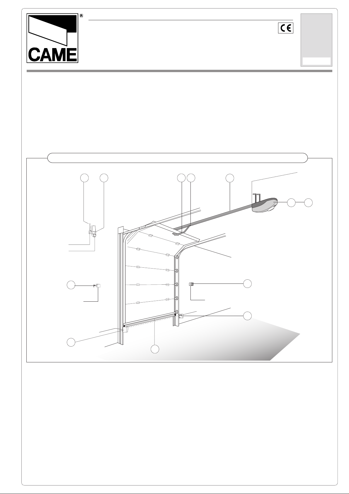
Impianto tipo -
9 10 7 8
T RG58
2x1,5
11
2x1
5
Standard installation -
4x1
RX
Installation type
2x1
TX
6
- Standard Montage -
1
6x1,5
Instalaciòn tipo
230V~
3x1,5
2 3
4
5
1. Gruppo VER
2. Quadro comando incorporato
3. Ricevitore radio
4. Pulsantiera da interno
5. Fotocellule di sicurezza
6. Costola a raggi infrarossi
7. Braccio di trasmissione
8. Dispositivo di sblocco
9. Antenna
10. Lampeggiatore
11. Selettore a chiave
1. VER unit
2. Incorporated control
panel
3. Radio receiver
4. Internal pushbutton array
5. Safety photocells
6. Infrared rib
7. Transmission arm
8. Release mechanism
9. Antenna
10. Flashing light
11. Key-operated selector
switch
1. Groupe VER
2. Armoire de commande
incorporée
3. Récepteur radio
4. Poussoirs internes
5. Photocellules de
sécurité
6. Profil de sécurité à
rajons infrarouges
7. Bras de transmission
8. Dispositif de déblocage
9. Antenne
10. Clignotant
11. Sélecteur à clé
1. VER-Antriebsmotor
2. Intergrierte motor-
steuerung
3. Funkempfänger
4. Schalteinheit für Innen-
montage
5. Lichtschanken
6. Infrarot Sicherheitsleiste
7. Antriebsarm
8. Entriegelungssjstem
9. Antenne
10. Blinkleuche
11. Schlüsselschalter
1. Conjunto VER
2. Cuadro de mando
incorporado
3. Radiorreceptor
4. Botonera interior
5. Fotocélulas de seguridad
6. Protector por infrarrojos
7. Brazo de transmisión
8. Dispositivo de desbloqueo
9. Antena
10. Lámpara intermitente
11. Selector a llave
Page 2

ITALIANO
- Automazione a traino per porte basculanti e sezionali;
- Progettato e costruito interamente dalla CAME Cancelli Automatici
S.p.A., risponde alle vigenti norme di sicurezza;
- Grado di protezione IP 40;
- Garantito 24 mesi salvo manomissioni.
V600E
Motoriduttore 24V (D.C.) con controllo a Encoder e con quadro
comando incorporato; alimentazione a 230V a.c. con frequenza
50÷60Hz; potenza motore 130W max e forza di trazione fino a 500N;
V0671 - V0674
Gruppo guida con catena L = 3,02 m (V0674 = guida in due metà da
assemblare a 3,02 m);
- per porte basculanti a contrappesi fino a 2,40 m di altezza
- per porte basculanti a molle fino a 2,25 m di altezza
- per porte sezionali* fino a 2,20 m di altezza
V0672
Gruppo guida con catena L = 3,52 m;
- per porte basculanti a molle fino a 2,75 m di altezza
- per porte sezionali* fino a 2,70 m di altezza
V0673
Gruppo guida con catena L = 4,02 m;
- per porte basculanti a molle fino a 3,25 m di altezza
- per porte sezionali* fino a 3,20 m di altezza
V0675 - V0678
Gruppo guida con cinghia L = 3,02 m (V0678 = guida in due metà da
assemblare a 3,02 m);
- per porte basculanti a contrappesi fino a 2,40 m di altezza
- per porte basculanti a molle fino a 2,25 m di altezza
- per porte sezionali* fino a 2,20 m di altezza
V0676
Gruppo guida con cinghia L = 3,52 m;
- per porte basculanti a molle fino a 2,75 m di altezza
- per porte sezionali* fino a 2,70 m di altezza
V0677
Gruppo guida con cinghia L = 4,02 m;
- per porte basculanti a molle fino a 3,25 m di altezza
- per porte sezionali* fino a 3,20 m di altezza
Caratteristiche
Descrizione generale:
Versioni:
Guide di traino:
* vedi pagina 5
Accessori di completamento:
V201
Braccio adattatore di trasmissione per porte basculanti a contrappeso
(sostituisce quella in dotazione), vedi pag.7;
Accessori opzionali:
V0670
Scheda collegamento batterie d'emergenza, completa di supporto per
2 batterie (12V-1,2Ah -
V121
Dispositivo di sblocco a cordino e rinvio per il collegamento alla serratura;
V122
Braccio di trasmissione maggiorato per portoni sezionali, vedi pag.6;
- Motoriduttore alimentato a 24V in corrente continua (d.c.); cassa del
riduttore in alluminio pressofuso al cui interno opera un sistema di riduzione irreversibile a vite senza fine e corona elicoidale. La lubrificazione è a
grasso fluido permanente.
- Contenitore automazione in ABS con coperchio provvisto di finestra per
lampada di illuminazione diffusa dell'ambiente. Il gruppo è montato e sostenuto dalla guida di trascinamento.
- Quadro elettrico di comando incorporato.
- Finecorsa a gestione elettronica (Encoder);
- Guida di trascinamento in lamiera zincata profilata a freddo; terminale
anteriore di tensionamento e di fissaggio alla parete; terminale posteriore in
ABS di innesto e sostegno gruppo motore. La guida incorpora il dispositivo di sblocco d'emergenza e l'aggancio del braccio di trasmissione; nella
guida sono previste delle forature per eventuali attacchi delle staffe supplementari.
- Sistema di traino a catena o a cinghia.
ESCLUSE
Caratteristiche tecniche:
);
ENGLISH
- Automatic traction system for overhead and sectional doors;
- Designed and built entirety by CAME Cancelli automatici S.p.A., in full
compliance with current safety standards;
- IP 40 protecting rating;
- Guaranteed for 24 months, unless tampered with by unauthorized
personnel.
V600E
Encoder controlled 24V (D.C.) gearmotor with built-in control panel;
230V AC power with 50÷60Hz frequency; 130W max. motor power and
up to 500N in traction power.
V0671 - V0674
Rail unit with chain L = 3,02 m (V0674 = rail unit in two halves to
assemble at 3.02 m);
- for counterweighted overhead doors up to 2,40 m height
- for spring-balanced overhead doors up to 2,25 m height
- for sectional doors* up to 2,20 m height
V0672
Rail unit with chain L = 3,52 m;
- for spring-balanced overhead doors up to 2,75 m height
- for sectional doors* up to 2,70 m height
V0673
Rail unit with chain L = 4,02 m;
- for spring-balanced overhead doors up to 3,25 m height
- for sectional doors* up to 3,20 m height
V0675 - V0678
Rail unit with belt L = 3,02 m (V0678 = rail unit in two halves to
assemble at 3.02 m);
- for counterweighted overhead doors up to 2,40 m height
- for spring-balanced overhead doors up to 2,25 m height
- for sectional doors* up to 2,20 m height
V0676
Rail unit with belt L = 3,52 m;
- for spring-balanced overhead doors up to 2,75 m height
- for sectional doors* up to 2,70 m height
V0677
Rail unit with belt L = 4,02 m;
- for spring-balanced overhead doors up to 3,25 m height
- for sectional doors* up to 3,20 m height
Caracteristics
General description:
Versions:
Sliding rails:
* see page 5
Accessori di completamento:
V201
Transmission adapter arm for counterweighted overhead doors (it
substitutes the arm supplied), see pg. 7;
Optional accessories:
V0670
Emergency battery connection card with suppor t for 2 batteries (12V1,2Ah
- ESCLUSE
V121
Cable release device and transmission for connection to the lock;
V122
Improved transmissionarm for sectional gates, see pg. 6;
- 24V DC gear motor; reduction gear unit housed in a die-cast aluminium
casing. The unit features an irreversible reduction gear with worm screw
and helicoidal. Permanently lubricated with liquid grease.
- ABS automation container and cover with window for lamp to illuminate
the area. The unit is mounted on and supported by the sliding rail.
- Built-in electric control panel.
- Electronically run (Encoder) end-stop;
- Galvanised cold-formed plate sliding rail; front tensioning and fastening
wall terminal; ABS back motor unit support and connector terminal. The rail
has a built-in emergency release device and the transmission arm’s hook;
the rail has holes for possible connection of additional brackets.
- Chain or belt sliding system.
Attention! to insure easy installation and conformance with current safety,
norms, we raccomend installation of CAME safety and control accessories.
);
Technical specifications:
Attenzione! Controllate che le apparecchiature di comando, di sicurezza e gli
accessori siano originali CAME; ciò garantisce e rende l'impianto di facile
esecuzione e manutenzione.
2
Page 3

FRANÇAIS
Description génèralés:
- Automatisme avec sistéme "a traction" pour portes basculantes et sectionnels.
- Il a été entièrement concu et construit par la Société CAME Cancelli
Automatici S.p.A., conformément aux normes de sécurité en vigueur;
- Degré de protection IP 40.
- Il est garanti 24 mois sauf en cas d'altérations.
Versioni:
V600E
Motoréducteur 24V (D.C.) avec contrôle par encodeur et tableau de
commande incorporé; alimentation en 230V a.c. avec fréquence 50÷60Hz;
puissance du moteur 130W max. et force de traction jusqu’à 500N;
Guides de traction:
V0671 - V0674
Groupe guide avec chaîne L = 3,02 m (
moitiés à assembler à 3,02 m);
- pour portes basculantes à contrepoids jusqu’à 2,40 m de haut
- pour portes basculantes à ressorts jusqu’à 2,25 m de haut
- pour portes sectionnelles*
V0672
Groupe guide avec chaîne L = 3,52 m;
- pour portes basculantes à ressorts jusqu’à 2,75 m de haut
- pour portes sectionnelles*
V0673
Groupe guide avec chaîne L = 4,02 m;
- pour portes basculantes à ressorts jusqu’à 3,25 m de haut
- pour portes sectionnelles*
V0675 - V0678
Groupe guide avec courroie L = 3,02 m (
moitiés à assembler à 3,02 m);
- pour portes basculantes à contrepoids jusqu’à 2,40 m de haut
- pour portes basculantes à ressorts jusqu’à 2,25 m de haut
- pour portes sectionnelles*
V0676
Groupe guide avec courroie L = 3,52 m;
- pour portes basculantes à ressorts jusqu’à 2,75 m de haut
- pour portes sectionnelles*
V0677
Groupe guide avec courroie L = 4,02 m;
- pour portes basculantes à ressorts jusqu’à 3,25 m de haut
- pour portes sectionnelles*
jusqu’à
jusqu’à
jusqu’à
jusqu’à
jusqu’à
jusqu’à
* voir page 5
Accessoires complémentaires:
V201
Bras adaptateur de transmission pour portes basculantes à contrepoids
(remplace celui fourni de série), voir page 7;
Accessoires en option:
V0670
Carte de branchement batteries d’urgence avec support pour 2 batteries
(12V-1,2 Ah –
V121
Dispositif de déblocage et de renvoi à cordon pour le branchement à la
serrure;
V122
Bras de transmission plus grand pour portes sectionnelles, voir p. 6;
Motoréducteur alimenté en 24V en courant continu (d.c.); coffre du réducteur réalisé
en aluminium moulé sous pression. A l'intérieur agi' un système de réduction irréversible
à vis sans fin et couronne hélicoidale. Lubrification permanente par graisse fluide.
Boîtier automatisme en ABS avec couvercle muni d’une fenêtre pour lampe d’éclairage
diffuse du local. Le groupe est monté et soutenu par le guide d’entraînement.
Tableau électrique de commande incorporé.
Fin de course à gestion électronique (Encoder);
-
Guide d’entraînement en tôle zinguée profilée à froid; élément terminal avant de
-
tension et de fixation au mur; élément terminal arrière de raccord et de soutien du
groupe du moteur en ABS. Le guide comprend le dispositif de déblocage d’urgence et
d’accrochage du bras de transmission; des trous ont été prévus dans le guide pour les
raccords éventuels des brides supplémentaires.
Système de traction par chaîne ou par courroie.
-
Attention! Vérifiez que l'appareillage de commande, de sécurité et les accessoires sont
des produits originaux CAME afin de garantir l'installation et d'en faciliter le montage
et l'entretien.
NON COMPRISES
Caractéristiques techniques:
V0674 = groupe guide en deux
2,20 m de haut
2,70 m de haut
3,20 m de haut
V0678 = groupe guide en deux
2,20 m de haut
2,70 m de haut
3,20 m de haut
);
DEUTSCH
- Schubantriebssistem für Kipptoren und Sektionaltoren.
- Vollständig von der CAME Cancelli Automatici S.p.A. gemäß geltender
Sicherheilsnormen entwickelt und hergestellt.
- Schutzklasse IP 40;
- Garantie: 24 Monate, vorbehaltlich unsachgemäßer Handhabung und
Montage.
V600E
Getriebemotor 24V (Gleichstrom) mit Encoder-Kontrolle und eingebauter
Schalttafel; Speisung 230V WS mit Frequenz 50-60 Hz; max. Motorleistung
130W und Zugkraft bis zu 500N;
V0671 - V0674
Steuergruppe mit Kette L = 3.02 m (
ten auf 3.02 m zusammenzusetzen);
- für Gegengewicht-Kipptoren bis zu einer Höhe von 2.40 m
- für Ausgleichsfeder-Kipptoren bis zu einer Höhe von 2.25 m
- für Sektionaltoren*
V0672
Steuergruppe mit Kette L = 3.52 m;
- für Ausgleichsfeder-Kipptoren bis zu einer Höhe von 2.75 m
- für Sektionaltoren*
V0673
Steuergruppe mit Kette L = 4.02 m;
- für Ausgleichsfeder-Kipptoren bis zu einer Höhe von 3.25 m
- für Sektionaltoren*
V0675 - V0678
Steuergruppe mit Riemen L = 3.02 m (
Hälften auf 3.02 m zusammenzusetzen);
- für Gegengewicht-Kipptoren bis zu einer Höhe von 2.40 m
- für Ausgleichsfeder-Kipptoren bis zu einer Höhe von 2.25 m
- für Sektionaltoren*
V0676
Steuergruppe mit Riemen L = 3.52 m;
- für Ausgleichsfeder-Kipptoren bis zu einer Höhe von 2.75 m
- für Sektionaltoren* zu einer Höhe von 2,70 m
V0677
Steuergruppe mit Riemen L = 4.02 m;
- für Ausgleichsfeder-Kipptoren bis zu einer Höhe von 3.25 m
- für Sektionaltoren*
Allgemeine merkmaleCaractéristiques
Beschreibung:
Ausführungen:
Antriebsgehäuse:
V0674 = Steuergruppe in zwei Hälf-
bis
zu einer Höhe von 2,20 m
bis
zu einer Höhe von 2,70 m
bis
zu einer Höhe von 3,20 m
bis
zu einer Höhe von 2,20 m
bis
zu einer Höhe von 3,20 m
V0678 = Steuergruppe in zwei
* siehe Seite 5
Zusätzliche Zubehörteile:
V201
Anpassungs-Antriebsarm für Gegengewicht-Kipptoren (ersetzt den zur
Ausstattung gehörenden Arm), siehe Seite 7;
Optionale Zubehörteile:
V0670
Anschlußkarte für Notbatterien mit Halterung für 2 Batterien (12V-1,2Ah
AUSGESCHLOSSEN);
–
V121
Entsperrvorrichtung mit Schnur und Umlenkung zur Verbindung mit
dem Schloß;
V122
Übergroßer Antriebsarm für Sektionaltoren, siehe Seite 6;
Technische Eigenschaften:
- In Gleichstrom (d.c.) bei 24V gespeister
Aluminium-druckgußgehäuse. Irreversibles Schnecken/
Schrägzahnraduntersetzungsgetriebe. Dauerschmierung mirreis flüssigem Schmiermittel.
Kasten für die Automatik in ABS mit einem mit einem Fenster versehenen Deckel für
die Lampe zur Beleuchtung der Umgebung. Die Gruppe ist montiert und durch den
Verbindungsträger abgestützt.
- Eingebaute
Endanschlag mit elektronischer Überwachung (Encoder)
Verbindungsträger aus kaltgeformten Zinkblech; vorderes Endstück zum Spannen
-
und zur Wandbefestigung; hinteres Endstück in ABS zur Kupplung und Halterung der
Motorgruppe. In der Steuergruppe ist die Notentsperrvorrichtung und die Kupplung
des Antriebsarms eingebaut; in der Steuergruppe sind Bohrungen für die eventuellen
Anschlüsse von zusätzlichen Bügeln vorgesehen.
Zugsystem durch Kette oder Riemen
Achtung! Wir empfehlen original CAME-Schalt- und -Sicherheitsvorrichtungen mit
entsprechendem Zubehör zu montieren, um die einwandfreie Montage und die
problemlose Wartung der Anlage zu gewährleisten.
Schalttafel.
Getriebemotor; Untersetzungsgetriebe in
3
Page 4
ESPAÑOL
Caracteristicas
Descripción generales:
- Automatización con sistema "por arrastre" para puertas basculantes
y seccionales.
- Diseñado y fabricado enteramente por CAME Cancelli Automatici
S.p.A., cumple con las normas de seguridad vigentes.
- Grado de protección IP 40.
- Garantizado 24 meses, salvo manipulaciones.
Versiones:
V600E
Motorreductor 24V (D.C.) con control por Encoder y con cuadro de
mando incorporado; alimentación a 230V c.a. con frecuencia 50÷60Hz;
potencia motor 130W máx. y fuerza de tracción hasta 500N;
Guías de empuje:
V0671 - V0674
Grupo de guía con cadena L = 3,02 m (V0674 = grupo de guía en dos
mitades a ensamblar a 3,02 m);
- para puertas basculantes por contrapesos hasta 2,40 m de altura
- para puertas baculantes por resorte hasta 2,25 m de altura
- para puertas seccionales* hasta 2,20 m de altura
V0672
Grupo de guía con cadena L = 3,52 m;
- para puertas baculantes por resorte hasta 2,75 m de altura
- para puertas seccionales* hasta 2,70 m de altura
V0673
Grupo de guía con cadena L = 4,02 m;
- para puertas baculantes por resorte hasta 3,25 m de altura
- para puertas seccionales* hasta 3,20 m de altura
V0675 - V0678
Grupo de guía con correa L = 3,02 m (V0678 = grupo de guía en dos
mitades a ensamblar a 3,02 m);
- para puertas basculantes por contrapesos hasta 2,40 m de altura
- para puertas baculantes por resorte hasta 2,25 m de altura
- para puertas seccionales* hasta 2,20 m de altura
V0676
Grupo de guía con correa L = 3,52 m;
- para puertas baculantes por resorte hasta 2,75 m de altura
- para puertas seccionales* hasta 2,70 m de altura
V0677
Grupo de guía con correa L = 4,02 m;
- para puertas baculantes por resorte hasta 3,25 m de altura
- para puertas seccionales* hasta 3,20 m de altura
* véase página 5
Accesorios de completamiento:
V201
Brazo adaptador de transmisión para puertas basculantes por
contrapesos (sustituye la de serie), véase pág.7;
Accesorios opcionales:
V0670
Tarjeta de conexión baterías de emergencia, completa con soporte
para 2 baterías (12V-1,2Ah
V121
Dispositivo de desbloqueo con cable y transmisión para la conexión a
la cerradura;
V122
Brazo de transmisión extragrande para puertas seccionales, véase
pág.6;
Motorreductor alimentado a 24V en corriente continua (c.c.); caja del
reductor de aluminio fundido. En su interior obra un sistema de
reducción irreversible por tornillo sin fin y corona hellcoidal. La
lubricación es permanente, por grasa fluida.
-
Contenedor de automatización en ABS con tapa dotada de ventana con
lámpara de alumbrado difuso del ambiente. El grupo está montado y
sostenido por la guía de arrastre.
- Cuadro eléctrico de mando incorporado.
- Final de carrera de gestión electrónica (Encoder);
- Guía de arrastre en chapa galvanizada perfilada en frío; terminal anterior
de tensado y de fijación en la pared; terminal posterior en ABS de
acoplamiento y sostén del grupo motor. La guía incorpora el dispositivo de
desbloqueo de emergencia y el enganche del brazo de transmisión; en la
guía se prevén perforaciones para eventuales enganches de abrazaderas
suplementarias.
- Sistema de empuje por cadena o por correa.
Atención! Comprobar que los equipos de mando, de seguridad y los
acesorios sean originales CAME; lo cual garantiza y facilita el uso y
mantenimiento del aparato.
- EXCLUIDAS
Características técnicas:
);
CARATTERISTICHE TECNICHE MOTORIDUTTORE //
CARACTÉRISTIQUES TECHNIQUES MOTORÉDUCTEUR //
erottudirotoM oseP enoizatnemilA erotomotnemibrossA xamaznetoP orovalidaznettimretnI enoizartidazroF aidemàticoleV
rotomraeG thgieW ylppuSrewoP noitprosbarotoM rewopxaM elcycytuD ecrofnoitcarT deepsegarevA
ruetcudérotoM sdioP noitatnemilA ruetomnoitprosbA xamecnassiuP liavartedecnettimretnI noitcartedecroF enneyomessetiV
rotomebeirteG thciweG gnunnapszteN emhanfuamotS-rotoM gnutsieLxaM reuadtlahcsniE tfarkguZ segsttinhcshcruD
rotcuderrotoM oseP nóicatnemilA rotomnóicrosbA xamaicnetoP ojabartedaicnetimretnI ertsarraedazreuF aidemdadicoleV
E006V gK7,5 .c.aV032 xamA6 W031 %05 N005 nim/m6
GEARMOTOR TECNICHAL CARACTERISTICS
GETRIEBEMOTOR TECNISCHEDATEN
4
// CARACTERÍSTICAS TÉCNICAS MOTORREDUCTOR
Page 5
ESEMPI DI APPLICAZIONE //
H
INSTALLATIONSBEISPIELE
C
A
H
B
B
H
EXAMPLES OF APPLICATIONS
// EJEMPLOS DE APLICACIONES
// EXEMPLES ES D'APPLICATIONS //
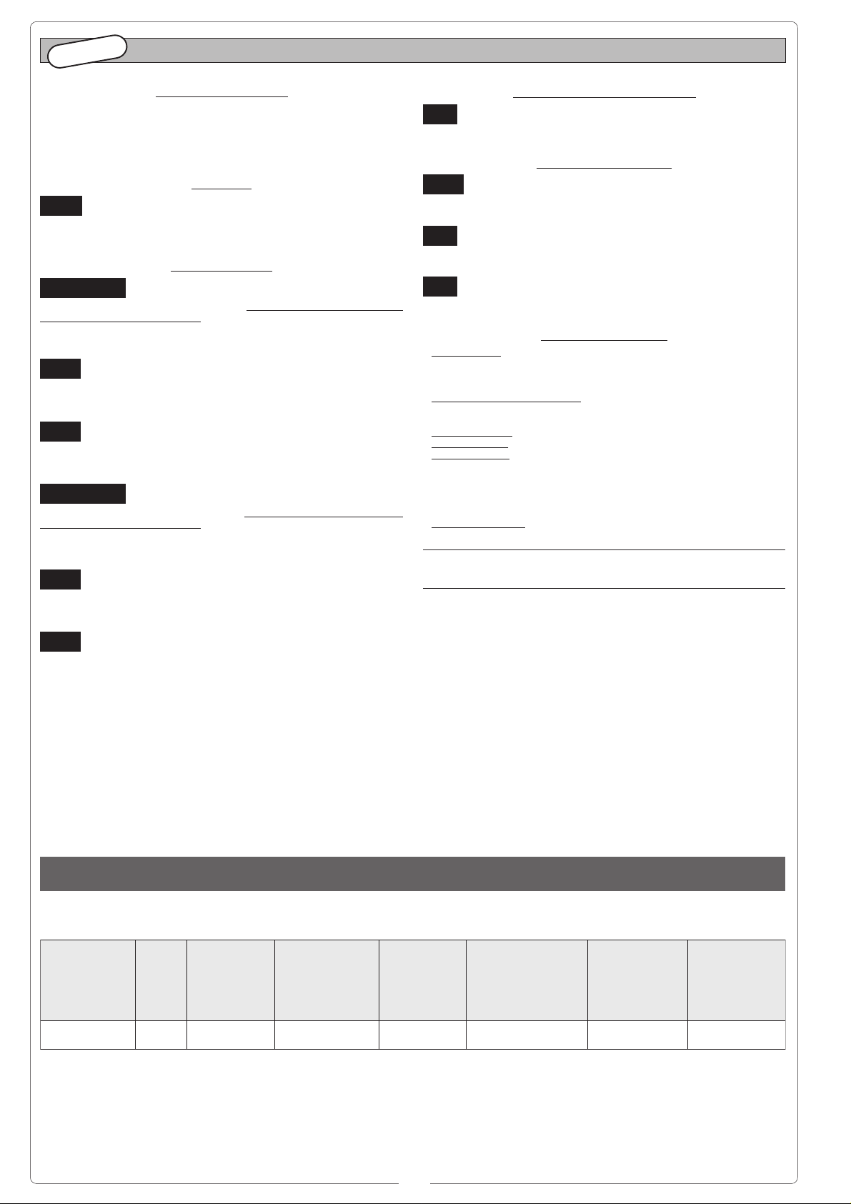
PORTA BASCULANTE A CONTRAPPESI, tipo a corsa verticale
debordante e a parziale rientranza
COUNTERWEIGHTED OVERHEAD DOOR, vertical stroke outward and
partially inward entry type
PORTE BASCULANTE Á CONTREPOIDS, type à course verticale
débordante et à retrait
GEGENGEWICHT-KIPPTOREN, Heraustragende-Vertikalbewegung
und
partial Ausparung Typ
PUERTA BASCULANTE POR CONTRAPESOS, tipo a recorrido
vertical desbordante y a entrada
PORTA BASCULANTE A MOLLE, tipo a corsa verticale
debordante e a
SPRING-BALANCED OVERHEAD DOOR, spring balanced, vertical
stroke outward and totally inward entry type
PORTE BASCULANTE Á RESSORTS, type à course verticale
débordante et à retrait
AUSGLEICHSFEDER-KIPPTOREN, HeraustragendeVertikalbewegung und
PUERTA BASCULANTE POR RESORTE, tipo a recorrido vertical
desbordante y a entrada
partielle
totale rientranza
totale
völlig Ausparung Typ
total
parcial
A
C
PORTA SEZIONALE
SECTIONAL DOOR
PORTE SECTIONNELLE
SEKTIONALTOR
PUERTA SECCIONAL
H
a singola guida
single sliding rail
à une seule guide
EinzelVerbindungsträger
a guía individual
A
BMESSUNGEN
18
140
400
MISURE D'INGOMBRO //
E
XTERNAL DIMENSIONS
Uscita cavi
Cable exit
Sortie cables
Netzkabeleingang
Salida de los cables
540 max*
H - 100mm
// MEASURES D'ENCOMBRENT //
* Per altezze superiori a tale valore, prevedere dei tiranti o staffe supplementari
For heights exceding 540 mm., it is necessary to use additional brackets or struts
Pour des hauteurs superieures a cette valeur, prevoir des tirants ou des etriers supplementaires
Bei Höhen, die obiges Maß überschreiten zusätzliche Schubstangen oder Bügel montieren
Para las alturas mayores que esta medida, se deben utilizar unos tirantes o soportes adicionales
DoppelVerbindungsträger
// DIMENSIONES
a doppia guida
double sliding rail
à double guide
a guía doble
212
PRESA E SPINA DI ALIMENTAZIONE //
STECK KONTAKTE FÜR BETRIEBSSPANNUNG
POWER SUPPLY PLUG AND OUTLET
// PRENSA Y ENCHUFE DE ALIMENTACIÓN
// PRISE ET FICHE D'ALIMENTATION //
USE ONLY 250V FUSES
NL
5
Page 6
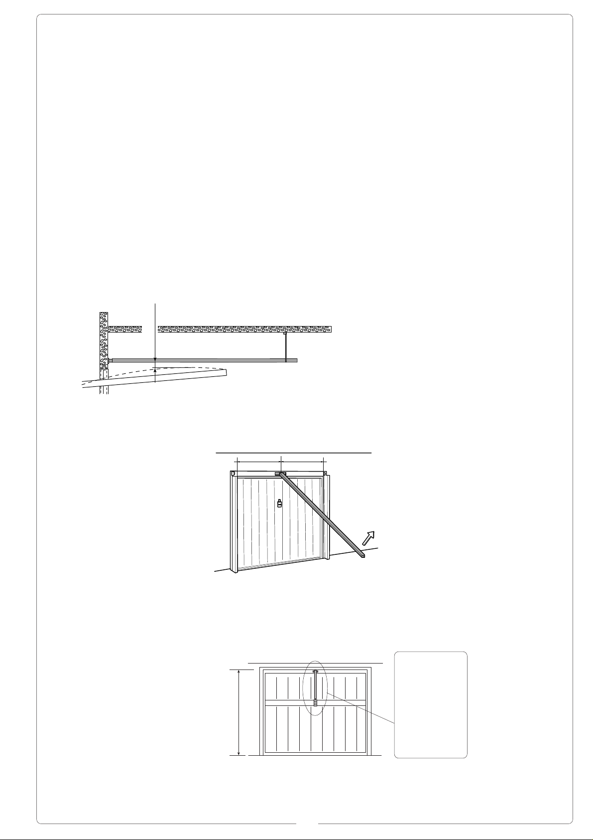
MONTAGGIO DEL GRUPPO //
Battuta superiore della porta
Upper edge of door
Point de fermeture supérieur de la porte
Obere T orkante
Punto de contacto superior de la puerta
30 ÷ 60 cm
=
=
Palo-molla
Spring-bar
Barre du ressort
Federbügel
Barra-resorte
UNIT ASSEMBLY
// MONTAGE DU GROUPE //
MONTAGE DER GRUPPE
// MONTAJE DEL GRUPO
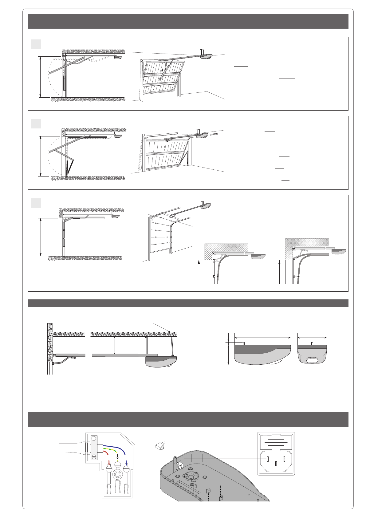
ITALIANO
PREDISPOSIZIONE
GUIDA DI TRASMISSIONE
- Fissare la staffa sul terminale anteriore della guida
di trasmissione con le viti in
dotazione;
FISSAGGIO GUIDA DI
TRASMISSIONE
ENGLISH
PREARRANGEMENT OF
TRANSMISSION RAIL
- Fasten the brac ket to the
transmission guide’s front
terminal with the screws
provided;
TRANSMISSION RAIL
FASTENING
FRANÇAIS
PRÉPARATION GUIDE
DE TRANSMISSION
- Fixer la bride sur l’élément
terminal avant du guide de
transmission avec les vis
fournies de série;
FIXATION GUIDE DE
TRANSMISSION
DEUTSCH
VORBEREITUNGS DER
ANTRIEBSGRUPPE
- Mit den zur Ausstattung
gehörenden Schrauben den
Bügel am vorderen Endstück der Antriebsgruppe
befestigen;
M6x20
M6
BEFESTIGUNG DER
ANTRIEBSGRUPPE
ESPAÑOL
PREDISPOSICIÓN GUÍA
DE TRANSMISIÓN
- Fijar la abrazadera en el
terminal anterior de la guía
de transmisión con los tornillos de serie;
FIJACIÓN GUÍA DE
TRANSMISIÓN
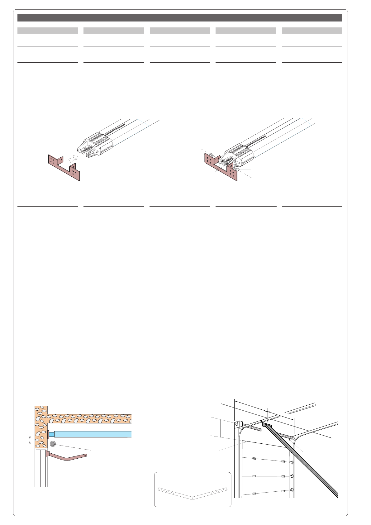
- Fissare la guida di trasmissione nel seguente
modo:
a) per porte sezionali
tipo C (vedi rif. pag. 5), fissare la staffa direttamente
sopra il palo-molla (figura
1), usando tasselli e viti
adeguati; se la distanza fra
il palo-molla e la battuta superiore del portone è compresa tra 30 e 60 cm,
applicare il braccio V122
(consultare la documentazione tecnica allegata all'accessorio);
- Fasten the transmission
rail in the following manner:
a) for sectional doors
C-type (see ref. p.5), fasten the bracket directly
over the spring-release
coiling shaft using adequate
dowels and screws; if the
distance between the coiling shaft and the gate’s upper ledge is between 30
and 60 cm, apply the V122
arm (read the technical
documentation provided
with the accessory);
- Fixer le guide de transmission de la façon suivante:
a) pour portes section-
nelle type C (voir réf. page
5), fixer la bride directement au-dessus de l’axe à
ressort, à l’aide de chevilles
et de vis appropriées; appliquer le bras V122 si la
distance entre l’axe à ressort et la butée supérieure
du portail est comprise entre 30 et 60 cm (consulter
la documentation technique
jointe à l’accessoire);
- Die Antriebsgruppe ist wie
folgt zu befestigen:
a) für Sektionaltoren
T yp C (siehe S. 5) den Bü-
gel direkt an der Wand
oberhalb der mit einer
Sprungfeder umwickelten
Welle befestigen. Dazu
sind angemessene Dübel
und Schrauben zu benutzen; falls der Abstand
zwischen der Welle und
dem oberen Toranschlag
zwischen 30 und 60 cm
liegt, ist der Arm V122
anzubringen.(die technische dem Zubehörteil anliegende technische Dokumentation zu Rate ziehen);
- Fijar la guía de transmisión de la siguiente manera:
a) para puertas seccio-
nal tipo C (véase ref. pág.
5), fijar la abrazadera directamente arriba de la barraresorte, usando tarugos y
tornillos adecuados; si la
distancia entre la barra-resorte y el punto de contacto superior de la puerta está
comprendida entre 30 y 60
cm, aplicar el brazo V122
(consultar la documentación técnica anexa al accesorio);
Fig./Abb. 1
20 á 30 mm
Palo-molla
Spring-bar
Barre du ressort
Federbügel
Barra-resorte
V122
6
Page 7
b) per porte basculanti tipo A-B (vedi rif. pag. 5),
verificare il punto massimo
di scorrimento dell'anta
(fig.2) e fissare di conseguenza in altezza la staffa
con viti o rivetti adeguati.
N.B.: per porte basculanti a
contrappesi debordanti, bisogna utilizzare il braccio
adattatore V201 (consultare la documentazione tecnica allegata all'accessorio).
Fig./Abb. 2
b) for A-B-type overhead
doors (see ref. p.5), veri-
fy the maximum door sliding point (fig.2) and consequently fasten the bracket
on high with adequate
screws or rivets.
N.B.: for counterweighted
overhead doors, partial entry, it is necessary to use
the adapter arm V201 (read
the technical documentation provided with the accessory).
b) pour portes bascu-
lantes type A-B (voir réf.
page 5), contrôler le point
maximum de coulissement
de la porte (fig.2) et fixer
proportionnellement la bride en hauteur avec des vis
ou des rivets appropriés.
N.B.: utiliser le bras d'adaptation V201 pour porte basculante á contrepoids, débordante, (consulter la documentation jointe à l’accessoire).
b) für Kipptoren Typ AB (siehe S. 5) den maxima-
len Gleitpunkt des Torflügels (Abb.2) feststellen und
aut der dementsprechenden Höhe den Bügel mit angemessenen Schrauben
oder Nieten befestigen.
Bitte beachten: Für Gegengewichtstor wird der Paßarm V201 benötigt (die die
Zubehörteil anliegende
technische Dokumentation
zu Rate ziehen).
b) para puertas bascu-
lantes tipo A-B (véase ref.
pág. 5), verificar el punto
máximo de deslizamiento
de la puerta (fig.2) y de consecuencia fijar la altura de
la abrazadera con tornillos
o remaches apropiados.
Nota: para puerta basculante a contrapeso de entrada
parcial, hay que utilizar el
brazo adaptador V201 (consultar la documentación
técnica anexa al accesorio).
10 ÷ 20 mm
==
H = 2.4 m max.
V201
7
Page 8
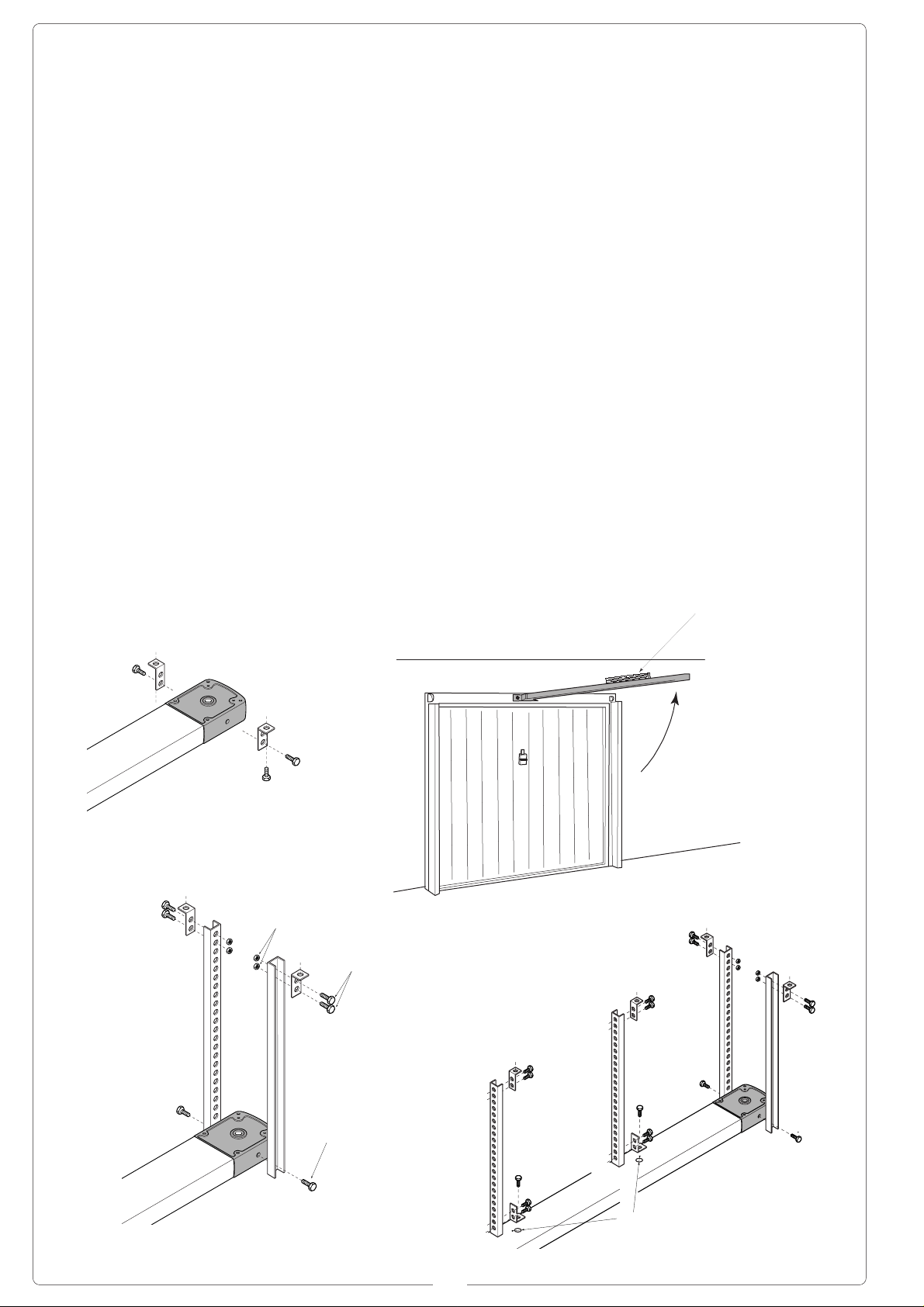
- Sollevare e disporre orizzontalmente la guida per rilevare la distanza dal soffitto; di conseguenza, fissare al terminale posteriore
della guida gli angolari oppure le staffe di fissaggio in
dotazione (tagliando l'eventuale eccedenza). N.B. nella guida di trasmissione
sono predisposti 3 fori ø7
per ulteriori fissaggi nel
caso si desideri rinforzare
il gruppo.
- Sollevare e fissare la guida di trasmissione al soffitto livellandola.
- Predisporre la traccia per
i collegamenti elettrici.
- Raise and set the guide
horizontally to establish the
distance from the ceiling;
then fasten the angle sections or fastening brackets
provided (cutting off any excess part) to the rail’s back
terminal. N.B. the transmission guide has three ø7
holes for further fastening
should it prove necessary
to reinforce the unit.
- Lift, level and fix the rail to
the ceiling.
- Prepare the chase for
electric wiring.
- Soulever et disposer le
guide horizontalement pour
relever la distance du plafond, fixer ensuite les cornières ou les brides de fixation fournies de série (en
coupant la partie en trop
éventuelle) à l’élément terminal arrière du guide.
N.B.: 3 trous ø7 sont prévus dans le guide de transmission pour fixer d’autres
éléments afin de renforcer
le groupe.
- Soulever , fixer et niv eler
la guide de transmission an
plafond.
- Prévoir la place pour les
branchements électriques;
Zur Feststellung des Dekkenabstands, die Antriebsschiene anheben und horizontal anbringen; am hinteren Endstück die Winkelprofile oder die zur Ausstattung gehörenden Befestigungsbügel (den überstehenden T eil ev entuell abschneiden) befestigen. N.B.
Zur eventuellen V erstärkung der Gruppe sind am
V erbindungsträger 3 Löcher
ø7 für weitere Befestigungen vorgesehen.
- Die Antriebsschiene anheben und rechtwinklig zur
Wand an der Decke befestigen.
- Den Elektrokabelkanal
vorbereiten.
- Levantar y colocar horizontalmente la guía para
detectar la distancia hasta
el techo; de consecuencia
fijar al terminal posterior de
la guía los angulares o las
abrazaderas de fijación de
serie (cortando la parte
eventualmente excedente).
Nota: en la guía de transmisión hay 3 agujeros ø7
para otras fijaciones en el
caso se desee reforzar el
grupo.
- Levante el riel, nivelelo y
fije al techo.
- Predisponer las huellas
para las conexiones eléctricas.
M6
Livella
Level
Niveau à bulle
im Wasser
Nivel
M6x14
M6x14
Ø7
8
Page 9
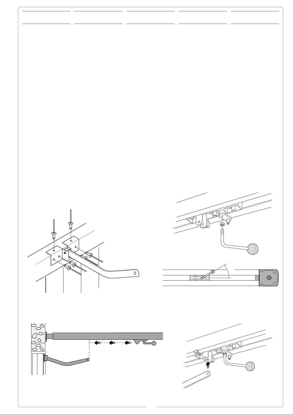
30˚
FISSAGGIO LEVE DI
TRAINO
SLIDING LEVER
FASTENING
FIXATION LEVIERS DE
TRACTION
BEFESTIGUNG DER
ZUGHEBEL
FIJACIÓN DE LAS
PALANCAS DE EMPUJE
- Fissare centralmente il
braccio di trasmissione al
traverso superiore della
porta con i rivetti in dotazione (o eventuali viti);
- Montare la manopola di
sblocco avvitandola sul
nottolino del gruppo sblocco premontato e fissarla
nella posizione consigliata
con il controdado;
- Spostare il pattino di scorrimento e agganciarlo al
braccio di trasmissione,
previo smontaggio della vite
premontata.
N.B.: nel caso di utilizzo del
braccio adattatore (V201)
agganciare il carrello al pattino di scorrimento.
- Centrally fix the transmission arm to the door’s upper crosspiece with the rivets provided (or possible
screws);
- Mount the unlocking handle by screwing it to the preassembled unlocking unit’s
revolving plug and fasten it
in the recommended position with the lock nut;
- Move the sliding runner
and hook it to the transmission arm after removing the
preset screw .
N.B.: if the adapter arm
(V201) is used, hook the
carriage to the sliding runner.
- Fixer le bras de transmission au centre de la traverse supérieure de la porte
avec les rivets fournis de
série (ou vis éventuelles);
- Monter la poignée de déblocage en la vissant sur le
mentonnet du groupe de
déblocage pré-monté et la
fixer dans la position conseillée avec le contreécrou;
- Déplacer le patin de coulissement et l’accrocher au
bras de transmission, après
avoir démonté la vis prémontée;
N.B.: accrocher le chariot
au patin de coulissement s’il
faut utiliser le bras adaptateur (V201).
- Am oberen Querträger
des T ores den Zughebel mit
den beiliegenden Nieten in
der Mitte befestigen (oder
eventuelle Schrauben);
- Den Entsperrgriff montieren und an den Sperrzahn
der vorher montierten Entsperrgruppe anschrauben
und anschließend mit der
Gegenmutter in der empfohlenen Stellung befestigen.
- Die Gleitbacke verschieben und nach vorherigem
Abbau der vormontierten
Schraube an den Antriebsarm einhaken.
N.B. Bei Gebrauch des Anpassungsarms (V201), den
Wagen an die Gleitbacke
haken.
- Fijar centralmente el brazo de transmisión en el travesaño superior de la puerta con los remaches de
serie (o posibles tornillos);
- Montar la manecilla de
desbloqueo enroscándola
en el pestillo del grupo de
desbloqueo premontado y
fijarla en la posición aconsejada con la contratuerca;
- Desplazar el patín de deslizamiento y engancharlo en
el brazo de transmisión,
desmontando previamente
el tornillo ya montado.
Nota: cuando se usa el brazo adaptador (V201) enganchar el carro al patín de
deslizamiento.
9
Page 10

INSTALLAZIONE DEL
MOTORIDUTTORE
GEARMOTOR
INSTALLATION
INSTALLATION DU
MOTORÉDUCTEUR
INSTALLATION DES
GETRIEBEMOTORS
INSTALACIÓN DEL
MOTORREDUCTOR
- Togliere il coperchio del
contenitore automazione,
agendo sulla vite ø3,9x13;
- Fissare il motoriduttore sul
terminale posteriore della
guida di traino nella posizione desiderata con le tre viti
ø6,3x45 in dotazione;
ø3,9x13
- Remove the automation
container cover
by unscrewing the ø3.9x13
screw;
- Fasten the gear motor to
the sliding rail’ s back terminal in the desired position
with the three ø6.3x45
screws provided;
- Enlever le couvercle du
boîtier de l’automatisme en
agissant sur la vis ø3,9x13;
- Fixer le motoréducteur sur
l’élément terminal arrière du
guide de traction dans la position désirée avec les trois
vis ø6,3x45 fournies de série.
- Durch Einwirken aut die
Schraube ø3.9x13 den
Deckel vom Kasten der
Automatik entfernen.
- Den Getriebemotors am
vorderen Endstück des
V erbindungsträgers mit den
drei beiliegenden Schrauben ø6.3 x45 an der gewünschten Stelle befestigen.
- Quitar la tapa del contenedor de automatización,
destornillando los tornillos
ø3,9x13;
- Fijar el motorreductor en
el terminal posterior de la
guía de empuje en la posición deseada con los tres
tornillos de serie ø6,3x45;
CAME
SBLOCCO DEL
MOTORIDUTTORE
- Agire sulla manopola
ruotandola come illustrato;
il riaggancio dello sblocco
avverrà automaticamente
alla prima manovra, riportando la manopola nella posizione iniziale.
- Se presente il dispositivo
di sblocco a cordino V121
(per il montaggio consultare la documentazione tecnica allegata all'accessorio), per bloccare e sbloccare il motoriduttore ruotare la maniglia come illustrato.
GEARMOTOR
UNLOCKING
- Turn the handle as illustrated; the rehooking of the
release will take place automatically at the first manoeuvre, re-setting the
handle in the original position.
- If there is a V121 cab le
release device (read the
technical documentation
accompanying the accessory for assembly instructions), turn the handle as
illustrated to lock and the
gearmotor.
ø6,3x45
DÉBLOCAGE DU
MOTORÉDUCTEUR
- Agir sur la poignée en la
tournant comme indiqué sur
la figure; le dispositif de déblocage se raccrochera
automatiquement à la première manœuvre en remettant la poignée dans sa position première.
- T ourner la poignée comme
indiqué sur la figure pour
bloquer et débloquer le motoréducteur si le dispositif
de déblocage à cordon
V121 est prévu (consulter
la documentation technique
jointe à l’accessoire pour le
montage).
ENTSPERRUNG DES
GETRIEBEMOTORS
- Den Griff wie dargestellt
drehen; die Entsperrung
klinkt bei der ersten Betätigung erneut ein und bringt
den Griff in Ausgangsstellung zurück.
- Bei einer Entsperrvorrichtung mit Schnur V121 (für
die Montage die dem Zubehörteil anliegende technische Dokumentation zu
Rate ziehen), ist zur Sperrung und Entsperrung des
Getriebemotors der Griff
wie dargestellt zu drehen
DESBLOQUEO DEL
MOTORREDUCTOR
- Girar la manecilla como
se muestra en la ilustración;
el reenganche del desbloqueo se efectuará automáticamente en la primera
maniobra, volviendo a poner la manecilla en la posición inicial.
- Si el presente dispositivo
de desbloqueo con cable
V121 (para el montaje consultar la documenticón técnica anexa al accesorio),
para bloquear y desbloquear el motorreductor girar la manilla como se
muestra en la ilustración.
10
V121
Page 11

DESCRIZIONE TECNICA SCHEDA COMANDO ZL55E
ITALIANO
La scheda va alimentata mediante presa di alimentazione con
tensione di 230V (a.c.) ed è protetta in ingresso con fusibile di
linea da 1.6A. I dispositivi di comando sono a bassa tensione e
protetti con fusibile da 315mA. La potenza complessiva degli
accessori a 24V, protetti da fusibile a 3.15A, non deve superare
i 40W.
Tempo di lavoro fisso 80 secondi.
Sicurezza
Le fotocellule possono essere collegate e predisposte per:
Riapertura
ostacolo durante la fase di chiusura della porta, provocano
l'inversione di marcia fino alla completa apertura;
-
Stop totale
del ciclo di chiusura automatica; per riprendere il movimento
bisogna agire sulla pulsantiera o sul radiocomando;
-
Test funzionamento fotocellule
chiusura dell’anta, la centralina verifica l'efficienza delle fotocellule
(vedi pag. 18).
-
Dispositivo amperometrico
Altre funzioni
-
Chiusura automatica.
si autoalimenta a fine-tempo corsa in apertura. Il tempo prefissato regolabile, è comunque subordinato dall'intervento di eventuali accessori di sicurezza e si esclude dopo un intervento di
"stop" o in mancanza di energia elettrica;
-
Rilevazione ostacolo
dopo un comando di stop totale), impedisce qualsiasi movimento
se i dispositivi di sicurezza (es. fotocellule) rilevano un ostacolo;
-
Funzione a "uomo presente"
tenendo premuto il pulsante (esclude la funzione del
radiocomando);
-
Prelampeggio.
lampeggiatore collegato su 10-E, lampeggia per 5 secondi prima
di iniziare la manovra;
in fase di chiusura (2-C1), le fotocellule rilevando un
(1-2), arresto della porta basculante con l'esclusione
. Ad ogni comando di apertura e
: vedi NOTA, pag 13.
Il temporizzatore di chiusura automatica
. A motore fermo (porta chiusa, aperta o
. Funzionamento della porta man-
Dopo un comando di apertura o di chiusura, il
Tipo di comando
-
- «apre-stop-chiude-stop» per pulsante e/o trasmettitore;
- «apre-chiude-inversione» per pulsante e/o trasmettitore;
- «solo apre» per pulsante e/o trasmettitore.
Accessori collegati
Lampada di cortesia
di manovra, dopo un comando di apertura, rimane accesa per un
tempo fisso di 2 minuti e 30 secondi.
Accessori opzionali
-
Lampada di cortesia
-
Lampeggiatore
10-E;
-
Lampada
-
Elettroblocco
-
Scheda V0670 per alimentazione mediante batterie
caso di mancanza di energia elettrica, interviene automaticamente. Al ripristino della tensione di linea, provvede alla ricarica
delle batterie stesse;
-
Scheda radiofrequenza AF
a distanza.
Regolazioni
- Trimmer TCA = Regolazione tempo chiusura automatica;
- Trimmer SENS = Regolazione della sensibilità amperometrica.
:
(24V-25W). Lampada che illumina la zona
(24V-25W), collegata ai morsetti 10-E3.
di movimento (25W max.), collegato ai morsetti
di segnalazione "porta aperta", collegata su 10-5;
(24V-15W max.), collegato su 10-S;
che, in
(vedi tabella pag. 24) per comando
Importante: dopo aver dato tensione all'impianto, la 1a manovra
è sempre in apertura. Durante questa fase non è possibile
chiudere la porta, è possibile richiuderla dopo la completa
manovra di apertura.
Attenzione! Prima di intervenire all’interno dell’appa-
recchiatura, togliere la tensione di linea e scollegare le
batterie (se inserite).
TECHNICAL DESCRIPTION ZL55E CONTROL PANEL
The card is powered with a 230V (AC) power outlet and its input
is protected with a 1.6A line fuse. Control systems are powered
by low voltage and protected by a 315mA fuse. The total power
consumption of 24V accessories (which are protected by a 3.15A
fuse) must not exceed 40W.
Fixed operating time of 80 sec.
Safety
Photocells can be connected to obtain:
-
Re-opening
detecting an obstacle while closing the door, cause the movement
direction to be reversed until opening is complete;
-
Total stop
of the automatic closing cycle. To resume the movement, use the
pushbutton or the radio control;
-
Photocell function test
safety system every time an opening or closing command is
given (see pag. 18).
-
Amperometric safety device
Other functions
-
Automatic closing.
activated at the end of the opening cycle. The preset, adjustable
automatic closing time is automatically interrupted by the activation
of any safety system, and is deactivated after a STOP command
or in case of power failure;
-
Obstacle detection
open or half-open after an emergency stop command), the
transmitter and the control pushbutton will be deactivated if an
obstacle is detected by one of the safety devices (for example,
the photocells);
-
"Operator present" function
pushbutton is held down (the radio remote control system is
deactivated);
-
Pre-flashing.
connected to the 10-E flashes for 5 seconds before beginning the
procedure;
during the closing cycle (2-C1), the photocells on
(1-2), stop of the garage-type door with the exclusion
. The control unit will now check the
: see NOTE, pag. 13
The automatic closing timer is automatically
. When the motor is stopped (gate is closed,
. Gate operates only when the
After an opening or closing command, the flascher
ENGLISH
Type of command
-
- «open-stop-close-stop» for pushbutton and radio transmitter;
- «open-close» for pushbutton and radio transmitter;
- «open only» for pushbutton and radio transmitter.
Accessories connected
-
Courtesy Light
manoeuvring zone; after an opening command, the light remains
on for a fixed time of 2 minutes and 30 seconds.
Optional accessories
-
Courtesy Light
-
Flashing signal light
connect it to terminal blocks 10-E;
- "Door open"
-
Electric lock
-
V0670 board card for emergency battery.
connected in case of power failure; battery is recharged when
line power is restored;
-
AF radiofrequency board
control.
Adjustments
- Trimmer TCA = adjustment automatic closing time;
- Trimmer SENS = adjustment sensitivity of amperometric safety
system.
:
(24V-25W). A light that illuminates the
(24V-25W), connect it to terminal blocks W-E;
when gate is in motion (24V-25W max.),
signal light
(24V-15W max.), connect it to 10-S;
, connect it to terminal blocks 10-5;
which is automatically
(see table on pg. 24) for remote
Important: after powering up the system, the 1st movement is
always the opening manoeuvre. During this stage it is not possible
to close the door. It is possible to re-close it after the door
completes the opening manoeuvre.
Caution! Shut off the mains power and disconnect the
batteries before servicing the inside of the unit.
11
Page 12

DESCRIPTION TECHNIQUE CARTE DE COMMANDE ZL55E
FRANÇAIS
La carte doit être alimentée à l'aide d'une prise d'alimentation
avec une tension de 230V (a.c.). Elle est protégée à l'entrée par
un fusible de 1.6A. Les dispositifs de commande sont à basse
tension et protégés avec un fusible de 315mA. La puissance
totale des accessoires en 24V, protégés par un fusible de 3,15A,
ne doit pas dépasser 40W.
Temps de fonctionnement fixe de 80 secondes.
Sécurité
Il est possible de brancher des photocellules et de les programmer
pour:
-
Réouverture
obstacle durant la phase fermeture des vantaux, les photocellules
provoquent l'inversion de marche jusq'à la ouverture compléte;
-
Stop total
cycle de fermeture automatique; pour activer de nouveau le
mouvement, il faut agir sur les boutons-poussoirs ou sur la
radiocommande;
-
Test fonctionnement photocellules
vérifier le bon fonctionnement des despositifs de securité aprés
chaque commande d'ouverture ou de fermeture (voir pag. 18).
-
Dispositif ampèremétrique
Autres fonctions
-
Fermeture automatique.
automatique est autoalimenté à la fin du temps de la course en
ouverture. Le temps réglable est programmé, cependant, il est
subordonné à l’intervention d’éventuels accessoires de sécurité
et il est exclu après une intervention de “stop” ou en cas de
coupure de courant;
-
Détection d'obstacle
ouvert ou semi-ouvert, cette position est obtenue avec une
commande de stop total), annule toute fonction de l’émetteur ou
du bouton-poussoir en cas d’obstacle détecté par les dispositifs
de sécurité (ex. Photocellules) ;
-
Fonction "homme mort"
maintenant appuyé le bouton-poussoir (exclut la fonction de la
radiocommande);
-
Pré-clignotement.
fermeture, le clignotant branché sur 10-E, clignote pendant 5
en phase de fermeture (2-C1), en détectant un
(1-2), arrêt du portail et désactivation d'un éventuel
. Cela permet au boítier de
: voir REMARQUE, pag. 13
Le temporisateur de fermeture
. Quand le moteur est arrêté (portail fermé,
. Fonctionnement du portail en
Après une commande d’ouverture ou de
TECHNISCHE BESCHREIBUNG GRUNDPLATINE ZL55E
secondes avant de commencer la manoeuvre;
-
Type de commande
- «ouverte-stop-fermée-stop» pour bouton-poussoir et/ou
émetteur radio;
- «ouverte-fermée» pour bouton-poussoir et/ou émetteur radio;
- «seulement ouverte» pour bouton-poussoir et/ou émetteur
radio.
Accessoires branchés
-
Lampe passagge
manoeuvre, après une commande d'ouverture elle reste allumée
pour une durée fixe 2 minutes et 30 secondes.
Accessoires en option
-
Lampe passegge
-
Clignotant de mouvement
10-E;
-
Lampe
10-5;
-
automatiquement en cas d'absence d'énergie électrique, au
rétablissement de la tension de ligne, la carte procède au
rechargement de la batterie;
commande à distance.
Réglages
- Trimmer TCA = Réglage temps de fermeture automatique;
- Trimmer SENS = Réglage sensibilité ampèremétrique.
de signalisation "portail ouvert", brancher aux bornes
Serrure électrique
Carte V0670 pour l'alimentation par batterie
Carte radiofréquence à AF
Important: la 1
:
(24V-25W). Lampe qui illumine la zone de
(24V-25W), la brancher aux bornes 10-E3;
ère
manœuvre est toujours en ouverture après
(24V-25W max.), brancher aux bornes
(24V-15W max), brancher aux bornes 10-S;
intervenant
(voir tableau page 24) pour la
avoir donné du courant à l’installation. Il est impossible de
refermer la porte durant cette phase car il faut attendre que la
manœuvre d’ouverture soit terminée.
Attention! Avant d'intervenir à l'intérieur de
l'appareillage, couper la tension de ligne et débrancher les
batteries (si branchées).
DEUTSCH
Die Karte wird durch eine Speisesteckdose mit Spannung von
230 (Wechselstrom) gespeist und ist in Eingang durch eine
Leitungssicherung von 1.6A geschützt. Die Steuerungen erfolgen
mit Niederspannung und geschützen enie 315mA-Sicherung.
Die Gesamtleistung des durch eine 3.15-A-Sicherung geschützten
24-V-Zubehörs darf 40W nicht überschreiten.
Festgelegte Laufzeit von 80 Sek.
Sicherheitsvorrichtungen
Die Lichtschranken können für folgende Funktionen
angeschlossen bzw. vorbereitet werden:
-
Wiederöffnen
erfassen beim Schließen der Torflügel ein Hindernis und lösen
die Umkehrung der Laufrichtung bis zum vollständigen Öffnen
aus;
-
Totalstop
eventueller Schließautomatik: Fortsetzung des Torlaufs über
Drucktaster- bzw. Funksendersteuerung;
-
Test für das funktionieren der lichtschranken
die Möglichkeit, die Leistungsfáhigkeit der Sicherheitsvorrichtungen nach jeder Öffnungs-und Schließsteuerung zu
überprüfen (siehe Seite 19).
-
Amperemetrische Vorrichtung
Andere Funktionen
-
Schließautomatik.
beim Öffnen am Ende der Torlaufzeit selbst. Die voreingestellte
Zeit ist auf jeden Fall immer dem Eingriff eventueller Sicherheitsvorrichtungen untergeordnet und schließt sich nach einem
“Stop”-Eingriff bzw. bei Stromausfall selbst aus;
-
Hinderniserfassung
geöffnet oder durch eine Totalstop-Steuerung halb geöffnet)
wird bei durch die Sicherheitsvorrichtungen (z.B.: Lichtschranken)
erfaßtem Hindernis jede Sender- oder Drucktasterfunktion
annulliert;
-
Funktion "Bedienung vom Steuerpult"
tasterbetätigung (Funkfernsteuerung ausgeschlossen);
-
Vorblinken.
gegeben worden ist, blinkt das Blinklicht, das an 10-E
angeschlossen ist, zunächst 5 Sekunden, bevor das Manöver
beim Schließen (2-C1), die Lichtschranken
(1-2), sofortiger Stillstand des Tores mit Ausschluß
. Dadurch besteht
: siehe HINWEIS, Seite 13
Der Schließautomatik-Zeischalter speist sich
. Bei stillstehendem Motor (Tor geschlossen,
. Torbetrieb durch Druck-
Nachdem der Befehl zum Öffnen oder Schließen
beginnt;
Steuerart
-
- «Öffnen-stop-Schließen-stop» für Drucktaster- und
Funksendersteuerart;
- «Öffnen-Schließen» für Drucktaster- und Funksendersteuerart;
- «nur Öffnen» für Drucktaster- und Funksendersteuerart.
Angeschlossenes Zubehör
-
Torbeleuchtung
des Tors gegeben worden ist, bleibt das Licht, das den
Manöverbereich am Tor beleuchtet, für eine vorgegebene Zeit
von 3 Minuten und 30 Sekunden eingeschaltet.
Extrazubehör
-
Torbeleuchtung
-
Blinkleuchte
-
Anzeigeleuchte für "Tor öffen
-
Elektrische Verriegelung
10-S;
-
Steckplatine V0670 für Stromversorgung über Notbatterie,
sich bei Stromausfall automatisch zuschaltet und die Batterie bei
erneuter Netz-Stromversorgung wieder auflädt;
-
Funkfrequenzkarte AF
Fernsteuerung.
Einstellungen
- Trimmer TCA = Zeiteinstellung Schließautomatik;
- Trimmer SENS = Einstellung der amperemetrischen.
Wichtig:
1° Betätigung immer beim Öffnen. Während dieser Phase kann
das Tor nicht geschlossen werden. Es kann ausschließlich nach
einem kompletten Öffnungsvorgang erneut geschlossen werden.
:
(24V-25W). Nachdem der Befehl zum Öffnen
(24V-25W), mit den Klemmen 10-E3;
(24V-25W max.), mit den Klemmen 10-E;
", mit den Klemmen 10-5;
(24V-15W max.), mit den Klemmen
(siehe Tabelle Seite 24) für
Nach Versorgung der Anlage mit Spannung, erfolgt die
Achtung! Das Gerät vor Eingriffen im inneren
spannungsfrei schalter und die Stromzufuhr mittels
Batterien (falls zugeschaltet) unterbrechen.
12
die
Page 13

DESCRIPCIÓN TÉCNICA TARJETA DE MANDO ZL55E
ESPAÑOL
La tarjeta se debe alimentar mediante toma de alimentación con
tensión de 230V (c.a.) y está protegida a la entrada con fusible
de línea de 1.6A. Los dispositivos de mando son a baja tensión
y està protegidos por fusible a 315mA. La potencia total de los
accesorios a 24V, protegidos por fusible a 3.15A, no debe
superar los 40W.
Tiempo de trabajo fijo a 80 seg.
Seguridad
Las fotocélulas pueden estar conectadas y predispuestas para:
Reapertura
un obstáculo durante la cierre de la hojas, causando la inversión
del movimiento hasta que se abre totalmente;
-
Parada total
ciclo de cierre automático; para reactivar el movimiento es
preciso actuar en el teclado o en el mando a distancia;
-
Test funcionamiento fotocelulas
la eficiencia en los dispositivos de seguridad después de cada
comando de apertura y cierre (véase pág. 19).
-
Dispositivo amperométrico
Otras funciones
-
Cierre automático.
autoalimenta en fin-de-tiempo carrera en fase de apertura. El
tiempo prefijado regulable, sin embargo, está subordinado a la
intervención de posibles accesorios de seguridad y se excluye
después de una intervención de parada o en caso de falta de
energía eléctrica;
-
Detección obstáculo
abierta o en posición semi-abierta obtenida a través de un
comando de stop total), anula cualquier función del transmisor o
del botón en caso de obstáculo detectado por los dispositivos de
seguridad (por ejemplo: fotocélulas);
-
Función a "hombre presente"
manteniendo pulsada la tecla (excluye la función del mando a
distancia);
-
Preintermitencia.
la lámpara intermitente conectada en 10-E, parpadea por 5
segundos antes de comenzar la manibra;
en la fase de cierre (2-C1), las fotocélulas detectan
(1-2), parada de la puerta excluyendo el posible
. Permite a la central comprobar
: mirar NOTA, pag. 13
El temporizador de cierre automático se
. Con el motor parado (puerta cerrada,
. Funcionamiento de la puerta
Después de un mando de apertura o cierre,
NOTA // NOTE // REMARQUE // HINWEIS // NOTA
Tipo di mando
-
- «apertura-parada-cierre-parada» para tecla y/o trasmisor de
radio;
- «apertura-parada» para tecla y/o trasmisor de radio;
- «sólo apertura» para tecla y/o trasmisor de radio;
Accesorios conectados
Lámpara de cortesía
de maniobra; tras un mando de apertura permanece encendida
por 2 minutos y 30 segundos.
Accesorios opcionales
-
Lámpara de cortesía
-
Lámpara intermitente de movimiento
a los bornes 10-E;
-
Lámpara de señal
10-5;
-
Electrocerradura
S;
-
Tarjeta V0670 para la alimentación mediante batería,
caso de falta de energía eléctrica, interviene automáticamente;
una vez conectada de nuevo la tensión de línea, se ocupa de
cargar la batería misma;
-
Tarjeta de radiofrecuencia AF
mando a distancia.
Regulación
- Trimmer TCA = Regulación tiempo cierre automático;
- Trimmer SENS = Regulación sensibilidad amperimétrica.
:
(24V-25W). Lámpara que ilumina la zona
(24V-25W), conéctela a los bornes 10-E3;
(24V-25W max.), conéctela
de "puerta abierta", conéctela a los bornes
(24V-15W max.), conéctela a los bornes 10-
que en
(véase tabla pág. 24) para el
Importante: después de haber dado tensión al equipo, la primera
maniobra es siempre de apertura. Durante esta f ase no se puede
cerrar la puerta, es posible cerrarla después de una maniobra
completa de apertura.
¡Atención! Antes de actuar dentro del aparado, quitar
la tensión de línea y desecnectar las baterías (si estuvieran
conectadas).
ITALIANO
Il dispositivo amperometrico, in presenza di
ostacolo, provoca:
a) l'arresto dell'anta durante la fase di apertura
con successiva chiusura automatica (se attivata);
a)
b) l'inversione di marcia
se in fase di chiusura.
Attenzione: nel caso b,
dopo 3 rilevamenti
d'ostacolo consecutivi,
l'anta si ferma in apertura e viene esclusa la chiusura automatica; per riprendere il movimento
bisogna agire sulla pulsantiera o sul radiocomando.
ENGLISH
In the presence of an
obstacle, the amperometric device:
a) completely stops the
door during opening
and subsequently closes it automatically (if activated);
b) if in the closure phase,
the movement of the door
is reversed.
N.B.: In situation (b), if an
obstacle is detected three
times, the door wing stops
during aperture, and automatic closure is
disactivated.
Use the keyboard or the
radio transmitter to
resume movement of the
bar.
FRANÇAIS
En présence d’un obstacle, le dispositif ampèremétrique provoque:
a) l’arrêt de la porte durant la phase d’ouverture suivi de la fermeture
automatique (si elle est
activée);
b) si en phase de fermeture, l'inversion du mouvement.
Attention
b), après 3détections
d'obstacle consécutives,
la vantail s'arrête en
ouverture et la fermeture
automatique est exclue.
Pour reprendre le mouvement, il faut agir sur les
boutons-poussoirs ou
sur la radiocommande,
: dans le case
DEUTSCH
Die Stromvorrichtung
löst bei Vor liegen eines
Hindernisses folgendes
aus:
a) Anhalten des Torflügels während des Öffnens mit anschließendem automatischen
Schließen (falls aktiviert).
b) in der Schließphase
die Bewegungsumkehr
(Sicherheitsrücklauf).
Achtung: Im Fall b) bleibt
der Flügel nach 3 hintereinandererfolgten
Hinderniserfassungen
offen und die Schließautomatik wird ausgeschaltet.
Die Wideraufnahme des
Normalbetriebes erfolgt
mittels Tasten- bzw.
Funksteuerung.
ESPAÑOL
El dispositivo amperométrico, en presencia de
obstáculos, provoca:
a) la parada de la puerta durante la apertura
con el sucesivo cierre
automático (si está activado);
b) en fase de cierre la
inversión de la marcha.
¡Atención!: En el caso
b), despus de 3 detecciones de obstaculo consecutivas, la puerta se
para en apertura y se
excluye el cierre automatico; para reactivar el
movimiento se debe actuar en el teclado o en el
mando a distancia.
b)
13
Page 14

QUADRO COMANDO //
1
C
ONTROL PANEL
// ARMOIRE DE COMMANDE //
S
CHALTTAFEL
GRÜN/GELB - VERDE/AMARILLO
// CUADRO DE MANDO
3
2
VERDE - GREEN - VERT - GRÜN - VERDE
6
ROSSO - RED - ROUGE - ROT - ROJO
34V26V17V 0V
7
4
FUS. MOTORE 8A
MN+E -
8
1516
MARRONE - BROWN - MARRON - BRAUN - CASTÀÑO
VERDE/GIALLO - GREEN/YELLOW - VERT/JAUNE
VERDE - GREEN - VERT - GRÜN - VERDE
BIANCO - WHITE - BLANC - WEIß - BLANCO
MARRONE - BROWN - MARRON - BRAUN - CASTAÑO
AZZURRO - BLUE - BLEU - BLAU - AZUL
ROSSO - RED - ROUGE - ROT - ROJO
BIANCO - WHITE - BLANC - WEIß - BLANCO
CH1
APRE
9 10
T.C.A.
CHIUDE
11
0V
230V
5
SENS.
AP / CH
12 13
0
17
26
2
1 345678910
ON
14
ZL55E
FUS.
ACC. 3,15A
17
FUS. CENTR. 315mA
14
18
AF
19
Page 15

QUADRO COMANDO //
C
ONTROL PANEL
// ARMOIRE DE COMMANDE //
S
CHALTTAFEL
// CUADRO DE MANDO
Principali componenti
1 - Spina di alimentazione 230V
2 - Fusibile di linea 1,6A
3 - Locazione per batterie di emergenza
4 - Motoriduttore
5 - Trasformatore
6 - Morsettiera collegamento trasformatore
7 - Fusibile motore 8A
8 - Morsettiera collegamento motoriduttore ed encoder
9 - Led segnalazione
10 - Pulsanti di memorizzazione codice radio e programmazio-
ne dei finecorsa
11 - Trimmer regolazione tempo chiusura automatica
12 - Trimmer regolazione della sensibilità amperometrica
13 - Pulsante di memorizzazione encoder + apertura e
chiusura della porta
14 - Selettore funzioni a 10 dip (pag. 20)
15 - Lampada di cortesia
16 - Fusibile accessori 3,15A
17 - Fusibile centralina 315mA
18 - Morsettiera di collegamento accessori e comandi
19 - Innesto scheda radiofrequenza "AF"
Principaux composants
1 - Fiche d'alimentation 230V
2 - Fusible de ligne 1,6A
3 - Logement pour les batteries d'urgence
4 - Motoreducteur
5 - Transformateur
6 - Plaque à bornes de branchement transformateur
7 - Fusible moteur 8A
8 - Plaque à bornes de branchement motoréducteur et
encoder
9 - Led de signalisation
10 - Boutons de mémorisation code radio et programmation
des interrupteurs de fin de course
11 - Trimmer TCA: réglage temps de fermeture auomatique
12 - Trimmer SENS: réglage sensibilité ampèremétrique
13 - Bouton de mémorisation encoder + ouverture et fermeture
de la porte
14 - Selecteur de fonctions à 10 interrupteurs (pag. 20)
15 - Lampe passagge
16 - Fusible accessoires 3,15A
17 - Fusible boîtier 315mA
18 - Plaque à bornes de branchement des accessoires et des
commandes
19 - Branchement carte radiofréquence "AF"
ITALIANO
FRANÇAIS
Principales Componentes
1 - Enchufe de alimentación 230V
2 - Fusible de línea 1,6A
3 - Ubicación para baterías de emergencia
4 - Motorreductor
5 - Transformador
6 - Placa de bornes para conexión del transformador
7 - Fusible motor 8A
8 - Placa de bornes para conexión del motorreductor y encoder
9 - Led de señal
10 - Pulsadores de memorización del código radio y programación de
los finales de carrera
11 - Trimmer TCA: regulación tiempo ciere automático
12 - Trimmer SENS: regulación sensibilidad amperimétrica
13 - Botón de memorización encoder + apertura y cierre de la puerta
14 - Selector de fonciones con 10 dip (pag. 20)
15 - Lámpara de cortesía
16 - Fusible accesorios 3,15A
17 - Fusible para central 315mA
18 - Placa de bornes de conexión accesorios y mandos
19 - Conexión tarjeta radiofrecuencia "AF"
Main compoments
1 - 230V electric plug
2 - Line fuse, 1,6A
3 - Location for emergency batteries
4 - Gearmotor
5 - Transformer
6 - Transformer connection terminal board
7 - Motor fuse, 8A
8 - Gearmotor and encoder connection terminal board
9 - Signal LED
10 - Radio code and limit switch programming memorisation
buttons
11 - Trimmer TCA: automatic closing time adjustment
12 - Trimmer SENS: amperometric sensitivity adjustment
13 - Encoder memorisation button + gate opening and closing
14 - 10-dip function switch (pag. 20)
15 - Courtesy Light
16 - Accessoires fuse, 3,15A
17 - Central control unit fuse, 315mA
18 - Accessory and control connection terminal board
19 - "AF" radiofrequency board socket
Hauptkomponenten
1 - Speisestecker 230V
2 - 1,6A-Sicherung Leitungs
3 - Raum für Notbatterien
4 - Getribemotor
5 - Transformator
6 - Anschlußklemmenbrett Transformator
7 - 8A-Sicherung Motor
8 - Anschlußklemmenbrett Getriebemotor und Encoder
9 - LED Kontrolleuchte zur Anzeige
10 - Speichertasten Funkcodes und
Endschalterprogrammierung
11 - Trimmer TCA: Einstellung der Schließautomatik
12 - Trimmer SENS: Einstellung der amperemetrischen
13 - Drucktaste zur Speicherung von Encoder + Türöffnungs-
und Türschließung
14 - Wählschalter für Funktionen mit 10 Dip (pag. 20)
15 - Torbeleuchtung
16 - 3,15A-Sicherung Zubehör
17 - 315mA-Sicherung Schaltkasten
18 - Anschlußklemmenbrett Zubehörteile und Steuerungen
19 - Einschalten Funkfrequenzkarte "AF"
ESPAÑOL
15
ENGLISH
DEUTSCH
Page 16

COLLEGAMENTI ELETTRICI //
E
LEKTRISCHE ANSCHLÜSSE
E
LECTRICAL CONNECTIONS
// CONEXIONES ELÉCTRICAS
// BRANCHEMENTS ÉLECTRIQUES //
10 11 E E3 TS S 1 2 3 5 7 C1
M
N
MN+E-
Motore 24V (d.c.)
24 (d.c.) motor
Moteur 24V (d.c.)
Motor 24V (Gleichstrom)
Motor 24V (d.c.)
Alimentazioni accessori (max 40W)
- 24V (A.C.) con alimentazione a 230V (A.C.)
- 24V (D.C.) con alimentazione a 24V (D.C.)
Powering accessories (max 40W)
- 24V (A.C.) with power supply at 230V (A.C.)
- 24V (D.C.) with power supply at 24V (A.C.)
+
10
11
-
Alimentation accessoires (max 40W)
- 24V (a.c.) avec alimentation en 230V (a.c.)
- 24V (d.c.) avec alimentation en 24V (d.c.)
Zubehörspeisung (max 40W)
- 24V (Wechselstrom) bei Stromversorgung 230V (Wechselstrom)
- 24V (Gleichstrom) bei Stromversorgung 24V (Gleichstrom)
Alimentación accesorios (max 40W)
- 24V (a.c.) con alimentación 230V (a.c.)
- 24V (d.c.) con alimentación 24V (d.c.)
10
E
10
E3
10
S
Uscita 24V in movimento (es.lampeggiatore 25W)
24V output in motion (e.g. flashing light)
Sortie 24V en mouvement (ex. branchement clignotant)
Ausgang 24V in Bewegung (z.B. Blinker-Anschluß)
Salida de 24V en movimento (p.ej. conexión lámpara intermitente)
Lampada di cortesia 24V - 25W max.
24V - 25W max. courtesy light
Lampe de passagge 24V - 25W max.
Torbeleuchtung 24V - 25W max.
Lámpara de cortesía 24V - 25W max.
Collegamento elettroblocco 24V (a.c.) 15W max.
Connection for electric blocking system: 24V (a.c.) 15W max.
Connexion du bloc de fermeture électrique 24V (c.a.) 15W max.
Elektro-Schließsperre Anschluß 24V (Wechselstrom) 15W max.
Conexión electrobloqueo 24V (a.c.) 15W max.
16
Page 17

10
5
2
3
1
2
Lampada spia porta aperta 24V - 3W max.
24V - 3W max. door-open signal lamp
Lampe-témoin "portail ouvert" 24V - 3W max.
Kontrollampe "Tor geöffnet" 24V - 3W max.
Làmpara indicadora 24V - 3W max. "puerta abierta"
Pulsante stop (N.C.)
Pushbutton stop (N.C.)
Bouton-poussoir arrêt (N.F.)
Stop-Taste (Ruhekontakt)
Pulsador de stop (N.C.)
Pulsante di apertura (N.O.)
Pushbutton opens (N.O.)
Bouton-poussoir de ouverture (N.O.)
Taste (Arbeitskontakt) für Öffnung
Pulsador de apertura (N.O.)
2
C1
2
7
Contatto (N.C.) di «riapertura durante la chiusura»
Contact (N.C.) for «re-aperture during closure»
Contact (N.F.) de «réouverture pendant la fermeture»
Kontakt (Ruhekontakt) Wiederöffnen beim Schliessen
Contacto (N.C.) para la apertura en la fase de cierre
Pulsante per comandi (N.O.) vedi selezione sul dip n° 2 o pulsante di chiusura
nel funzionamento a "uomo presente" dip n° 6 in ON.
Pushbutton for commands (N.O.) see selection on dip switch No. 2 or closing
pushbutton in "operation present" operation, dip switch No. 6 in ON position.
Bouton pour les commandes (N.O.) voir sélection sur le microinterrupteur n°2
ou bouton de fermeture lors du fonctionement "homme mort",
microinterrupteur n°6 sur ON.
Drucktaste für Steuerungen (N.O.) siehe Wahl auf Dip N° 2 oder Veschlußdrucktaste
bei Betrieb "Bedienung vom Steuerpult" Dip N° 6 auf ON.
Pulsador para mandos (N.O.) véase selección en el dip n° 2 o pulsador de cierre
en el funcionamiento en modo "hombre presente" dip n° 6 en ON.
Collegamento antenna
Antenna connection
Connexion antenne
Antennenanschluß
Conexión antena
N.B. Tutti i contatti e
pulsanti normalmente
chiusi (N.C.) non usati
devono essere disinseriti
mediante dip-switch o
cortocircuitati.
N.B. All normally closed
(N.C.) contacts and buttons not used should be disconnected with a dipswitch
or short-circuited.
N.B. Tous les contacts et
les boutons normalement fermés (N.C.) qui ne
sont pas utilisés doivent
être déconnectés à l’aide
de l’interrupteur à bascule ou court-circuités.
17
N.B. Alle gewöhnlich geschlossenen (N.C.) nicht
benutzten Kontakte und
Drucktasten müssen durch
dip-switch ausgeschaltet
werden oder kurzgeschlossen sein.
Nota: todos los contactos y pulsadores normalmente cerrados (N.C.)
que no se usan deben
ser desconectados mediante dip-switch o cortocircuitados.
Page 18

TEST FUNZIONAMENTO FOTOCELLULE //
T
EST FÜR DAS FUNKTIONIEREN DER LICHTSCHRANKEN
P
HOTOCELL FUNCTION TEST
// TEST FONCTIONNEMENT PHOTOCELLULES //
// TEST FUNCIONAMIENTO FOTOCELULAS
ITALIANO
Consente alla centralina di verificare l'efficenza dei dispositivi
di sicurezza (fotocellule) dopo ogni comando di apertura o di
chiusura. Un eventuale anomalia delle fotocellule viene identificata con un lampeggio del led sul quadro comando, di
conseguenza annulla qualsiasi funzione del radiocomando e
del pulsante.
Collegamento elettrico per il funzionamento del test di sicurezza.
I trasmettitori e i ricevitori delle fotocellule della serie DOC
devono essere collegati nel seguente modo:
- il trasmettitore della fotocellula collegato sui morsetti TS-10,
mentre il ricevitore collegato sui morsetti 10-11 (vedi FIG.1).
Per le fotocellule della serie DIR, i collegamenti devono
essere eseguiti nel seguente modo:
- il morsetto 2 della fotocellula del trasmettitore collegato al
morsetto TS della scheda ZL55E;
- i morsetti 10-2 del ricevitore collegati ai morsetti 10-2 della
scheda ZL55E;
- le fotocellule devono essere collegate tra loro utilizzando i
morsetti TX (vedi FIG.2).
Selezionare il dip 9 in ON per attivare il funzionamento del
test.
FIG. 1
ABB. 1
«DOC»
FIG. 2
ABB. 2
+
-
C.
N.O.
N.C.
10 11 E E3 TS S 1 2 3 5 7 C1
FUSIBILE 200mA
+
C
10 2 TX
NC
TX 2
TX
2
+
-
ENGLISH
The control unit will now check the safety system (photocells)
every time an opening or closing command is given. If a
photocell malfunctions, a LED will flash on the control panel,
and the radio transmitter and the control pushbutton will be
deactivated.
Electrical connections required for safety test function.
Photocell series DOC, lamps and sensors must be connected
as follows:
- connect the photocell sensor across terminals TS-10. Connect
the photocell lamp across terminals 10-11 (see FIG.1).
For DIR series photocells, the connections should be made as
follows:
-terminal 2 of the photocell transmitter connected to terminal
TS of the ZL55E board;
-terminal 10-2 of the receiver connected to terminals 10-2 of
the ZL55E board;
-the photocells should be connected together using terminals
TX (see FIG.2)
- move dip switch 9 to ON, which will activate the test function.
«DIR»
+
-
10 11 E E3 TS S 1 2 3 5 7 C1
FRANÇAIS
-
Cela permet au boîtier de vérifier le bon fonctionnement des
dispositifs de sécurité (photocellules) aprés chaque commande
d'ouverture ou de fermeture. Les éventuelles anomalies des
photocellules sont signalées par un clignotement de la led sur
l'armoire de commande, et la conséquente annulation de
toute fonction de l'émetteur et du bouton-poussoir.
Branchement électrique pour le fonctionnement du test de
sécurité.
Les émetteurs et les récepteurs des photocellules série DOC
doivent être branchés de la manière suivante:
-l'émmetteur de la photocellule sur le bornes TS-10, celui du
récepteur sur les bornes 10-11 (voir FIG.1).
Pour les photocellules de la sèrie DIR, les branchements
doivent être effectués de la façon suivante:
-brancher la borne 2 de l'émetteur de la photocellules à la
borne TS de la carte ZL55E;
-brancher les bornes 10-2 du récepteur aux bornes 10-2 de la
carte ZL55E;
-brancher les photocellules entre elles en utilisant les bornes
TX (voir FIG.2).
Mettre le dip-switch 9 sur ON pour activer le fonctionnement
du test.
18
Page 19

DEUTSCH
ESPAÑOL
Dadurch besteht die Möglichkeit, die Leistungsfähigkeit der
Sicherheitsvorrichtungen (Lichtschranken) nach jeder
Öffnungs- und Schließsteuerung zu überprüfen.
Bei eventuell auftretenden Betriebsstörungen der
Lichtschranken leuchtet die entsprechende LED auf dem
Steuergerät auf und jede Funksender- und DrucktasterFunktion wird automatisch annulliert.
Elektrischer Anschluß für die Sicherheitstest-Funktion.
Die Sender und Empfänger der Lichtschranken DOC
folgendermaßen anschließen:
-Lichtschrankensender auf den Klemmen TS-10, Empf änger
auf den Klemmen 10-11 (siehe Abbildung 1).
Die Anschlüsse der Fotozellen der Baureihe DIR bitte
folgendermaßen durchführen:
-Schließen Sie die Klemme 2 des Senders der Fotozelle an
die Klemme TS der ZL55E karte an;
-Schließen Sie die Klemmen 10 und 2 des Empfängers an
die Klemmen 10 und 2 der ZL55E karte an;
-Die einzelnen Fotozellen müssen mithilfe der Klemmen TX
(siehe Abbildung 2) miteinander verbunden werden.
Dip-Switch 9 zur Aktivierung der Sicherheitstest-Funktion auf
ON stellen.
Permite a la central comprobar la eficiencia en los dispositivos
de seguridad (fotocélulas) después de cada comando de
apertura y cierre. Una posible anomalía de las fotocélulas se
indica a través de una luz parpadeante del LED en el cuadro
de mando y, por lo tanto, se anula cualquier función del
transmisor y de la tecla.
Conexión eléctrica para el funcionamiento de las pruebas de
seguridad.
Los transmisores y los receptores de las fotocélulas serie
DOC deben estar conectados de la siguiente manera:
-el transmisor de la fotocélula conectado a los bornes TS-10,
el receptor a los bornes 10-11 (ver FIG.1).
Para las fotocélulas de la serie DIR, las conexiones se tienen
que realizar de la forma siguiente:
-el borne 2 del transmisor de la fotocélulas se conecta al borne
TS de la tarjeta base;
-el bornes 10-2 del receptor se conectan a los bornes 10-2 de
la tarjeta base;
-las fotocélulas se han de conectar utilizando los bornes TX
(ver FIG.2).
Seleccionar el dip 9 en ON para activar el funcionamiento de
la prueba.
19
Page 20

SELEZIONI FUNZIONI //
S
ELECTION OF FUNCTIONS
ITALIANO
// SÉLECTION FONCTIONS //
F
UNKTIONSWAHL
// SELECCIÓN DE LAS FUNCIONES
1 ON Chiusura automatica attivata;
2 ON "Apre-stop-chiude-stop” con pulsante (2-7) e
radiocomando (scheda AF inserita) attivato;
2 OFF "Apre-chiude” con pulsante (2-7) e radiocomando
(scheda AF inserita) attivato;
3 ON "Solo apre” con radiocomando (scheda AF inserita)
attivato;
4 ON "Prelampeggio in apertura e chiusura attivato; dopo
un comando di apertura o di chiusura, il lampeggiatore
collegato su 10-E, lampeggia per 5 secondi prima di iniziare
la manovra
5 ON Rilevazione dell'ostacolo con motore a finecorsa
attivato; a motore fermo (porta chiusa, aperta o dopo un
comando di stop totale), impedisce qualsiasi movimento se
i dispositivi di sicurezza (es. fotocellule) rilevano un ostacolo;
6 ON "Uomo presente" attivato, funzionamento della porta
mantenendo premuto costantemente il pulsante, pulsante
collegato su (2-3) per l'apertura e (2-7) per la chiusura,
esclude la funzione del radiocomando;
7 OFF Riapertura in fase di chiusura attivato; inserire il
dispositivo di sicurezza (2-C1) le fotocellule rilevando un
ostacolo durante la fase di chiusura della porta, provocano
Dip-switch 10 vie
10-way dip-s witch
Dip-switch 10 voies
Zehnweg-Dip-Switch
Dip-switch 10 vías
T.C.A.
SENS.
AP / CH
2
1 345678910
ON
ZL55E
2
1 345678910
AF
ON
ON
OFF
ACC. 3,15A
CH1
APRE
FUS. MOTORE 8A
FUS. CENTR. 630mA
FUS.
CHIUDE
l'inversione di marcia fino alla completa apertura;
8 ON Programmazione finecorsa attivato; abilita la proce-
dura per la taratura dei finecorsa di apertura e chiusura;
9 ON Test funzionamento fotocellule attivato; ad ogni co-
mando di apertura e chiusura della porta basculante, la
centralina verifica l'efficienza delle fotocellule;
10 Non utilizzato, tenere il dip in posizione di «OFF»;
ENGLISH
1 ON Automatic closure activated;
2 ON "Open-stop-close-stop” with pushbutton (2-7) and
radio control (AF board inserted) activated;
2 OFF "Open-close” with pushbutton (2-7) and radio control
(AF board inserted) activated;
3 ON "Only opening” with pushbutton (2-7) and radio control
(AF board inserted) activated;
4 ON Pre-flashing in opening and closing activated; After
an opening or closing command, the flascher connected to the
10-E flashes for 5 seconds before beginning the procedure;
5 ON Obstacle detection device with motor of limit position
activated; when the motor is stopped (gate is closed, open or
half-open after an emergency stop command), the transmitter
and the control pushbutton will be deactivated if an obstacle
is detected by one of the safety devices (for example, the
photocells);
6 ON "Operator present" activated, operation of the gate
by keeping constantly pressed the pushbutton connected to
(2-3) for opening (2-7) closing (the radio remote control
system is deactivated);
7 OFF Re-opening in closing phase activated; connect the
safety device on terminal (2-C1) the photocells on detecting
an obstacle while closing the door, cause the movement
direction to be reversed until opening is complete;
8 ON End-stop programming is activated; it enables the
procedure for the calibration of the opening and closing endstop;
9 ON Photocell function test activated; the control unit will
now check the safety system every time an opening or closing
command is given;
10 Not used, keep the dip in position «OFF»;
FRANÇAIS
1 ON Fermeture automatique activée;
2 ON "Ouvre-stop-ferme-stop” avec bouton (2-7) et
commande-radio (carte AF insérée) activée;
2 OFF "Ouvre-ferme” avec bouton (2-7) et commande-radio
(carte AF insérée) activée;
3 ON "Seulement ouverture” avec bouton (2-7) et
commande-radio (carte AF insérée) activée;
4 ON Pré-clignotement en ouverture et de fermeture
activée; après une commande d’ouverture ou de fermeture,
le clignotant branché sur 10-E, clignote pendant 5 secondes
avant de commencer la manoeuvre;
5 ON Dispositif de détection de présence avec moteur en
fin de course activée; quand le moteur est arrêté (portail
fermé, ouvert ou semi-ouvert, cette position est obtenue
avec une commande de stop total), annule toute fonction de
l’émetteur ou du bouton-poussoir en cas d’obstacle détecté
par les dispositifs de sécurité (ex. Photocellules) ;
6 ON "Homme mort" activée, fonctionnement du portail
en maintenant appuyé constamment sur le bouton-poussoir,
le bouton branché sur (2-3) pour l'ouverture et (2-7) pour la
fermeture (exclut la fonction de la radiocommande);
7 OFF Réouverture en phase de fermeture activée; brancher
le dispositif de sécurité aux bornes (2-C1) en détectant un
obstacle durant la phase fermeture des vantaux, les
photocellules provoquent l'inversion de marche jusqu'à la
ouverture compléte;
8 ON Programmation fin de course activée; active la
procédure pour le réglage des interrupteurs de fin de course
d'ouverture et de fermeture;
9 ON Test fonctionnement photocellules activée; cela
permet au boítier de vérifier le bon fonctionnement des
despositifs de securité aprés chaque commande d'ouverture
ou de fermeture;
10 Pas utilisé, garder le commutateur à bascule «OFF»;
20
Page 21

DEUTSCH
ESPAÑOL
1 ON Schließautomatik aktiviert;
2 ON "Öffnen-Stop-Schließen-Stop” mit Druckknopf (2-7)
und Fernsteuerung (Karte AF eingesteckt) aktiviert;
2 OFF "Öffnen-Schließen” mit Druckknopf (2-7) und
Fernsteuerung (Karte AF eingesteckt) aktiviert;
3 ON "nur Öffnen” mit Druckknopf (2-7) und Fernsteuerung
(Karte AF eingesteckt) aktiviert;
4 ON Vorblinken beim Öffnen und Schließen aktiviert;
Nachdem der Befehl zum Öffnen oder Schließen gegeben
worden ist, blinkt das Blinklicht, das an 10-E angeschlossen
ist, zunächst 5 Sekunden, bevor das Manöver beginnt;
5 ON Hindernisaufnahme mit bei Motor am Endanschlag
aktiviert; Bei stillstehendem Motor (Tor geschlossen, geöffnet
oder durch eine Totalstop-Steuerung halb geöffnet) wird bei
durch die Sicherheitsvorrichtungen (z.B.: Lichtschranken)
erfaßtem Hindernis jede Sender- oder Drucktasterfunktion
annulliert;
6 ON "Bedienung vom Steuerpult" aktiviert, TTürbetrieb
durch anhaltende Betätigung der Drucktaste, zum Öffnen an
(2-3) und zum Schließen an (2-7) angeschlossen; schließt
die Funksteuerung aus;
7 OFF Wiederöffnen beim Schließen aktiviert; schließen
Sie die Sicherheitsvorrichtung an die Klemmen 2-C1 an; die
Lichtschranken erfassen beim Schließen der Torflügel ein
Hindernis und lösen die Umkehrung der Laufrichtung bis zum
vollständigen Öffnen aus;
8 ON Programmierung Endschalter aktiviert; befähigt den
Vorgang zur Einstellung der Endschalter zum Öffnen und
Schließen;
9 ON Test für das funktionieren der lichtschranken aktiviert;
Dadurch besteht die Möglichkeit, die Leistungsfáhigkeit der
Sicherheitsvorrichtungen nach jeder Öffnungs-und
Schließsteuerung zu überprüfen;
10 Nicht in Gebrauch, lassen Sie den Dip-Schalter auf
«OFF» stehen;
REGOLAZIONI //
A
DJUSTMENTS
// RÉGLAGES //
1 ON Cierre automático activado;
2 ON "Abrir-parada-cierrar-parada” con botón (2-7) y
radiocontrol (tarjeta AF conectada) activado;
2 OFF "Abrir-cierrar” con botón (2-7) y radiocontrol (tarjeta
AF conectada) activado;
3 ON "Solo apertura” con botón (2-7) y radiocontrol (tarjeta
AF conectada) activado;
4 ON Preintermitencia en apertura y cierre activado;
después de un mando de apertura o cierre, la lámpara
intermitente conectada en 10-E, parpadea por 5 segundos
antes de comenzar la manibra;
5 ON Detección del obstáculo con el motor al final de
carrera activado; Con el motor parado (puerta cerrada,
abierta o en posición semi-abierta obtenida a través de un
comando de stop total), anula cualquier función del transmisor
o del botón en caso de obstáculo detectado por los dispositivos
de seguridad (por ejemplo: fotocélulas);
6 ON "Hombre presente" activado, funcionamiento de la
puerta manteniendo apretado constantemente el botón;
botón conectado en (2-3) para la apertura y en (2-7) para el
cierre (excluye la función del mando a distancia);
7 OFF Reapertura en la fase de cierre activado; conecte el
dispositivo de seguridad a los bornes (2-C1); las fotocélulas
detectan un obstáculo durante la cierre de la hojas, causando
la inversión del movimiento hasta que se abre totalmente;
8 ON Programmación final de carrera activado; habilita el
procedimiento para el calibrado de los finales de carrera de
apertura y cierre;
9 ON Test funcionamiento fotocelulas activado; permite a
la central comprobar la eficiencia en los dispositivos de
seguridad después de cada comando de apertura y cierre;
10 Non se utiliza, mantenga el dip en posición «OFF»;
E
INSTELLUNGEN
// REGULACIONES
Trimmer T.C.A.
Trimmer SENS.
= Regolazione tempo di chiusura automatica.
= Regolazione della sensibilità amperome-
trica.
FUS. MOTORE 8A
FUS.
ACC. 3,15A
T.C.A.
120" 1"
FUS. CENTR. 630mA
T.C.A.
ITALIANO
T.C.A.
SENS.
SENS.
AP / CH
2
1 345678910
ON
ZL55E
AF
CH1
APRE
CHIUDE
SENS.
max. min.
ENGLISH
Trimmer T.C.A.
Trimmer SENS.
Trimmer T.C.A.
Trimmer SENS.
Trimmer T.C.A.
Trimmer SENS.
= Automatic closing time adjustment
= Amperometric sensitivity adjustment
FRANÇAIS
= Réglage temps fermeture automatique
= Réglage sensibilité ampèremétrique
DEUTSCH
= Einstellung der Schließautomatik
= Einstellung amperemetrischen
Empfindlichkeit während Laufgeschwindigkeit
ESPAÑOL
Trimmer T.C.A.
Trimmer SENS.
= Regulación tiempo cierre automático
= Regulación sensibilidad amperimétrica
21
Page 22

PROGRAMMAZIONE ENCODER //
ENCODER-PROGRAMMIER
ENCODER PROGRAMMING
// PROGRAMMACION ENCODER
// PROGRAMMATION ENCODER //
ITALIANO
IMPORTANTE: LEGGERE ATTEN-
TAMENTE LE ISTRUZIONI PRIMA
DI PROCEDERE CON LA PROGRAMMAZIONE.
finecorsa di chiusura
Inserire il dip-switch 8 in
ON: il led di segnalazione
lampeggia.
Premere il tasto "CHIUDE"
e lasciare che la porta
basculante arrivi in battuta
di chiusura.
Premere il tasto "AP/CH": il
led di segnalazione rimane
acceso ad indicare la memorizzazione del finecorsa
chiude.
AP / CH
ENGLISH
IMPORTANT: READ INSTRUC-
TIONS CAREFULLY BEFORE PROCEEDING WITH PROGRAMMING.
closing end-stop
Set dipswitch 8 to ON:
the LED indicator will
flash.
Press the “CHIUDE” key
and allow the garage
door to reach the closing
ledge.
Press the “AP/CH” key:
the LED indicator will
remain lighted to indicate
the memorisation of the
closing limit switch.
FRANÇAIS
IMPORTANT: LIRE ATTENTIVE-
MENT LES INSTRUCTIONS AVANT
D'EFFECTUER LES PROGRAMMATION.
fin de course de
fermeture
Mettre le
microinterrupteur 8 sur
ON: le voyant de
signalisation clignote.
Appuyer sur la touche
“CHIUDE” et laisser la
porte basculante arriver
jusqu’à la butée de
fermeture.
Appuyer sur la touche
“AP/CH": le voyant de
signalisation reste allumé
pour indiquer que la
butée de fin de course
de fermeture a été
mémorisée.
CH1
DEUTSCH
WICHTIG: VOR DURCHFÜHRUNG
DER EINSTELLUNGEN AUFMERSAM DIE ANWEISUNGEN LESEN.
Schließendschalter
Den Dip-switsch 8 aut
ON schalten; das Anzeige-LED blinkt.
Die T aste "CHIUDE"
betätigen und abwarten,
bis das Schwenktor den
Verschlußanschlag
erreicht.
Die T aste "AP/CH"
betätigen; das AnzeigeLED bleibt eingeschaltet
und zeigt die
Speicherung des
Schließendschalters an.
T.C.A.
ESPAÑOL
IMPORTANTE: LEER ATENTA-
MENTE LAS INSTRUCCIONES
ANTES DE EFECTUAR LAS PROGRAMMACIÓN.
final de carrera de
cierre
Colocar el dip-switch 8
en ON: el led de
señalización titila.
Pulsar la tecla “CHIUDE”
y dejar que la puerta
basculante llegue al punto de contacto de cierre.
Pulsar la tecla “AP/CH”:
el led de señalización
queda encendido para
indicar la memorización
del final de carrera
cierra.
2
1 345678910
ON
FUS. MOTORE 8A
CH1
APRE
CHIUDE
T.C.A.
APRE
SENS.
CHIUDE
AP / CH
2
1 345678910
ON
22
Page 23

O
finecorsa di apertura
opening end-stop
fin de course
d'ouverture
Öffnungsendschalter
final de carrera de
apertura
Premere il tasto "APRE" e
lasciare che la porta arrivi
alla completa apertura.
Premere il tasto "AP/CH": il
led di segnalazione rimane
acceso ad indicare la memorizzazione del finecorsa
apre.
Nota: se entro 15" si preme
per altre 2 volte il tasto "AP/
CH", si disattivano i rallentamenti di apertura e chiusura; dopo averlo premuto
a
per la 2
volta, il led riprende
a lampeggiare.
Posizionare il fermo meccanico in apertura (posto
nella guida di trasmissione) sul pattino di scorrimento e fissarlo con le
viti.
Riportare il dip-switch 8 in
OFF.
Nota: se dopo il riposizionamento del dip 8, il led inizia
a lampeggiare velocemente, occorre ripetere la procedura dall'inizio.
Press the “APRE” key and
allow the door to reach a
fully open position.
Press the “AP/CH” key: the
LED indicator will remain
lighted to indicate the memorisation of the opening
end-stop.
Note: if the "AP/CH" key is
pressed two other times
within 15", slowing during
opening and closing is deactivated; after the second
time it has been pressed,
the LED indicator will
resume flashing.
Position the mechanical
end stop during opening
(in the transmission
guide) on the sliding pad
and fix it with the screws.
Reset dip-switch 8 to OFF.
Note: if the LED indicator
begins to flash rapidly after
dip 8 has been reset, it is
necessary to repeat the
procedure from the start.
Appuyer sur la touche
“APRE” et laisser la porte
s’ouvrir complètement.
Appuyer sur la touche “AP/
CH”: le voyant de signalisation reste allumé pour indiquer que la butée de fin
de course d’ouverture a
été mémorisée.
Remarque: les ralentissements en ouverture et fermeture se désactivent en
appuyant encore 2 fois sur
la touche "AP/CH" dans les
15" qui suivent; le voyant se
remet à clignoter après avoir
appuyé la.
Mettre la butée mécanique en ouverture (qui se
trouve dans la glissière
de transmission) sur le
patin de coulissement et
la fixer avec les vis.
Remettre le microinterrupteur 8 sur OFF.
Remarque: répéter la procédure depuis le début si le
voyant se met à clignoter
rapidement après avoir remis le microinterrupteur 8
sur OFF.
Die Taste "APRE" betätigen und abwarten, daß sich
das T or vollkommen öffnet.
Die Taste "AP/CH" betätigen; das Anzeige-LED
bleibt eingeschaltet und
zeigt die Speicherung des
Öffnungsendschalters an.
Hinweis: wenn man innerhalb von 15“ weitere zwei
Male die T aste „AP/CH“ betätigt, werden die V erlangsamungen beim Öffnen und
Schließen deaktiviert; nach
der 2° Betätigung beginnt
das LED erneut zu blinken.
Die mechanische Feststellvorrichtung beim
Öffnen (auf der Antribsführung) auf der Gleitschiene anbringen und
mit den Schrauben befestigen.
Den Dip-switsch erneut aut
OFF stellen.
Hinweis: wenn nach erneuter Positionierung des
Dip 8, das LED schnell zu
blinken beginnt, muß der
Vorgang vom Anfang an
wiederholt werden.
Pulsar la tecla “APRE” y
dejar que la puerta llegue a
la apertura completa.
Pulsar la tecla “AP/CH”: el
led de señalización queda
encendido para indicar que
la memorización del final de
carrera abre.
Nota: si antes de 15" se
pulsa otras 2 veces la tecla
“AP/CH”, se desactivan las
deceleraciones de apertura y de cierre; después de
haberla pulsado la 2a vez,
el led vuelve a retomar la luz
intermitente.
Coloque el tope mecánico de apertura (situado
en la guía de transmisión)
en el patín de deslizamiento y fíjelo con los
tornillos.
Volver a poner el dip-switch 8 en OFF.
Nota: si después de haber
colocado el dip 8, el led
empieza a titilar rápidamente, es necesario repetir el
procedimiento desde el principio.
CH1
APRE
CH1
APRE
CHIUDE
Dopo aver programmato e
posizionato il dip 8 in OFF,
servirsi del tasto "AP/CH" per
eventuali verifiche di apertura
e chiusura della porta.
In fase di programmazione,
assicurarsi di aver memorizzato prima il finecorsa chiude
altrimenti i dati non rimarrano
memorizzati.
Nel caso di mal funzionamento dell'encoder o di errato
collegamento dello stesso, al
comando di apertura o chiusura il motore si muove per
un breve tratto, dopo di che si
blocca segnalando l'anomalia con un continuo lampeggio
lento del led. In questo caso è
necessario togliere e ridare
tensione al quadro.
T.C.A.
SENS.
AP / CH
NOTE //
After having programmed
and switched dip 8 to OFF,
use the "AP/CH" key to check
proper gate opening and
closing.
During programming, make
sure the closing end-stop has
been previously memorised,
otherwise the data will not be
memorised.
Should the encoder malfunction or were it incorrectly connected to the opening or closing control, the motor will
move briefly and then stop.
The LED indicator will indicate the irregularity by flashing slowly and continuously.
In this case it is necessary to
disconnect power supply
from the control panel and
then reconnect it.
N
N
OTES
Après avoir programmé et mis
le microinterrupteur 8 sur OFF,
se servir de la touche "AP/CH"
pour vérifier éventuellement
l'ouverture et la fermeture de la
porte.
Durant la phase de programmation, contrôler d’avoir d’abord
mémorisé la butée de fin de course en fermeture. Les données
ne seront pas mémorisées si ce
n’est pas le cas.
En cas de mauvais fonctionnement ou de mauvais branchement de l’encodeur, le moteur
tourne pendant quelques secondes à la commande d’ouverture ou de fermeture et se bloque
en signalant l’anomalie grâce au
voyant qui clignote sans arrêt. Il
faut alors couper et redonner
du courant au tableau.
PATTINO
SLIDING BLOCK
PATIN
GLEITBACKE
PATIN
// REMARQUES //
23
H
INWEIS
// NOTAS
Nachdem der Dip 8 auf OFF programmiert und positioniert wurde, für eventuelle Türöffnungsund Türschließprüfungen die
Taste "AP/CH" benutzen.
Während der Programmierung
sollte man sich versichern, daß
der Endschalter zur Schließung
gespeichert wurde, da andernfalls die Daten nicht gespeichert
bleiben.
Bei nicht ordnungsgemäßem
Betrieb des Encoders oder falschem Anschluß desselben,
bewegt sich der Motor bei Steuerung von Öffnen und Schließen
für eine kurze Streck, danach
wird er blockiert und die Störung wird durch langsames Blinken des LED angezeigt.
In diesem Fall muß die
Spannung von der Schalttafel
entfernt und anschließend erneut zugeführt werden.
FERMO MECCANICO IN APERTURA
MECHANICAL END-STOP
FIN DE COURSE MÉCANIQUES
MECHANISCHE ENDANSCHLÄGE
FINALES DE CARRERA MECÁNICOS
NS.
AP / CH
Tras haber programado y
colocado el dip 8 en OFF, utilice el botón "AP/CH" para verificar la apertura y cierre de
la puerta.
Durante la programación,
asegurarse que se ha memorizado primero el final de carrera cierra, de lo contrario
los datos no se memorizan.
En el caso de funcionamiento errado del encodoer o de
conexión equivocada del
mismo, con el mando de
apertura o cierre el motor se
mueve por un breve tramo y
después se bloquea señalando la anomalía con una luz
intermitente continua lenta del
led. En este caso es necesario quitar y volver a dar tensión al cuadro.
2
1 345678910
ON
Page 24

INSTALLAZIONE DEL RADIOCOMANDO //
I
NSTALLATION DER RADIOSTEUERUNG
R
ADIO CONTROL INSTALLATION
// INSTALACIÓN DEL RADIOMANDO
// INSTALLATION DE LA RADIOCOMMANDE //
ITALIANO
PROCEDURA
A. inserire una
scheda AF **.
B. codificare il/i
trasmettitore/i.
C. memorizzare la
codifica sulla
scheda base.
A
Frequenza/MHz
Frequency/MHz
Frequence/MHz
Frequenz/MHz
Frequencia/MHz
ENGLISH
PROCEDURE
A. insert an
AF card **.
B. encode
transmitter/s.
C. store code in the
motherboard.
INSERIMENTO SCHEDA AF -
EINSTECKEN DER KARTE AF -
Scheda radiofrequenza
Radiofrequency board
Carte radiofréquence
Funkfrequenz-platine
T arjeta radiofrecuencia
A. placer une carte
B. codifier le/s
C. mémoriser la
AF BOARD INSERTION
FM 26.995 AF130 TFM
FM 30.900 AF150 TFM
FRANÇAIS
PROCEDURE
AF **.
émetteur/s.
codification sur la
carte base.
- NSTALLATION DE LA CARTE AF -
MONTAJE DE LA TARJETA AF
T rasm ettitore
Transmitter
Emmetteur
Funksender
Transmisor
DEUTSCH
PROZEDUR
A. Stecken Sie eine
Karte AF **.
B. Codieren Sie den/
die Sender.
C. Speichern Sie die
Codierung auf der
Grundplatine.
ESPANOL
PROCEDIMIENTO
A. introducir una
tarjeta AF **.
B. codificar el/los
transmisor/es.
C. memorizar la
codificación en la
tarjeta base.
AM 26.995 AF26 TOP
AM 30.900 AF30 TOP
AM 433.92 AF43S / AF43SM TA M / TOP
AM 433.92 AF43SR ATOMO
T.C. A.
CH1
APRE
CHIUDE
La schedina AF
deve essere inserita
OBBLIGA T ORIAMENTE
in assenza di
tensione, perché la
scheda madre la
riconosce solo
quando viene
alimentata.
The AF board
should ALWAYS be
inserted when the
power is off because
the motherboard only
recognises it when it is
powered.
La carte AF doit
OBLIGATOIREMENT
être branchée en
l’absence de tension
car la carte mère ne
la reconnaît que
quand elle est
alimentée.
SENS.
AP / CH
SCHEDA BASE
MOTHERBOARD
CARTE DE BASE
BASISKARTE
TARJETA BASE
2
1 345678910
ON
ZL55E
AF
Vor Einschieben
der Karte die
Stromzufuhr
UNBEDINGT
abschalten, da die
Erkennung durch die
Hauptkarte nur über
eine Neueinschaltung
(nur durch Versorgung)
erfolgt.
SCHEDA "AF"
"AF" BOARD
CARTE "AF"
KARTE «AF»
TARJETA «AF»
La tarjeta AF se
debe montar
OBLIGATORIAMENTE
en caso de falta de
corriente, porque la
tarjeta madre la
reconoce sólo
cuando está
alimentada.
24
Page 25

B
CODIFICA TRASMETTITORI -
CODIERUNG DER SENDER
TOP
QUARZATI
TRANSMITTER ENCODING
- CODIFICACIÓN TRANSMISORES
- QUARTZ
- AU QUARTZ
- QUARTZGENAUE
- CODIFICATION DES EMETTEURS
- CUARZO
PROCEDURA COMUNE DI CODIFICA
T262M-T264M-T2622M
T302M-T304M-T3022M
1.segnare un codice (anche per archivio)
2.inserire jumper codifica J
3.memorizzarlo
4.disinserire jumper J
ANLEITUNGEN ZUR CODIERUNG
T262M-T264M-T2622M
T302M-T304M-T3022M
1.Ordnen Sie einen Code zu (auch für das
Archiv).
2.Schalten Sie den Codierungs-Jumper J ein.
3.Speichern Sie den Code .
4.Schalten Sie den Jumper J wieder aus.
PROCEDIMIENTO COMÚN DE CODIFICACIÓN
T262M-T264M-T2622M
T302M-T304M-T3022M
1.marcar un código (también para el
archivo)
2.conectar un jumper codificación J
3.registrar el código
4.desconectar jumper J
T2622M - T3022M
P1 P2
1° codice/
codice/
codice
codice
/codice
J
STANDARD ENCODING PROCEDURE
T262M-T264M-T2622M
T302M-T304M-T3022M
1.assign a code (also on file)
2.connect encoding jumper J
3.register code
4.disconnect jumper J
codice/
1.
codice
P1
P2
3.
premere in sequenza P1 o P2 per registrare il
codice; al decimo impulso un doppio suono
confermerà l'avvenuta registrazione
Press P1 or P2 in sequence in order to register
the code; at the tenth pulse, a double beep will
confirm that registration has occurred
appuyer en séquence sur P1 ou P2 pour
mémoriser le code; à la dixième impulsion, une
double sonnerie confirme que le code a été
mémorisé
Drücken Sie nacheinander P1 oder P2, um den
Code zu speichern. Nach dem zehnten Impuls
signalisiert ein doppelter Piepton, daß der Code
gespeichert worden ist.
oprimir repetidamente P1 ó P2 para registrar el
código; con el décimo impulso un doble sonido
señalará que el registro se ha efectuado.
/codice/
codice
PROCEDURE COMMUNE DE CODIFICATION
T262M-T264M-T2622M
T302M-T304M-T3022M
1.taper un code (également pour les
archives)
2.placer un cavalier de codification J
3.mémoriser le code
4.enlever le cavalier J
/codice
OFF
ON
P1=OFF
2.
J
P2=ON
4.
J
2° codice/
P1
P2
J
codice
/codice/
T264M - T304M
P1=CH1 - P2=CH2
P3=CH3 - P4=CH4
P1 P2
P3 P4
P1=CH1
P2=CH2
codice
/codice
OFF
ON
P3=CH1
P4=CH2
J
P1 P2
fig. A
P1=CH1
P2=CH2
T262M - T302M
La prima codifica deve essere effettuata mantenendo i jumper
posizionati per i canali 1 e 2 come da fig. A; per eventuali e
successive impostazioni su canali diversi vedi fig. B
The first encoding operation must be carried out whilst keeping the
jumpers positioned for channels 1 and 2 as per fig. A; see fig. B for
any subsequent settings on different channels.
La première codification doit être effectuée en maintenant les
cavaliers en position pour les canaux 1 et 2, comme d'après la fig.
A; pour des saisies successives éventuelles sur des canaux
J
différents, voir fig. B
Für die erste Codierung muß der Jumper auf den Kanälen 1 und 2
positioniert bleiben (siehe Abb. A). Für eventuelle weitere oder
spätere Einstellungen auf anderen Kanälen halten Sie sich bitte an
Abb. B.
La primera codificación tiene que efectuarse manteniendo los
jumper conectados para los canales 1 y 2 como se ilustra en la
fig. A; para planteamientos posteriores en canales distintos ver la
fig. B
fig. B
P1=CH1 - P2=CH3
P1=CH3 - P2=CH2
P1=CH1 - P2=CH4
25
P1=CH3 - P2=CH4
Page 26

B
CODIFICA TRASMETTITORI -
CODIERUNG DER SENDER
TRANSMITTER ENCODING
- CODIFICACIÓN TRANSMISORES
ATOMO
A T01 - A T02 - AT04
- CODIFICATION DES EMETTEURS
B
P1 P2
1 2 3 4 5 6 7 8 9 10
CODIFICA TRASMETTITORI -
CODIERUNG DER SENDER
impostare il codice sul dip-switch C e il canale su D (P1=CH1 e
P2=CH2, impostazione di default)
D
1 2 3 4
set the code to dip-switch C and channel to D (P1=CH1 and P2=CH2,
default setting)
saisir le code sur le commutateur dip C et le canal sur D (P1=CH1 et
P2=CH2, saisie de défaut)
Stellen Sie den Code auf den Dip-Switch C und den Kanal auf D
(P1=CH1 und P2=CH2; Grundeinstellung).
plantear el código en el dip-switch C y el canal en D (P1=CH1 y
P2=CH2, planteamiento por defecto)
C
vedi foglio istruzioni inserito nella confezione
della scheda AF43SR
see instruction sheet inside the pack of
voir les instructions qui se trouve dans
Siehe Anleitungen, die der Packung beiliegen
ver hoja de instrucciones adjunta en el
TRANSMITTER ENCODING
- CODIFICACIÓN TRANSMISORES
AF43SR circuit card
l'emballage de la carte AF43SR
der Platine AF43SR
embalaje de la tarjeta AF43SR
- CODIFICATION DES EMETTEURS
TOP
T432M - T312M
P1
P2
1 2 3 4 1 2 3 4 1 2 3 41 2 3 4
CH1 CH2 CH3
1 2 3 4 1 2 3 4 1 2 3 4 1 2 3 4
CH1 CH2 CH3 CH4
CH4
B
P1 P2
P3 P4
T434M - T314M
P1=CH1
P2=CH2
P3=CH3
P4=CH4
1 2 3 4 5 6 7 8 9 10
impostare solo il codice
set code only
ne saisir que le code
Stellen Sie nur den
Code ein.
plantear sólo el código
C
CODIFICA TRASMETTITORI -
CODIERUNG DER SENDER
TAM
T432
T434
T438
TRANSMITTER ENCODING
- CODIFICACIÓN TRANSMISORES
vedi foglio istruzioni inserito
nella confezione
see instruction sheet inside
the pack
voir la notice d'instructions
qui se trouve dans
l'emballage
Siehe Anleitungen, die der
Packung beiliegen.
ver hoja de instrucciones
adjunta en el embalaje
T432S / T432SA / T434MA
vedi istruzioni su confezione
see instructions on pack
voir instructions sur l'emballage
Siehe Anleitungen auf der Packung.
ver instrucciones en el embalaje
- CODIFICATION DES EMETTEURS
TFM
T132
T134
T138
T152
T154
T158
26
Page 27

C
MEMORIZZAZIONE CODICE -
SPEICHERN VOM CODE
CODE STORAGE
- MEMORIZACIÓN CÓDIGO
- MEMORISATION DU CODE
ITALIANO
Tenere premuto il tasto
"CH1" sulla scheda
base (il led di segnalazione lampeggia), con
un tasto del trasmettitore si invia il codice, il
led rimarrà acceso a
segnalare l'avvenuta
memorizzazione.
Led intermittenza
Flashing Led
Led clignotant
Led Aufblinkende
Led intermitente
FUS. MOTORE 8A
ENGLISH
Keep the CH1 key
pressed on the base
card (the signal LED will
flash), and with a key
on the transmitter the
code is sent, the LED
will remain lit to signal
the successful saving
of the code.
"CH1"
T.C.A .
SENS.
CH1
APRE
CHIUDE
AP / CH
ZL55
FRANÇAIS
Appuyer sur la touche
"CH1" sur la carte de
base (le led de signalisation clignote), avec
une touche du emetteur
on envoie le code, le
led reste allumé pour
signaler que la mémorisation s'est effectuèe.
FUS. MOTORE 8A
ZL55E
DEUTSCH
Die Taste "CH1" gedrückt halten und nach
Aufleuchten der Anzeige-Leuchtdiode über
den Sender-Taster einen Steuerimpuls ausführen: ein kurzes Blinken der Led zeigt die
erfolgte Speicherung
an.
Led acceso
Lit Led
Led allumé
Led Kontrolleuchte
Led encendido
CH1
APRE
ESPAÑOL
Mantener oprimida la
tecla "CH1" en la tarjeta base (el led de señalización parpadea), con
una tecla del transmisor se envía el código,
el led permanece encendido para indicar
que el almacenamendo
se ha efectuado.
AP / CH
ZL55
ZL55E
Sheda "AF"
"AF" board
Carte "AF"
Platine "AF"
Tarjeta "AF"
FUS.
ACC. 3,15A
FUS. CENTR. 630mA
CH1 = Canale per co-
mandi diretti ad una funzione della centralina
del motoriduttore (comando "solo apre" /
"apre-chiude-inversione" oppure "apre-stopchiude-stop", a seconda della selezione effettuata sui dip-switch
2 e 3 del selettore funzioni a 10 vie).
N.B.: Se in seguito si
vuol cambiare codice,
basta ripetere la sequenza descritta.
AF
CH1 = Channel for direct control of one function performed by the
control unit on the gear
motor ("open only" /
"open-close-reverse" or
"open-stop-close-stop",
depending on the position of dip switches 2
and 3, 10-dip function
switch).
N.B. If you wish to
change the code on your
transmitters in the future, simply repeat the
procedure described
above.
FUS. CENTR. 630mA
CH1 = Canal pour obte-
nir la commande directe d'une fonction du
boîtier du motoréducteur (commande "uniquement ouverture" /
"ouverture-fermetureinversion" ou "ouvertestop-ferme-stop" en
fonction de la sélection
effectuée sur les dipswitchs 2 et 3, selecteur de fonctions à 10
interrupteurs).
N.B.: Si, successivement, on veut changer
le code des émetteur, il
suffit de répéter la séquence décrite ci-dessus.
CH1 = Kanal für die Direktsteuerung einer
Funktion des Getriebemotor-Schaltkastens
(Steuerung "nur Öffnen"
/ "Öffnen-Schließen-Sicherheitsrücklauf" bzw.
"Öffnen-Stp-SchließenStop", je nach über DipSwitch 2 und 3 ausgeführter Wahl, Wählschalter für Funktionen
mit 10 Dip).
HINWEIS: bei eventuell erwünschter Sender
codeänderung ist der
beschriebene Vorgang
zu wiederholen.
AF
CH1 = Canal para mando directo a una función de la central del
motorreductor (mando
"solo abre" / "abre-cierra-inversión" o "abrestop-cierra-stop", según
la selección efectuada
en los dip-switch 2 y 3,
selector de funciones
con 10 dip).
Nota: Si posteriormente se quisiera cambiar
el código de los propios
transmisores, sólo hay
que repetir la secuencia descrita.
27
Page 28

MANUNTENZIONI PERIODICHE //
R
EGELMAßIGE WARTUNG
P
ERIODIC MAINTENANCE
// MANTENIMIENTO PERIODICO
// ENTRETIENS PERIODIQUES //
ITALIANO
Il gruppo non necessita di alcuna manutenzione specifica. Tuttavia, è buona regola lubrificare periodicamente le ruote di scorrimento e i perni dei
bracci della porta, e
controllare la tensione
della catena o della cinghia.
ENGLISH
The unit does not require specific maintenance. However, it is a
good idea to periodically oil the sliding wheels
and the pins of the
door arms, and to
check the belt or
chain’s tension.
FRANÇAIS
Le groupe n’a besoin
d’aucun entretien spécifique. Il convient toutefois de lubrifier régulièrement les roues de
glissement ainsi que
les pivots des bras de
la porte et de contrôler
si la chaîne ou la courroie est bien tendue
DEUTSCH
Die Gruppe benötigt
keinerlei spezifische
Wartung. Trotzdem sollten in festgesetzten
Zeitabständen die
Gleitrollen und die Bolzen der Torarme geschmiert und die Ketten- oder Riemenspannung kontrolliert werden.
ESPAÑOL
El grupo no necesita
operaciones específicas de mantenimiento.
Sin embargo es aconsejable lubricar periódicamente las ruedas de
deslizamiento y los
pernos de los brazos
de la puerta, controlando siempre la tensión
de la cadena o de la
correa.
Tutti i dati sono stati controllati con la
massima cura. Non ci assumiamo comunque alcuna responsabilità per
eventuali errori od omissioni.
ASSISTENZA TECNICA
NUMERO VERDE
800 295830
W
www.came.it
E-MAIL
CANCELLI AUTOMA TICI
CAME CANCELLI AUTOMATICI S.P.A.
(+39) 0422 4940 (+39) 0422 4941
info@came.it
DOSSON DI CASIER (TREVISO)
All data checked with the maximum care.
However, no liability is accepted for any
error or omission.
SISTEMA QUALITÀ
CERTIFICATO
EB
Toutes les données ont été contrôlées
très soigneusement. Nous n’assumons
de toute façon aucune responsabilité
pour les erreurs ou omissions
éventuelles.
CAME LOMBARDIA S.R.L._______COLOGNO M. (MI)
(+39) 02 26708293 (+39) 02 25490288
CAME SUD S.R.L. ___________________NAPOLI
(+39) 081 7524455 (+39) 081 7529109
CAME (AMERICA) L.L.C._____________MIAMI (FL)
(+1) 305 593 8798 (+1) 305 593 9823
CAME AUTOMATISMOS S.A____________MADRID
(+34) 091 5285009 (+34) 091 4685442
CAME BELGIUM____________________LESSINES
(+32) 068 333014 (+32) 068 338019
Die Daten wurden mit höchster Sorgfalt
geprüft. Für eventuelle Fehler oder
Auslassungen übernehmen wir keine
Haftung.
Todos los datos se han controlado con
la máxima atención. No obstante no
nos responsabilizamos de los posibles
errores u omisiones.
CAME FRANCE S.A._____NANTERRE CEDEX (PARIS)
(+33) 01 46130505 (+33) 01 46130500
CAME GMBH_KORNTAL MÜNCHINGEN BEI (STUTTGART)
(+49) 0 7150 37830 (+49) 0 7150 378383
CAME GMBH_____________SEEFELD BEI (BERLIN)
(+49) 03 33988390 (+49) 03 339885508
CAME PL SP.ZO.O________________WARSZAWA
(+48) 022 8365076 (+48) 022 8369920
CAME UNITED KINGDOM LTD______NOTTINGHAM
(+44) 0115 9210430 (+44) 0115 9210431
 Loading...