

Page 1

INSTALLATION MANUAL
V6000
FA00047-EN
English
OPERATORS
FOR GARAGE DOORS
Page 2

p.
2
2 - Manual
FA00047-EN
FA00047-EN v.
2
2- 07/2016 - © Came S.p.A. - The contents of this manual may be changed, at any time, and without notice.
WARNING!
important safety instructions for people:
READ CAREFULLY!
PREMISE
• THIS PRODUCT SHOULD ONLY BE USED FOR THE
PURPOSE FOR WHICH IT WAS EXPLICITLY DESIGNED.
A
NY OTHER USE IS DANGEROUS. CAME S.P.A.
IS NOT LIABLE FOR ANY DAMAGE CAUSED BY
IMPROPER
, WRONGFUL AND UNREASONABLE USE
• K
EEP THESE WARNINGS TOGETHER WITH THE
INSTALLATION AND OPERATION MANUALS THAT COME
WITH THE OPERATOR.
B
EFORE INSTALLING
(CHECKING WHAT'S THERE: IF SOMETHING IS MISSING,
DO NOT CONTINUE UNTIL YOU HAVE COMPLIED WITH ALL
SAFETY PROVISIONS)
• CHECK THAT THE AUTOMATED PARTS ARE IN PROPER
MECHANICAL ORDER, THAT THE OPERATOR IS LEVEL AND
ALIGNED, AND THAT IT OPENS AND CLOSES PROPERLY.
M
AKE SURE YOU HAVE SUITABLE MECHANICAL STOPS
• I
F THE OPERATOR IS TO BE INSTALLED AT A HEIGHT
OF LESS THAN 2.5 M FROM THE GROUND OR OTHER
ACCESS LEVEL, MAKE SURE YOU HAVE ANY NECESSARY
PROTECTIONS AND/OR WARNINGS IN PLACE • BEFORE
BEGINNING ANY OPERATION IT IS MANDATORY TO
CAREFULLY READ ALL INSTRUCTIONS; IMPROPER
INSTALLATION MAY RESULT IN SERIOUS HARM TO
PEOPLE AND THINGS. • IF ANY PEDESTRIAN OPENINGS
ARE FITTED INTO THE OPERATOR, THERE MUST ALSO
BE A A SYSTEM TO BLOCK THEIR OPENING WHILE
THEY ARE MOVING • MAKE SURE THAT THE OPENING
AUTOMATED DOOR OR GATE CANNOT ENTRAP PEOPLE
AGAINST THE FIXED PARTS OF THE OPERATOR • DO
NOT FIT UPSIDE DOWN OR ONTO ELEMENTS THAT COULD
BEND. IF NECESSARY, ADD SUITABLE REINFORCEMENTS
TO THE ANCHORING POINTS • DO NOT INSTALL DOOR
OR GATE LEAVES ON TILTED SURFACES • MAKE
SURE ANY SPRINKLER SYSTEMS CANNOT WET THE
OPERATOR FROM THE GROUND UP • MAKE SURE
THE TEMPERATURE RANGE SHOWN ON THE PRODUCT
LITERATURE IS SUITABLE TO THE CLIMATE WHERE IT
WILL BE INSTALLED • FOLLOW ALL INSTRUCTIONS
AS IMPROPER INSTALLATION MAY RESULT IN SERIOUS
BODILY INJURY
INSTALLING
• SUITABLY SECTION OFF AND DEMARCATE THE
ENTIRE INSTALLATION SITE TO PREVENT UNAUTHORIZED
PERSONS FROM ENTERING THE AREA, ESPECIALLY
MINORS AND CHILDREN • BE CAREFUL WHEN
HANDLING OPERATORS THAT WEIGH OVER 20 KG. IF
NEED BE, USE PROPER SAFETY HOISTING EQUIPMENT
• A
LL OPENING COMMANDS (THAT IS, BUTTONS,
KEY SWITCHES, MAGNETIC READERS, AND SO ON)
MUST BE INSTALLED AT LEAST 1.85 M FROM THE
PERIMETER OF THE GATE'S WORKING AREA, OR WHERE
THEY CANNOT BE REACHED FROM OUTSIDE THE GATE.
A
LSO, ANY DIRECT COMMANDS (WHETHER BUTTONS,
TOUCH PANELS, AND SO ON) MUST BE INSTALLED AT
LEAST 1.5 M FROM THE GROUND AND MUST NOT
BE REACHABLE BY UNAUTHORIZED PERSONS • ALL
MAINTAINED ACTION COMMANDS, MUST BE FITTED IN
PLACES FROM WHICH THE MOVING GATE LEAVES AND
TRANSIT AND DRIVING AREAS ARE VISIBLE • APPLY, IF
MISSING, A PERMANENT SIGN SHOWING THE POSITION
OF THE RELEASE DEVICE • BEFORE DELIVERING TO
THE USERS, MAKE SURE THE SYSTEM IS EN 12453
STANDARD COMPLIANT (REGARDING IMPACT FORCES),
AND ALSO MAKE SURE THE SYSTEM HAS BEEN PROPERLY
ADJUSTED AND THAT ANY SAFETY, PROTECTION AND
MANUAL RELEASE DEVICES ARE WORKING PROPERLY •
A
PPLY WARNING SIGNS WHERE NECESSARY AND IN A
VISIBLE PLACE, (SUCH AS, SUCH AS THE GATE'S PLATE •
O
NCE INSTALLED, MAKE SURE THAT THE MOTOR EITHER
PREVENTS OR BLOCKS THE OPENING MOVEMENT WHEN
THE DOOR IS LOADED WITH A 20-KG MASS, FITTED
TO THE CENTER OF THE DOOR'S LOWER EDGE • ONCE
INSTALLED, MAKE SURE THAT PARTS OF THE DOOR DO
NOT JUT INTO PUBLIC STREETS OR SIDEWALKS.
SPECIAL USER-INSTRUCTIONS AND RECOMMENDATIONS
• KEEP GARAGE-DOOR OPERATION AREAS CLEAN
AND FREE OF ANY OBSTRUCTIONS. MAKE SURE THAT
THE PHOTOCELLS ARE FREE OF ANY OVERGROWN
VEGETATION AND THAT THE OPERATOR'S AREA OF
OPERATION IS FREE OF ANY OBSTRUCTIONS • DO NOT
ALLOW CHILDREN TO PLAY WITH FIXED CONTROLS,
OR TO LOITER IN THE GATE'S MANEUVERING AREA.
Page 3
p.
3
3 - Manual
FA00047-EN
FA00047-EN v.
2
2- 07/2016- © Came S.p.A. - The contents of this manual may be changed, at any time, and without notice.
KEEP ANY REMOTE CONTROL TRANSMITTERS OR ANY
OTHER COMMAND DEVICE AWAY FROM CHILDREN, TO
PREVENT THE OPERATOR FROM BEING ACCIDENTALLY
ACTIVATED. • THIS APPARATUS IS NOT FOR PEOPLE
(
INCLUDING CHILDREN) WITH PHYSICAL, MENTAL
AND SENSORY ISSUES, OR EVEN ONES WITHOUT ANY
EXPERIENCE, PROVIDED THIS HAPPENS UNDER CLOSE
SUPERVISION OR ONCE THEY HAVE BEEN PROPERLY
INSTRUCTED TO USE THE APPARATUS SAFELY AND TO
THE POTENTIAL HAZARDS INVOLVED. • FREQUENTLY
CHECK THE SYSTEM FOR ANY MALFUNCTIONS OR
SIGNS OF WEAR AND TEAR OR DAMAGE TO THE
MOVING STRUCTURES, TO THE COMPONENT PARTS,
ALL ANCHORING POINTS, INCLUDING CABLES AND ANY
ACCESSIBLE CONNECTIONS. KEEP ANY HINGES, MOVING
JOINTS AND SLIDE RAILS PROPERLY LUBRICATED •
P
ERFORM FUNCTIONAL CHECKS ON THE PHOTOCELLS
AND SENSITIVE SAFETY EDGES, EVERY SIX MONTHS.
T
O CHECK WHETHER THE PHOTOCELLS ARE WORKING,
WAVE AN OBJECT IN FRONT OF THEM WHILE THE GATE
IS CLOSING; IF THE OPERATOR INVERTS ITS DIRECTION
OF TRAVEL OR SUDDENLY STOPS, THE PHOTOCELLS ARE
WORKING PROPERLY. THIS IS THE ONLY MAINTENANCE
OPERATION TO DO WITH THE POWER ON. CONSTANTLY
CLEAN THE PHOTOCELLS' GLASS COVERS USING A
SLIGHTLY WATER-MOISTENED CLOTH; DO NOT USE
SOLVENTS OR OTHER CHEMICAL PRODUCTS THAT MAY
RUIN THE DEVICES • IF REPAIRS OR MODIFICATIONS ARE
REQUIRED TO THE SYSTEM, RELEASE THE OPERATOR
AND DO NOT USE IT UNTIL SAFETY CONDITIONS HAVE
BEEN RESTORED • CUT OFF THE POWER-SUPPLY
BEFORE RELEASING THE OPERATOR FOR MANUAL
OPENINGS AND BEFORE ANY OTHER OPERATION, TO
PREVENT ANY RESULTING HAZARDS. SEE INSTRUCTIONS
• I
F THE POWER SUPPLY CABLE IS DAMAGED, IT MUST
BE REPLACED BY THE MANUFACTURER OR AUTHORIZED
TECHNICAL ASSISTANCE SERVICE, OR IN ANY CASE,
BY SIMILARLY QUALIFIED PERSONS, TO PREVENT ANY
RISK • IT IS FORBIDDEN FOR USERS TO PERFORM ANY
OPERATIONS THAT ARE NOT EXPRESSLY REQUIRED OF
THEM AND WHICH ARE NOT LISTED IN THE MANUALS.
F
OR ANY REPAIRS, MODIFICATIONS / ADJUSTMENTS,
AND FOR EXTRA-ORDINARY MAINTENANCE, CALL
TECHNICAL ASSISTANCE • LOG THE JOB AND CHECKS
INTO THE PERIODIC MAINTENANCE LOG.
FURTHER RECOMMENDATIONS FOR ALL
• KEEP CLEAR OF HINGES AND MECHANICAL MOVING
PARTS • DO NOT ENTER THE OPERATOR'S AREA OF
OPERATION WHEN IT IS MOVING • DO NOT COUNTER
THE OPERATOR'S MOVEMENT AS THIS COULD RESULT
IN DANGEROUS SITUATIONS • ALWAYS PAY SPECIAL
ATTENTION TO ANY DANGEROUS POINTS, WHICH HAVE
TO BE LABELED WITH SPECIFIC PICTOGRAMS AND/
OR BLACK AND YELLOW STRIPES • WHILE USING A
SELECTOR SWITCH OR A COMMAND IN MAINTAINED
ACTIONS, KEEP CHECKING THAT THERE ARE NO PERSONS
WITHIN THE OPERATING RANGE OF ANY MOVING PARTS,
UNTIL THE COMMAND IS RELEASED • THE OPERATOR
MAY MOVE THE DOOR AT ANY TIME AND WITHOUT
WARNING • ALWAYS CUT OFF THE MAINS POWER
SUPPLY BEFORE PERFORMING ANY MAINTENANCE OR
CLEANING. • OBSERVE THE MOVING DOORS AND KEEP
PEOPLE AWAY UNTIL THE DOOR IS FULLY OPENED OR
CLOSED.
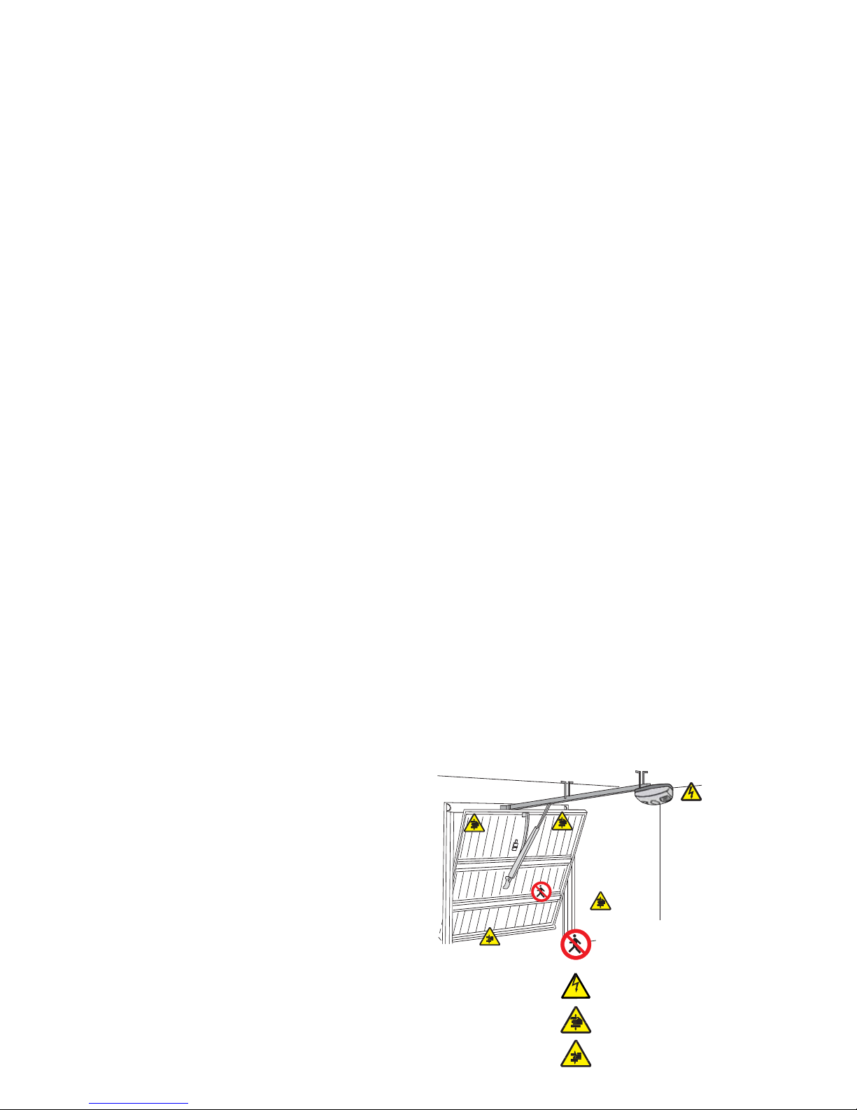
Danger of hand crushing
Danger! High voltage.
No transiting while the barrier
is moving
Danger of foot crushing
Page 4
210115
365
3020 ÷ 4020
p.
4
4 - Manual
FA00047-EN
FA00047-EN v.
2
2- 07/2016 - © Came S.p.A. - The contents of this manual may be changed, at any time, and without notice.
LEGEND
This symbol shows which parts to read carefully.
⚠
This symbol shows which parts describe safety issues
☞
This symbol shows which parts to tell users about.
UNLESS OTHERWISE STATED, THESE OPERATIONS APPLY TO ALL MODELS.
THE MEASUREMENTS, UNLESS OTHERWISE STATED, ARE IN MILLIMETERS.
DESCRIPTION
The operator is made up of a gearmotor, a control board with transformer, a slide guide with either a belt or
chain transmission system, a transmission arm and an ABS casing with display for keypad programming and
an LED courtesy light.
Intended use
The V6000 operator is designed to power overhead and sectional garage door used in homes and apartment
buildings.
Any installation and/or use other than that specified in this manual is forbidden.
Limits to use
Type V6000
Door surface area (m2)9
Maximum height of counterbalanced overhead doors (m) 2.4
Maximum height of spring-balanced overhead doors (m) 3.25
Maximum height of door (m) 3.20
Technical data
Type V6000
Protection rating (IP) 40
Power supply (V - 50/60 Hz) 230 AC
Power supply motor (V) 24 DC
Stand-by absorption (W) 7
Maximum power of the accessories (W) 35
Nominal power (W) 100
Opening speed (m/min) 6
Traction force (N) 600
Operating temperature (°C) -20 ÷ +55
Apparatus class
I
Weight (Kg) 4.9
Dimensions
Page 5

2
1
3
5
7
8
6
4
9 10 11 12 13 14
15
10
9
6
7
8
1
4
2
3
5
p.
5
5 - Manual
FA00047-EN
FA00047-EN v.
2
2- 07/2016- © Came S.p.A. - The contents of this manual may be changed, at any time, and without notice.
Packing list
1. one Operator
2. one Installation Manual
3. two anchoring perforated-plates.
4. one Curved lever
5. Two support braces
6. Three U-shaped braces
7. One guide-fitting brace
8. One door fitting brace
9. Eight self-drilling hexagonal head M6x15 screws
10. One hexagonal M6x80 nut and bolt
11. One (Ø8x25) drive-shaft adapter
12. One 3x20 linchpin
13. One pin
14. Four M8X20 hexagonal screws with washers
and nuts
15. One slide guide
Operator
1. Cover
2. Gearmotor
3. Transformer
4. Control board
5. Power supply cable
Description of parts
Pre-assembled guide package
6. Guide
7. Chain or belt
8. Skid
9. Transmission arm
10. Release cord
Slide guides
001V06001
Chain guide T = 3.02 m.
Counter-balanced overhead doors up to 2.4 m in height
- Counter-balanced overhead doors up to 2.25 m in height
- Sectional* doors up to 2.20 m in height.
001V06002 Chain guide T = 3.52 m.
- Counter-balanced overhead doors up to 2.75 m in height.
- Sectional* doors up to 2.70 m in height.
Page 6

p.
6
6 - Manual
FA00047-EN
FA00047-EN v.
2
2- 07/2016 - © Came S.p.A. - The contents of this manual may be changed, at any time, and without notice.
001V06003 Chain guide T = 4.02 m.
- Spring-balanced overhead doors up to 3.25 m in height.
- Sectional* doors up to 3.20 m in height.
001V06005 Belt guide T = 3.02 m.
Counter-balanced overhead doors up to 2.4 m in height
- Counter-balanced overhead doors up to 2.25 m in height
- Sectional* doors up to 2.20 m in height.
001
001V06006 Belt guide T = 3.52 m.
- Counter-balanced overhead doors up to 2.75 m in height.
- Sectional* doors up to 2.70 m in height.
001V06007
Belt guide T = 4.02 m.
- Spring-balanced overhead doors up to 3.25 m in height
- Sectional* doors up to 3.20 m in height.
Optional accessories
001
001V201 Transmission arm for counter-balanced overhead doors.
001V121 Pull-cord release device to apply onto handle.
☞
For sectional doors, see the APPLICATION EXAMPLES paragraph.
GENERAL INSTRUCTIONS FOR INSTALLING
⚠
Only skilled, qualified staff must install this product.
⚠
If the door is fitted with a pedestrian door, you must also fit a safety switch at the entrance, to stop the
operator from working when the pedestrian door is open.
Preliminary checks
⚠
Before beginning, do the following:
• make sure you have set up a suitable dual pole cut off device along the power supply that is compliant
with the installation rules. It should completely cut off the power supply according to category III surcharge
conditions (that is, with minimum contact openings of 3 mm);
• Setup suitable tubes and conduits for the electric cables to pass through, making sure they are protected
from any mechanical damage;
• make sure that any connections inside the container (ones that ensure continuity to the protection
circuit) are fitted with additional insulation with respect to those of other electrical parts inside:
• make sure that the door is properly balanced. When stopped at any point, it must maintain its position.
Page 7
RX
TX
6
1
5
7
6
2
3
4
8
p.
7
7 - Manual
FA00047-EN
FA00047-EN v.
2
2- 07/2016- © Came S.p.A. - The contents of this manual may be changed, at any time, and without notice.
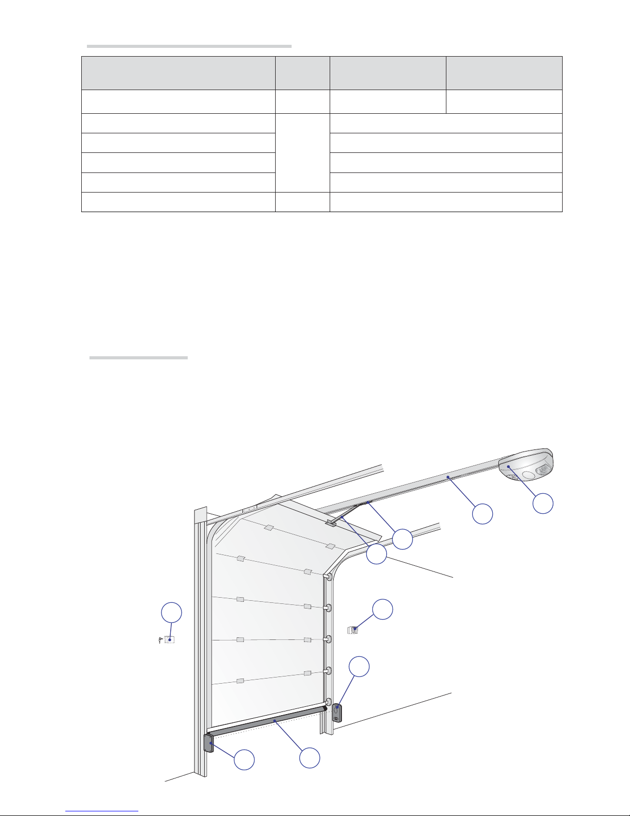
Standard installation
1. Operator with receiver
2. Slide guide
3. Release device
4. Transmission arm
5. Key-switch selector
6. Photocells
7. Keypad
8. Sensitive safety-edge
Cable types and minimum thicknesses
Connection Cable type
Cable length
1 < 15 m
Cable length
15 < 30 m
Control panel power supply 230 V AC H05VV-F
3G x 1.5 mm
2
3G x 2.5 mm
2
Flashing light
FROR CEI
20-22
CEI EN
50267-2-1
2 x 0.5 mm
2
Photocell transmitters 2 x 0.5 mm
2
Photocell receivers 4 x 0.5 mm
2
Command and safety device 2 x 0.5 mm
2
Antenna RG58 max 10 m
If cable lengths differ from those specified in the table, establish the cable sections depending on the actual
power draw of the connected devices and according to the provisions of regulation CEI EN 60204-1.
For multiple, sequential loads along the same line, the dimensions on the table need to be recalculated according
to the actual power draw and distances. For connecting products that are not contemplated in this manual, see
the literature accompanying said products
Page 8
(
H - 100 mm
H
H - 100 mm
H
(
(
M6x80
M6
10 ÷ 20
V201
20 ÷ 30
max 330
p.
8
8 - Manual
FA00047-EN
FA00047-EN v.
2
2- 07/2016 - © Came S.p.A. - The contents of this manual may be changed, at any time, and without notice.
Applicative examples
* single-guide sectional
door
* double-guide sectional
door
SECTIONAL DOOR
COUNTERBALANCED OVERHEAD DOOR,
partially retracting and protruding
SPRING-BALANCED OVERHEAD DOOR,
fully retracting and protruding
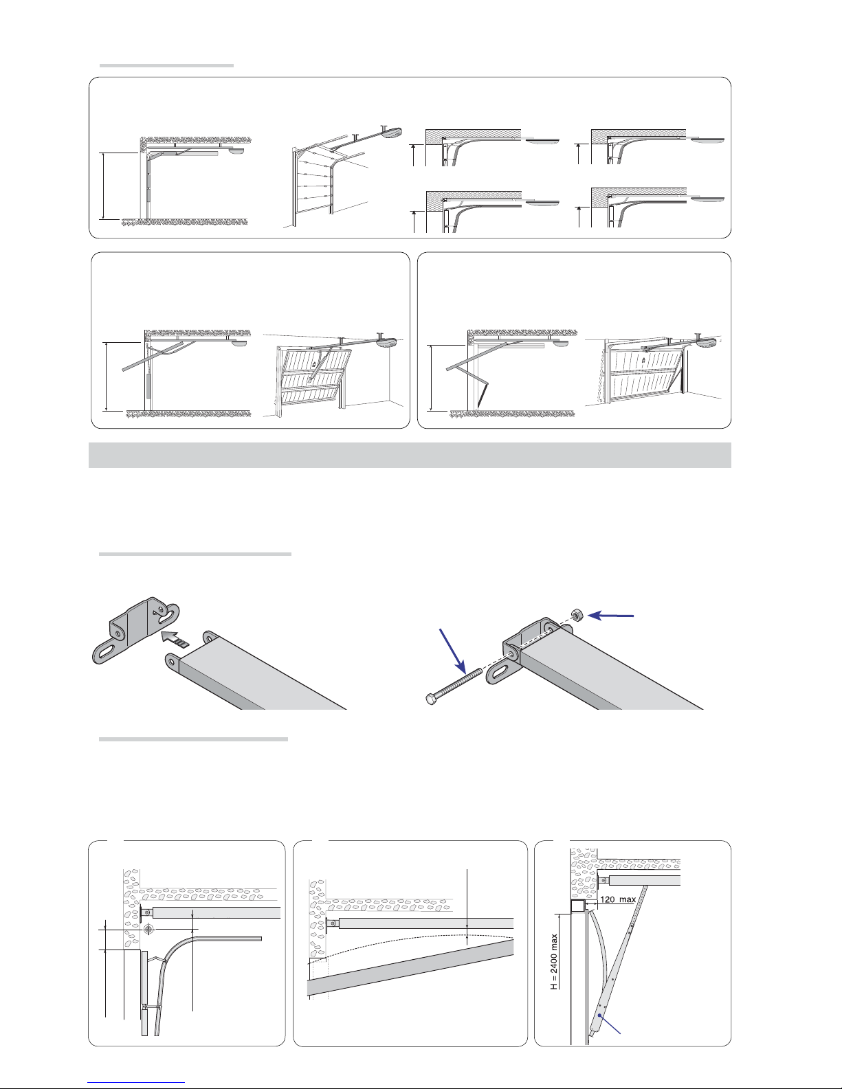
INSTALLATION
⚠
The following illustrations are just examples, in that the space available for fitting the operator and
accessories varies depending on the overall dimensions. It is up to the installer to find the most suitable
solution.
Assembling the traction guide
Fitting the brace to the transmission guide ause the supplied nut and bolt .
Positioning the traction guide
for sectional doors exceeding the overall dimensions of the spring-pole brace.
for overhead doors between 10 and 20 mm from the apex point of the leaf's slide arc.
for partially retracting protruding counter-balanced overhead doors, use the V201 arm (see attached
technical documentation).
Page 9

?
p.
9
9 - Manual
FA00047-EN
FA00047-EN v.
2
2- 07/2016- © Came S.p.A. - The contents of this manual may be changed, at any time, and without notice.
Fastening the traction guide
DFasten the traction guide to the center of the doorway, using suitable screws.
ERaise the guide and position in horizontally to measure the distance to the ceiling, then fasten it.
FInstal the support braces and the U-shaped brace bonto the guide.
Bend the perforated fl at tabs so they fi t snugly and so as to compensate for the distance between the guide
and ceiling.
Fasten the fl at tabs to the support braces and to the U-shaped brace using the supplied screws and washers.
Drill the ceiling so the holes match those on the fl at tabs.
Fasten the fl at tabs to the ceiling using suitable dowels and screws.
Position the transmission arm braceto the door's top rail, perpendicularly to the traction guide and
fasten it using the supplied screws or other suitable fasteners.
If mounting the curved lever fi t it to the transmission arm by using the supplied nuts and bolts
Fitting the transmission arm to the door
Page 10

p.
10
10 - Manual
FA00047-EN
FA00047-EN v.
2
2- 07/2016 - © Came S.p.A. - The contents of this manual may be changed, at any time, and without notice.
Fitting the operator to the guide
Fit the adapter to the drive shaft.
The operator can be fi tted onto the guide: either in standard position or at a right angle .
⚠ If the operator is to be fi tted at a right angle, before installing it, set the micro-switch (see the corresponding paragraph).
Guide
Drive shaft with adapter
Self-drilling 6 x 15 screw
U-shaped brace
Micro
Self-drilling 6 x 15 screw
U-shaped brace
Guide
Drive shaft with adapter
Micro
Page 11

p.
11
11 - Manual
FA00047-EN
FA00047-EN v.
2
2- 07/2016- © Came S.p.A. - The contents of this manual may be changed, at any time, and without notice.
Moving the micro switch
Disconnect the cables of the micro switch and remove the latter.
NRemove the operator's cover and the gable brace. Pull out the electrical cable and fi t it through the hole.
Refi t the cable brace so as to block the hole.
Use a screwdriver to open up the predrilled hole for the electrical cables of the micro switch and fi r the cables
to the micro switch. Fit the micro switch to the operator.
Connect the connectors to the corresponding positions on the micro switch.
⚠ Reconnect the cables as originally connected (NO - C).
Fit the cover back onto the operator.
Page 12

ⓒ
AF
4
2
8
91011
3
1
13
14
16
7
15
6
5
12
p.
12
12 - Manual
FA00047-EN
FA00047-EN v.
2
2- 07/2016 - © Came S.p.A. - The contents of this manual may be changed, at any time, and without notice.
Release the operator
ELECTRICAL CONNECTIONS
⚠
Before powering up the board, cut off the mains
power supply.
Power supply (V - 50/60 Hz): 230 AC
Board functions:
• Movement control and obstacle detection
• Reopening during closing
• Adjustable automatic reclosing time
• Open-stop-close-stop from transmitter and/or from button
• Courtesy light (at each opening command, the
courtesy light stays on for three minutes)
FUSE TABLE
Line fuses (A) 5
LIGHTS
LED courtesy (W) ≤ 1
Description of parts
1. Line fuse
2. Gearmotor
3. Transformer
4. Cables input
5. AF card connector
6. Antenna cable
7. Photocells connection terminal board
8. STOP button connection terminal board
9. Limit switch connection terminal board
10. Encoder connection terminals
11. Display connection terminal board
12. Motor connections
13. Transformer connections
14. Courtesy light connection terminal board
15. Antenna connection terminals
16. Flashing light connection terminal boards
Release
To release the operator, pull down on the ⓒcord.
Locking
To lock the operator back up, use the transmitter or the control button.
Page 13

RX
TX
p.
13
13 - Manual
FA00047-EN
FA00047-EN v.
2
2- 07/2016- © Came S.p.A. - The contents of this manual may be changed, at any time, and without notice.
When CLOSING: inverts the
direction of travel until opening is
complete.
After three consecutive inversions,
the door stays open and excludes
the automatic closing: to close,
either use the transmitter or button.
When OPENING:the door stops. To
resume movement, either press a button
or use the transmitter.
Movement control and obstacle detection
Power supply
⚠The operator is supplied with an electrical cable (L = 1.2 m) with an already connected Shuko plug.
Command and control devices
Stop button (NC contact). Enables the door to stop and excludes the automatic closing. To resume movement
either press the control button or any other control device.
If a device is connected, remove the bridge
OPEN-STOP-CLOSE-STOP
function from control device (NO
contact).
If a device is connected, remove the bridge
Safety devices
Page 14

p.
14
14 - Manual
FA00047-EN
FA00047-EN v.
2
2- 07/2016 - © Came S.p.A. - The contents of this manual may be changed, at any time, and without notice.
(NC) contact for reopening during closing.
Input for safety devices such as photocells, sensitive safety-edges and other devices that are compliant with EN 12978
standards.
During closing, opening this contact triggers an inversion of
movement until the door is completely open.
If a device is connected, remove the bridge
Preparing for programming
Manually hook up the door to the skid.
Power up the operator. After emitting a sound signal, the
control board is ready for programming.
Remove the transparent panel to access the programming
keys.
⚠ Memorizing (function 5) must always be the last phase of programming, otherwise the settings will not
be saved.
In the case of errors, cut off and the power up again the mains power and reprogram.
PROGRAMMING DEVICE -
Description of keys
Menu adjusting
and browsing key
Menu adjusting
and browsing key
Transmitter
memorizing
key
Menu access and
save changes key
Display for programming and monitoring the
operator's operation
L = normal
operation
F = obstacle
detection
H = Encoder error
A = Active
photocell
Legend of symbols
⚠ Some functions must be set so that the operator can work, others, on the other hand, are optional
Flashing light (contact rated for: 24 V - 25 W max).
It fl ashes during opening and closing.
Signaling devices
Page 15

5
p.
15
15 - Manual
FA00047-EN
FA00047-EN v.
2
2- 07/2016- © Came S.p.A. - The contents of this manual may be changed, at any time, and without notice.
Obligatory functions
Establishing the opening limit-switch points
⚠Respect the order of settings of the limit switches shown in this manual.
With the operator idle
1
Press P for about fi ve
seconds.
4
Press +.
2
The operator emits a sound
signal and 1 appears.
5
Let the door reach the
position you want.
3
Press P again,
1 fl ashes
6
Press P to save the
procedure.
Establishing the closing limit-switch points
1 Press +, 2 appears. 4
Let the door reach the closing
position you want.
2 Press P, 2 fl ashes. 5
Press P for saving the
procedure.
3 Press -.
Checking the travel self-learning
1
Press +, 3 appears. 4 Press P.
2
Press P, 3 fl ashes. 5
The door reaches the closing
limit switch.
3
The door reaches the
opening limit switch.
Page 16

5
p.
16
16 - Manual
FA00047-EN
FA00047-EN v.
2
2- 07/2016 - © Came S.p.A. - The contents of this manual may be changed, at any time, and without notice.
Memorizing the programming
⚠
It is OBLIGATORY to conclude the programming procedures with this function so as not to lose
any saved settings!
Press + to select 5.
Press P. The display segments rotate clockwise.
The programming has been memorized.
1 Press P for about fi ve seconds, 1 appears.
2
Press + and select 4.
3
Press P, appears .
4 Press + o - to set the suitable sensitivity level.
5
Minimum level of Maximum sensitivity
6 Press P to save the procedure.
Adjusting the sensitivity
⚠The door must be properly balanced. If the sensitivity is too low it could cause the door to malfunction.
By default, the sensitivity is set to a medium level. To increase or reduce sensitivity:
The last phase of programming must always be memorized (function 5).
Once memorization is complete, perform two opening and closing cycles to confi rm that the settings have
been saved.
Page 17

5
5
p.
17
17 - Manual
FA00047-EN
FA00047-EN v.
2
2- 07/2016- © Came S.p.A. - The contents of this manual may be changed, at any time, and without notice.
1
Press P for about fi ve
seconds, 1 appears.
4
Press + and select 1. The
alarm is now activated.
2 Press + and select 6 5
Press P to save the
procedure.
3 Press P, 0 appears
Adjusting the waiting time before automatic the closing
By default, this function is deactivated. To activate it:
1 Press P for about fi ve seconds, 1 appears.
2
Press + and select 7.
3 Press P, 0 appears.
4
Press + and select 1. The automatic closing is active and the waiting
time is 30 seconds.
To change the duration of the waiting time before the automatic closing, either press + or -.
5
60 seconds 90 seconds 120 seconds
150
seconds
180 seconds 210 seconds 240 seconds
6
Press P to save the
procedure
Memorizing (function 5) must always be the last phase of programming, otherwise the settings will
not be saved.
Optional functions
By default, this function is deactivated; by activating the alarm function, the operator emits a long sound
signal if the door stays open for more than 10 minutes. To activate it:
Setting the alarm
Memorizing (function 5) must always be the last phase of programming, otherwise the settings will not be
saved.
Page 18

AF
TOP TAM
AF43S / AF43SM
p.
18
18 - Manual
FA00047-EN
FA00047-EN v.
2
2- 07/2016 - © Came S.p.A. - The contents of this manual may be changed, at any time, and without notice.
Only for the AF43S / AF43SM: radio-frequency card:
- position the jumper as shown in the second series of transmitters being used.
⚠The operator emits a sound signal for 20 seconds before the door starts to automatically close. Simultaneously, the courtesy light fl ashes. When the door starts closing, the operator emits a sound signal and the courtesy
light is on. When the door is closed, the operator does not emit any sound signal and the courtesy light stays
on for three minutes.
ACTIVATING THE RADIO CONTROL
Radio frequency card
Fit the AF card into the connector on the control board.
Before fitting the AF card, you MUST CUT OFF THE MAINS POWER SUPPLY
Additional external antenna
Disconnect the internal antenna and connect the external one to
the corresponding terminals on the control board.
Page 19

p.
19
19 - Manual
FA00047-EN
FA00047-EN v.
2
2- 07/2016- © Came S.p.A. - The contents of this manual may be changed, at any time, and without notice.
Memorizing the transmitters
You can memorize up to 16* di erent codes/users. When the operator is idle:
1 Press and keep pressed S until
2
0 appears on the left side of the screen. The segments of the 0 on the left side of
the screen rotate clockwise.
Release the S key.
3
Consecutively press twice the key that you want to memorize.The control unit will
BEEP to confi rm that the transmitter has been memorized.
⚠* When you try to memorize the 17th code (or transmitter) the courtesy light flashes slowly five times to
signal that the memory is full.
Deleting transmitters
1
Press and keep pressed the S until
2
the 0 appears on the left of the display. The segments of the 0 on the right of the display turn
clockwise.
3
When the 0 on the left disappears, release the S key: the transmitters have been deleted.
Page 20

p.
20
20 - Manual
FA00047-EN
FA00047-EN v.
2
2- 07/2016 - © Came S.p.A. - The contents of this manual may be changed, at any time, and without notice.
TROUBLESHOOTING
ISSUES CHECKS AND FIXES
• The operator neither opens nor closes • Check the power supply and line fuses
• The (1-2) NC safety contact is open
• The operator opens but does not close • The N.C. safety contact (2-C1) is open
• Check the proper direction of the door travel
• Check the balancing of the overhead garage-door
• The operator closes but does not open • Check the balancing of the overhead garage-door
• The operator does not perform the
automatic closing
• Check that the A.C.T. trimmer is not set to minimum
• Check the proper direction of the door travel
• The transmitter does not work • Check the bridging on the AF card, cut off/power up again
• Memorize the transmitter again
• The operator pushes too hard • Adjust the sensitivity
• The operator pushes to weakly or inverts
the direction of travel
• Adjust the sensitivity
• Eliminate all mechanical friction
• Check the door balancing
• Check the tautness of the belt/chain
• Only one transmitter works • Enter (or duplicate) the same code in all the transmitters
• The photocell is not working • The N.C. safety contact (2-C1) is open
• Check proper functioning of the photocell
• The PROGRAMMING LED flashes rapidly • The N.C. safety contact (2-C1) is open
• The Encoder doesn't work: cut off the power to the control
board, then power it up again
• Wrong Encoder connection: check connections
• The PROGRAMMING LED stays lit • NC control button instead of NO (2-7)
• The POWER-ON alerting LED is off • Checkthe power supply and line fuses
• The (1-2) NC safety contact is open
• The operator does not work with the
emergency batteries
• Deactivate the obstruction detection function by using the
DIP-switches
• Check the batteries
• Respect the polarities of the photocells and accessories
• The operator inverts the travel direction at
the limit switch
• Check the proper direction of the door travel
• Eliminate all mechanical friction
• Check the door balancing
• The operator starts too slowly • Eliminate all mechanical friction
• Check the door balancing
• Check the tautness of the belt/chain
Page 21

p.
21
21 - Manual
FA00047-EN
FA00047-EN v.
2
2- 07/2016- © Came S.p.A. - The contents of this manual may be changed, at any time, and without notice.
MAINTENANCE
Periodic maintenance
☞ Before doing any maintenance, cut off the mains power supply, to prevent any hazardous situations resulting from the
door's unexpected movement.
Periodic maintenance log kept by users (every six months)
Date Notes Signature
Page 22

p.
22
22 - Manual
FA00047-EN
FA00047-EN v.
2
2- 07/2016 - © Came S.p.A. - The contents of this manual may be changed, at any time, and without notice.
Fitter's stamp Name of operator
Job performed on (date)
Technician's signature
Requester's signature
Job performed ________________________________________________________
__________________________________________________________________
___________________________________________________________________
_________________
Extraordinary maintenance
⚠
The following table is for logging any extraordinary maintenance jobs, repairs and improvements performed
by specialized contractors.
Any extraordinary maintenance jobs must be done only by specialized technicians.
Extraordinary maintenance log
Page 23

p.
23
23 - Manual
FA00047-EN
FA00047-EN v.
2
2- 07/2016- © Came S.p.A. - The contents of this manual may be changed, at any time, and without notice.
DISMANTLING AND DISPOSAL
☞
CAME S.p.A. applies a certified Environmental Management System at its premises, which is compliant
with the UNI EN ISO 14001 standard to ensure the environment is safeguarded. Please continue safeguarding
the environment. At CAME we consider it one of the fundamentals of our operating and market strategies.
Simply follow these brief disposal guidelines:
DISPOSING OF THE PACKAGING
The packaging materials (cardboard, plastic, and so on) should be disposed of as solid household waste,
and simply separated from other waste for recycling. Always make sure you comply with local laws before
dismantling and disposing of the product.
DO NOT DISPOSE OF IN NATURE!
DISMANTLING AND DISPOSAL
Our products are made of various materials. Most of these (aluminum, plastic, iron, electrical cables) is
classified as solid household waste. They can be recycled by separating them before dumping at authorized city
plants. Whereas other components (control boards, batteries, transmitters, and so on) may contain hazardous
pollutants. These must therefore be disposed of by authorized, certified professional services. Before disposing,
it is always advisable to check with the specific laws that apply in your area.
DO NOT DISPOSE OF IN NATURE!
PERTINENT REGULATIONS
This product complies with the law.
Page 24

Came S.p.A.
Came S.p.A.
Via Martiri Della Libertà, 15 Via Cornia, 1/b - 1/c
31030
Dosson di Casier
Dosson di Casier
Treviso
Treviso - Italy
33079
Sesto al Reghena
Sesto al Reghena
Pordenone
Pordenone - Italy
(+39) 0422 4940
(+39) 0422 4941
(+39) 0434 698111
(+39) 0434 698434
www. came.com
www. came.com
English - Manual FA00047-EN v. 2 - 07/2016 - © Came S.p.A.
The contents of this manual may change, at any time, and without notice.
 Loading...