

Page 1
CANCELLI AUTOMATICI
10
11
11
SERIE BX |
BX SERIES |
SERIE BX
BX-A / BX-B
Automazioni per cancelli scorrevoli
Automation systems for sliding gates
Automatización para puertas correderas
4
1
1
2
2
3
3
9
5
5
4
4
10
10
9
9
6
6
7
Documentazione
Tecnica
ESPAÑOL
S17
/
rev. 2.1
07/2002
ENGLISH
/
©
CAME
CANCELLI
AUTOMATICI
119BS17-1
ITALIANO
8
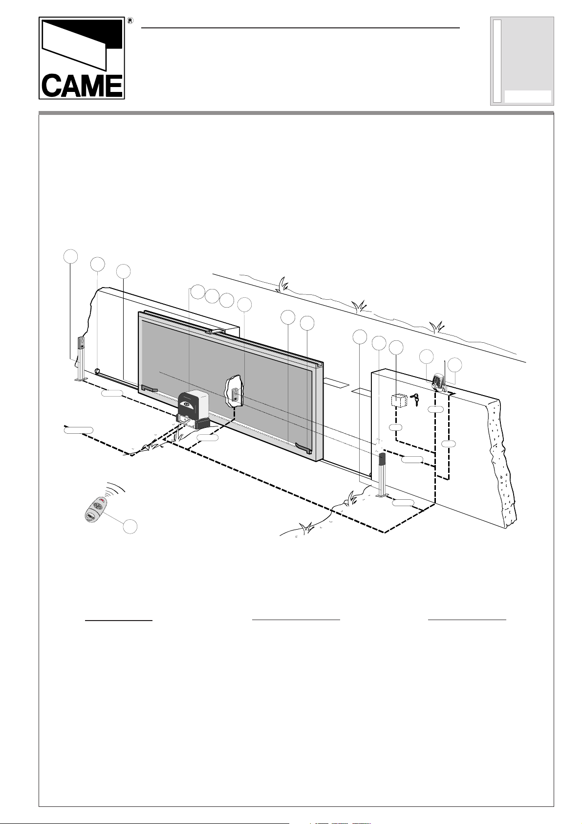
2 x 1 - TX
3 x 1.5 / 230V
3 x 1.5 / 230V
12
Impianto tipo
1 - Gruppo BX
2 - Scheda comando
3 - Ricevitore radio
4 - Alette finecorsa
5 - Cremagliera
6 - Selettore a chiave
7 - Lampeggiatore di movimento
8 - Antenna di ricezione
9 - Fotocellule di sicurezza
10 - Colonnina per fotocellula
11 - Fermo anta
12 - trasmettitore radio
4 x 1 - RX
Standard installation
1 - BX unit
2 - Control board
3 - Radio receiver
4 - Limit-switch tabs
5 - Rack
6 - Key-operated selector switch
7 - Flashing light indicating door movement
8 - Antenna
9 - Safety photocells
10 - Photocell column
11 - Closure stop
12 - Radio transmitter
2 x 1.5
2 x 1.5
2 x 1
3 x 1
RG58
RG58
2 x 1 - TX
2 x 1 - TX
4 x 1 - RX
4 x 1 - RX
Instalación tipo
1 - Conjunto BX
2 - Tarjeta de mando
3 - Radiorreceptor
4 - Aletas de tope
5 - Cremallera
6 - Selector mediante llave
7 - Lámpara intermitente de movimiento
8 - Antena receptora
9 - Fotocélulas de seguridad
10 - Columna para fotocélula
11 - Tope puerta
12 - transmisor
Page 2
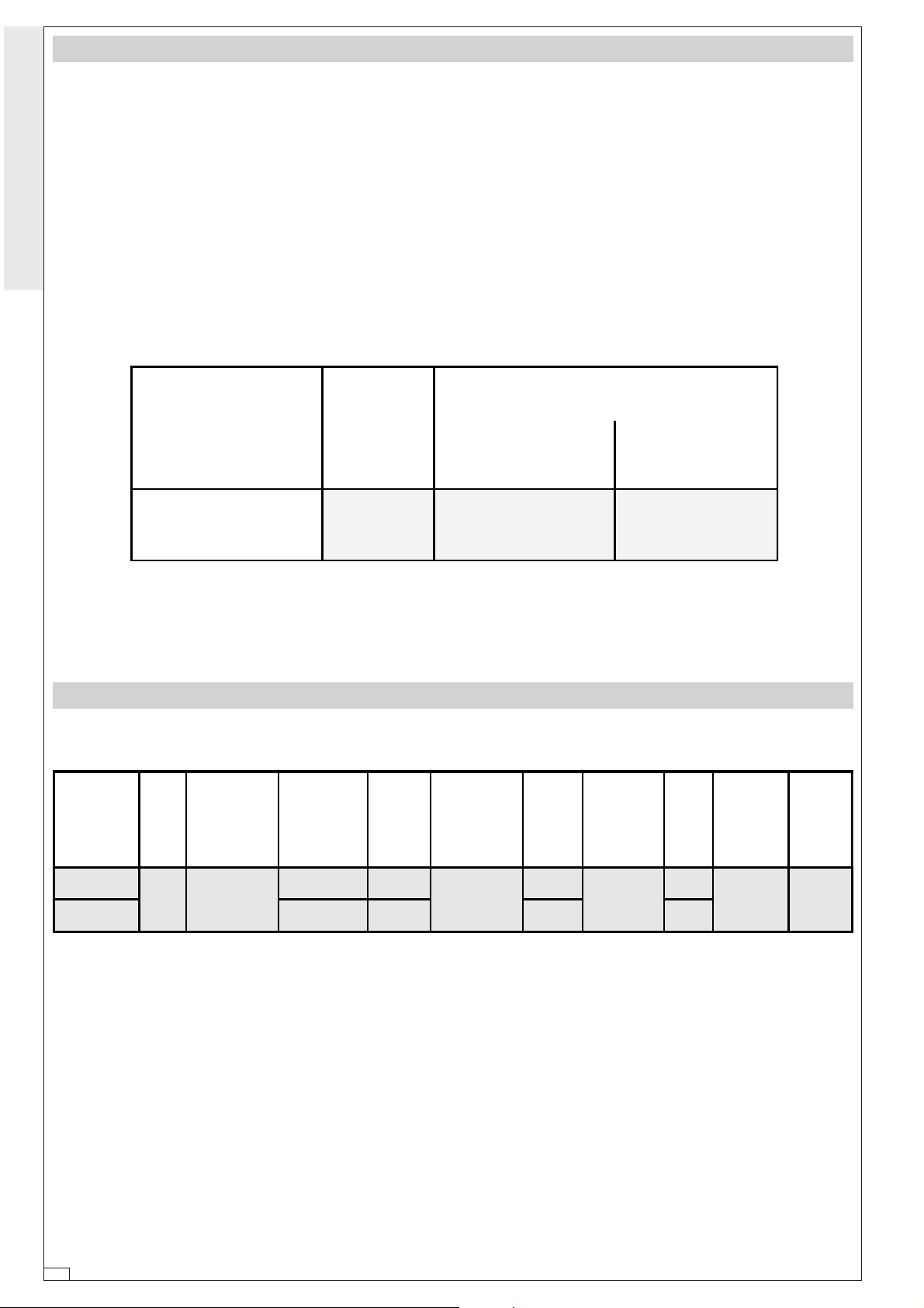
CARATTERISTICHE GENERALI -
GENERAL SPECIFICATIONS
- CARACTERÍSTICAS GENERALES
- Progettato e costruito interamente
dalla CAME Cancelli automatici S.p.A.
- Grado di protezione IP54.
- Garantito 24 mesi salvo manomissioni.
ITALIANO • ENGLISH • ESPAÑOL
Peso massimo cancello
Gate maximum weight
Peso máximo puerta
- Designed and constructed entirely by
CAME Cancelli automatici S.p.A.
- IP 54 protection rating.
-24 mounth guarantee; guarantee void if
unit is tampered with.
- Diseñado y construido totalmente por
CAME Cancelli Automatici S.p.A.
- Grado de protección IP54.
-Garantia de 24 meses salvo manipulaciones.
BX-A BX-B
per uso residenziale per uso intensivo
for residential use for intensive use
para uso residencial para uso intensivo
400 Kg 800 Kg 600 Kg
CARATTERISTICHE TECNICHE -
MOTO-
RIDUTTORE
GEARMOTOR WEIGHT POWER SUPPLY CURRENT POWER DUTY CYCLE
MOTOR-
REDUCTOR
BXA
BXB 2,4A 300W * 32 Nm 800 N
* Ottenuta mediante quadro comando CAME
PESO ALIMENTAZIONE ASSORBIMENTO POTENZA
PESO ALIMENTACION ABSORBENCIA POTENCIA
15 Kg 230V a.c.
TECHNICAL CHARACTERISTICS -
INTERMITTENZA
LAVORO
INTERMITENCIA
TRABAJO
2,6A 200W
30 %
* Obtained with CAME control panel
CARACTERISTICAS TECNICAS
COPPIA
MAX
TORQUE
PA RE JA
(MOTOR)
* 24 Nm
RAPPORTO DI
RIDUZIONE
REDUCTION
RATIO
RELACION DE
REDUCCION
1/33
* Se obtiene mediante el cuadro de mando CAME
SPINTA
PUSH
EMPUJE
300 N
VELOCITA'
MAX
MAX
SPEED
VELOCIDAD
MAX
10 m/min. 20 µF
CONDEN-
SATORE
CAPACITOR
CONDEN-
SADOR
-2-
Page 3
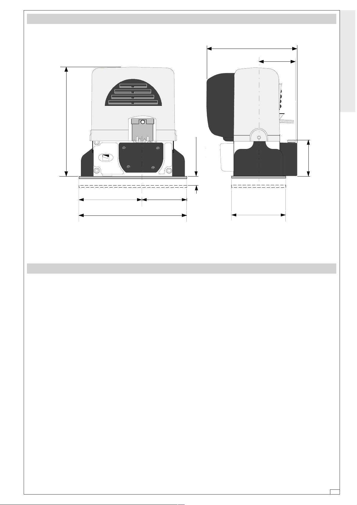
310
MISURE D'INGOMBRO -
OVERALL DIMENSIONS
- MEDIDAS
240
105
ITALIANO • ENGLISH • ESPAÑOL
PRIMA DI INSTALLARE ...... -
- Controllare che l'anta sia rigida e compatta e che le ruote di scorrimento siano in buono stato e adeguatamente
ingrassate.
- La guida a terra dovrà essere ben fissata al suolo, completamente in superficie in tutta la sua lunghezza e priva di
irregolarità che possano ostacolare il
movimento del cancello.
- I pattiniguida superiori non devono creare attriti.
- Prevedere un fermo anta in apertura e
uno in chiusura ed il percorso dei cavi
elettrici come da impianto tipo.
22 max.
125165
290
BEFORE INSTALLING .....
- ANTES DE INSTALAR EL AUTOMATISMO...
- The gate must be sufficiently rigid and
solid.
- The wheels on which the gate slide must
be in perfect condition and adequately lubricated.
- The wheel guide must be firmly attached
to the ground, completely exposed, and
without any dips or irregular sections
which might hinder the movement of the
gate.
- The upper guide must allow for the correct amount of play in order to guarantee
smooth and silent movement of the gate.
- Opening and closure stops must be installed.
- The wiring must be routed as specified by
the control and safety requirements.
105
150
- La hoja de la puerta debe estar suficientemente rigida y compacta.
- Las ruedas de deslizamiento deben
estar perfecta y engrasadas adecuadamente.
- La guia de deslizamiento debe estar
bien fijada en el suelo, sobresaliendo
a lo largo de su entera longitud, sin
huecos ni irregularidades (que podrian
obstaculizar el movimiento de la puerta).
- La guia superior debe tener el justo
juego con la puerta metálica (para garantizar un movimiento regular y silencioso).
- Disponer un tope para apertura y el cierre.
- Disponer un conducto para los cables
eléctricos que cumpla con las disposiciones de mando y seguridad.
-3-
Page 4

FISSAGGIO BASE MOTORE -
MOTOR TO BASE ANCHORAGE
- FIJACIÓN BASE MOTOR
ITALIANO • ENGLISH • ESPAÑOL
Cavi
Cables
Cables
Cremagliera
Rack-limit
Cremallera
Anta cancello
Gate wing
Puerta
75 mm.
Struttura fissa
Wall
Estrctura fija
50 mm.
105 mm.
Piazzola in cemento
Concrete base
plataforma de cemento
- Inserire le viti nella piastra di ancoraggio bloccandole con un dado, ed estrarre le zanche preformate verso il basso.
- Predisporre, dimensionandola in base
alle misure del motoriduttore, una piazzola in cemento (si consiglia di farla
sporgere dal terreno di circa 50 mm.)
con annegata la piastra di ancoraggio
e relative zanche sulla quale sara' fissato il gruppo.
- La base di fissaggio dovrà risultare
perfettamente in bolla, pulita in tutte le
sue estremità, con il filetto delle viti
completamente in superfice.
Piastra di ancoraggio / Zanche
Fixing plate / Anchor stays
Placa de fijación / arras de fijción
- Install the screws in the anchor plate and
fasten them with a nut, then bend the preformed clamps downwards.
- Construct a cement foundation that is
large enough to accomodate the gear
motor (it is a good idea to protrude 50
mm. from the ground). When pouring the
foundation, embed the gear motor anchor plate and the relative clamps in the
cement.
- The anchor bolts should be embedded in
the concrete in the positions indicated;
the drive unit is then attached to this bots.
The anchor plate must be perfectly level
and absolutly clean; the bolts threads
must be completly exposed.
- Introducir los tornillos en la placa de
anclaje, bloqueándolos con una tuerca, y doblar las palancas preformadas
hacia abajo.
- Preparar, dándole las dimensiones
adecuadas en función de las medidas
del motorreductor, una plataforma de
cemento (se aconseja dejarla sobresalir del suelo aprox. 50 mm.) con la
placa de enclaje embedida y con las
correspondientes varillas, que permitrá la fijación del grupo.
- La base de fijación debe estar perfectamente nivelada, limpia en todos sus
extremos, con la rosca de los tornillos totalmente in superficie.
N.B.: Dalla stessa dovranno emergere i
tubi flessibili per il passaggio dei cavi di
collegamento elettrico.
-4-
N.B.: The flexible tubes for the electrical
wiring must be embedded in the base and
protude in the correct position.
N.B.: De ésta deben sobresilar los tubos flexibles para el paso de los cables
para las conexiones eléctricas.
Page 5

POSA DEL GRUPPO -
Regolazione orizzontale e fissaggio
Horizontal Adjustement unit and achorage
Regulación horizontal y fijación
UNIT INSTALLATION -
COLOCACIÓN DEL GRUPO
Accoppiamento pignone-cremagliera con gioco 1÷2 mm
Rack-to-pinion coupling whit 1÷2 mm. clearance
Acoplamiento piñon -cremaliera 1÷2 mm. de juego
1÷2 mm.
ITALIANO • ENGLISH • ESPAÑOL
5÷10 mm.
Ingresso cavi
Cable entrances
Entrada cables
Nella fase preliminare di posa, i piedini
dovranno sporgere di 5-10mm per permettere allineamenti, fissaggio della
cremagliera e regolazioni successive.
L'accoppiamento esatto con la linea di
scorrimento del cancello è ottenibile dal
sistema di regolazione integrale (brevettato) composto da:
- le asole che permettono la regolazione
orizzontale;
- i piedini filettati in acciaio che permettono la regolazione verticale e la messa in bolla;
- le piastrine e i dadi di fissaggio che
rendono solidale l'aggancio del gruppo
alla base.
Regolazione verticale - messa in bolla
Vertical adjustment and unit leveling
regulación vertical y nivelación
During the initial phase of installation, the
feet should protrude by 5-10mm in order
to allow for alignment, anchorage of the
rack and further adjustments.
Perfect alignment with the guide rail is
made possible by the (patented) builtin
regulation system, which consists of:
- slots for horizontal adjustment;
- threaded steel feet for vertical adjustment and levelling;
- plates and bolts for anchorage to the
base.
En la fase previa del emplazamiento, los
pies deben sobresalir 5-10mm para
consentir la alineación, la fijación de la
cremallera y las regulaciones sucesivas.
El acoplamiento exacto con la linea de
deslizamiento de la puerta metálica se
obtiene mediante el sistema de regulación integral (patentado) que consta de:
- los agujeros ovalados que consienten
la regulación horizontal;
- las tuercas de acero que permiten la
regulación vertical y la nivelación;
- las placas y las tuercas de fijación que
hacen solidario el enganche del conjunto con la base.
-5-
Page 6

ITALIANO • ENGLISH • ESPAÑOL
FISSAGGIO CREMAGLIERA -
ATTACHING THE RACK/LIMIT
- FIJACIÓN DE LA CREMALLERA
Fissare la cremagliera sul cancello come
segue:
- appoggiare la cremagliera sul pignone
del motoriduttore e far scorrere manualmente il cancello fissando la cremagliera in tutta la sua lunghezza;
- ultimata l'operazione di fissaggio della
cremagliera, regolare i piedini (servendosi di un cacciavite) in modo da
ottenere il giusto giuoco tra pignone e
cremagliera (1-2 mm).
N.B. : Questo evitera' che il peso del
cancello vada a gravare sul gruppo.
- Se la cremagliera é gia' fissata, procedere direttamente alla re-golazione
dell'accoppiamento pigno-necremagliera.
- Eseguite tutte le regolazioni, fissare il
gruppo stringendo i dadi di fissaggio.
Attach the rack to the gate as described
below:
- Position the rack on the pinion of the
gearmotor and slide the gate manually in
order to attach the rack along its entire
length;
- when the rack is attached to the gate,
adjust the feet using a screwdriver until
the play between the pinion and the rack
is correct (1-2 mm.).
N.B.: This position ensures that the weight
of the gate does not rest on the gearmotor.
- If the rack is already attached, proceed
directly to the adjustment of the rack/
pinion coupling.
- When the necessary adjustment have
been completed, fasten the unit in position by tightening the two anchor bolts.
Colocar el motorreductor en la posición
para el desbloqueo.
- Fijar la cremallera en la puerta metálica como se indica a continuación.
- Apoyar la cremallera en el piñón motorreductor y deslizar manualmente la
puerta metálica fijando la cremallera
a lo largo de su entera longitud.
- Finalizadas las operaciones para la fijacion de la cremallera, regular los
pies (por medio de un destornillador)
de modo que se obtenga el justo juego
entre el piñón y la cremallera (1-2 mm).
N.B. Esto hace que el peso de la puerta
metálica no cargue sobre el conjunto.
- Si la cremallera ya ha sido fijada, hay
que regular el acoplamiento piñón cremallera.
- Una vez realizados los ajuste, fijar el
conjunto cerrando las dos tuercas de
fijación.
-6-
Page 7

FISSAGGIO FINECORSA -
CAME
ATTACHING THE SWITCH TABS -
FIJACIÓN DE LA ALETAS DE TOPE
ITALIANO • ENGLISH • ESPAÑOL
Posizionare sulla cremagliera le alette
finecorsa che determineranno, con la
loro posizione, la misura della corsa.
Nota: evitare che il cancello vada in
battuta contro il fermo meccanico, sia
in apertura che in chiusura.
SBLOCCO MOTORIDUTTORE -
- Per aprire lo sportellino inserire la chiave, spingerla e ruotala in senso orario.
- Sbloccare quindi il motoriduttore ruotando la manopola nella direzione indicata.
Position the limitsswitch tabs (whose positions determine the limits of gate travel)
on the rack.
Note: do not allow the gate to strike the
mechanical stops in the open or closed
positions.
GEAR RELEASE
- DESBLOQUEO MOTORREDUCTOR
- To open the access door, insert the key,
push down and rotate clockwise.
- Now, release the gear motor by rotating
the knob in the direction shown.
Colocar en la cremallera las aletas de
final de carrera que determinan, con su
posición, la medida de la carrera.
Nota: evitar que la puerta choque contro el tope mecánico, tanto en la apertura como en el cierre.
- Para abrir la portezuela introducir la
llave, empujarla y girarla en sentido
horario.
- Desbloqear el motorreductor girando
la manilla en la dirección indicada.
ATTENZIONE:
l'apertura dello sportellino di sblocco
impedisce il funzionamento del motore.
ATTENTION:
the opening of the unblock panel arrests
the motor.
Blocco
Engage
Bloqueo
CAME
Sblocco
Release
Desbloqueo
ATENCIÓN:
la apertura de la tapa de desbloqueo,
impide el funcionamiento del motor.
-7-
Page 8

DICHIARAZIONE DEL FABBRICANTE
Allegata alla documentazione tecnica (l’originale della Dichiarazione è disponibile a richiesta)
I Rappresentanti della
CAME Cancelli Automatici S.p.A.
via Martiri della Libertà, 15
31030Dosson di Casier - Treviso - ITALYtel
(+39) 0422 4940 - fax (+39) 0422 4941
internet: www.came.it - e-mail: info@came.it
Dichiarano sotto la propria responsabilità che i/il prodotto/i denominato/i ...
BXA • BXB
B4336 • B4337 • CCT • CGIU • CGZ • CGZF • CGZS
BRC5 • BRC10 • BRC15 • BRCP • BSF • R001
… sono conformi alle disposizioni legislative Nazionali che traspongono le seguenti Direttive
Comunitarie (dove specificatamente applicabili):
DIRETTIVA MACCHINE 98/37/CE
DIRETTIVA BASSA TENSIONE 73/23/CEE - 93/68/CEE
DIRETTIVA COMPATIBILITÀ ELETTROMAGNETICA 89/336/CEE - 92/31/CEE
DIRETTIVA R&TTE 1999/5/CE
Ai sensi dell’Allegato II B della Direttiva Macchine 98/37/CE
Documentazioni tecniche specifiche dei prodotti sono disponibili a richiesta!
Inoltre, dichiara che il/i prodotto/i, oggetto della presente dichiarazione, sono costruiti nel rispetto
delle seguenti principali norme armonizzate:
EN 292 PA RT E 1ª E 2ª SICUREZZA DEL MACCHINARIO.
EN 12453 CHIUSURE INDUSTRIALI, COMMERCIALI …
EN 12445 CHIUSURE INDUSTRIALI, COMMERCIALI …
EN 60335 - 1 SICUREZZA NEGLI APPARECCHI AD USO DOMESTICO ...
EN 60204 - 1 SICUREZZA DEL MACCHINARIO.
EN 50081 - 1 E 2COMPATIBILITÀ ELETTROMAGNETICA.
EN 50082 - 1 E 2COMPATIBILITÀ ELETTROMAGNETICA.
AVVERTENZA IMPORTANTE!
È vietato mettere in servizio il/i prodotto/i, oggetto della presente dichiarazione, prima del
completamento e/o incorporamento, in totale conformità alle disposizioni della Direttiva
Macchine 98/37/CE
RESPONSABILE TECNICO
Sig. Gianni Michielan
Data della presente dichiarazione 07/12/2001
Firma dei Rappresentanti
PRESIDENTE
Sig. Paolo Menuzzo
MANUFACTURER’S DECLARATION
Enclosed with the technical documentation (the original copy of the Declaration is available on request)
The representatives of
CAME Cancelli Automatici S.p.A.
via Martiri della Libertà, 15
31030 Dosson di Casier - Treviso - ITALY
tel (+39) 0422 4940 - fax (+39) 0422 4941
internet: www.came.it - e-mail: info@came.it
Hereby declare, under their own respons ibility, that the product/s called ...
As per Enclosure II B of Machinery Directive 98/37/CE
BXA • BXB
B4336 • B4337 • CCT • CGIU • CGZ • CGZF • CGZS
BRC5 • BRC10 • BRC15 • BRCP • BSF • R001
… comply with the Italian National Legal Provisions that transpose the
following Community Directives (where specifically applicable):
MACHINERY DIRECTIVE 98/37/CE
LOW VOLTAGE DIRECTIVE 73/23/EEC - 93/68/EEC
LECTROMAGNETIC COMPATIBILITY DIRECTIVE 89/336/EEC - 92/31/EEC
R&TTE DIRECTIVE 1999/5/CE
Specific technical documentation on the products is available on request!
DECLARACION DEL FABRICANTE
De conformidad con el Anexo II B de la Directiva de Máquinas 98/37/CE
Los Representantes de la compañía
CAME Cancelli Automatici S.p.A.
via Martiri della Libertà, 15
31030 Dosson di Casier - Treviso - ITALY
tel (+39) 0422 4940 - fax (+39) 0422 4941
internet: www.came.it - e-mail: info@came.it
Declaran bajo su responsabilidad que el/los producto/s denominado/s ...
BXA • BXB
B4336 • B4337 • CCT • CGIU • CGZ • CGZF • CGZS
BRC5 • BRC10 • BRC15 • BRCP • BSF • R001
… cumplen con las disposiciones legislativas nacionales que trasponen las siguientes
Directivas Comunitarias (donde específicamente aplicables):
DIRECTIVA DE MÁQUINAS 98/37/CE
DIRECTIVA DE BAJA TENSIÓN 73/23/CEE - 93/68/CEE
DIRECTIVA DE COMPATIBILIDAD ELECTROMAGNÉTICA 89/336/CEE - 92/31/CEE
DIRECTIVA R&TTE 1999/5/CE
Date of the present declaration 07/12/2001
Also, they furthermore represent and warrant that the product/s that are the subject of the present
Declaration are manufactured in the respect of the following main harmonized provisions:
EN 292 PAR T 1 AND 2MACHINERY SAFETY.
EN 12453 INDUSTRIAL, COMMERCIAL AND OTHER CLOSING MECHANISMS.
EN 12445 INDUSTRIAL, COMMERCIAL AND OTHER CLOSING MECHANISMS.
EN 60335 - 1 SAFETY IN APPARATUSES FOR HOME USE.
EN 60204 - 1 MACHINERY SAFETY.
EN 50081 - 1 AND 2ELECTROMAGNETIC COMPATIBILITY.
EN 50082 - 1 AND 2ELECTROMAGNETIC COMPATIBILITY.
IMPORTANT CAUTION!
It is forbidden to market/use product/s that are the subject of this declaration before completing and/
or incorporating them in total compliance with the provisions of Machinery Directive 98/37/CE
Signatures of the Representatives
TECHNICAL MANAGER
Mr. Gianni Michielan
Fecha de la presente declaración 07/12/2001Adjunta a la documentación técnica (el original de la Declaración está disponible previa petición)
Los productos objeto de esta declaración están fabricados respetando las siguientes normas
armonizadas:
EN 292 PAR TE 1ª Y 2ª SEGURIDAD DE LAS MÁQUINAS.
EN 12453 CIERRES INDUSTRIALES, COMERCIALES …
EN 12445 CIERRES INDUSTRIALES, COMERCIALES …
EN 60335 - 1 SEGURIDAD DE LOS APARATOS PARA USO DOMÉSTICO ...
EN 60204 - 1 SEGURIDAD DE LAS MÁQUINAS.
EN 50081 - 1 E 2COMPATIBILIDAD ELECTROMAGNÉTICA.
EN 50082 - 1 E 2COMPATIBILIDAD ELECTROMAGNÉTICA.
AVVERTENZA IMPORTANTE!
Está prohibido hacer uso de el/los producto/s, objeto de la presente declaración antes de completarlo/
s y/o incorporarlo/s en total conformidad a las disposiciones de la Directiva de Máquinas 98/37/CE.
Firma de los Representantes
RESPONSABLE TÉCNICO
Sr. Gianni Michielan
MANAGING DIRECTOR
Mr. Paolo Menuzzo
PRESIDENTE
Sr. Paolo Menuzzo
Documentación técnica específica de los productos está disponible previa petición
Tutti i dati sono stati controllati con la massima cura. Non ci assumiamo comunque
alcuna responsabilità per eventuali errori od omissioni.
ASSISTENZA TECNICA
NUMERO VERDE
SISTEMA QUALITÀ
CERTIFICATO
800 295830
EB
W
www.came.it
E-MAIL
CANCELLI AUTOMATICI
info@came.it
CAME CANCELLI AUTOMATICI S.P.A.
DOSSON DI CASIER (TREVISO)
(+39) 0422 4940 (+39) 0422 4941
All data checked with the maximum care. However, no liability is accepted for any
error or omission.
CAME LOMBARDIA S.R.L.______COLOGNO M. (MI)
(+39) 02 26708293 (+39) 02 25490288
CAME SUD S.R.L. ___________________NAPOLI
(+39) 081 7524455 (+39) 081 7529109
CAME (AMERICA) L.L.C.____________MIAMI ( FL)
(+1) 305 5930227 (+1) 305 5939823
CAME AUTOMATISMOS S.A__________MADRID
(+34) 091 5285009 (+34) 091 4685442
CAMEBELGIUM NU-SA_______________LESSINES
(+32) 068 333014 (+32) 068 338019
Todos los datos se han controlado con la máxima atención. No obstante no nos
responsabilizamos de los posibles errores u omisiones.
CAME FRANCE S.A.____NANTERRE CEDEX ( PARIS)
(+33) 01 46130505 (+33) 01 46130500
CAME GMBH________KORNTAL BEI ( STUTTGART)
(+49) 07 11839590 (+49) 07 118395925
CAME GMBH____________SEEFELD BEI ( BERLIN)
(+49) 03 33988390 (+49) 03 339885508
CAME PL SP.ZO.O______________WARSZAWA
(+48) 022 8365076 (+48) 022 8369920
CAME UNITED KINGDOM LTD___NOTTINGHAM
(+44) 01159 210430 (+44) 01159 210431
 Loading...