

Page 1
CI-1KX - CI-1KF
5502 Timberlea Blvd.
Mississauga, Ontario L4W 2T7
905-366-3377 Toll Free: 877-226-3369
www.camdencontrols.com
INSTRUCTIONS FOR CI-1KX, CI-1KF, CI-1KXS, & CI-1KFS
The key is required to remove the cover, after the four (4)
cover screws have been removed. Insert the key and turn as
far as it will go in a clockwise or counter-clockwise rotation
(approx. 45 deg.). Holding the key in this position, pull the
cover straight off the box.
The electrician installing the unit should provide a ¾ - 14
conduit to fit the threaded hole of the housing. CAUTION
should be taken when connecting wires in conduit housing to be sure there is ample clearance inside the box so as
not to interfere with the insertion of the switches when the
front cover plate is installed. Assembly is the reverse of disassembly above, being sure that all wires clear the switch
activating cam and that the key moves in both directions.
CI-1KXS - CI-1KFS
Installation Instructions
Make electrical connections according to the wiring
instructions included with the operator.
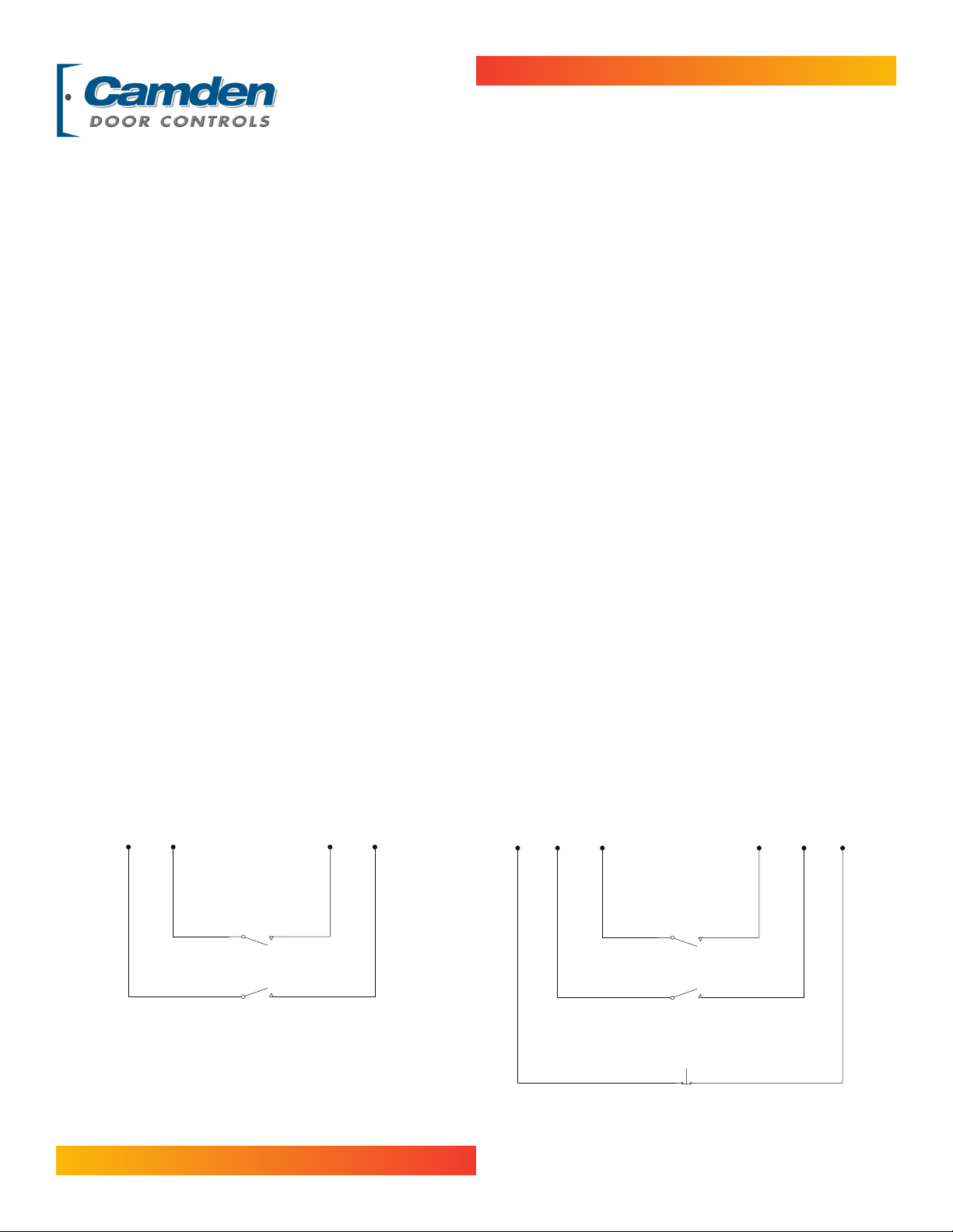
FOR EXAMPLE: On the CI-1KX & CI-1KF, the two orange
leads are tied together and connected to the operator feed.
On the CI-1KXS & CI-1KFS, (with stop button) the operator
feed goes to one black wire, through the stop button and
other black wire and joins the two orange wires, all tied
together with the common return to the operator for the
holding circuit. For both units, the yellow wire is the “OPEN”
and the blue wire is the “CLOSED”.
CI-KX & CI-KF
Orange
Orange
File: CI-KX & KF
Revised: January 14, 2008
Part No: 40-82B066
Schematic
Close
Open
Blue
Yellow
CI-KXS & CI-KFS
Schematic
Black
Orange
Orange
Close
Open
Stop
Blue
Yellow
Black
 Loading...