


1
840W Power Amp.
Issue Date: November 2008
SERVICE MANUAL – AP23914/1
Specifications:
Power Output – Stereo / Mono 200W per channel 8 Ohms
350W per channel 4 Ohms
Power Output – Bridged Mono 500W 8 Ohms
800W 4 Ohms
THD (unweighted) < 0.001% 1kHz
< 0.005% 20Hz – 20kHz
Frequency Response 5Hz – 80kHz – 1dB
S/N ration (ref 1W/8 Ohm) > 90 dB (unweighted)
Sensitivity Stereo or Mono =
(for 200W 8 Ohms) 1.5V rms unbalanced
1.5 + 1.5V rms balanced
Bridged Mono =
0.775V rms unbalanced
0.775V + 0.775V rms balanced
Input Impedances Balanced input 38 kOhm
Unbalanced input 68 kOhm
Damping factor > 125 at 1 kHz
Trigger In 5 – 12V AC or DC
Trigger Out 12V DC @ 100mA
Power consumption Maximum 2400W
Active (no signal) < 180W
Standby < 5W
Dimensions (H x W x D) 148 x 430 x 365mm
(5.8 x 16.9 x 14.4”)
Weight 19.6kg (33lbs)
Audio Partnership, Gall ery Court, Hankey Place, Lo ndo n, SE1 4BB, UK
Tel: +44 (0)20 7940 2200
Fax: +44 0 20 7940 2233

2
CAMBRIDGE AUDIO AZUR 840W POWER AMP SERVICE MANUAL
TABLE OF CONTENTS
Specifications 1
Table of Contents
Front Panel Details
Rear Panel Connections 5
Safety Instructions 6
Service Adjustment Procedure_______________________________________________7
Exploded Drawing 8
Exploded Drawing Parts List 9
Power PCB Schematic
Power PCB Schematic (Revision 1)___________________________________________ 11
Power PCB Layout
Power PCB Layout (Revision 1)______________________________________________ 13
Power Board Bill of Materials
Power Board Bill of Materials (Updated Revision)________________________________ 15
Input PCB (Mains Circuitry) Schematic
Input PCB (Mains Circuitry) Schematic (Revision 1)______________________________ 17
Input PCB (Audio Right) Schematic
Input PCB (Audio Right) Schematic (Revision 1)_________________________________ 19
Input PCB (Mircrocontroller) Schematic
Input PCB (Microcontroller) Schematic (Revision 1)______________________________ 22
Input PCB (Audio Left) Schematic
Input PCB (Audio Left) Schematic (Revision 1)__________________________________ 23
Input PCB Layout
Input PCB Layout (Revision 1)_______________________________________________ 25
2 - 3
4
10
12
14
16
18
20
22
24

3
TABLE OF CONTENTS Cont
Input PCB Board Bill of Materials
Power Amp Schematic
Power Amp Power Supplies Schematic
Power Amp PCB Layout
Power Amp Module Bill of Materials
Control Bus PCB Layout
Control Bus PCB Schematic
Control Bus Bill of Materials
Control Bus Bill of Materials (Updated Revision)_________________________________ 36
Mode Switch PCB Schematic
Mode Switch PCB Layout
Mode Switch PCB Layout (Revision 1)_________________________________________ 39
Mode Switch Bill of Materials
Mode Switch Bill of Materials (Updated Revision)_________________________ _______ 41
On/Standby Switch Schematic
On/Standby Switch PCB Layout
On/Standby Switch Bill of Materials
26 - 27
28
29
30
31 - 32
33
34
35
37
38
40
42
43
44
Cambridge Audio Azur 840W Power Amplifier
4
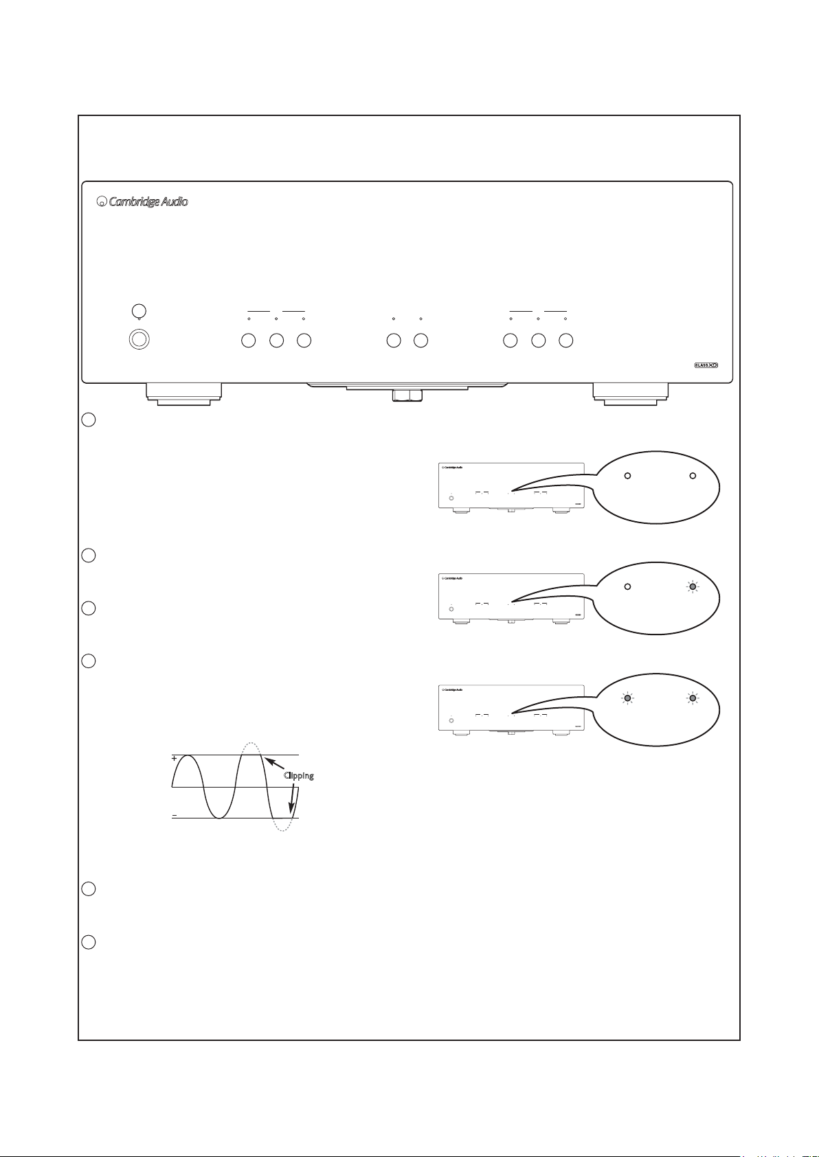
Front panel controls
azur 840W
Class XD Power Amplifier
1
Standby / On
Left Right
2 3 4 2 3 45 6
1
Standby/On
Switches the unit between Standby mode (indicated by dim power LED)
and On (indicated by bright power LED). Standby mode is a low power
mode where the power consumption is less than 10 Watts. The unit
.esu ni ton nehw edom ybdnatS ni tfel eb dluohs
When the 840W is switched out of Standby mode it will automatically
check for faults and allow the power amplifier stages to stabilise before
un-muting the speaker outputs.
Note: The protection LEDs will flash whilst this check is being done.
2
Output
Indicates that the Left or Right output is active. The LED (light-emitting
diode) is on for an active output, off for inactive (i.e. muted).
3
Protection
If this LED is constantly on the 840W has detected a fault on either the
Left or Right channel and is protecting itself.
4
Clipping
This LED indicates that the 840W has detected that either the Left or
Right channel is being overdriven or clipped.
Clipping distortion is caused at high volume levels when the output
signal attempts to go outside the maximum voltage that the connected
pre-amplifier can provide, causing the tops of the signal to flatten off.
BridgedClippingOutput
MonoProtection
LED indicators
Stereo output:
Mono output:
Bridged Mono output:
Standby / On
Standby / On
Standby / On
Left
BridgedClippingOutput
MonoProtection
Left Right
BridgedClippingOutput
MonoProtection
Left Right
BridgedClippingOutput
MonoProtection
ClippingOutput Protection
azur 840W
Class XD Power Amplifier
Right
ClippingOutput Protection
Class XD Power Amplifier
ClippingOutput Protection
Class XD Power Amplifier
ClippingOutput Protection
Bridged Mono
azur 840W
Bridged Mono
840W
azur
Bridged Mono
Clippin g
When the 840W detects clipping this LED will briefly flash. If the clipping
reaches a dangerous amount that could damage the amplifier or
attached speakers the unit will then go into protection.
5
Bridged
This LED indicates that the 840W is being used in Bridged mode. (The
Mono LED will also be illuminated.)
6
Mono
This LED indicates that the 840W is being used in a Mono mode.
Front Panel Contols
Cambridge Audio Azur 840W Power Amplifier
5
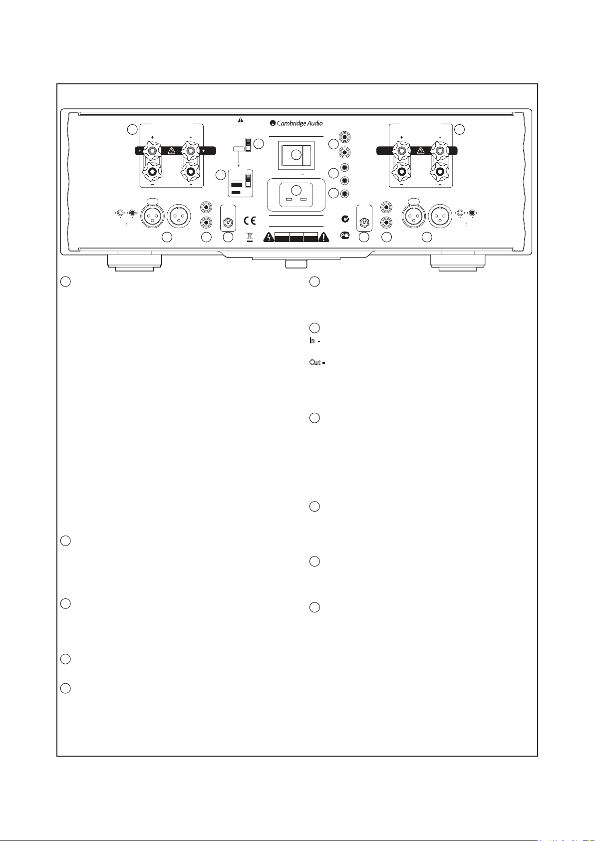
In Loop
1 = Ground
2 =
3 =
Loudspeaker Terminals - Right
Impedance 4 - 8 ohms
Please ensure that loudspeaker terminals are fully tightened
1
Veuillez s'assurer que les bornes de l'enceinte sont entièrement serrées
Balanced Audio - Right Unbalanced
Audio - Right
Loop OutputInput
Input
Loop Output
IMPORTANT!
Only change modes
when unit is off.
Refer to Manual for
more information.
Stereo
Mono
Bridged
only!
Mono Mode
6
Bi-Amp
Bridged
Bridged
Use Left Input for
Bridged / Bi-Amp
operation.
Right
Input Type
Balanced Balanced
Balanced
Unbalanced
azur 840W Class XDTM Power Amplifier
5
2 3 4
1
Loudspeaker terminals
For normal wiring, connect the wires from your left channel loudspeaker
to the LEFT + & - terminals, and the wires from the right channel
loudspeaker to the RIGHT + & - terminals. In each case, the red terminal
is the positive output and the black terminal is the negative output.
Other dual mono schemes are also possible if two 840Ws are used.
Refer to later sections of this manual for more information.
Use speakers with a nominal impedance of between 4-8 ohms. Care
should be taken to ensure no stray strands of wire short the
loudspeaker outputs together. Please ensure that the loudspeaker
terminals have been tightened completely to provide a good electrical
connection. It is also possible for the sound quality to be affected if the
screw terminals are loose.
Audio input types
The 840W features either unbalanced (phono/RCA) or balanced (XLR)
input connections. Either type may be used but not both at the same
time. The balanced connection is the higher quality option and can
reject noise and interference in the cable when used with other
equipment that supports this function. An XLR connector is wired Pin 1
- Ground; Pin 2 - Hot (in-phase); Pin 3 - Cold (phase-inverted).
Use the Left and Right Input Type switch (Item 4) to select the
connection type you wish to use. When using either the balanced or
unbalanced input, make sure that no cables or equipment are
connected to the unused input, as this may degrade operation. The
unused input does not need to be terminated and this should not be
done.
2
Balanced Audio
For connection to the balanced XLR outputs of suitable pre-amplifiers
that have this kind of output (such as our own 840E model). The preamplifier used should be capable of providing at least 1V rms of output
per phase (i.e. at both of + and – terminals of the XLR, more is also
fine). Nearly all modern pre-amplifiers fulfill this requirement.
3
Unbalanced Audio
For connection to the normal (single ended) RCA/Phono outputs of a
suitable pre-amplifier (such as our own 840E model). The pre-amplifier
used should be capable of providing at least 1V rms of output (more is
fine). Nearly all modern pre-amplifiers fulfil this requirement.
Designed in London, England
www.cambridge-audio.com
11
Power AC
10
230V AC ~ 50Hz
:
Power Rating
Max Power Consumption : 1600W
CAUTION
AVIS
ACHTUNG
Risque de choc
Vorm öffnen
Risk of electric
electrique.
des gerätes.
shock.
Ne pas ouvrir.
Netzstecker ziehen.
Do not open.
When Mono mode has been selected, switches the 840W between BiAmped Mono and Bridged Mono. Refer to later sections of this manual
for more information.
In - Allows un-modulated commands from multi-room systems or other
components to be received by the unit.
Out - Loop out for Control Bus commands to another unit.
The 840W can also be switched between On and Standby mode by
connecting the Control Bus output of an 840E pre-amplifier to the
Control Bus input of the 840W. Refer to the ‘Power syncing’ section of
this manual for more information.
For Custom Install use, the 840W can be turned on and off (i.e. brought
in and out of Standby mode) by the presence of 5-12V DC at the Trigger
input. A trigger input will also produce an internally generated 12V DC
trigger output at the Output/Thru connection. Turning the 840W on from
the front panel also produces a 12V DC trigger output at the
Output/Thru connection. This can be used to turn on/Standby other
connected power amplifiers or other equipment if desired. Refer to the
‘Power syncing’ section of this manual for more information.
Allows modulated IR commands from multi-room systems or IR repeater
systems to be received by the unit. Commands received here are not
looped out of the Control Bus. Refer to the ‘Custom installation’ section
for more information.
Once you have completed all connections to the unit, plug the AC power
cable into an appropriate mains socket then switch on. Your unit is now
ready for use.
Switches the unit on and off. If the 840W is not going to be used for long
periods of time it should be turned off using this switch.
In
Control Bus
7
ffOnO
8
9
N1863
AЯ
46
6
Mono mode switch
7
Control Bus
8
Trigger In, Out/Thru
9
IR (Infra-Red) Emitter In
10
AC power socket
11
Power On/Off
Bridged
Out
In
Trigger
Out/Thru
IR Emitter
Audio - Left
In
Left
Input Type
Unbalanced
Loop Output
4 3 2
This device complies with part 15 of the FCC Rules. Operation is subject to the following two conditions:
2) This device must accept any interference, including interference that may cause undesired operation
Veuillez s'assurer que les bornes de l'enceinte sont entièrement serrées
only!
Input
Manufactured in an ISO9001 approved facility
1) This device may not cause harmful interference
Loudspeaker Terminals - Left
Impedance 4 - 8 ohms
Please ensure that loudspeaker terminals are fully tightened
Class 2 WiringClass 2 Wiring
Balanced Audio - LeftUnbalanced
1
Loop OutputInput
In Loop
1 = Ground
2 =
3 =
Input Type switch
4
Use to select a balanced or unbalanced connection type for the input.
5
Stereo/Mono mode switch
Switches the 840W between ‘normal’ Stereo operation (where one
840W is used for a pair of speakers) and Mono operation (where two
840W’s are used one for each speaker). Refer to later sections of this
manual for more information.
Rear Panel Connections
Cambridge Audio Azur 840W Power Amplifier
6
Important safety instructions
For your own safety please read the following important safety
instructions carefully before attempting to connect this unit to the mains
power supply. They will also enable you to get the best performance and
prolong the life of the unit:
1. Read these instructions.
2. Keep these instructions.
3. Heed all warnings.
4. Follow all instructions.
5. Do not use this apparatus near water.
6. Clean only with a dry cloth.
7. Do not block any ventilation openings. Install in accordance with the
manufacturer's instructions.
8. Do not install near any heat sources such as radiators, heat registers,
stoves, or other apparatus (including amplifiers) that produce heat.
9. Do not defeat the safety purpose of the polarized or grounding-type
plug. A polarized plug has two blades with one wider than the other.
A grounding type plug has two blades and a third grounding prong.
The wide blade or the third prong are provided for your safety. If the
provided plug does not fit into your outlet, consult an electrician for
replacement of the obsolete outlet.
10. Protect the power cord from being walked on or pinched, particularly
at plugs, convenience receptacles, and the point where they exit
from the apparatus.
11. Only use attachments/accessories specified by the manufacturer.
12. Use only with the cart, stand, tripod, bracket, or table
specified by the manufacturer, or sold with the apparatus.
When a cart is used, use caution when moving the
cart/apparatus combination to avoid injury from tip-over.
13. Unplug this apparatus during lightning storms or when unused for
long periods of time.
14. Refer all servicing to qualified service personnel. Servicing is
required when the apparatus has been damaged in any way, such
as the power-supply cord or plug being damaged, liquid has been
spilled or objects have fallen into the apparatus, the apparatus has
been exposed to rain or moisture, does not operate normally, or has
been dropped.
WARNING - To reduce the risk of fire or electric shock, do not expose
this unit to rain or moisture.
The unit is of Class 1 construction and must be connected to a mains
socket outlet with a protective earthing connection.
The unit must be installed in a manner that makes disconnection of the
mains plug from the mains socket outlet (or appliance connector from the
rear of the unit) possible. Where the mains plug is used as the disconnect
device, the disconnect device shall remain readily operable. Only use the
mains cord supplied with this unit.
Please ensure there is ample ventilation (at least 10cm clearance all
round). Do not put any objects on top of this unit. Do not situate it on a
rug or other soft surface and do not obstruct any air inlets or outlet
grilles. Do not cover the ventilation grilles with items such as
newspapers, table-cloths, curtains etc.
This unit must not be used near water or exposed to dripping or
splashing water or other liquids. No objects filled with liquid, such as
vases, shall be placed on the unit.
CAUTION
Risk of electric
shock.
Do not open.
The lightning flash with the arrowhead symbol within an equilateral
triangle is intended to alert the user to the presence of un-insulated
‘dangerous voltage’ within the product’s enclosure that may be of
sufficient magnitude to constitute a risk of electric shock to persons.
The exclamation point within an equilateral triangle is intended to alert
the user to the presence of important operating and maintenance
instructions in the service literature relevant to this appliance.
AVIS
Risque de choc
electrique.
Ne pas ouvrir.
ACHTUNG
Vorm öffnen
des gerätes.
Netzstecker ziehen.
WEEE symbol
The crossed-out wheeled bin is the European Union symbol for
indicating separate collection for electrical and electronic
equipment. This product contains electrical and electronic
equipment which should be reused, recycled or recovered and
should not be disposed of with unsor ted regular waste. Please
return the unit or contact the authorised dealer from whom you
purchased this product for more information.
CE mark
This product complies with European Low Voltage
(2006/95/EC) and Electromagnetic Compatibility
to this instruction manual. For continued compliance only Cambridge
Audio accessories should be used with this product and servicing must
be referred to qualified service personnel.
(89/336/EEC) Directives when used and installed according
C-Tick mark
This product meets the Australian Communications Authority’s
Radio communications and EMC requirements.
Ross Test Stamp
This product meets Russian electronic safety approvals.
FCC regulations
NOTE: THE MANUFACTURER IS NOT RESPONSIBLE FOR ANY RADIO OR
TV INTERFERENCE CAUSED BY UNAUTHORIZED MODIFICATIONS TO
THIS EQUIPMENT. SUCH MODIFICATIONS COULD VOID THE USER
AUTHORITY TO OPERATE THE EQUIPMENT.
This equipment has been tested and found to comply with the
limits for a Class B digital device, pursuant to Part 15 of the
FCC Rules. These limits are designed to provide reasonable
protection against harmful interference in a residential installation. This
equipment generates, uses and can radiate radio frequency energy and,
if not installed and used in accordance with the instructions, may cause
harmful interference to radio communications. However, there is no
guarantee that interference will not occur in a particular installation.
If this equipment does cause harmful interference to radio or television
reception, which can be determined by turning the equipment off and
on, the user is encouraged to try to correct the interference by one or
more of the following measures:
- Re-orient or relocate the receiving antenna.
- Increase the separation between the equipment and receiver.
- Connect the equipment into an outlet on a circuit different from that to
which the receiver is connected.
- Consult the dealer or an experienced radio/TV technician for help.
Safety Instructions
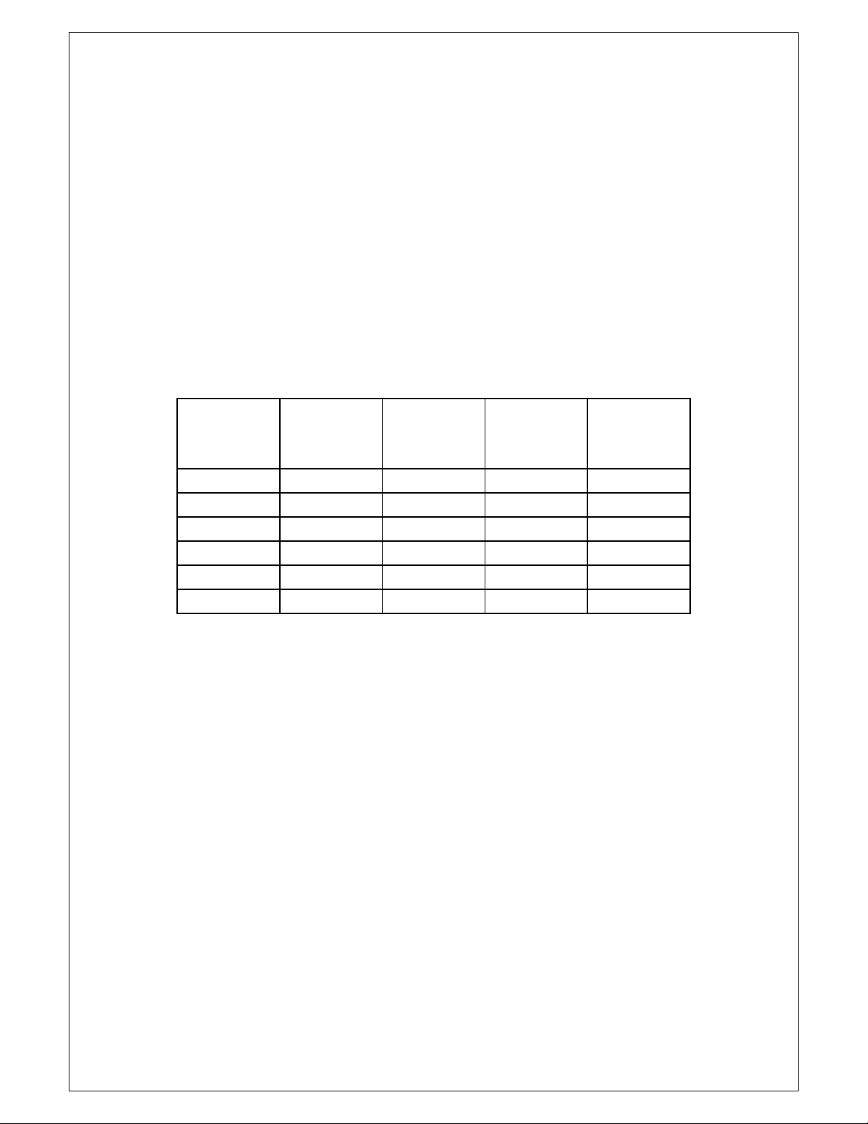
ServiceAdjustmentProcedure
7
The Bias should be 14mV when the 840W is up to temperature, this is measured
across each emitter resistor individually (R21/R22), as there is a single adjustment
for both get as close as possible. Because of the very large mass of metal in the
main heatsink, the power amplifier module
equilibrium. This table gives a guide to how the DC Bias voltage, as measured at
CN1, varies over time when the biasis setcorrectly. Thusif thebias is being set9
minutesafterturningthemoduleon,(9minutesisthe
procedure)settingthebias to 15mV will resultinthecorrectvalue of 14 mVbeing
reachedduringlong‐termoperation.
takes a long time to reach thermal
averagedurationofthistest
Timein
minutes
Temp(°C)
Main
heatsink
Temp(°C)
Driver
Heatsink1
Temp(°C)
Driver
Heatsink2
VBias
(mV+/1mV)
0 26.0 25.6 25.6 40
1 27.8 31.0 30.8 25
5 31.0 37.8 38.0 17
9 32.4 40.8 41.6 15
13 33.0 41.4 42.4 14
17 33.8 42.4 42.4 14

8
Cambridge Audio Azur 840W Power Amp
:sdaelnoisnetxeecivreS
9831YP
032E100730-1052
edeneercsmm007pmarewopotBCPtupnIelbacnoisnetx
)7NCpmarewopot)R(31NCro)L(6NCBCPtupnisknil(
0931YP
096E605401-3052
CFFyaw01deneercsmm054pmarewopotBCPtupnI
pmarewopot)R(81NCro)L(3NCBCPtupnisknil()8NC
d
9
Drawing ref AP part num ber Factorycode Description
1 PY1228 7003-008010E002 Screw M3*8 M /C 1/K TORX RE CESS ZINC-PT
1 PY1229 7003-008010E001 Screw M3*8 M/C 1/K TO RX REC ESS BLACK -PT
2 PY1378 3200-073542E000 Azur 840W 230V MAIN TRANS FOR MER TI-073520
2PY1379 3200-073542E000 840W 115V MAIN TRAN SFOR MER T I-073542
3 PY1460 3200-074050E000 Azur 840W 230V STB TRAN SFO RME R T074050
3 PY1461 3200-077810E000 840W 115V STB TRAN SFOR MER T 07781
4 PY1464 6584-150006E000-01 Azur 840W MES H SIDE PANE L BLACK PAINTED
4 PY1462 6584-150006E000-02 Azur 840W MES H SIDE PANEL SILVER PAINTED
5 PY1465 6584-150009E000-01 Azur 840W TO P PANEL BLACK PAINTED
5 PY1463 6584-150009E000-02 Azur 840W TOP PAN EL SILVER PAINTED
6 PY1466 6584-150027E000-01 Azur 840W FRO NT PANE L-B A RTW O RK (metalwork only)
6 PY1467 6584-150027E000A01 Azur840W FRON T PANEL-S ARTWOR K (m etalwork only)
PY1468 8584-035000E301 Azur 840W BLAC K FRON T PANEL ASSY REV A
PY1469 8584-035010E301 Azur 840W SILVER FRO NT PAN EL ASSY REV A
7 PY1470 9484-035000E071 Azur-840W PO W ER PC BA REV A
7 PY1520 9484-035000E072 Azur-840W POWER PCBA * Surface Mount version
8 PY1471 9484-035000E091 Azur-840W M AIN AMP PCB ASSY REV A
9 PY1472 9484-035001E091 Azur-840W SU B MAIN AMP PCB ASSY REV A
10 PY1473 9484-035000E341 Azur-840W INPU T PCBA 230V REV A
10 PY1522 9484-035001E342 * Revised Input PCBA 115 V
10 PY1523 9484-035000E342 * Revised Input PCBA 230 V
11 PY1122 6074-150004E000 Azur 840A plastic footblack
11 PY1124 6074-150004E000A01 Azur 840A plastic foot silver
PY1262 6600-070166E000 Azur 840A foot pad
12 PY1118 2331-004909E301 Speak er binding post (set)
PY1521 9484-035000E112 Azur 840W ControlBus PCBA
PY1524 9484-035001E172 Azur 840W m ode switch PC BA
Note that production after the first lot use revised PCB layout an
*
Production after 0810 are the new build
Exploded Drawing Parts List
Cambridge Audio Azur 840W Power Amplifier
10
F3
T1AL
7.5 Vrms
0 Vrms
Slow Blow Fuse
F1
T1AL
Slow Blow Fuse
C18
10nF 250V
X1/Y1 Mains Rated
F2
T1AL
Slow Blow Fuse
R3
470R
1/4W Metal Film
D2
Blue Azur LED
C17
10nF 250V
X1/Y1 Mains Rated
10nF 250V
X1/Y1 Mains Rated
J4
TERMINAL
RED
J5
TERMINAL
ORANGE
STANDBY
TRANSFORMER
J1
TERMINAL
YELLOW
17 Vrms
J3
TERMINAL
GREEN
0 Vrms
17 Vrms
J2
TERMINAL
VIOLET
R1
470R
1/4W Metal Film
D1
Blue Azur LED
OUTPUT PROTECT CLIPPING
LEFT
© COPYRIGHT
The Audio Partnership
Gallery Court
Hankey Place
LONDON SE1 4BB
Tel : +44 (0)171 940 2200
Fax : +44 (0)171 940 2233
C20
C19
10nF 250V
X1/Y1 Mains Rated
R4
470R
1/4W Metal Film
D3
Blue Azur LED
1N4004
Rectier
1N4004
Rectier
D9
D11
D13
C1
100nF 100V
Mono Ceramic
100nF 100V
Mono Ceramic
D15
1N4004
Rectier
C5
100nF 100V
Mono Ceramic
C6
100nF 100V
Mono Ceramic
1N4004
Rectier
MICROCONTROLLER SUPPLY
L7805
R9
2R2
1/2W Carbon
1
C15
100nF 50V
Mono Ceramic
U2
1
VI
U1
VI
L7815
Regulator
Regulator
C24
4700uF 25V
Electrolytic
GND
2
VO
GND
2
+9V
RELAY SUPPLY
3
VO
C21
100nF 50V
Mono Ceramic
3
C23
100nF 50V
Mono Ceramic
OPAMP SUPPLY
C13
100uF 25V
Electrolytic
C12
47uF 16V
Electrolytic
+5V
1N4004
Rectier
100nF 100V
Mono Ceramic
C4
100nF 100V
Mono Ceramic
1N4004
Rectier
D10
D14
C2
C3
D16
C27
100nF 100V
Mono Ceramic
1N4004
Rectier
4700uF 25V
Electrolytic
C16
C25
1000uF 35V
Electrolytic
D18
Rectier
1N4004
R10
4K7
1/4W Metal Film
+15V
C7
100nF 100V
Mono Ceramic
D12
1N4004
Rectier
BRIDGED MONO
C11
1000uF 35V
Electrolytic
R5
270R
1/4W Metal Film
D4
Blue Azur LED
BRIDGING SWITCH
VI
2
U3
L7915
Regulator
MODE SWITCH PCB
AP20566x
1
GND
C22
VO
3
100nF 50V
Mono Ceramic
R6
270R
1/4W Metal Film
D5
Blue Azur LED
MONO SWITCH
+5V
C14
100uF 25V
Electrolytic
Q3
BC337-25
NPN Signal
D19
Rectier
1N4004
-15V
R7
470R
1/4W Metal Film
D6
Blue Azur LED
D17
1N4004
Rectier
+-
C26
4.7uF 50V
Electrolytic
MAINS FAIL DETECT
R14
22K
1/4W Metal Film
BRIGHTNESS CONTROL
R8
470R
1/4W Metal Film
D7
Blue Azur LED
RIGHT
R11
7K5
1/4W Metal Film
R12
3K0
1/4W Metal Film
R13
430R
1/4W Metal Film
Q2
BC337-25
NPN Signal
ON/STBY LED
R2
470R
1/4W Metal Film
D8
Blue Azur LED
OUTPUTPROTECTCLIPPING
+5V
Q1
BC337-25
NPN Signal
R15
430R
1/4W Metal Film
LO = NORMAL
CN2
1
2
3
3 Way
Straight Header
MAINS FAIL
+5V
P1
BLK
LED
P2
RED
SWITCH
P3
ORG
ON/STBY PCB AP20570x
+15V
-15V
+5V
+9V
MAINS FAIL
MONO SWITCH
BRIDGING SWITCH
C8
100nF 50V
Mono Ceramic
C9
100nF 50V
Mono Ceramic
C10
100nF 50V
Mono Ceramic
EMC
D18
Blue LED
CN1
1
2
3
4
5
6
7
8
9
10
11
12
13
14
15
16
16 Way
FFC Connector
TO INPUT PCB
P4
PAD
P5
PAD
P6
PAD
FRONT PANEL FIXINGS
SW1
ON/STBY SWITCH
BC337
EBC
123
+15V
0V AUDIO
-15V
0V LOGIC
+5V
+9V
MAINS FAIL (HI = FAIL)
ON/STBY SWITCH (HI = PRESSED)
MONO SWITCH
BRIDGING SWITCH
POWER LED BRIGHT (HI = BRIGHT)
OUTPUT LEDS L & R (HI = ON)
PROTECT LED L
CLIP LED L
CLIP LED R
PROTECT LED R
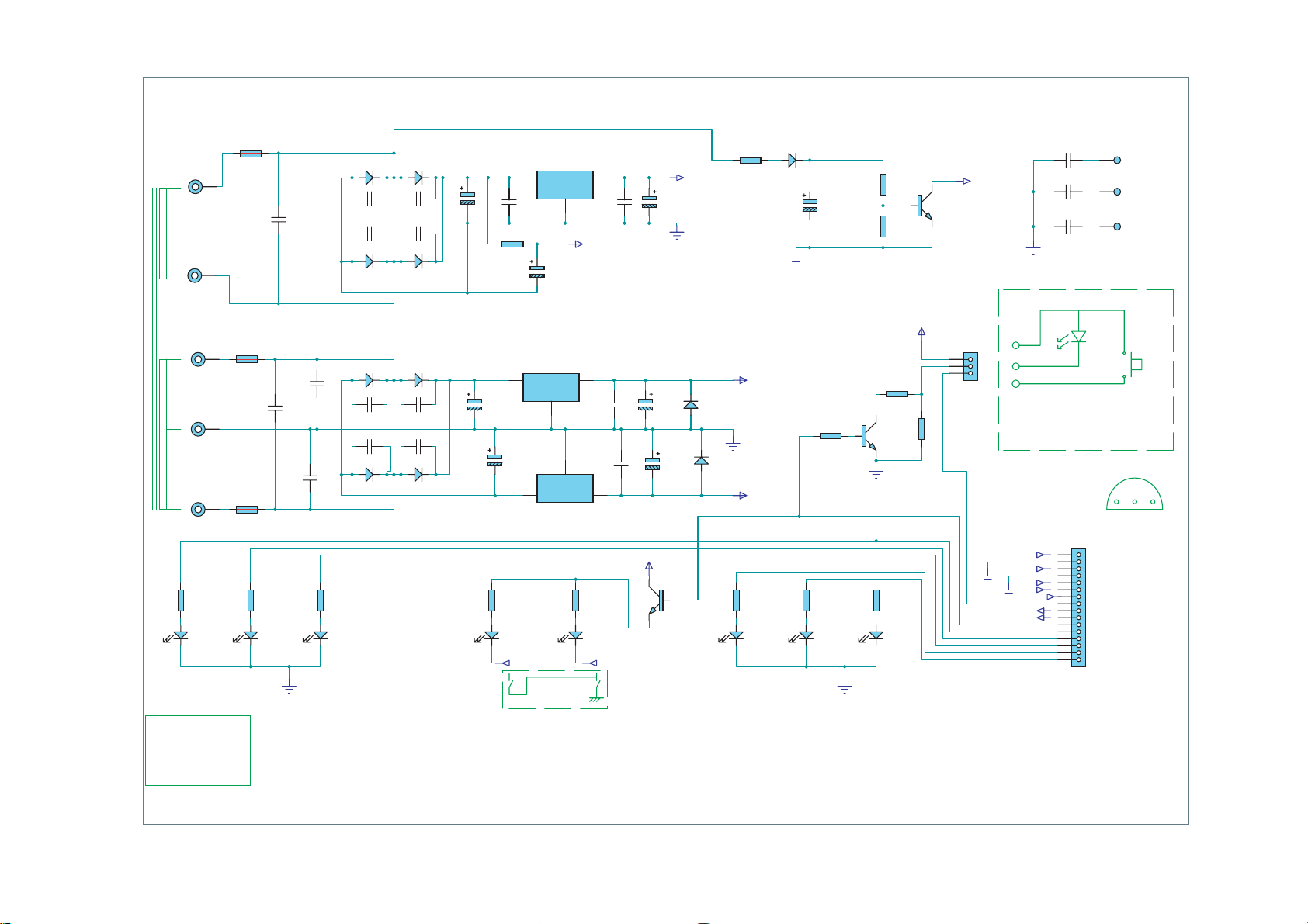
Power Circuit Board Schematic
Cambridge Audio Azur 840W Power Amplifier
11
F3
T1AL
7.5 Vrms
0Vrms
Slow Blow Fuse
F1
T1AL
Slow Blow Fuse
J4
TERMINAL
RED
J5
TERMINAL
ORANGE
STANDBY
TRANSFORMER
J1
TERMINAL
YELLOW
17 Vrms
J3
TERMINAL
GREEN
0Vrms
17 Vrms
J2
F2
T1AL
TERMINAL
SlowBlowFuse
VIOLET
R1
1206 Thick Film
470R
D1
Blu
eAzurLED
R3
1206 Thick Film
470R
D2
Blue Azur LED
OUTPUT PROTECT CLIPPING
LEFT
© COPYRIGHT
The Audio Partnership
Gallery Court
Hank
ey Place
LONDON SE14BB
Tel : +44 (0)171 940 2200
Fax : +44 (0)171 940 2233
C17
100nF 250V
Met Polyester
C18
100nF 250V
Met Polyester
R4
1206 ThickFilm
470R
D3
Blue Azur LED
D13
C1
S1D
Met. Polyester
39nF 250V
C4
Met. Polyester
D15
39nF 250V
S1D
D9
MBR1100RLG
C5
Met. Polyester
39nF 250V
C6
Met. Polyester
D11
39nF 250V
MBR1100RLG
MICROCONTROLLER SUPPLY
4700uF 25V
D14
Electrolytic
C2
S1D
Met. Polyester
39nF 250V
C3
Met. Polyester
D16
39nF 250V
S1D
D10
MBR1100RLG
C27
Met. Polyester
39nF 250V
C7
Met. Polyester
D12
39nF 250V
MBR1100RLG
C16
C15
100nF 50V
1206 Ceramic
R9
2R2
1/2W Carbon
U2
1
C25
2200uF 35V
Electrolytic
C11
2200uF35V
Electrolytic
R5
1206 Thick Film
BRIDGED MONO
270R
D4
Blue Azur LED
U1
1
VI
C24
4700uF25V
Electrolytic
L7815
Regulator
VI
2
VI
2
U3
L7915
Regulator
MODE SWITCH PCB
AP20566x
L7805
Regulator
GND
GND
2
1
GND
3
VO
+9V
RELAY SUPPLY
OPAMP SUPPLY
3
VO
C21
Met. Polyester
47nF 63V
C22
Met. Polyester
47nF 63V
VO
3
R6
1206 Thick Film
270R
D5
Blue AzurLED
MONO SWITCHBRIDGING SWITCH
C23
100nF 50V
1206 Ceramic
C13
100uF 25V
Electrolytic
C14
100uF 25V
Electrolytic
+5V
Q3
BC846
NPN SmallSignal
C12
10uF 16V
EL Capacitor SMT
DGND
FB1
On 24AWG Wire
1uH Ferrite
AGND
+5V
D18
S1D
D19
S1D
DGND
R10
1206 Thick Film
4K7
+15V
AGND
-15V
R7
1206 Thick Film
470R
D6
Blue Azur LED
D17
S1D
C26
4.7uF 50V
EL Capacitor SMT
DGND
MAINS FAIL DETECT
R14
1206 Thick Film
22K
DGND
BRIGHTNESS CONTROL
R8
1206 ThickFilm
470R
D7
Blue Azur LED
RIGHT
DGND
R11
1206 Thick Film
7K5
R12
1206 Thick Film
3K0
R13
1206 Thick Film
430R
Q2
BC846
NPN SmallSignal
ON/STBY LED
R2
hick Film
1206 T
470R
D8
Blue Azur LED
OUTPUTPROTECTCLIPPING
+5V
Q1
BC846
NPN SmallSignal
R15
1206 Thick Film
430R
LO = NORMAL
CN2
1
2
3
3Way
Straight Header
MAINS FAIL
DGND
+5V
P1
BLK
P2
RED
SWITCH
P3
ORG
ON/STBY PCB AP20570x
+15V
-15V
+5V
AGND
+9V
DGND
MAINS FAIL
MONO SWITCH
BRIDGING SWITCH
C8
100nF 50V
1206 Ceramic
C9
100nF 50V
1206 Ceramic
C10
100nF 50V
1206 Ceramic
Blue LED
LED
CN1
1
2
3
4
5
6
7
8
9
10
11
12
13
14
15
16
16 Way
FFC Connector
TO INPUT PCB
P4
PAD
C19
10nF 50V
X7R Ceramic
P5
0805
PAD
C20
10nF 50V
X7R Ceramic
P6
0805
PAD
C28
10nF 50V
X7R Ceramic
0805
D18
SW1
ON/STBY SWITCH
BC337
EBC
+15V
0V AUDIO
-15V
0V LOGIC
+5V
+9V
MAINS FAIL (HI = FAIL)
ON/STBY SWITCH (HI = PRESSED)
MONO SWITCH
BRIDGING SWITCH
POWER LED BRIGHT (HI = BRIGHT)
OUTPUT LEDS L&R (HI=ON)
PROTECT LED L
CLIP LED L
CLIP LED R
PROTECT LED R
123
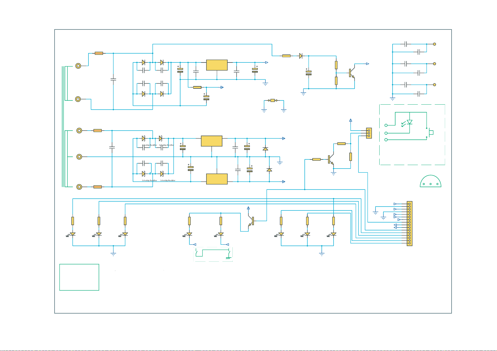
Power Circuit Board Schematic (Revision 1)
Cambridge Audio Azur 840W Power Amp
12
??
??
??
??
??
??
??
??
??
??
??
??
???
???
???
??
??
??
??
?
???
???
??
??
??
???
??
???
???
???
??
???
???
???
???
?? ??
??
???
???
??
??
??
??
?
??
??
???
???
???
? ??
???
??
??
???
???
??
???
??
??
???
???
???
??
???? ?
???
??????
???
???
??
???
??
?
Power PCB Layout
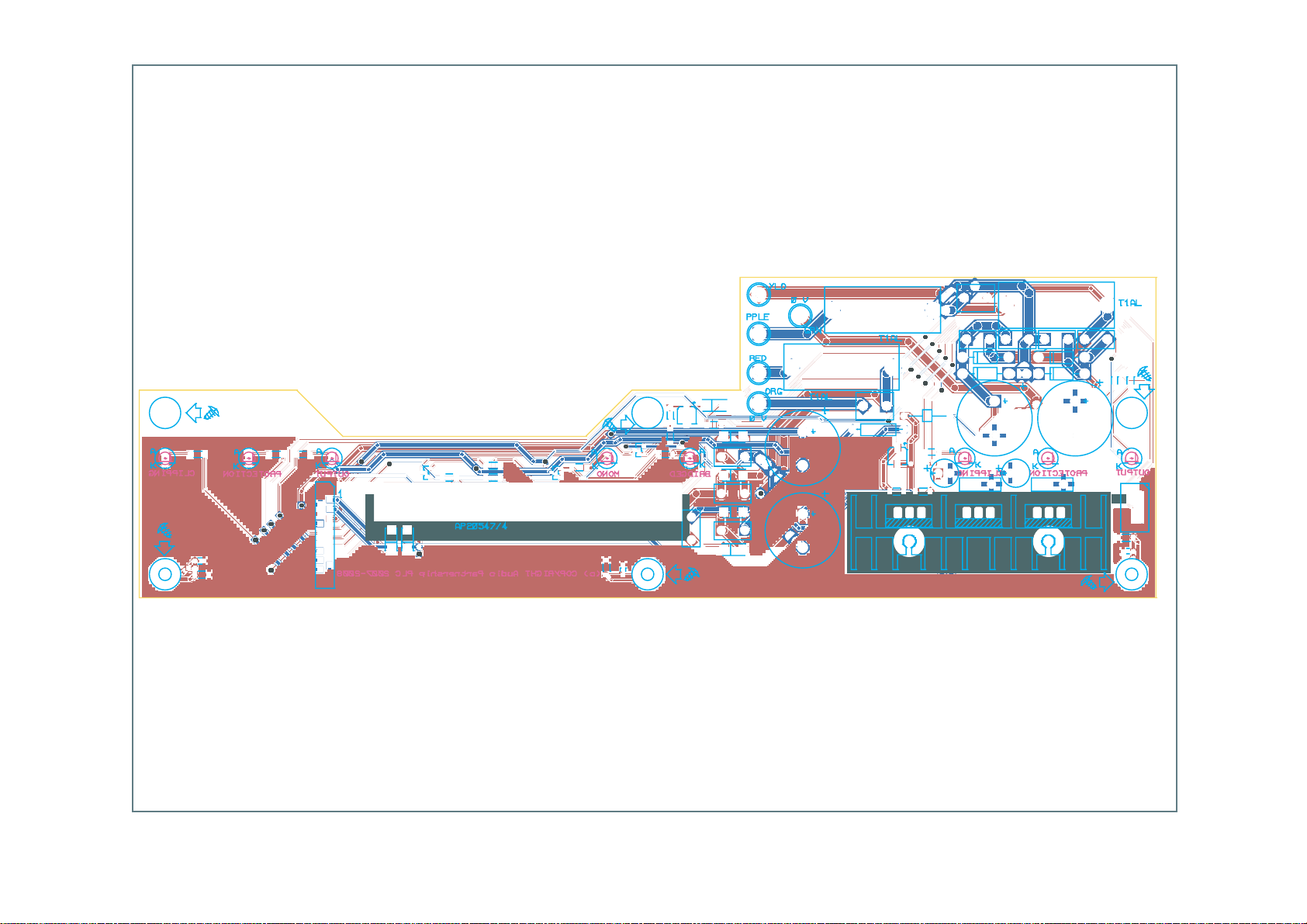
Cambridge Audio Azur 840W Power Amplifier
13
J1
J2
J3
J4
D17
C26
R11
D6
R7
C19
P4
C8
D7D8
R2
R8
CN1
Q2
D19
D18
R15
R13
R14
R6
Q3
Q1
D5
C9
C20
R10
R12
R5
C3
P5 P6
D13
C1
D14
C2
D15
C4
D16
F3
J5
C16
C24
F2
C17
FB1
R9
C12
C13
C23
C15
U1
C18
C27
C7
C6
D10
C25
3D2D D4
R4
C14
C21
U2
C22
U3
F1
C5
D9
D11D12
R3
R1
C11
D1
CN2
C10
C28
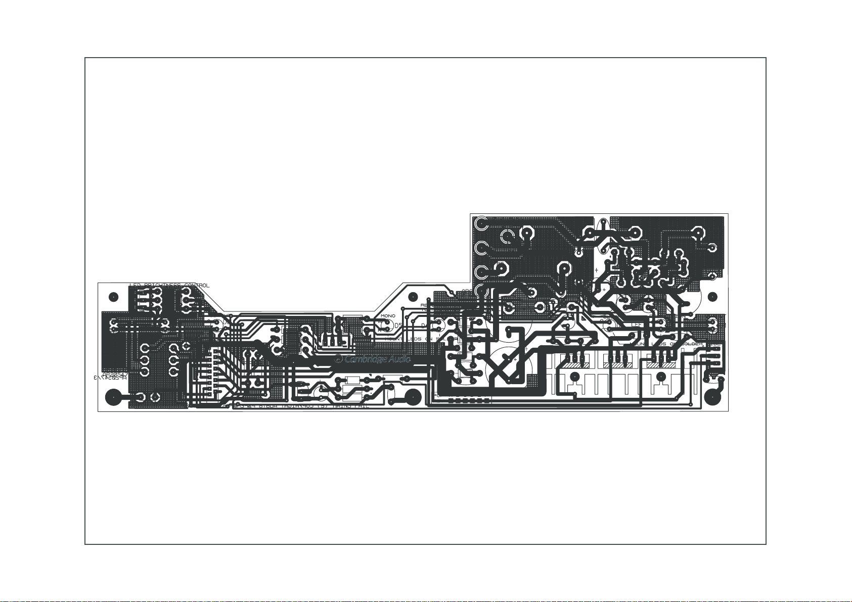
Power Circuit Board PCB Layout (Revision 1)
Cambridge Audio Azur 840W Power PCB (AP20549/4)
23
Fuse Holder Cover
3
F1-F3
PTF78 (or equivalent)
20mm Pitch
4034-780000E000
14
RESISTORS
/12R21
mliFlateMW4/1R0744
lateMW4/15K77
CAPACITORS
C-8C7cimareConoMV05Fn00111
1C1citylortcelEV61Fu7431
1C2citylortcelEV53Fu000151
CONNECTORS
DIODES
eifitceRA1V00402
FUSES
21 T1AL Slow Blow Fuse 3 F1-F3 20mm
-
INTEGRATED CIRCUITS
TRANSISTORS
-
SETONN/PyrotcaFofnIegakcaPecnareloTNPnaMtnedItnenopmoCytQepyT/noitpircseDeulaV
hctiPmm21%019R1nobraCW2
hctiPmm01%16R,5R2mliFlateMW4/1R0722
hctiPmm01%151R,31R2mliFlateMW4/1R0343
hctiPmm01%18R,7R,4R-1R6
hctiPmm01%121R1mliFlateMW4/10K35
hctiPmm01%101R1mliFlateMW4/17K46
hctiPmm01%111R1mliF
hctiPmm01%141R1mliFlateMW4/1K228
100-490301-0111%0202C-71C4detaRsniaM1Y/1XV052Fn019
0401-6011hctiPmm5%0172C,7C-1C8cimareConoMV001Fn001V001Fn00101
100-46
000-340401-0011hctiPmm5%0132C-12C,51C,01
000-410074-2011aiDmm5%022
000-420101-2011aiDmm6%0241C,31C2citylortcelEV52Fu00141
000-430201-2011%0252C,1
100-420274-2011aiDmm61%0242C,61C2citylortcelEV52Fu007461
hguorhT61-VSS-001D1NC1rotcennoCCFFyaW6171
000E000087-1304hctiPmm02)tnelaviuqero(87FTP3F-1F3esaBredloHesuF22
22OT5197L3U1rotalugeRV51-62
100E105610-1032eloH
400-001300-0032hctiPmm5.2A-HX-B3B2NC1redaeHthgiartSyaW381
000-040041-104114OD4004N191D-9D11r
007E433050-8714022OT5087L1U1rotalugeRV5+42
006E203051-8714022OT5187L2U1rotalugeRV51+52
006E203051-97140
001-000733-003129OT52-733CB3Q-1Q3langiSNPNAm003V5472
aiDmm5000-440774-2011%0262C1citylortcelEV05Fu7.421
BCP
otesabDELgnicapsmm8300-030000-0013031-M369BFH8D-1D8mm3DELruzAeulB91
Note: resistors, capacitors and other 'generic' components are
Note: resistors, capacitors and other 'generic' components are
not usually stocked by the manufacturer. Please obtain these locally.
not usually stocked by the manufacturer. Please obtain these locally.
 Loading...