

Cambridge Audio Azur 540-R Mk2 Owners manual

azur 540R V2.0
AV receiver
User’s manual

2 Azur AV receiver
Introduction .................................................................................................3
Limited warranty ........................................................................................4
Safety precautions .....................................................................................5
Important safety instructions ....................................................................6
Front panel connections ............................................................................8
Rear panel connections ...........................................................................10
Remote control ........................................................................................12
Surround Sound modes ...........................................................................14
Loudspeaker positioning .........................................................................15
Loudspeaker connections .......................................................................16
Audio connections ...................................................................................17
Video connections ....................................................................................17
Digital connections ..................................................................................18
6.1 Direct In .. ...........................................................................................18
6.1 Preamp Out .......................................................................................19
Front Input connections ...........................................................................19
Aerial connections ....................................................................................20
On-screen display (OSD) ..........................................................................20
OSD menus ...............................................................................................21
Surround Sound setup .............................................................................22
Operating instructions..............................................................................26
Custom installation use ...........................................................................28
Reset/Back-up memory ...........................................................................28
Troubleshooting .......................................................................................29
Technical Specifications ..........................................................................30
CONTENTS

In addition, the 540R V2.0 also carries a 6.1 channel analogue input.
This feature allows for the connection of a DVD Audio or SACD player
equipped with a 5.1/6.1 output. This means that the 540R V2.0 is fully
equipped to make the most of these exciting new music formats.
As well as the full complement of audio inputs, the 540R V2.0 also
performs Composite, S-Video and Component Video switching. This
means that the 540R V2.0 can be used as a hub to route video signals
in addition to the audio ones.
All this proprietary engineering is housed within our low resonance,
acoustically damped chassis. An Azur Navigator remote control is also
provided, giving full remote control of your AV receiver in an attractive
and easy to use handset.
Your 540R V2.0 can only be as good as the system it is connected to.
Please do not compromise on your speakers or cabling. Naturally we
particularly recommend DVD/CD players or other source equipment
from the Cambridge Audio Azur range, which have been designed to the
same exacting standards as our receivers. Your dealer can also supply
excellent quality Cambridge Audio interconnects to ensure your system
realises its full potential.
Thanks for taking the time to read this manual, we do recommend you
keep it for future reference.
Matthew Bramble
Technical Director
540R V2.0 AV receiver
Azur AV receiver 3
Thank you for purchasing this Cambridge Audio Azur range AV receiver.
This 540R version 2 is part of our commitment to the on-going
development of the Azur range. We hope that you will appreciate the
results and enjoy many years of listening pleasure from it.
About the 540R V2.0
The 540R V2.0 is designed to maximise multi-channel performance
without compromising on stereo reproduction. As such, the six 80W
discrete amplifiers are kept as separate as possible from the processing
and input stages. An oversized power supply ensures that the 540R
V2.0 can maintain a high power output into even difficult speaker loads
to ensure a powerful and effortless sound.
For this V2.0 model we have fitted an improved volume control IC, larger
PSU capacitors and made various improvements to the circuitry further
elevating the sound quality of the unit. The Video switching has also
been completely re-designed to give higher bandwidth compatible with
HDTV and the unit now features full On Screen Display.
A full range of digital and analog inputs are fitted to the 540R V2.0.
Digital inputs allow for the connection of suitably equipped DVD players,
satellite boxes and games consoles for decoding into stereo or digital
surround formats. Conventional analog stereo inputs allow the
connection of CD players and the like to ensure the best possible stereo
reproduction. The 540R V2.0 is also capable of decoding analog stereo
sources in Dolby Pro Logic
®
II and DTS Neo:6, for a convincing and
effective surround experience from an analog source. This ensures
sources such as analog televisions and VCRs can also make full use of
the 540R V2.0's surround capabilities.
INTRODUCTION

4 Azur AV receiver
Cambridge Audio warrants this product to be free from defects in
materials and workmanship (subject to the terms set forth below).
Cambridge Audio will repair or replace (at Cambridge Audio's option) this
product or any defective parts in this product. Warranty periods may vary
from country to country. If in doubt consult your dealer and ensure that
you retain proof of purchase.
To obtain warranty service, please contact the Cambridge Audio
authorised dealer from which you purchased this product. If your dealer
is not equipped to perform the repair of your Cambridge Audio product,
it can be returned by your dealer to Cambridge Audio or an authorised
Cambridge Audio service agent. You will need to ship this product in
either its original packaging or packaging affording an equal degree of
protection.
Proof of purchase in the form of a bill of sale or receipted invoice, which
is evidence that this product is within the warranty period, must be
presented to obtain warranty service.
This Warranty is invalid if (a) the factory-applied serial number has been
altered or removed from this product or (b) this product was not
purchased from a Cambridge Audio authorised dealer. You may call
Cambridge Audio or your local country Cambridge Audio distributor to
confirm that you have an unaltered serial number and/or you purchased
from a Cambridge Audio authorised dealer.
This Warranty does not cover cosmetic damage or damage due to acts
of God, accident, misuse, abuse, negligence, commercial use, or
modification of, or to any part of, the product. This Warranty does not
cover damage due to improper operation, maintenance or installation,
or attempted repair by anyone other than Cambridge Audio or a
Cambridge Audio dealer, or authorised service agent which is authorised
to do Cambridge Audio warranty work. Any unauthorised repairs will void
this Warranty. This Warranty does not cover products sold AS IS or WITH
ALL FAULTS.
REPAIRS OR REPLACEMENTS AS PROVIDED UNDER THIS WARRANTY
ARE THE EXCLUSIVE REMEDY OF THE CONSUMER. CAMBRIDGE AUDIO
SHALL NOT BE LIABLE FOR ANY INCIDENTAL OR CONSEQUENTIAL
DAMAGES FOR BREACH OF ANY EXPRESS OR IMPLIED WARRANTY IN
THIS PRODUCT. EXCEPT TO THE EXTENT PROHIBITED BY LAW, THIS
WARRANTY IS EXCLUSIVE AND IN LIEU OF ALL OTHER EXPRESS AND
IMPLIED WARRANTIES WHATSOEVER INCLUDING, BUT NOT LIMITED TO,
THE WARRANTY OF MERCHANTABILITY AND FITNESS FOR A PRACTICAL
PURPOSE.
Some countries and US states do not allow the exclusion or limitation of
incidental or consequential damages or implied warranties so the above
exclusions may not apply to you. This Warranty gives you specific legal
rights, and you may have other statutory rights, which vary from state to
state or country to country.
LIMITED WARRANTY
540R V2.0 AV receiver
Azur AV receiver 5
Checking the Power Supply Rating
For your own safety please read the following instructions carefully before attempting
to connect this unit to the mains.
Check that the rear of your unit indicates the correct supply voltage. If your mains
supply voltage is different, consult your dealer.
This unit is designed to operate only on the supply voltage and type that is
indicated on the rear panel of the unit. Connecting to other power sources may
damage the unit.
This equipment must be switched off when not in use and must not be used unless
correctly earthed. To reduce the risk of electric shock, do not remove the unit's
cover (or back). There are no user serviceable parts inside. Refer servicing to
qualified service personnel. If the power cord is fitted with a moulded mains plug
the unit must not be used if the plastic fuse carrier is not in place. Should you lose
the fuse carrier the correct part must be reordered from your Cambridge Audio
dealer.
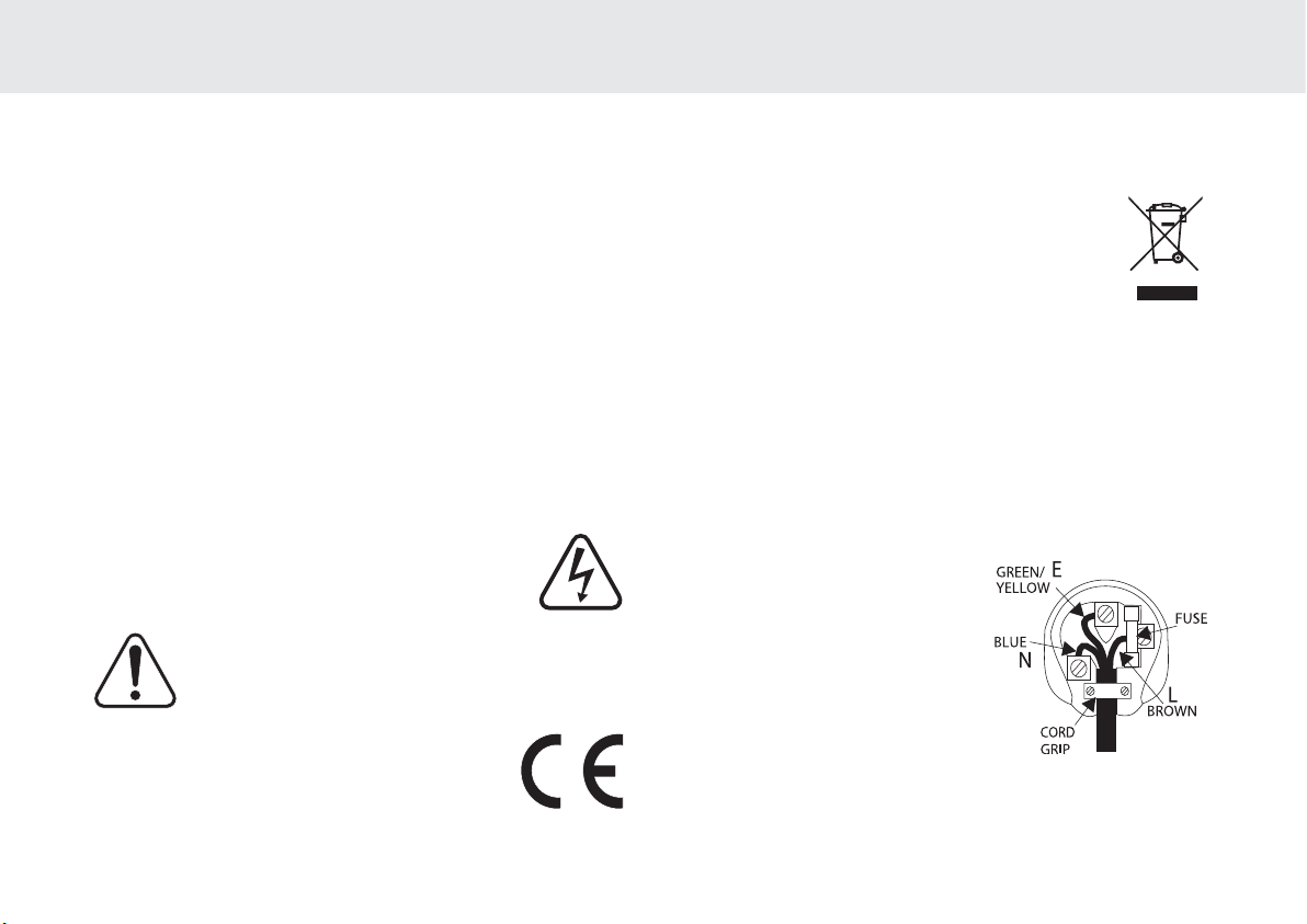
The lightning flash with the arrowhead symbol within an equilateral
triangle is intended to alert the user to the presence of un-insulated
‘dangerous voltage’ within the product’s enclosure that may be of
sufficient magnitude to constitute a risk of electric shock to
persons.
The exclamation point within an equilateral triangle is intended to
alert the user to the presence of important operating and
maintenance instructions in the service literature relevant to this
appliance.
This product complies with European Low Voltage (73/23/ EEC)
and Electromagnetic Compatibility (89/336 /EEC) Directives
when used and installed according to this instruction manual. For
continued compliance only Cambridge Audio accessories should
be used with this product and servicing must be referred to
qualified service personnel.
The crossed-out wheeled bin is the European Union symbol for
indicating separate collection for electrical and electronic
equipment. This product contains electrical and electronic
equipment which should be reused, recycled or recovered and
should not be disposed of with unsorted regular waste. Please
return the unit or contact the authorised dealer from whom you
purchased this product for more information.
Plug Fitting Instructions (UK Only)
The cord supplied with this appliance is factory fitted with a UK mains plug fitted
with a 5 amp fuse inside. If it is necessary to change the fuse, it is important that
a 5 amp one is used. If the plug needs to be changed because it is not suitable for
your socket, or becomes damaged, it should be cut off and an appropriate plug
fitted following the wiring instructions below. The plug must then be disposed of
safely, as insertion into a mains socket is likely to cause an electrical hazard.
Should it be necessary to fit a 3-pin BS mains plug to the power cord the wires
should be fitted as shown in this diagram. The colours of the wires in the mains
lead of this appliance may not correspond with the coloured markings identifying
the terminals in your plug. Connect them as follows:
The wire which is coloured BLUE must be
connected to the terminal which is marked
with the letter ‘N’ or coloured BLACK.
The wire which is coloured BROWN must be
connected to the terminal which is marked
with the letter ‘L’ or coloured RED.
The wire which is coloured GREEN/YELLOW
must be connected to the terminal which is
marked with the letter ‘E’ or coloured GREEN.
If your model does not have an earth wire, then disregard this instruction.
If a standard 13amp (BS 1363) plug is used, a 5 amp fuse must be fitted, or if any
other type of plug is used a 5 amp fuse must be fitted, either in the plug or adaptor,
or on the distribution board.
SAFETY PRECAUTIONS

6 Azur AV receiver
Please take a moment to read these notes before installing your 540R
V2.0, as they will enable you to get the best performance and prolong
the life of the unit. Please retain these instructions for future reference.
Ventilation
IMPORTANT - The unit will become hot when in use. Please ensure that
there is ample ventilation around the unit. Leave at least 10cm of space
between the top, back and sides. Do not situate it on a rug or other soft
surface and do not obstruct the air inlet and outlet grilles on the
underside and top cover. Do not place in an enclosed area such as a
bookcase or in a cabinet.
Positioning
Choose the installation location carefully. Avoid placing it in direct
sunlight or close to a source of heat. Also avoid locations subject to
vibration and excessive dust, cold or moisture. Do not place the unit on
an unstable surface or shelf. The unit may fall, causing serious injury to
a child or adult as well as serious damage to the product. Do not place
a CD player or other equipment on top of the unit.
This unit must not be exposed to dripping or splashing water or other
liquids. No objects filled with liquid, such as vases, shall be placed on
the unit. In the event, switch off immediately, disconnect from the mains
supply and contact your dealer for advice.
Ensure that small objects do not fall through any ventilation grille. If this
happens, switch off immediately, disconnect from the mains supply and
contact your dealer for advice.
Electronic audio components have a running in period of around a week
(if used several hours per day). This will allow the new components to
settle down, the sonic properties will improve over this time.
Grounding and polarisation
The unit may be equipped with a polarised alternating current line plug
(a plug having one blade wider than the other). This plug will fit into the
power outlet only one way. This is a safety feature. If you are unable to
insert the plug fully into the outlet, try reversing the plug. If the plug
should still fail to fit, contact your electrician to replace your obsolete
outlet. Do not defeat the safety purpose of the polarised plug. (North
America Only)
Power sources
The unit should be operated only from the type of power source
indicated on the marking label. If you are not sure of the type of powersupply to your home, consult your product dealer or local Power
Company.
This unit has been designed to be left in Standby mode when not in use,
this will increase the life of the amplifier (this is true with all electronic
equipment). If you do not intend to use this unit for a long period of time,
unplug it from the mains socket.
Power cord protection
Your power supply cord should be placed so that the power lead is not
likely to be walked on or pinched by items placed upon or against them,
paying particular attention to cords at wall plugs and where the power
lead exits from the unit.
Be sure to insert each power cord securely. To prevent hum and noise,
do not bundle the interconnect leads with the power cord or speaker
leads.
IMPORTANT SAFETY INSTRUCTIONS

540R V2.0 AV receiver
Azur AV receiver 7
Overloading
Do not overload wall outlets or extension cord as this can result in a risk
of fire or electric shock. Overloaded AC outlets, extension cords, frayed
power cords, damaged or cracked wire insulation, and broken plugs are
dangerous. They may result in a shock or fire hazard.
Lightning
For added protection during a thunderstorm, or when it is left
unattended and unused for long period of time, unplug the unit from the
wall outlet and disconnect the antenna or cable system. This will prevent
damage to the unit from lightning and power-line surges.
Outdoor antenna grounding
If an outside antenna or cable system is connected to the product, be
sure the antenna or cable system is grounded so as to provide some
protection against voltage surges and built-up static charges. Section
810 of the National Electrical Code, ANSI/NIPA No. 70-1984 (section 54
of Canadian Electrical Code, Part 1) provides information with respect to
proper grounding of the mast and supporting structure, grounding of the
lead-in wire to an antenna-discharge unit, size of grounding conductors,
location of antenna-discharge unit, connection to grounding electrodes,
and requirements for the grounding electrode.
Cleaning
Unplug the unit from the wall outlet before cleaning. To clean, wipe its
case with a moist, lint-free cloth. Do not use any cleaning fluids
containing alcohol, ammonia or abrasives. Do not spray an aerosol at or
near the unit.
Attachments
Do not use attachments not recommended by your dealer as they may
cause harm to the unit.
Servicing
These units are not user serviceable, never attempt to repair,
disassemble or reconstruct the unit if there seems to be a problem. A
serious electric shock could result if this precautionary measure is
ignored. In the event of a problem or failure, please contact your dealer.
Contact the service department should any of these conditions occur:
- When the power-supply cord or plug is damaged.
- If liquid has been spilled, or objects have fallen into the amp.
- If the unit has been exposed to rain or water.
- If the unit does not operate normally after following the operation
instructions, adjust only those controls that are covered by the
operation instructions.
- If the unit has been dropped or damaged in any way.
- When the unit exhibits a distinct negative change in performance.
IMPORTANT
If the unit is run at a very high level, a sensor will detect a temperature
rise and show "PROTECTION OVERLOAD" on the display. The unit will
then go into Standby mode. It cannot be switched on again until the
temperature has fallen to a more normal level.
8 Azur AV receiver
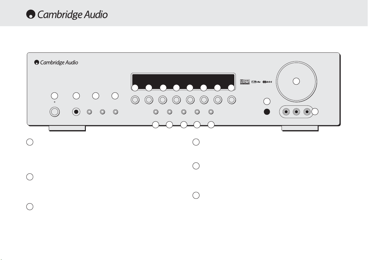
Standby/On
Switches the unit between Standby mode (indicated by dim power LED)
and On (indicated by bright power LED). Standby is a low power mode
where the power consumption is less than 10 Watts. The unit should be
left in Standby mode when not in use.
Phones
Allows for the connection of stereo headphones with a ¼" Jack plug.
Headphones with an impedance of between 32 and 600 ohms are
recommended.
Tuning +/-
Used to tune FM frequencies and skip presets in Tuner mode.
Mode/Store
Press to cycle between Tuner modes (refer to the ‘Operating
Instructions’ of this manual for more information).
Stereo
Press to listen to a source in either analog stereo or digital (LPCM)
stereo (depending on the input mode) from the front left and right
loudspeakers only.
Dolby Digital EX / DTS ES
Press to select between various standard Dolby Digital or DTS surround
5.1 modes (with suitably encoded digital source material). Also selects
extended Dolby Digital EX and DTS ES modes which provide 6.1 output
with suitably encoded EX/ES material. These modes can only be
decoded from digital audio sources (via Coaxial or Optical inputs). An
Autodetect mode is also available which allows the 540R V2.0 to
automatically set itself to the appropriate mode for digital material.
Volume
Phones Tuning Mode/Store
DVD Video 1
Dolby Digital EX/
DTS ES
DSP
Mode
Pro Logic II/
Neo 6
Input
Mode
Video 3 inputs
Video Left Right
Stereo
Video 2 Video 3 Tuner FM/AM Tape/MD/CDR CD/Aux 6.1 Direct
–+
Standby / On
azur 540R
AV Receiver
FRONT PANEL CONTROLS
1
2
3
5
1 2 3 4
5 6 7 8 9
10 11 12 13 14 15 16 17
18
19
20
4
6

540R V2.0 AV receiver
Azur AV receiver 9
Pro Logic II / Neo:6
Press to decode suitable encoded analog stereo source material into
surround sound. Autodetection for these modes is not possible and they
must be manually selected.
DSP Mode
The 540R V2.0 can create a surround sound effect even from nonencoded material by Digital Signal Processing (DSP). Press this button to
choose one of the following surround sound effects: THEATER, HALL,
MOVIE, MUSIC or ROOM.
Input Mode
Press this button to toggle between analog or optical/coaxial digital
input types for the currently selected source. The 540R V2.0 remembers
the input type selected for each source when you return to that source.
DVD
Press to select the DVD source equipment for output through the 540R
V2.0.
Video 1
Press to select the source equipment connected to Video 1 for output
through the 540R V2.0.
Video 2
Press to select the source equipment connected to Video 2 for output
through the 540R V2.0.
Video 3
Press to select the source equipment connected to Video 3 (on the front
panel) for output through the 540R V2.0.
Tuner FM/AM
Press to select the tuner for output through the 540R V2.0. In Tuner
mode also use this button to switch between FM and AM modes.
Tape/MD/CDR
Press to select the recording device connected to the Tape/MD/CDR
input for output through the 540R V2.0.
CD/Aux
Press to select the CD or other source equipment connected to CD/Aux
on the rear panel for output through the 540R V2.0.
6.1 Direct
Press to select a 5.1 or 6.1 DVD-A or SACD player connected to the 6.1
Direct In sockets.
Infrared sensor
Receives IR commands from the supplied Azur remote control. A clear
unobstructed line of sight between the remote control and the sensor is
required.
Volume
Use to increase/decrease the level of the sound from the outputs of the
540R V2.0.
Video 3 input sockets
Allows a video camera recorder/video games console to be connected
and selected by the Video 3 source button.
7
8
10
9
11
15
16
17
18
19
12
13
14
20
10 Azur AV receiver
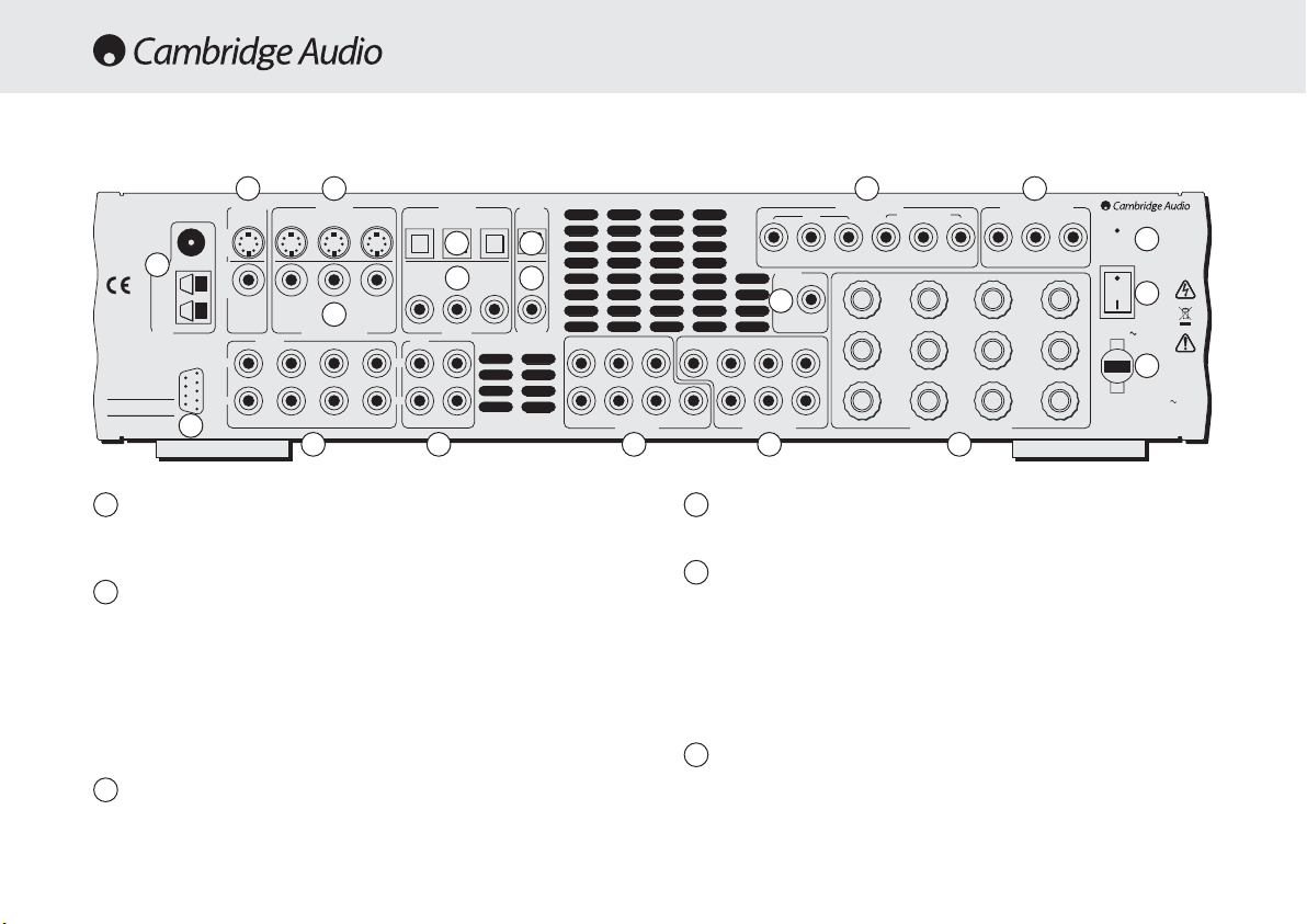
FM/AM antenna
All tuner antenna connections are made here. Refer to the ‘Antenna
Connections’ section of this manual for more information.
TV/Mon outputs
S-Video - Connect to your television via S-Video cable to display the
picture of any S-Video connected unit.
Composite - Connect to your television via RCA phono cable to display
the picture of any composite video connected unit.
These outputs are also used to view the 540R V2.0’s on-screen setup
menu.
S-Video inputs
Connect the S-Video outputs from the source equipment.
Composite Video inputs
Connect the Composite Video outputs from the source equipment.
Component Video inputs
Connect the Component Video outputs from the source equipment.
Note: The preferred connection method for video sources is always
Component Video (highest quality) then S-Video then Composite Video.
DVD Component Video sources often also support Progressive Scan
which gives better picture quality if supported by both your DVD player
and TV.
Component Video Out
Connect to the Cr/Pr, Cb/Pb, & Y terminals of a television set.
Note: There is no on-screen setup menu present on the Component
Video outputs.
REAR PANEL CONNECTIONS
1
1
2 3
4
7
9
8
10
11
5 6
12
13
14
151617
1819
20
2
3
4
5
6
FM 75Ω
TV/Mon Out
S-VideoComposite
L
R
RS232C
CD/Aux
S-Video In
Video 2 Video 1 DVD CD Video 1/Video 2 D VD
Video 2 Video 1 DVD
Composite Video In
Audio In
Video 2 Video 1 DVD
Optical In
CD DVD
Video 1/Video 2
Coax InCoax In Coax Out
Tape
L
R
Tape Play Tap e Rec
Optical
Out
RR
azur 540R V2.0
AV Receiver
Loop
300Ω
This device
complies with
part 15 of
FCC rules
Tune r
Manufactured
in an ISO9002
approved facility
Caution / Avis /Achtung
Risk of electric shock
Do not open
Risque de choc electrique
Ne pas ouvrir
Vorm öffnen des gërates
Netzstecker ziehen
AM
Component Video In
DVD
Cr/Pr Cb/Pb Y Cr/Pr Cb/Pb Y Cr/Pr Cb/Pb Y
Control
Bus
SL SLLL
SR SR
6.1 Direct In
SB
Cen C
SB
SW SW
In
6.1 Preamp Out
Video 1/Video 2
Sur
Left
Sur
Right
Sur
Back
Speaker Impedance 4-8 Ohms
Component Video Out
Right
Centre
Designed in London, England
www.cambridge-audio.com
Reset
On
Power
Power AC
Off
Left
Power Rating: 230V AC 50Hz
Max Power Consumption: 615W
Serial No. label fitted on underside
 Loading...