

Cambridge Audio Azur 540A V2.0, 540A V2 Service Manual
1
540A V2
Issue Date: 31st March 2006
_________________________________________________________________________________________
SERVICE MANUAL
_________________________________________________________________________________________
SPECIFICATIONS:
Power Output 60W (into 8Ω)
90W (into 4Ω)
THD (unweighted) <0.002% @ 1kHz, of rated power
<0.070% 20Hz – 20kHz, of rated power
<0.025% 20Hz – 20kHz @ 10w
Frequency response (-1dB) 5Hz – 50kHz
S/N ratio (ref 1w) >85dB
Input impedances 47kohms
Power Amp damping factor >100
Max power consumption 650w
Min/On power consumption <35w (no signal)
Standby power consumption <10w
Bass / Treble controls Shelving, ultimate boost/cut + /-7.5dB
@ 20Hz and 20kHz
Dimensions 100 x 430 x 310mm
(3.9 x 16.9 x 12.2”)
Weight 7.4kg (16.3Lbs)
AP19973/1
Gallery Court Hankey Place London SE1 4BB UK
Tel: +44 (0)20 7940 2200 Fax: +44 (0)20 7940 2233

2
540A V2.0 SERVICE MANUAL
TABLE OF CONTENTS
Safety Precautions & Important Notes
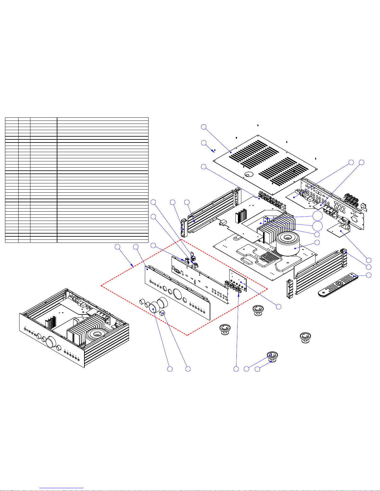
Exploded Diagram 4
Input PCB Schematic (Power Supply) 5
Input PCB Schematic (Buffers and Switches) 6
Input PCB Schematic (Tone Control) 7
Input PCB Schematic (Protection Circuitry) 8
Input PCB Schematic (Headphone Driver) 9
Input PCB Layout (Top Side) 10
Input PCB Layout (Bottom Side) 11
Input PCB Assembly BOM 12-13
Voltage Select Switch PCB Schematic 14
Voltage Select PCB Layout (Top Side) 15
Voltage Select PCB Layout (Bottom Side) 16
Voltage Select PCB Assembly BOM 17
Mains PCB Schematic 18
Front Panel PCB Schematic 19
Mains & Front Panel PCB Layout (Top Side) 20
Mains & Front Panel PCB Layout (Bottom Side) 21
Mains & Front Panel PCB Assembly BOM 22
Amp PCB Schematic (Right Channel) 23
Amp PCB Schematic (Protection) 24
Amp PCB Schematic (Power Amp) 25
Amp PCB Schematic (Left Channel) 26
Amp PCB Layout (Top Side) 27
Amp PCB Layout (Bottom Side) 28
Amp PCB Assembly BOM 29-31
Abus Module PCB Schematic 32
Abus Module PCB Layout (Top Side) 33
Abus Module PCB Layout (Bottom Side) 34
Abus PCB Assembly BOM 35
IC Pin Layout Details 36-42
3
SAFETY PRECAUTIONS & IMPORTANT NOTES
3
1. Check that the rear of the product indicates the correct supply voltage for
your area.
2. The lighting flash with the arrowhead within an equilateral
triangle is intended to alert the user or service agent to the
presence of dangerous voltages within the product enclosure that
may be of sufficient magnitude to constitute a risk of electric shock
to persons.
3. The exclamation point within an equilateral triangle is intended
to alert the user or service agent to the presence of important
operating and maintenance (Servicing) instructions in the literature
accompanying the appliance.
4. This product complies with EEC Low Voltage (73/23/EEC) and
Electromagnetic Compatibility (89/336/EEC) Directives when used and serviced
in accordance with this manual. For continued compliance all components
marked safety and EMC critical must only be replaced by Cambridge Audio
approved parts.
5. Any unauthorised design alterations or additions will void the manufacturer’s
warranty; furthermore the manufacturer cannot accept responsibility for personal
injury or property damage resulting therefrom.
6. When servicing, care should be taken to observe the original routing and
dressing of the leads and it should be confirmed that they have been returned to
normal after re-assembly.
Notes on chip component replacement
Never reuse a component that has been removed from a PCB
Notice that the minus side of a tantalum capacitor may be damaged by heat
COPYRIGHT NOTICE.
© 2005 Audio Partnership PLC. All rights reserved.
Cambridge Audio and Azur are registered trademarks for Audio Partnership PLC. This document
may not be reproduced, distributed, transmitted, displayed, published, or broadcast without the
express written prior permission of Audio Partnership PLC.
Alteration or removal of any trademark, copyright, or other notice from this content is prohibited.
Information provided in this document is provided solely for the use of official service agents in
repairing and servicing Audio Partnership PLC products.
21
17
25
10
18 (a)
8
19 (b)
20
22
16
12
23
6
14
3
1
2
4
24
5
15
11
9
13
7
Drawing ref AP P art Factory part number Desc ription
1 PY687 6560-150001-000A VOLUME KNOB ALUMINIUM SKIN AP133601 SILVER (use with PY680+PY681)
1 PY686 6560-150001-000 V OLUME KNOB ALUMINIUM SKIN AP133601 BLACK (use with P Y680+PY681)
2 PY592 6050-150004-002-02 Azur-640A SE LECTOR KNOB SILVER
2 PY593 6050-150004-002-01 Azur-640A SE LECTOR KNOB BLACK
3 PY719 6050-150012-000-01 7MM TAC SW ITCH BUTTON (BLACK)
3 PY720 6050-150012-000A01 7MM TAC SWITCH BUTTON (SILVER)
4 6050-150013-000A01 7MM PUSH S WITCH BUTTON SILVER FOR Azur-640A
4 6050-150013-000 7MM PUSH SW ITCH BUTTON BLACK FOR A zur-640A
5 6050-117821-000-02 Azur-640A CONTROL BOX BUTTON SILVER
5 6050-117821-000-01 Azur-640A CONTROL BOX BUTTON BLACK
6 PY541 6050-150010-000A01 PLASTIC FOOT SILVER
6 PY531 6050-150010-000 P LASTIC FOOT BLACK
7 PY544 6600-170100-000 FOOT PA D FOR AZUR RANGE
8 PY1058 3200-076771E000 115/230V 30V*2/3A 17V*2/0.4A Azur-540A V2 AP175704
9 PY1032 6550-150017-001-02 LARGER SIDE PANEL S ILVER PAINTED
9 PY1033 6550-150017-001-01 LARGER SIDE PANEL B LACK PAINTED
10 PY1034 6550-150037-000-02 V2 AMP TOP PANEL SILVER PAINTED
10 PY1035 6550-150037-000-01 V2 AMP TOP PANEL BLACK PA INTED
11 PY1036 8554-015010-701 LARGER SUPPORT FRONT ASSY (W ITH TWO BRASS INSERTS)
12 PY1037 8554-015020-701 LARGER SUPPORT REAR ASSY (WITH TWO BRASS INSERTS)
13 PY1059 8554-015001-302 A zur-540A V2-Silver AMP FRONT PANEL A SSY
13 PY1060 8554-015011-302 A zur-540A V2-Black AMP F RONT PANEL ASS Y
14 PY1040 9464-015002-041 A zur-640A/540A V2 PIC CONTROL BOARD ASS Y REV A
15 PY1041 9464-015002-171 A zur-640A/540A V2 POWER SW ITCH PCB REV A
PY1042 9464-015002-191 Azur-640A/540A V2 LED P CB ASSY REV A
16 PY1061 9454-015002-071 A zur-540A V2 POWER INPUT BOARD ASSY REV A
17 PY1062 9454-015002-091 A zur-540A V2 AMP POWE R PCB ASSY REV A
18 PY1045 9464-015002-001 640A/ 540A V2 PROTECTION CIRCUITRY PCB-A ASSY REV A
19 PY1046 9464-015002-101 640A/ 540A V2 PROTECTION CIRCUITRY PCB-B ASSY REV A
20 PY1047 9464-015002-331 A zur-640A/540A A-Bus hub PCB AS SY REV A
21 PY1048 9464-015002-341 A zur-640A/540A V2 INPUT PCB ASSY REV A
22 PY1049 9464-015002-541 A zur-540A/640A V2 SPEAKER CONN. BOARD ASSY REV A
23 PY944 9805-054010-001 AZUR-540A/C,640A/C V2.0 REMOTE CONTROL ASSY REV A
PY945 6040-150002-000-01 BATTERY-DOOR FOR Azur R/C BLACK PAINTED
24 PY1056 6550-150021E001A03 A ZUR 540A V2.0 FRONT PANEL-Silver (Metal only)
24 PY1054 6550-150021E001-03 AZUR 540A V2.0 FRONT PANEL-Black (Metal only )
25 PY515 7002-608010-001 Screw M2.6 x 8 M/C Torx Recessed 1/K Head Blac k
25 PY516 7002-608010-006 Screw M2.6 x 8 M/C Torx Recessed 1/K Head En-Plated
PY1051 5100-641500E300 AZUR 540A/640A V2 USE R'S MANUAL (AP183031)
To enhance viewing, please print to A3 4
Cambridge Audio Azur 540A V2.0 Amplifier
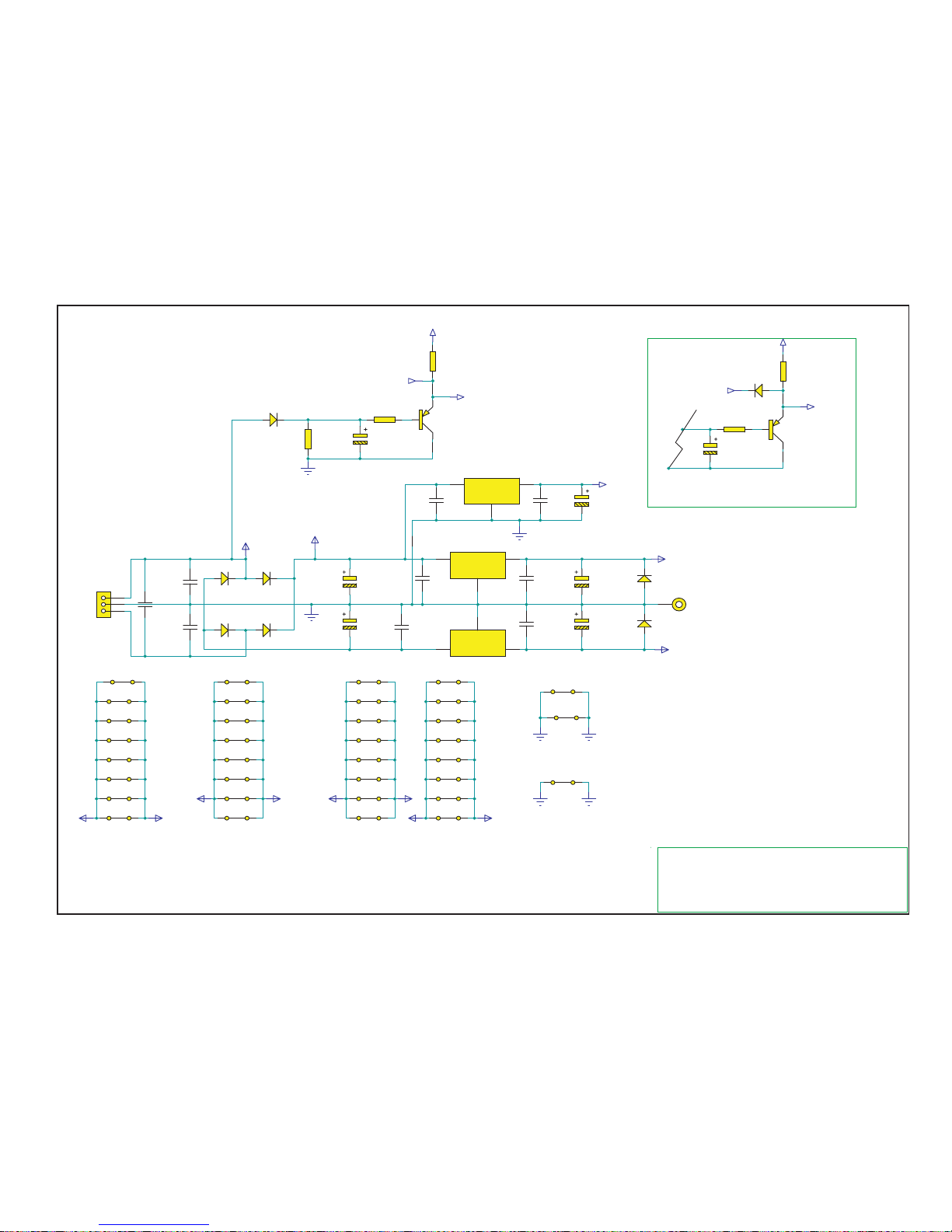
AP17649/5 Input PCB Schematic (Power Supply)
VI
1
VO
3
GND
2
U3
L7805
C26
47u 16V
VI
1
VO
3
GND
2
U4
L7815
VI
2
VO
3
GND
1
U2
L7915
+5V
DGND
D2
1N4004D31N4004
D4
1N4004D51N4004
C35
100N 100V X7R
C37
100N 100V X7R
C27
100N 50V X7R
C25
100N 50V X7R
C31
47N PE 63V
C34
47N PE 63V
C30
47N PE 63V
C29
47N PE 63V
C28
100U 25V EL 105
C98
100U 25V EL 105
GENERAL NOTES
1.
2.
3.
4.
5.
1
2
3
CN8
3,96MM 3W ST HEADER
C36
100N 100V X7R
Unreg for Relays
LK40
LK10MM
Main
+15V
-15V
LK86
LINK10MM
LK83
LINK10MM
LK79
LINK10MM
LK75
LINK10MM
LK71
LINK10MM
LK63
LINK10MM
LK67
LINK10MM
-15V
-15V
LK82
LINK10MM
LK78
LINK10MM
LK74
LINK10MM
LK70
LINK10MM
LK64
LINK10MM
LK66
LINK10MM
+15V
+15V
LK88
LINK10MM
LK47
LINK10MM
LK44
LINK10MM
LK41
LINK15MM
LK42
LINK15MM
+15V
+15V
-15V
-15V
LK13
LINK10MM
LK6
LINK15MM
LK7
LINK15MM
LK12
LINK15MM
LK17
LINK15MM
LK23
LINK10MM
LK26
LINK10MM
LK28
LINK10MM
LK22
LINK10MM
LK29
LINK10MM
LK30
LINK10MM
LK32
LINK15MM
LK31
LINK10MM
LK34
LINK15MM
C32
1000U 35V EL
C33
1000U 35V EL
LK50
LINK15MM
LK48
LINK15MM
AC Sense
R55
4k7
C38
1U 25V
D1
1N4004
R56
4k7
Q7
BC327
R114
4k7
+5V
PIC Standby Relay
Standby Relay
Main
LK98
LINK10MM
J7
TERMINAL
Main Main
Rev2:D8Removed,LK105and106added.
LK105
LK10MM
LK106
LK10MM
D9
1N4004
D10
1N4004
Rev4:D9andD10added.
C38
1U 25V
R56
4k7
Q7
BC327
R114
4k7
+5V
PIC Standby Relay
Standby Relay
LK105
LK10MM
LK106
LK10MM
D8
1N4148
Revision1
To enhance viewing, please print to A3 5
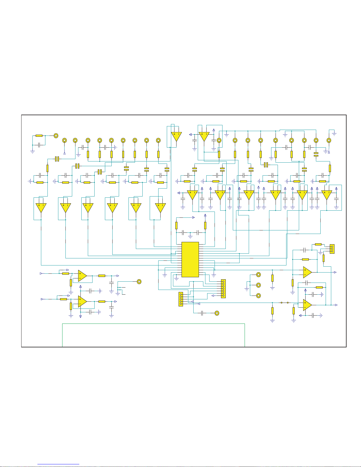
Cambridge Audio Azur 540A V2.0 Amplifier
AP17649/5 Input PCB Schematic (Buffer and Switches)
Abus GND
GENERAL NOTES
1.
2.
3.
4.
5.
2
3
1
8 4
U9:A
NE5532N
R112
220R 1/8W
R111
220R 1/8W
6
5
7
U9:B
NE5532N
2
3
1
8 4
U12:A
NE5532N
6
5
7
U12:B
NE5532N
-15V
+15V
+15V
-15V
+15V
-15V
U6
U6
SW GND
LCh In
RCh In
LCh Out
RCh Out
L
R
Vss
1
L-S1
2
L-S2
3
L-S3
4
L-COM1
5
L-S4
6
L-S5
7
L-S6
8
L-COM2
9
L-S7
10
L-S8
11
L-COM3
12
ST
13
GND
14
Vdd
28
R-S1
27
R-S2
26
R-S3
25
R-COM1
24
R-S4
23
R-S5
22
R-S6
21
R-COM2
20
R-S7
19
R-S8
18
R-COM3
17
DATA
16
CLK
15
U11
TC9163AF
6
CN14:D
AV4-8,4-9
3
CN13:B
AV4-8,4-9
6
CN13:D
AV4-8,4-9
Aux
CD
DAB
DVD
MD
TO1
TO2
TM
PO
3
CN12:B
AV4-8,4-9
6
CN12:D
AV4-8,4-9
3
CN15:B
AV4-8,4-9
PreOut Left
PreOut Right
PreOut Left
PreOut Right
6
CN15:D
AV4-8,4-9
1
2
CN16:A
AV2-8,4-9
SW GND
3
CN16:B
AV2-8,4-9
2
3
1
84
U14:A
NE5532N
-15V
+15V
C67
47n 63V PE
C68
47n 63V PE
R96
47k 1/8W
2
3
1
84
U13:A
NE5532N
R93
47k 1/8W
2
3
1
84
U15:A
NE5532N
-15V
+15V
C71
47n 63V PE
C72
47n 63V PE
R89
47k 1/8W
2
3
1
84
U16:A
NE5532N
R85
47k 1/8W
2
3
1
84
U17:A
NE5532N
-15V +15V
C76
47n 63V PE
C75
47n 63V PE
R81
47k 1/8W
2
3
1
84
U18:A
NE5532N
R73
47k 1/8W
6
5
7
U13:B
NE5532N
-15V
+15V
C70
47n 63V PE
C69
47n 63V PE
R91
47k 1/8W
6
5
7
U14:B
NE5532N
R95
47k 1/8W
6
5
7
U16:B
NE5532N
-15V
C74
47n 63V PE
C73
47n 63V PE
R83
47k 1/8W
6
5
7
U15:B
NE5532N
R87
47k 1/8W
6
5
7
U18:B
NE5532N
-15V
+15V
C44
47n 63V PE
C45
47n 63V PE
R110
47k 1/8W
6
5
7
U17:B
NE5532N
R79
47k 1/8W
C91
47N PE 63V
C92
47N PE 63V
C41
47N 63V PE
C42
47N 63V PE
R104
1k8
R105
1k8
R103
1k8
R102
1k8
C90
10P 50V NPO
C93
10P 50V NPO
R99
100R
R98
100R
C88
100N 50V X7R
C89
100N 50V X7R
R109
1k 1/8W
R78
1k 1/8W
R82
1k 1/8W
R86
1k 1/8W
R90
1k 1/8W
R94
1k 1/8W
R97
1k 1/8W
R92
1k 1/8W
R88
1k 1/8W
R84
1k 1/8W
R80
1k 1/8W
R72
1k 1/8W
C83
100p 50V NP0
C48
100p 50V NP0
C53
100p 50V NP0
C57
100p 50V NP0
C61
100p 50V NP0
C65
100p 50V NP0
C66
100p 50V NP0
C62
100p 50V NP0
C58
100p 50V NP0
C54
100p 50V NP0
C50
100p 50V NP0
C46
100p 50V NP0
R75
220R 1/8W
R76
220R 1/8W
R74
220R 1/8W
R77
220R 1/8W
3
CN14:B
AV4-8,4-9
1
2
CN14:A
AV4-8,4-9
4
5
CN14:C
AV4-8,4-9
1
2
CN13:A
AV4-8,4-9
4
5
CN13:C
AV4-8,4-9
1
2
CN12:A
AV4-8,4-9
4
5
CN12:C
AV4-8,4-9
1
2
CN15:A
AV4-8,4-9
4
5
CN15:C
AV4-8,4-9
LK60
LINK15MM
LK51
LK15MM
+15V
C64
10U NP 16V
C63
10U NP 16V
C60
10U NP 16V
C59
10U NP 16V
C56
10U NP 16V
C55
10U NP 16V
C52
10U NP 16V
C51
10U NP 16V
C49
10U NP 16V
C47
10U NP 16V
C81
10U NP 16V
C82
10U NP 16V
LK62
LK10MM
LK57
LK10MM
LK56
LK15MM
LK53
LK15MM
LK55
LK10MM
LK54
LK10MM
LK92
LK10MM
LK90
LK15MM
LK91
LK15MM
LK9
LK15MM
LK8
LK15MM
U6
U6
LK89
LK15MM
LK99
LK15MM
LK97
LK10MM
LK93
LK10MM
LK94
LK10MM
R100
470k
R101
470k
LK95
LK10MM
LK96
LINK15MM
LCh HP Out
RCh HP Out
LK5
LK15MM
LK43
LK15MM
1
2
3
CN10
2,5MM 3W ST HEADER
ABUS Audio Out
R106
560R
R107
560R
1
2
3
4
5
6
7
CN5
2,5MM 7W ST HEADER
To PIC
Clock
Data
Strobe
DGndfromPIC
ControlBusIR
ABUSIR
AmpMute
ControlBusIR
ABUSIR
ABUSStatus
RCh
GND
LCh
1
2
3
4
5
CN9
2,5MM 5W ST HEADER
ABUS Control Signals
ABUSPCBDGnd
LK101
LK10MM
C87
1N 50V NP0
J1
TERMINAL
R113
47R no stuff
C86
1N 50V NP0 no stuff
J2
TERMINAL
C80
100p 50V NP0
C78
100p 50V NP0
U6
U6
C77
100p 50V NP0
C79
100p 50V NP0
U6
U6
C85
100P 50V NP0
C84
100P 50V NP0
2
3
1
84
U10:A
NE5532N
-15V
+15V
C40
47n 63V PE
C39
47n 63V PE
U6 U6
6
5
7
U10:B
NE5532N
U6
U6
U6
LK49
LK15MM
LK52
LINK15MM
LK58
LK10MM
LK61
LK10MM
LK59
LINK15MM
ABUSPCB+5V
+5VOLTS
LK100
LK15MM
LK85
LK10MM
LK87
LK10MM
LK68
LK10MM
LK69
LK10MM
LK73
LK10MM
LK77
LK10MM
LK81
LK10MM
LK84
LK10MM
LK80
LK10MM
LK76
LK10MM
LK72
LK10MM
LK65
LK10MM
R58
1k8
R59
1k8
J4
TERMINAL
J5
TERMINAL
J6
TERMINAL
J8
TERMINAL
R61
3k6
U6
R60
3k6
U6
U6
Rev1:ResistorsR72,78,80,82,84,86,88,90,92,94,97,109changedto75R
GNDLinksonunderside
Amp Mute
Standby Relay
Rev4:ResistorsR72,78,80,82,84,86,88,90,92,94,97,109changedto1k
To enhance viewing, please print to A3 6
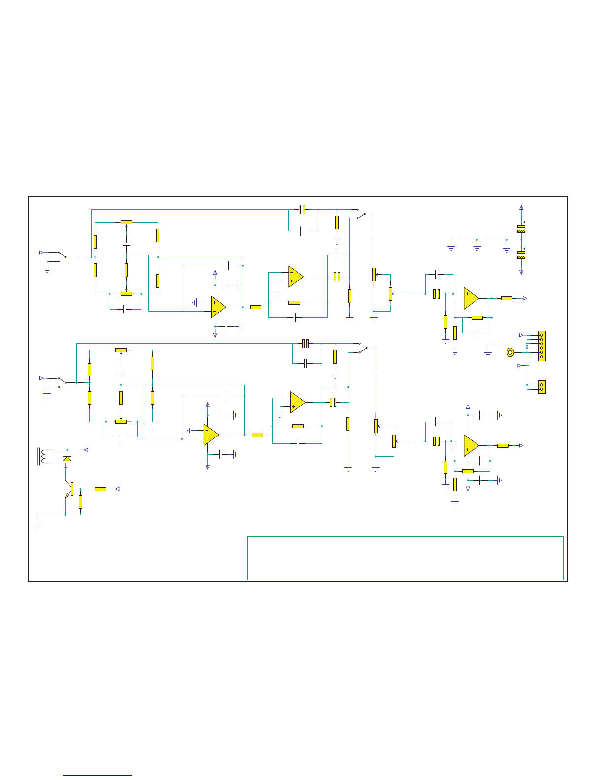
Cambridge Audio Azur 540A V2.0 Amplifier
AP17649/5 Input PCB Schematic (Tone Control)
GENERAL NOTES
1.
2.
3.
4.
5.
R20
4k7
R23
1k1
R24
1k1
R17
2k2
R19
2k2
SW2:A
SW-DPDT
Tone Defeat
Out
-15V
+15V
R36
2k2
R35
2k2
R22
4k7
R26
1k1
R25
1k1
R18
2k2
R21
2k2
SW2:B
SW-DPDT
Tone Defeat
-15V
+15V
R37
2k2
R38
2k2
U2
out
Out
-15V
+15V
U2
U4U4
OutOut
U2
+15V
-15V
2
3
1
8 4
U6:A
NE5532N
6
5
7
U6:B
NE5532N
2
3
1
8 4
U5:A
NE5532N
6
5
7
U5:B
NE5532N
U2
6
5
7
U7:B
NE5532N
2
3
1
84
U7:A
NE5532N
RCh In
LCh In
RCh Out
LCh Out
U2
U4
U4
R15
150k
R14
150k
R16
150k
R13
150k
4 6
5
VR3:B
20K MOTORISED DUAL POT
1 3
2
VR3:A
20K MOTORISED DUAL POT
4 6
5
VR4:B
MN20K BALANCE
13
2
VR4:A
MN20K BALANCE
13
2
VR2:A
B5K LINEAR
46
5
VR2:B
B5K LINEAR
13
2
VR1:A
B5K LINEAR
46
5
VR1:B
B5K LINEAR
1
2
3
4
5
6
CN3
H6 2.54mm
TO POWER AMP
C5
47U NP 16V
C11
47U NP 16V
C4
47U NP 16V
C7
47U NP 16V
RCh Out
LCh Out
C103
47N 63V PE
C102
47N 63V PE
C14
47N 63V PE
C16
47N 63V PE
C9
47N 63V PE
C10
47N 63V PE
C18
10P 50V NPO
C23
10P 50V NPO
C8
10P 50V NPO
C13
10P 50V NPO
C19
1N5 63V PE
C20
1N5 63V PE
C22
680N 63V PE
C21
680N 63V PE
LK37
LK15MM
U4
LK25
LK10MM
LK24
LK10MM
LK21
LK15MM
LK19
LK15MM
R33
22R
R34
22R
LK35
LINK15MM
LK20
LK15MM
LK27
LK10MM
LK18
LK15MM
R29
22k
R31
22k
Out
Out
C6
10N PP 63V
C12
10N PP 63V
C3
10N PP 63V
C24
10N PP 63V
C104
10U NP 16V
C101
10U NP 16V
C105
10N PP 63V
C100
10N PP 63V
LK36
LINK15MM
R32
1k5
R30
3k
Out
R27
1k5
R28
3k
Out
C106
10P 50V NPO
C99
10P 50V NPO
C15
100U 25V EL
C17
100U 25V EL
LK33
LK15MM
J3
TERMINAL
1
2
CN17
2MM 2W ST HEADER
3
4
5
RL1:B
ME2-5S
6
7
8
RL1:C
ME2-5S
1
2
RL1:A
ME2-5S
+5VOLTS
D8
1N4004
Q9
MPSA14
R122
10k
R123
1k
MAIN
Amp Mute
Rev2:RL1,D8,Q9,R122,R123,LK104,107-109added.
LK16
LK10MM
LK104
LK10MM
LK107
LK10MM
LK108
LK15MM
LK109
LK15MM
To enhance viewing, please print to A3 7
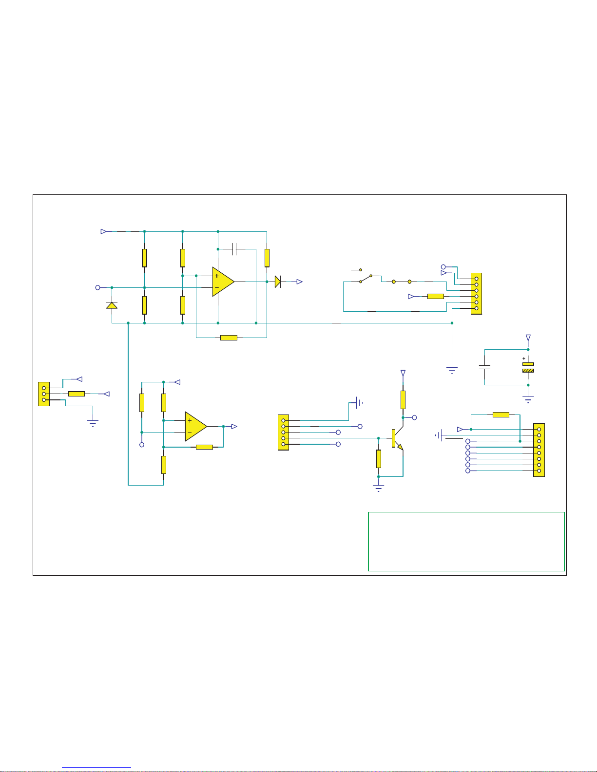
Cambridge Audio Azur 540A V2.0 Amplifier
AP17649/5 Input PCB Schematic (Protection Circuitry)
+5Volts
R66
1k
For 1mA
R64
10k
R67
100R
R65
2R7
DGND
3
2
1
84
U8:A
LM393
D7
1N4148
+5V
Speaker short circuit tester
R69
4k7
(Open Collector Output)
Senses a DC resistance of 2 ohms or less
D6
1N4004
PIC VI/Short
C43
100N 50V X7R
Speaker Test
DGND
+5V
SW1:B
SW-DPDT
TAPE
SPEAKER B SWITCHING (for relay)
Speaker Test
Speaker A Relay
Unreg for Relays
1
2
3
4
5
6
CN11
2,5MM 6W ST HEADER
To Speaker PCB CN1
PIC Standby Relay
Unreg for Relays
DGND
1
2
3
CN7
2,5MM 3W ST HEADER
R57
220R 2W Carbon
R108
220R 2W Carbon
PIC VI/Short
PIC DC
PIC CLIP
PIC Temp
Speaker A Relay
PIC Standby Relay
1
2
3
4
5
6
7
8
CN6
2,5MM 8W ST HEADER
To PIC
GENERAL NOTES
1.
2.
3.
4.
5.
MainsPCBControl
SpeakerPCBControl
PICProtectionsignals
SpeakerCableShortCircuitDetector
LK103
LK10MM
LK14
LK10MM
LK15
LK10MM
5
6
7
U8:B
LM393
LK102
LK10
LINK15MM
LK46
LK11
LINK15MM
LK45
LK10MM
1
2
3
4
5
CN4
2,5MM 5W ST HEADER
DGND
PIC VI/Short
PIC DC
PIC CLIP
Temp Sense
R116
10k
R115
10k
DGND
+5V
PIC Temp
R63
910R
910 / (910 + 10k) with ZP221A501E
voltage gives 100deg C cutout
+5Volts
Temp Sense
R71
4k7
R70
10k
R117
4k7
Open Collector Output
Q8
BC337
LK39
LK10MM
LK38
R68
100k
R62
no stuff
C108
100N 50V X7R
C107
100U 16V EL
DGND
+5V
Rev3:R65Changedfrom10Rto8R2
Rev4:R65Changedfrom8R2to4R7
Rev5:R65Changedfrom4R7to2R7
To enhance viewing, please print to A3 8
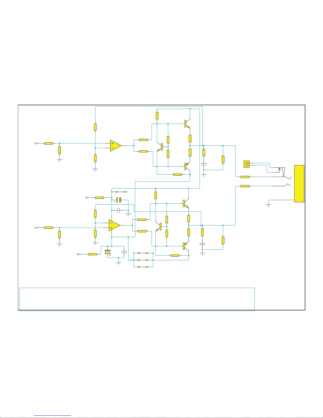
Cambridge Audio Azur 540A V2.0 Amplifier
AP17649/5 Input PCB Schematic (Headphone Driver)
Main
+15V
-15V
R54
10R
R53
10R
6
5
7
U1:B
NE5532N
R8
1R
R6
1R
R41
2k7
R40
3k3
R43
560R
R42
560R
R39
5k6
R7
5k6
Q6
BD139
Q5
BD139
Q4
BD140
R9
180R
Main
RSW1
RSW2
R
L
GND
2
3
1
7
8
CN1
HEADPHONE JACK
Main
C96
47N 63V PE
C95
47N 63V PE
2
3
1
84
U1:A
NE5532N
R3
1R
R1
1R
R46
2k7
R45
3k3
R48
560R
R47
560R
R44
5k6
R2
5k6
Q3
BD139
Q2
BD139
Q1
BD140
R4
180R
Main
GENERAL NOTES
1.
2.
3.
4.
5.
R11
10R 2W
R12
10R 2W
RCh HP Out
R52
100R
R51
No Stuff
Main
LCh HP Out
R49
100R
R50
No Stuff
Main
C97
470U 25V EL
C94
470U 25V EL
R5
360R
R10
360R
C2
10N 63V PE
C1
10N 63V PE
Main
LK2
LINK10MM
LK1
LINK10MM
LK3
LINK10MM
LK4
LINK10MM
1
2
CN2
2,5MM 2W ST HEADER
R118
1k5
R119
3k
R120
1k5
R121
3k
Main
Main
Rev1:ResistorsR118-121added
(RchOut)
(LchOut)
Rev2:ResistorsR11,R12,R118-121valueschanged.
To enhance viewing, please print to A3 9
Cambridge Audio Azur 540A V2.0 Amplifier
AP17649/4 Input PCB Board Layout (Top Side)
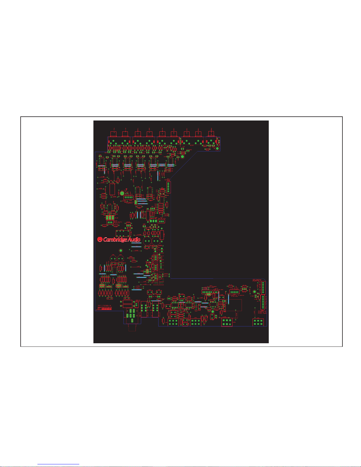
Super Hi-Fidelity Ultra Linear Preamp S tage
To enhance viewing, please print to A3 10
Cambridge Audio Azur 540A V2.0 Amplifier
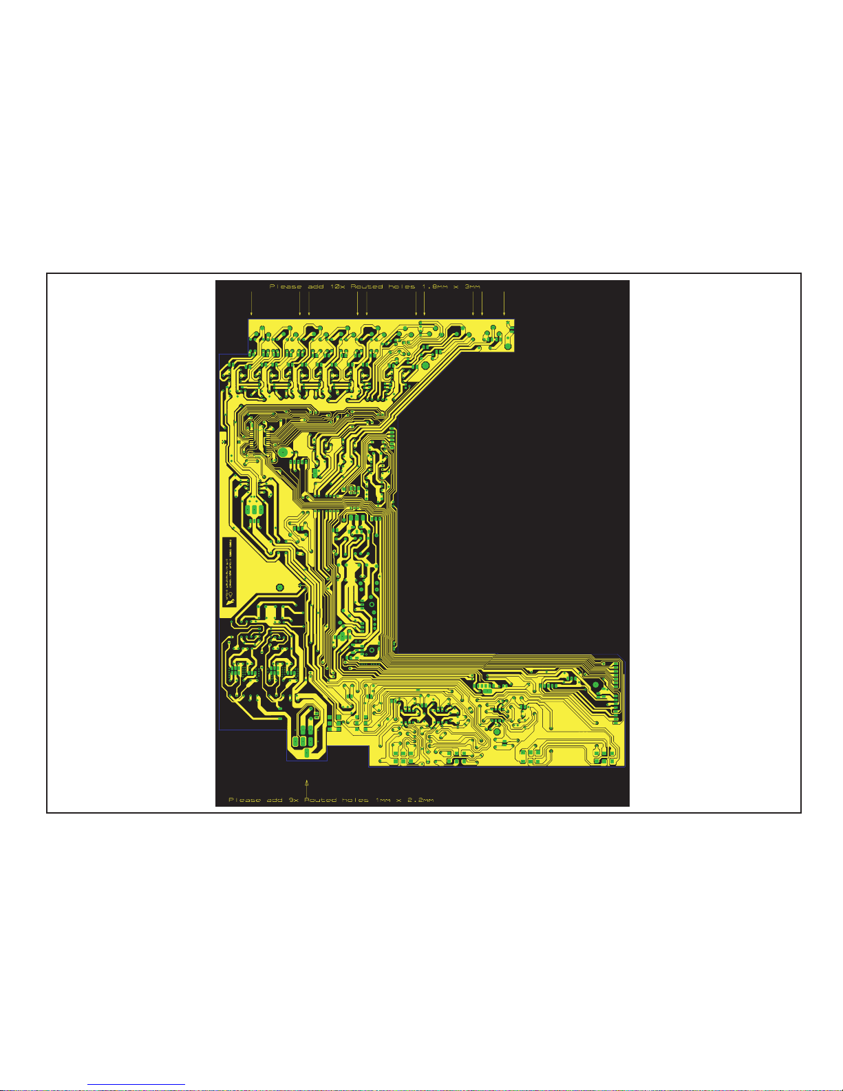
AP17649/4 Input PCB Board Layout (Bottom Side)
To enhance viewing, please print to A3 11

A
y)
K
)
)
)
)
K
)
)
K
)
)
y
y
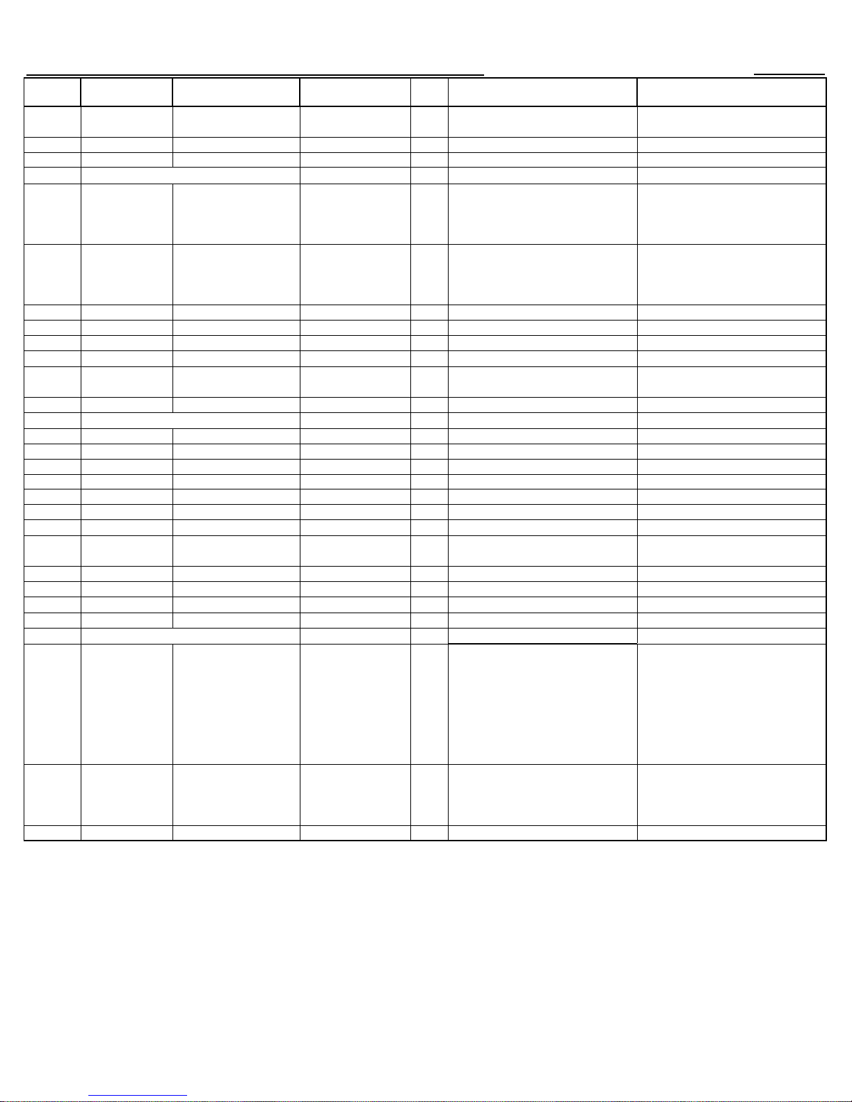
Cambridge Audio Azur 540A V2.0 Amplifier Input PCB Assembly BOM
12
P Part
No
Value Description/Type Factory Part No. Qty Component Ident Notes
RESISTORS
1R 0.25W metal film 4 R1, 3, 6, 8.
2R7 0.25W metal film 1 R65
10R 0.25W metal film 2 R53, 54
22R 0.25W metal film 2 R33, 34
100R 0.25W metal film 5 R49, 52, 67, 98, 99.
180R 0.25W metal film 2 R4, 9
360R 0.25W metal film 2 R5, 10
560R 0.25W metal film 6 R42, 43, 47, 48,106,107
910R 0.25W metal film 1 R63
1
1K1 0.25W metal film 4 R23-26
1K5 0.25W metal film 4 R27, 32, (118,120)
1K8 0.25W metal film 6 R58, 59, 102-105.
2K2 0.25W metal film 8 R17-19, 21, 35-38
2K7 0.25W metal film 2 R41, 46
3K 0.25W metal film 4 R28, 30, R119, (R121)
3K3 0.25W metal film 2 R40, 45
3K6 0.25W metal film 2 R60, 61
4K7 0.25W metal film 8 R20, 22, 55, 56, 69, 71, 114, 117
5K6 0.25W metal film 4 R2, 7, 39, 44
10
22
100K 0.25W metal film 1 R68
150K 0.25W metal film 4 R13-16
470K 0.25W metal film 2 R100, 101
1k 0.125W metal film 12
220R 0.125W metal film 6 R74-77, 111, 112.
47K 0.125W metal film 12
10R 2W Carbon 2 R11,12
220R 2W Carbon 2 R57, 108
0.25W metal film 2 R66,(R123
0.25W metal film 5 R64, 70, 115, 116,(122
0.25W metal film 2 R29, 31
R72, 78, 80, 82, 84, 86, 88, 90, 92, 94,
97, 109.
R73, 79, 81, 83, 85, 87, 89, 91, 93, 95,
96, 110,
CAPACITORS
10pF 50V NP0 Ceramic 1181-100042-000 8 C8, 13, 18, 23, 90, 93, 99, 106.
100pF 50V NP0 Ceramic 1181-101042-000 18
1nF 50V Ceramic 1100-102043-000 1 C87
100nF 50V Ceramic 1100-104043-000 6 C25, 27, 43, 88, 89, 108
100nF 100V Monolythic Ceramic 1106-104064-001 3 C35, 36, 37.
1.5nF 63V Polyester film 2 C19, 20
10nF 63V Polyester film 1117-103052-000 2 C1, 2
47nF 63V Polyester film 1117-473053-000 30
680nF 63V Pol
10nF 63V Polypropylene film 6 C3, 6, 12, 24, 100, 105
10uF 16V
47uF 16V
1uF 25V Polarised Electrolytic 1102-107024-000 1 C38
47uF 16V Polarised Electrolytic 1102-470014-000 1 C26
100uF 16V Polarised Electrolytic 1102-101014-000 1 C107.
100uF 25V Polarised Electrolytic 1102-101024-000 2 C15, 17
ester film 2 C21, 22
Non Polarised
Electrol
Non Polarised
Electrolytic
tic
1105-100013-000 14
C46, 48, 50, 53, 54, 57, 58, 61, 62, 65,
66, 77-80, 83, 84, 85
C9, 10, 14, 16,29-31, 34, 39, 40, 41,
42, 44, 45, 67-76, 91,92,95, 96, 102,
103
C47, 49, 51, 52, 55, 56, 59, 60, 63, 64,
81, 82, 101, 104
4 C4, 5, 7, 11,
AP17652/5
See Input Schematic (Protection
Circuitr
See Input Schematic (Tone Control
See Input Schematic (Headphone
Driver
See Input Schematic (Headphone
Driver
See Input Schematic (Tone Control
See Input Schematic (Buffers and
Switches
See Input Schematic (Headphone
Driver
Note: resistors, capacitors and other 'generic' electronics components are not usually stocked by
the manufacturer. Please obtain these locally.
A
Cambridge Audio Azur 540A V2.0 Amplifier Input PCB Assembly BOM
p
p
)
)
k
(
)
y
)
13
P Part
No
PY219 BC327-25 PNP Signal 1301-327000-100 1 Q7
PY214 BC337-25 NPN Signal 1300-337000-100 1 Q8
PY319 1N4004 Rectifier 1401-140040-000 9 D1-6,(D8, D9, D10)
PY759 1N4148 Signal 1401-141480-000 1 D7
PY108 NE5532N 4155-320052-900 13 U1, 5-7, 9, 10, 12-18
PY539 LM393 4139-300052-600 1 U8
PY476 TC9163AF 4191-630103-000 1 U11
PY1013 20kA
PY045 2P2T Push Switch 2402-020200-010 2 SW1, 2
PY584 5V Rela
Value Description/Type Factory Part No. Qty Component Ident Notes
100uF 25V
470uF 25V Polarised Electrolytic 2 C94, 97
1000uF 35V Polarised Electrolytic 1102-102034-000 2 C32, 33
105 degree Polarised
Electrolytic
2 C28, 98.
TRANSISTORS
BD140 PNP Low power 2 Q1, 4
BD139 NPN Low power 4 Q2, 3, 5, 6,
NPN Darlington 1300-140000-100 1 Q9 See Input Schematic (Tone Control
DIODES
INTEGRATED CIRCUITS
L7915CV 1 U2
L7805 1 U3
L7815CV 1 U4
POTS
Motorised Dual Volume
Pot
MN20
5kB Dual Linear Pot 1062-002518E130 2VR1, 2 High Torque
Dual Balance Pot 1062-003518E160 1VR4 High Torque
1062-003511E110 1 VR3 High Torque
SWITCH
MISCELLANEOUS
LK1-4, 13, 22, 23, 26, 28-31, 44, 47,
63, 64, 66, 67, 70, 71, 74, 75, 78, 79,
82, 83, 86, 88, 98, 14-16,24, 25, 27,
70
38-40, 45, 46, 54, 55, 57, 58, 61, 62,
65, 68, 69, 72, 73, 76, 77, 80, 81, 84,
85, 87, 92-95, 97, 101103,(104,105,106,107)
LK5, 8, 9, 18-21, 33, 37, 43, 49, 51,
53, 56, 89-91, 99, 100, 6, 7, 10-12, 17,
39
32, 34-36, 41, 42, 48, 50, 52, 59, 60,
108,109
96,
LINK10mm
LINK15mm
24SWG Tinned Copper
Wire
24SWG Tinned Copper
Wire
4050-000005-002 1 RL1 See Input Schematic (Tone Control
AP17652/5
Q1 and Q2 must be thermally coupled
and Q4 and Q5 must be thermally
coupled, please see misc section for
arts
Q1 and Q2 must be thermally coupled
and Q4 and Q5 must be thermally
coupled, please see misc section for
arts
See Input Schematic (Power Supply &
Tone Control
See Input Schematic (Power Supply &
Tone Control)
See Input Schematic (Tone Control)
Note: resistors, capacitors and other 'generic' electronics components are not usually stocked by
the manufacturer. Please obtain these locally.
 Loading...