

Cambridge Audio AR30 V2 Service Manual
1
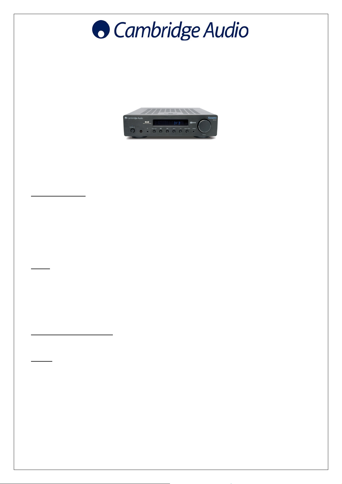
AR30 V2
Issue Date: February 2011
________________________________________________________________________
SERVICE MANUAL
________________________________________________________________________
Technical specifications
AR30 v2 specifications
Amplifier section
Power output 40 watts per channel (into 8Ω)
THD <0.05% 20Hz-20kHz @ 80% max power
<0.009% @ 1kHz 10w
Frequency response 10Hz - 50kHz +/-1dB
S/N ratio (ref 1w) >80dB ‘A’ weighted
Line input impedances 47kohms (CD, DVD, Aux and MP3 inputs)
Tone controls +/-12dB @ 100Hz and 10kHz (shelving)
Headphone output 3.5mm stereo mini jack 32-600ohm
headphones recommended
Tuners
Bands AM (530-1710kHz)
FM/VHF (87.5MHz to 108MHz)
Aerial inputs FM 75ohms, Coaxial. AM 300 ohms wire
loop/single wire.
Signal to noise 80dB typical (DAB)
60dB typical (FM)
Distortion <0.01% @1kHz 2V rms o/p (DAB)
<0.2% @ 1kHz 50kHz deviation (FM mono)
<0.6% @ 1kHz 50kHz deviation (FM stereo)
DD30 docking station for iPod
THD <0.009% @ 1kHz
S/N ratio <-80dB re 2V output.
General
Trigger Outputs 3x 12V @ 30mA, 3.5mm jack, Tip positive.
Corresponding to CD, DVD and Aux inputs
Power Supply AR30-EU: 230V AC~ 50Hz (UK/EU)
AR30-CU: 115V AC~ 60Hz (CU/US)
Max. power consumption 300W
Standby power consumption <1W
Dimensions 270 x 67 x 285mm (WxHxD)
Weight 4.0kg (8.6lbs)
Gallery Court Hankey Place London SE1 4BB UK
Tel: +44 (0)20 7940 2200 Fax: +44 (0)20 7940 2233

TABLEOFCONTENTS
2
Specifications_____________________________________________________________1
TableofContents__________________________________________________________2
FrontPanelControls_______________________________________________ _________3‐4
RearPanelConnections_____________________________________________________5‐6
SafetyInstructions_________________________________________________________7‐10
ExplodedDiagram_________________________________________________________11
FrontPanelAssembly_______________________________________________ ________12
PartsTable_______________________________________________________________13
VFDSchematic____________________________________________________________14
DisplayTop_______________________________________________________________15
DisplayBottom____________________________________________________________16
AmpSchematic______________________________________________________ ______17
AmpTop_________________________________________________________________18
AmpBottom______________________________________________________________19
PowerSchematic__________________________________________________________20
PowerLayout Top_____________________________________________________________21
Power Layout Bottom_______________________________________________________22
BillofMaterials___________________________________________________________23‐37
ICDetails_______________________________________________________________38‐43
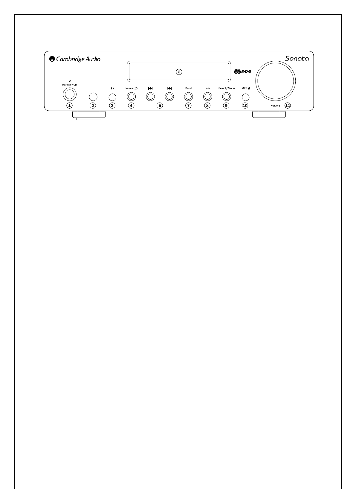
Front panel controls
3
1. Standby/On
Switches the unit between a low power standby mode (indicated by dim power LED) and on
(indicated by bright power LED). Standby is a low power mode where the power consumption is
less than 3 Watts. The unit may be left in standby mode when not in use.
2. Infrared sensor
Receive IR commands from the supplied remote control. A clear unobstructed line of sight
between the remote control and the sensor is required.
3. Phones
Allows for the connection of stereo headphones with a 3.5mm jack plug. Headphones with an
impedance of between 32 and 600 ohms are recommended.
Note: Plugging in headphones will automatically mute the loudspeaker output.
4. Source
Press to cycle through the available input sources such as tuner, MP3, CD, DVD and aux inputs.
5. Skip/Scan
Sonata AR30 v2
– In preset mode, steps up or down through the user-stored presets.
– In manual mode, steps through the frequency band, for fine-tuning. If button is held, the unit will
search for the next station with a strong signal.
Sonata DR30
– In preset mode, steps up or down through the user-stored presets.
– In FM manual mode, steps through the frequency band, for fine-tuning. If button is held, the unit
will search for the next station with a strong signal.
– In DAB manual mode, browse through the available stations.
Note:
– When MP3 input is selected, and an iPod is inserted into the attached DD30 dock, the
buttons will skip through the track lists. Press and holding the buttons will scan through the
current track.
– When Preset Mode is activated, the unit will automatically tune to the first available preset.
6. Display
Used to display information such as station name and program type for DAB broadcasts and FM
broadcasts with RDS/RBDS. Also provides feedback on volume, source, and various other data.
7. Band
Press to switch between FM, AM and SIRIUS bands (if a SIRIUS module is attached) on AR30, or

Front panel controls
4
DAB and FM bands on DR30.
8. Info
Changes the display mode to allow the user to view different information. In tuner mode, data
varies depending on the type of broadcast, and signal quality. When in a non-tuner mode,
pressing the Info button will briefly display the clock time, before returning to show the current
source.
9. Select/Mode
In tuner mode, pressing once will toggle the tuning mode between preset and manual.
In presets mode, the unit will automatically tune to the first available preset in the band.
Alternatively, you may press and hold to store the current station in the preset bank. Use the
keys or rotate the Volume control to select the preset location where you wish to store the
preset, and press Select/Mode again to confirm.
10. MP3 Input
This source input allows you to connect a portable audio device such as an MP3 player directly
into the front of the unit using the 3.5mm stereo-jack (labelled ‘MP3 In’). Select the MP3 input
source using the Source button or direct MP3 button on the remote to listen to your portable audio
device.
Note: Plugging a source into the front panel MP3 input overrides the DD30 docking station (which
is also selected by selecting the MP3 source via the remote control or front panel Source button).
Simply remove the jack from the front panel socket to automatically re-enable the DD30 docking
station as the MP3 source.
There is no need to unplug the DD30 docking station whilst using the front panel MP3 input and it
will continue to charge a docked iPod as usual.
11. Volume control
Use to increase or decrease the level of the sound from the outputs of the unit. This controls the
volume level of the loudspeakers, subwoofer and headphones. It does not affect the 'Rec Out'
output.
It is also used to change the value of the selected settings in audio setup and advanced setup
menus.
Press once to enter the audio setup menu. Press and hold to enter the advanced setup menu.
See later section in this manual.
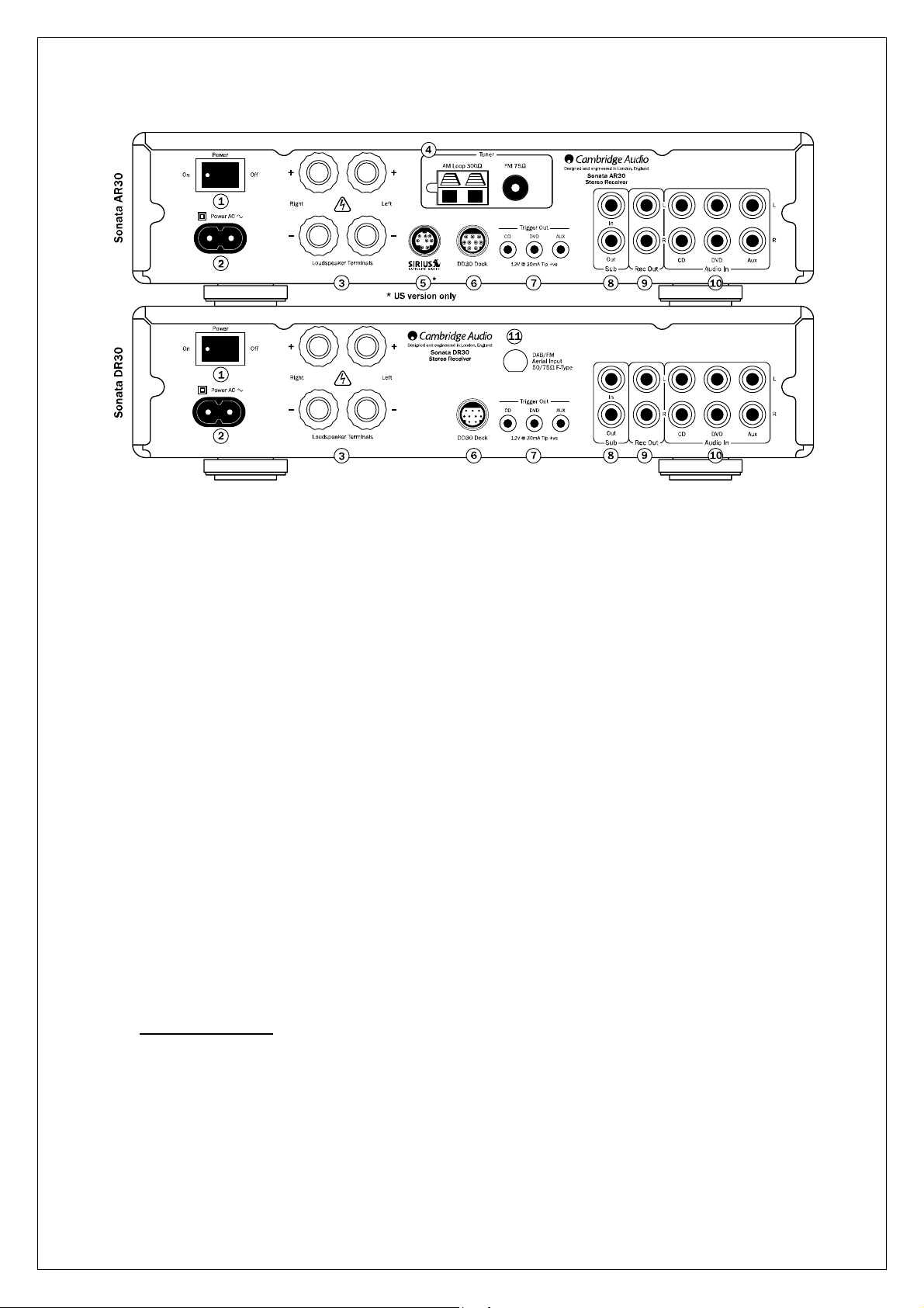
Rear panel connections
5
1. Power On/Off
Switches the unit on or off.
2. AC power socket
Once you have completed all connections to the amplifier, plug the AC power cable into an
appropriate mains socket and turn the unit on. Your unit is now ready for use.
3. Loudspeaker terminals
Connect to loudspeakers with an impedance of 8ohms.
For best audio performance we recommend using speakers from Cambridge Audio’s Sirocco
range which have been designed in conjunction with the Sonata series. Please consult your
dealer for details.
4. AM/FM antenna
Tuner aerial connections for picking up radio signals. Refer to 'Connections' section of this
manual. For permanent use, outdoor AM/FM aerials are highly recommended.
5. SIRIUS socket (US version only)
SIRIUS satellite radio adaptor connection (requires subscription and a suitable module). Consult
your dealer for more information.
6. DD30 dock connector
Connection for the supplied DD30 iPod dock. The docking station has a proprietary connector and
will only work with the Cambridge DD30 docking station supplied.
iPod compatibility
The DD30 docking station for iPod is able to communicate with and control the following iPod
models:
iPod nano (1st, 2nd, 3rd and 4th generation)
iPod (4th generation, photo and 5th generation)
iPod classic
iPod touch (1st and 2nd generation)

Rear panel connections
6
7. Trigger Out
Sonata AR30/DR30 produces trigger outputs that can be used to control the On/Standby status of
other connected Cambridge Audio Sonata range source components (such as the CD30 CD
player and DV30 DVD player) if desired. See 'Connections' section.
8. Sub In/Out
Connect Sub Out to the input of an active subwoofer. If your subwoofer has 2 inputs (i.e. left and
right), then connect this terminal to the left input terminal (usually coloured white). The Sub In
socket is for use with a Sonata DV30 DVD player.
9. Rec Out
Connect to the recording input of a tape deck, a portable music player, CD recorder input etc.
10. Audio Inputs
These inputs are suitable for any 'line level' source equipment such as the audio outputs of
Sonata DV30 DVD player, Sonata CD30 CD player, satellite/cable receiver etc.
11. DAB/FM Aerial input
The Sonata DR30 has an F-type screw connection aerial for both FM and DAB signals (a
temporary aerial is supplied). Extend the aerial lead and move around until you get the best
reception. For permanent use, outdoor DAB and FM aerials are highly recommended.

Important safety instructions
7
For your own safety please read the following important safety instructions carefully before attempting
to connect this unit to the mains power supply. They will also enable you to get the best performance
from and prolong the life of the unit:
1. Read these instructions.
2. Keep these instructions.
3. Heed all warnings.
4. Follow all instructions.
5. Do not use this apparatus near water.
6. Clean only with a dry cloth.
7. Do not block any ventilation openings. Install in accordance with the manufacturer's instructions.
8. Do not install near any heat sources such as radiators, heat registers, stoves, or other apparatus
(including amplifiers) that produce heat.
9. Do not defeat the safety purpose of the polarized or grounding-type plug. A polarized plug has
two blades with one wider than the other. A grounding-type plug has two blades and a third grounding
prong. The wide blade or the third prong are provided for your safety. If the provided plug does not fit
into your outlet, consult an electrician for replacement of the obsolete outlet.
10. Protect the power cord from being walked on or pinched, particularly at plugs, convenience
receptacles and the point where they exit from the apparatus.
11. Only use attachments/accessories specified by the manufacturer.
12. Use with only the cart, stand, tripod, bracket, or table specified by the manufacturer, or
sold with the apparatus. When a cart is used, use caution when moving the cart/ apparatus
combination to avoid injury from tip-over.
13. Unplug this apparatus during lightning storms or when unused for long periods of time.
14. Refer all servicing to qualified service personnel. Servicing is required when the apparatus has
been damaged in any way, such as the power-supply adaptor having been damaged, liquid has been
spilled or objects have fallen into the apparatus, the apparatus has been exposed to rain or moisture,
does not operate normally, or has been dropped.
WARNING
– To reduce the risk of fire or electric shock, do not expose this unit to rain or moisture.
– Batteries (battery pack or batteries installed) shall not be exposed to excessive heat such as
sunshine, fire or the like.
The unit must be installed in a manner that makes disconnection of the mains plug from the mains
socket outlet (or appliance connector from the rear of the unit) possible. Where the mains plug is used
as the disconnect device, the disconnect device shall remain readily operable. Only use the mains
cord supplied with this unit.
Please ensure there is ample ventilation. We recommend that you do not place the unit in an
enclosed space; if you wish to place the unit on a shelf, use the top shelf to allow maximum
ventilation. Do not put any objects on top of this unit. Do not situate it on a rug or other soft surface
and do not obstruct any air inlets or outlet grilles. Do not cover the ventilation grilles with items such
as newspapers, tablecloths, curtains, etc.
This unit must not be used near water or exposed to dripping or splashing water or other liquids. No
objects filled with liquid, such as vases, shall be placed on the unit.
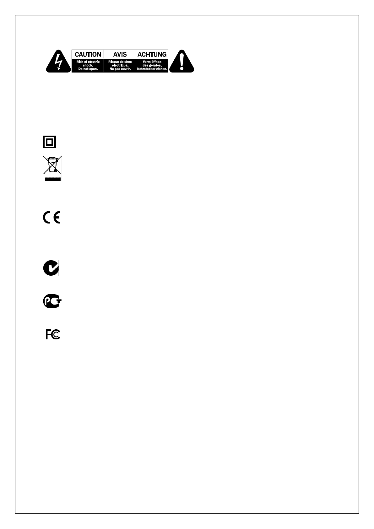
Important safety instructions
8
The lightning flash with the arrowhead symbol within an equilateral triangle is intended to alert the
user to the presence of un-insulated ‘dangerous voltage’ within the product’s enclosure that may be of
sufficient magnitude to constitute a risk of electric shock to persons.
The exclamation point within an equilateral triangle is intended to alert the user to the presence of
important operating and maintenance instructions in the service literature relevant to this appliance.
The symbol on this product indicates that it is of CLASS II (double insulated) construction.
WEEE symbol
The crossed-out wheeled bin is the European Union symbol for indicating separate
collection for electrical and electronic equipment. This product contains electrical and
electronic equipment which should be reused, recycled or recovered and should not be
disposed of with unsorted regular waste. Please return the unit or contact the authorised dealer from
whom you purchased this product for more information.
CE mark
This product complies with European Low Voltage (2006/95/EC) and Electromagnetic
Compatibility (89/336/EEC) Directives when used and installed according to this instruction
manual. For continued compliance only Cambridge Audio accessories should be used with this
product and servicing must be referred to qualified service personnel.
C-Tick mark
This product meets the Australian Communications Authority’s Radio communications and
EMC requirements.
Ross Test Stamp
This product meets Russian electronic safety approvals.
FCC regulations
NOTE: THE MANUFACTURER IS NOT RESPONSIBLE FOR ANY RADIO OR TV
INTERFERENCE CAUSED BY UNAUTHORIZED MODIFICATIONS TO THIS
EQUIPMENT. SUCH MODIFICATIONS COULD VOID THE USER AUTHORITY TO
OPERATE THE EQUIPMENT.
This equipment has been tested and found to comply with the limits for a Class B digital device,
pursuant to Part 15 of the FCC Rules. These limits are designed to provide reasonable protection
against harmful interference in a residential installation. This equipment generates, uses and can
radiate radio frequency energy and, if not installed and used in accordance with the instructions, may
cause harmful interference to radio communications. However, there is no guarantee that interference
will not occur in a particular installation.
If this equipment does cause harmful interference to radio or television reception, which can be
determined by turning the equipment off and on, the user is encouraged to try to correct the
interference by one or more of the following measures
– Re-orient or relocate the receiving antenna.
– Increase the separation between the equipment and receiver.
– Connect the equipment into an outlet on a circuit different from that to which the receiver is
connected
– Consult the dealer or an experienced radio/TV technician for help.

Important safety instructions
9
Ventilation
IMPORTANT – The unit will become hot when in use. Do not place anything on top of the unit. Do not
place in an enclosed area such as a bookcase or in a cabinet without sufficient ventilation.
Ensure that small objects do not fall through any ventilation grille. If this happens, switch off
immediately, disconnect from the mains supply and contact your dealer for advice.
Positioning
Choose the installation location carefully. Avoid placing it in direct sunlight or close to a source of
heat. No naked flame sources, such as lighted candles, should be placed on the unit. Also avoid
locations subject to vibration and excessive dust, cold or moisture. The unit can be used in a
moderate climate.
This unit must be installed on a sturdy, level surface. Do not place in a sealed area such as a
bookcase or in a cabinet. Do not place the unit on an unstable surface or shelf. The unit may fall,
causing serious injury to a child or adult as well as serious damage to the product. Do not place other
equipment on top of the unit.
Due to stray magnetic fields, turntables or CRT TVs should not be located nearby due to possible
interference.
Electronic audio components have a running in period of around a week (if used several hours per
day). This will allow the new components to settle down and the sonic properties will improve over this
time.
Power sources
The unit should be operated only from the type of power source indicated on the marking label. If you
are not sure of the type of power-supply to your home, consult your product dealer or local power
company.
This unit has been designed to be left in Standby mode when not in use, this will increase the life of
the unit (this is true with all electronic equipment). To turn the unit off, switch off at the rear panel. If
you do not intend to use this unit for a long period of time, unplug it from the mains socket.
Overloading
Do not overload wall outlets or extension cords as this can result in a risk of fire or electric shock.
Overloaded AC outlets, extension cords, frayed power cords, damaged or cracked wire insulation and
broken plugs are dangerous. They may result in a shock or fire hazard.
Be sure to insert each power cord securely. To prevent hum and noise, do not bundle the
interconnect leads with the power cord or speaker leads.
Cleaning
To clean the unit, wipe its case with a dry, lint-free cloth. Do not use any cleaning fluids containing
alcohol, ammonia or abrasives. Do not spray an aerosol at or near the unit.
Battery disposal
Batteries may contains substances harmful to the environment. Please dispose of any discharged
batteries with due consideration and in consideration with local environmental/electronic recycling
guidelines.

Important safety instructions
10
Loudspeakers
Before making any connections to loudspeakers, make sure all power is turned off and only use
suitable interconnects.
Servicing
These units are not user serviceable. Never attempt to repair, disassemble or reconstruct the unit if
there seems to be a problem.
A serious electric shock could result if this precautionary measure is ignored. In the event of a
problem or failure, please contact your dealer.
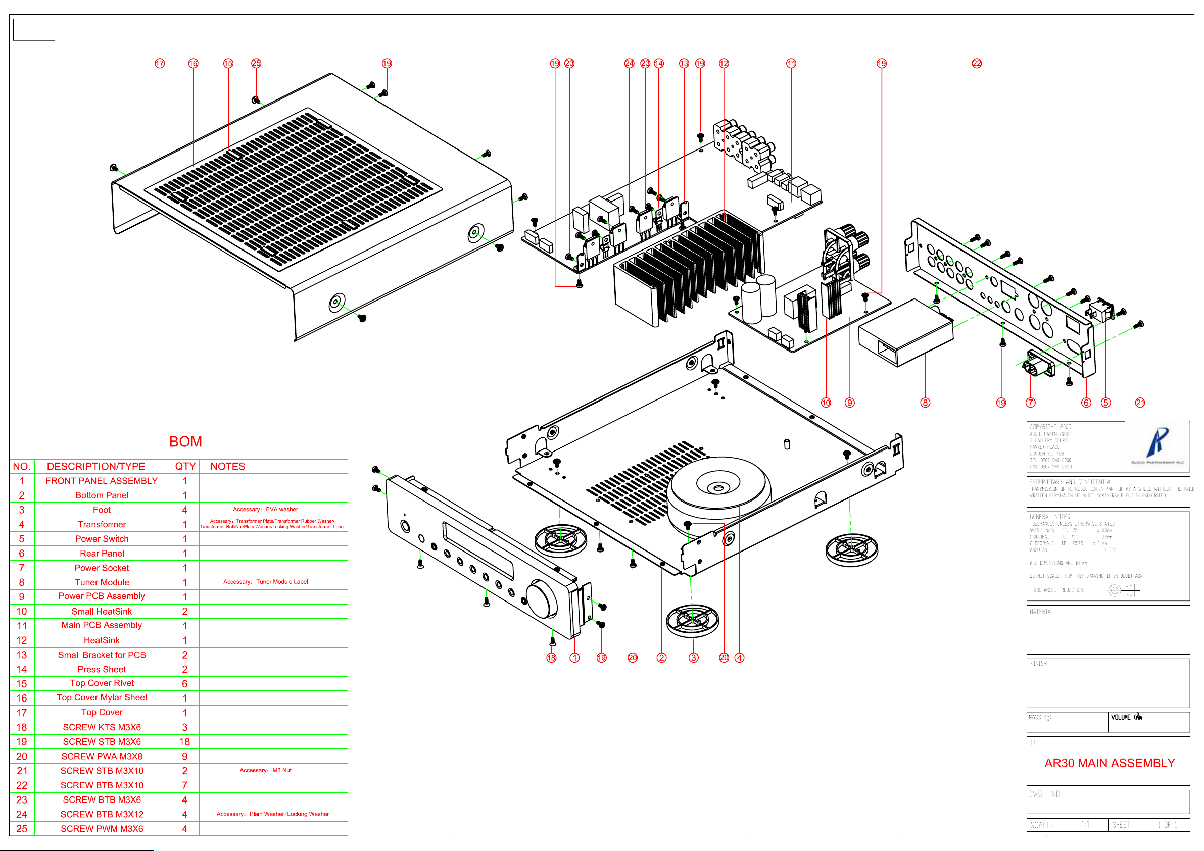
Cambridge Audio Sonata AR30 v2
Exploded Diagram
12
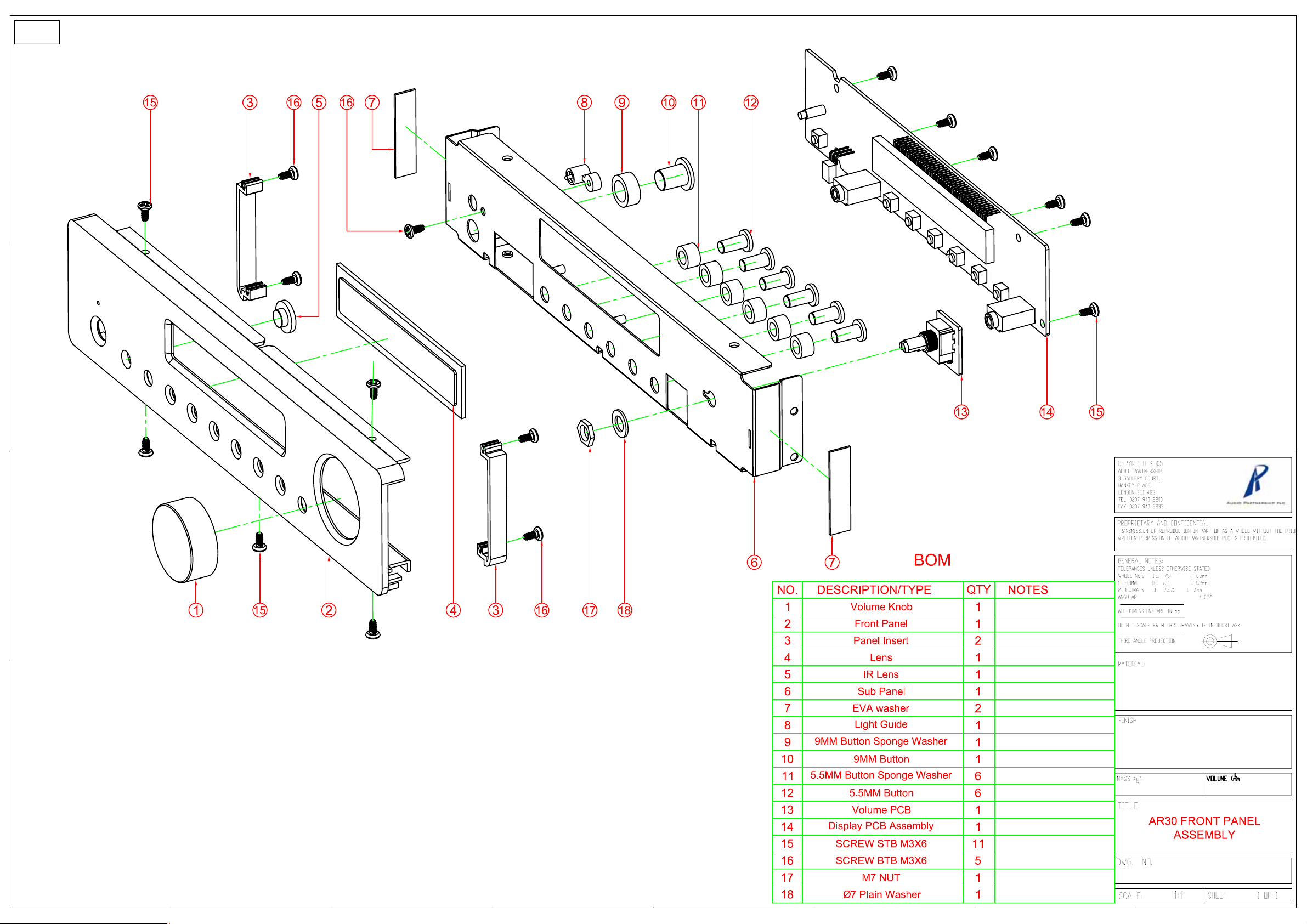
Cambridge Audio Sonata AR30 v2
Front Panel Assembly

Drawingre
f
5
5
2
1
8
6
7
k
)
1
1
2
+
y
g
g
6
2
3
7
3
4
9
3
5
8
7
1
4
1
6
Sonata AR30v2 Parts Table
notshown
1
1
JK1/JK2 071‐000422‐0404RHeadphoneJackPJ‐329PCS2.000000JK1,JK
U1 037‐502595‐3304RIC[ROHS]LM2595T‐ADJ[TO..220]5pinU
Q8 033‐548050‐D204RTransistorS8050,TO92‐EBCT002100017‐RQ
Q6 **2033‐548550‐TransistorC8550TO‐92Q
Q7 **2033‐909014‐C204RTransistorC9014[TO‐92]β300T002100006‐RQ
FMant 088‐AR3001‐W003RAntenna[ROHS]FM PZ288
AMant **2088‐AR3002‐W003RAntenna[ROHS]AM PZ289
Tuner
6
7
notshown 071‐00IPOD‐iPodDoc
4
4
(frontpaneldiagram)item14
partofitem14
RM201 041‐611838‐0313RIRReceiverModule[ROHS]BRM‐VS‐1838E006100004‐RRM20
(frontpaneldiagram)item13 050‐031150‐8143REncoderSwitchEC110101R2D‐HA1‐015semiaxis,BMQ20
9
10 AR30v2AMPPCBcompleteass
BNC1 071‐212461‐1404R4RCASocketRCA‐413GoldenPlatin
BNC2 071‐212461‐1414R6RCASocketRCA‐613GoldenPlatin
Q312/412 033‐211693‐Transistor[ROHS]2SA1693T03‐BQ312,Q41
Q313/413 033‐234466‐Transistor[ROHS]2SC4466T03‐BQ313,Q41
Q307/407 2033‐265551‐C204RTransistor2N5551,TO92‐EBC(β80‐250)T002100010‐RQ307,Q40
RelayRY1 007‐24Q05F‐Relay[ROHS]24VDC5A 4pinRY1 PZ312
U3 038‐204560‐ChipIC[ROHS]JRC4560[SOP8Z]A001000051‐RU
U4 2038‐301258‐ChipIC[ROHS]R5F21258SNFP[LQP52]U
U9 2038‐501117‐ChipIC[ROHS]LD1117S33SOT‐223[3.3V]U
U13 2038‐614053‐ChipIC[ROHS]4053[SOP16]PCS1.000000U1
U2/5 2038‐674141‐ChipIC[ROHS]74HCT14[SOP14Z]U2,U
U8 2038‐67WH08‐0004RChipIC[ROHS]TC7WH08FU[SSOP8]U
U7 038‐074810‐ChipIC[ROHS]STC810M[SOT‐23]4.38VPCS1.000000U
U201 2038‐074H1G‐0004RChipIC[ROHS]74HAC1G14GW[SOT353]U20
U14 2038‐202257‐ChipIC[ROHS]PT2257‐S[SOP8Z]U1
U1 2038‐202319‐ChipIC[ROHS]PT2319[SOP36Z]U
U6 2038‐203130‐ChipIC[ROHS]FM3130[SOP8Z]U
ServicepartsAR30v2 APpart
980‐AR3001‐A01RAR/DR30 RemoteControl
300‐AR3001‐M102RFrontPanelAluminiumAR30‐MB081013A3,,S‐AR30‐FQ080624A
300‐AR3001‐M002RFrontPanelAluminiumAR30‐MB081013A3,S‐AR30‐FQ080624A
912‐YST982‐A01RAR30tunerModuleYST982‐D2E3‐R
209‐AR3001‐P104RFoot[ROHS]A/AR/DR30‐AP126522,silver
209‐AR3001‐P004RFoot[ROHS]A/AR/DR30‐AP126522,black
001‐AR3001‐C0021RTransformer TC‐AR/DR30‐A081107A6 230VACFOREU
001‐AR3001‐C1021RTransformerTC‐AR/DR30‐B081107A3110VforCU
904‐AR3001‐2081111A02RAR/DR30DisplayBoard AssemblyPCS
040‐1271NKG001RAR3/DR30 VFD [ROHS]10‐BT‐271NK(FUTABA
071‐351900‐2404R4RCASocketWP4‐10WVerticalSPK
903‐AR3001‐A01RAR30v2/DR30
071‐158102‐2004RiPodSocketC8102‐09YKSB00RBNC
034‐595401‐0204RSMDTransistor[ROHS]2N5401[TO‐23] PZ310
PowersupplyBoardAssembly
silver
black
PY1478
PZ281
PZ282
PZ283
PZ284
PZ285
PZ286
PZ287
PZ290
PZ295
PZ296
PZ132
PZ297
PZ298
PZ299
PZ300
PZ301
PZ302
PZ303
PZ569
PZ570
PZ305
PZ306
PZ307
PZ308
PZ309
PZ311
PZ313
PZ314
PZ315
PZ316
PZ317
PZ318
PZ319
PZ320
PZ321
PZ322
PZ323
 Loading...