

Cambridge Audio 540R V2.0 Service Manual
Gallery Court Hankey Place London SE1 4BB UK
Tel: +44 (0)20 7940 2200 Fax: +44 (0)20 7940 2233
540R V2.0
First Issue Date: 29th June 2006
Second Issue Date: 9th October 2006
SERVICE MANUAL
SPECIFICATIONS:
Audio Section
Power Output Front 100W RMSx2(8ohm, 1% THD)
Centre 100W RMS (8 ohm, 1% THD)
Surr. (L/R) 100W RMS x 2 (8 ohm, 1% THD)
Surr. Back 100W RMS (8 ohm, 1% THD)
Output Impedance Front (L/R) 8 ohm
Centre 8 ohm
Surr. (L/R) 8 ohm
Surr. Back 8 ohm
THD (unweighted) less than 0.05%
Line Input
Input Impedances 150mV/47k
Frequency Response 20Hz~25KHz+0.5/-1dB
Tone Control Range Bass ± 6dB - Treble ± 6dB
S/N ratio (ref 1W/8 Ohm) 75dB
Subwoofer Output
Rated Output/Impedance 150mV/10k
Frequency Response 10Hz~300Hz+3dB
FM Tuner Section
Frequency Range 87.5~108MHz
Sensitivity 14dB (5uV)
Antenna Terminal 75 ohm (unbalanced)
AM Tuner Section
Frequency Range 522~1629kHz, 9kHz step
Sensitivity 68 dB/M
Signal to Noise Range 30 dB
Antenna Loop Antenna
Power Requirement AC230V~50Hz
Max Power Consumption 615 Watts
Dimensions (W x D x H) 350 x 430 x 150
Weight 15.8kg
AP19914/3
Third Issue Date: 02nd February 2007
1

540R V2.0 SERVICE MANUAL
TABLE OF CONTENTS
Front Panel Information
3
Remote Control
4
Remote Control Function
5
Rear Panel Information
6
Exploded Diagram
7
Exploded Diagram Parts List
8-9
PCB Interconnect Diagram
10
Decoder PCB Schematic
11-13
Decoder PCB Board Layout
14-15
Main Board – Power Supply PCB Schematic
16
Power Output & Speaker Protection
17
Main/Video Out/Speaker Connections PCB Board Layout
18
OSD PCB Schematic
19
OSD / Co-axial in/out / Connect Board B / Control Bus)
20-21
YUV PCB Schematic
22
YUV PCB Layout
23
Input / Outputs PCB Schematic
24
Display Board PCB Schematic
25
Display / Volume / AV3 PCB Layout
26
Co-axial in/out / Control Bus PCB Schematic
27
Connect Board B
28
Connect Down PCB
29-30
AC Input / Relay / Headphones PCB Schematic
31
AC Relay / Headphones PCB Layout
32
Bill of Materials
33-38
IC Pin Layout Details
39-40
Serviceable Parts List
41
2
Cambridge Azur 540R V2.0 AV Receiver
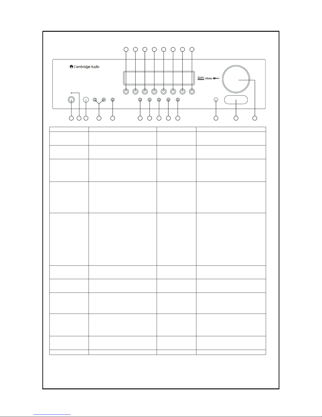
Front Panel Information
1 2 3 4 5 6 7 8 9 10 11 12 13
14 15 16 17 18 19 20 21
Standby/On
Phones
- Tuning +
Mode/Store
Stereo Dolby DigitalEX
DTS ES
Pro Logic /
Neo 6
DSP
Mode
Input
Mode
Video Left Right
Video 3 Inpu ts
Volum e
azur 540R
AV Re ceive r
DVD
Video 1 Video 2 Video 3
Tun er FM /A M
Tape/MD/CDR
CD/Aux
6.1 Dire ct
NO. & NAME DESCRIPTION NO. & NAME DESCRIPTION
1. Standby /On
The power amplifier is in standby mode,
indicated by the stand by indicator.
12. V ideo 3 Inputs
Input for VCR, Video Camera Recorder,
etc. contains one video input and
Analog Left and Right inputs.
2. Standby Indicator 13. Volume
Rotate this knob clockwise or
counterclockwise, the master volume will
be increased or decreased.
3. Phones
Jack for the stereo headphones.
14. DVD
When the coaxial /optical output terminal
of a DVD player is connected to the
DVD COAXIAL/OPTICAL IN terminal
of this unit (5/6 rear panel), press this
button to activate this function.
4.Tuning+/-
Tuner frequency or preset stations up &
down.
15. V ideo 1
When the line output of an external
player is connected to the AV 1 terminal
of this unit (6/rear panel), or when the
digital /optical output of another player is
connected to the OPTICAL IN of this
unit (6/ rear panel), press this button to
activate this function.
5.Mode/Store
Press this button once to select Auto
tuning mode; press it the second time to
select the Manual tuning mode; press it
the third time to select the Preset tuning
mode, then by pressing the Tuning +/button to select a preset station; pressing
and holding this button (in any of the
modes above) for 5 seconds brings up
the “MEM” icon and display the next
available preset for storing the current
frequency.
16. V ideo 2
When the line output of an external
player is connected to the AV 2 terminal
of this unit (6/rear panel), or when the
digital /optical output of another player is
connected to the OPTICAL IN of this
unit (6/ rear panel), press this button to
activate this function.
6.Stereo
With the unit in the STEREO mode,
only front left and front right speakers
and Subwoofer are working.
17. V ideo 3
When you want to use Video 3 inputs,
pressing this button to activate this
function.
7.Dolby Digital EX
DTS ES
Digital Surround Mode
18. T uner FM/AM
8.Dolby
Pro Logic II
/NEO 6
Surround modes for analog sources
19. T ape/MD/CDR
Press this button when operating the tape
deck.
9.DSP Mode
Press this button to choose one of the
following surround modes: THEATER,
HALL, PASSTHRU, MOVIE, MUSIC
and ROOM.
Analog or digital
20. CD/Aux
When the coaxial output terminal of a
CD player is connected to the CD
COAXIAL IN terminal of this unit (5/
rear panel), press this button to activate
this function.
10.Input Mode
Press this button to select input modes:
ANA, OPT and COAX when using
digital in.
21. 6.1 Dir ect
Press this button to select the 6.1
analogue input.
11. Remote Sensor
To listen to the radio broadcast, press this
button to activate this function, press
again to switch waveband.
3
Cambridge Azur 540R V2.0 AV Receiver
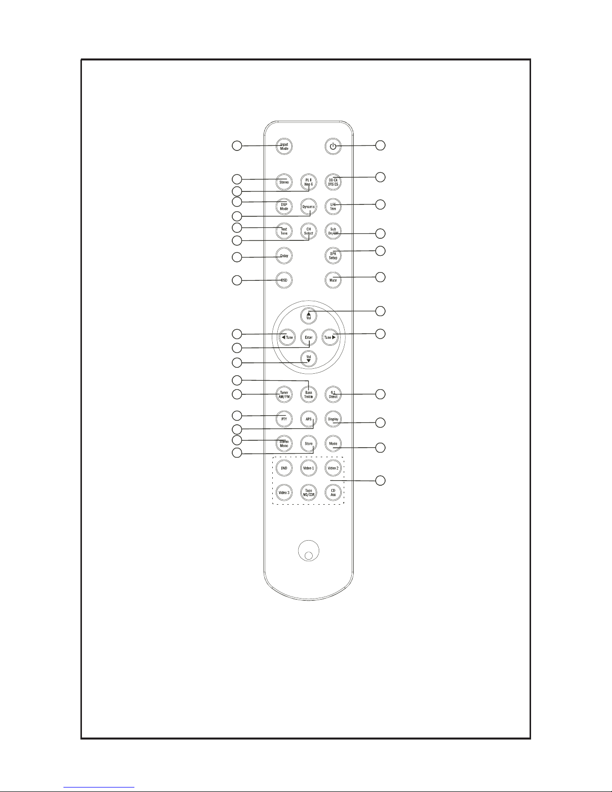
Remote Control
1
5
8
11
13
16
19
23
26
29
21
25
22
18
17
12
9
6
3
2
10
30
7
20
4
14
15
24
28
27
4

NO. & NAME DESCR I PT ION NO. & NA ME DESCR I PT ION
1.
Power On/Standby
Pressthisbuttontoturnthisunitonor
off .
16.
/Volumeup
-Directionbutton.
- P ress thes e buttons to i ncr ease the
volume.
2.
Input Mode
P ress i t to s elec t:
17.
/Tunedown
- D ir ecti on button.
- T uner f requency down.
3.
St er eo
With this unit in ST ER E O mode, only
FrontLeft& FrontRightspeakersand
Woof er hav e output.
18.
Enter
Pr ess thi s button w hen y ou w ant to enter
the O SD setup menu.
4.
PL II /NEO 6
When receiving Analog/digital PCM
signals.
19.
/Tuneup
-Directionbutton.
- T uner f requency up.
5.
DDEX /DTSES
For digital surround signals
20.
/ V ol ume d own
-Directionbutton.
- P ress thes e buttons to dec rease the
volume.
6.
DSP MODE
Pr ess thi s button to choos e one of the
following surround modes: THEATER ,
HAL L, PASSTHRU, MOVIE, MUSIC
and ROOM.
21.
Tuner AM/FM
Pr ess thi s button to al terna te between F M
and A M.
7.
Dynamic
P ress thi s button r epeatedl y to r each y our
desired compression dynamic range.
22.
B ass/ Treble
Pr ess thi s button f or B a ss / T r eb le
adj ustment, then pr ess V ol up and V ol
dow n to a djust the l evel .
8.
LFE Trim
Under the Pro L ogic 5.1CH or DT S
5.1C H mode, press this button and adjust
thevolumetosettheLowFrequency
output l evel
23.
6.1 Dir ect
Pr ess thi s button to s elec t the 6 .1 ana logue
input.
9.
TestTone
T o bal anc e s peak ers i n D ol by D i gi tal or
Dolby ProLogic mode.
24.
PTY
I n F M state, pr ess thi s button, the cur rent
program type appears onthe display, using
T uni ng +/- to s elec t the pr ogram t ype y ou
desi r e.
10.
CH Select
S elec t cha nnels by pus hing thi s button,
thenusevolumekey tobalancespeakers
25.
APS
Allocates and memorizes radiostations
automatical ly.
11.
Sub On/Off
Pr ess thi s button to turn on/of f the output
of s ubwoof er.
26.
Display
W ith R D S , pr ess thi s button r epeatedly to
hav e P S ( progr am name) or C T (c urrent
ti me).
12.
Delay
Pr ess thi s button to set the del ay ti me f or
the Dolby digital/Dolby Pro Logic modes.
27.
St er eo / M on o
Pr ess thi s button to al terna te between
S tereo and M ono mode w hen l i sten to F M
bro adcas t.
13.
SPK Setup
Under PRO LOGIC II or Digital state, it
can cha nge the des ir ed S peak er S etti ng
shownonthedisplay.
28.
Store
Pr essi ng thi s button to s tore the c urrent
frequency.
14.
OSD
Pr ess thi s button to ac cess the A V
Receiver configuration settings by using
the O S D menus .
29.
Mode
Pr essi ng thi s button to s elec t A uto /M anual
tuni ng mode and P reset mode.
15.
Mute
Pr ess thi s button to mute the sound, push
again to cancel the mute f unction.
30.
I n put S el ect or
Pr ess the c orr esponding button ac cordi ng
to y our desi red s elec tion.
Cambridge Audio Azur 540R V2.0 AV Receiver
Remote Control Function
Digital or Analogmode.
5
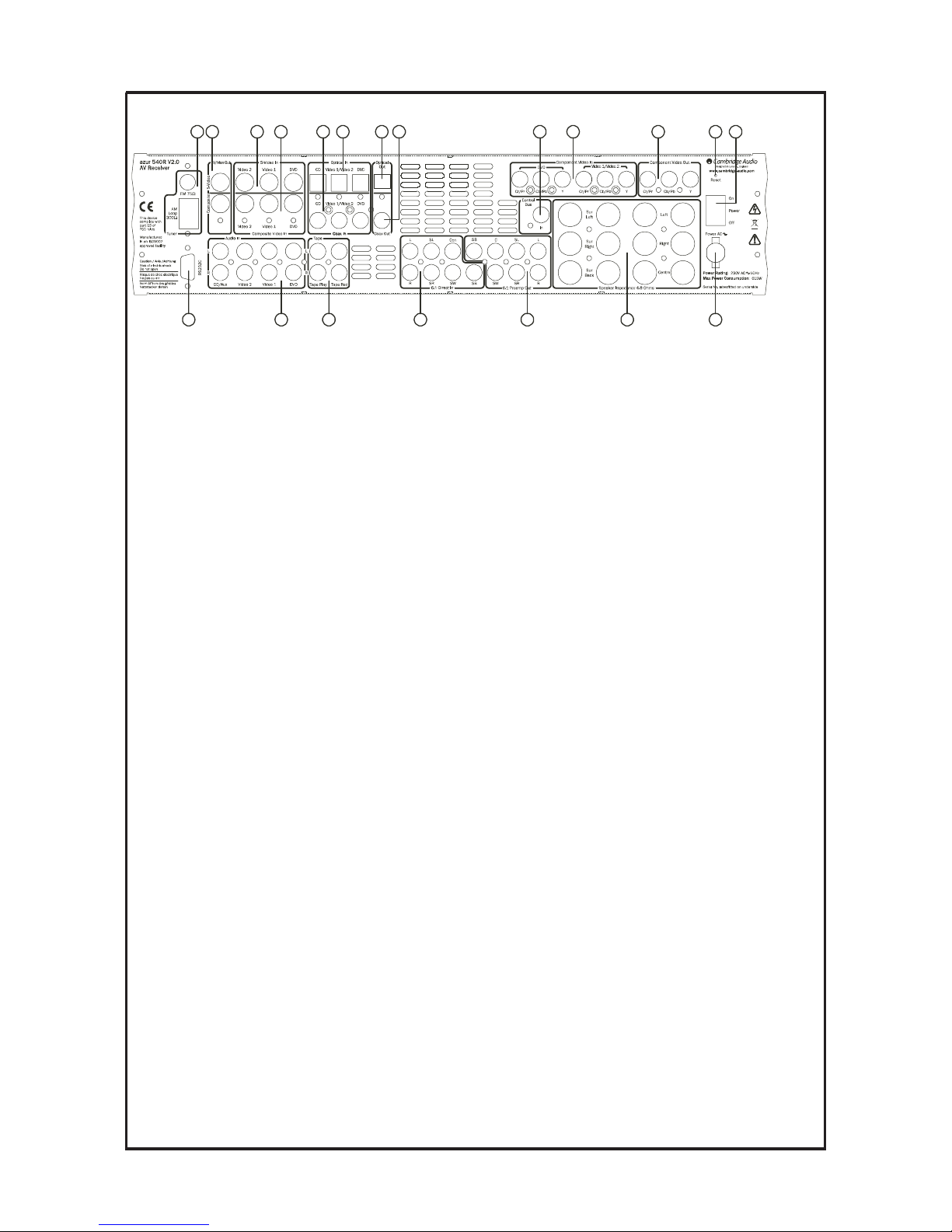
Cambridge Azur 540R V2.0 AV Receiver
Rear Panel Information
1 2 3 4 5 6 87 10 11 12 13
141516171819 18
9
1. FM / AM antenna
2. TV /Mon Out
S-V ideo out ….. using the S-Video cable to connect this terminal to the corresponding terminal on the TV set.
C omposite Video out ….. using the RCA cable to connect this terminal to the corresponding terminal on the TV
set.
3. S-V ideo in
V ideo 1 / Video 2 ….. connect to the corresponding output terminals of a VCR.
DVD ….. connect to the corresponding line output terminal of a DVD player.
4. C ompositeV ideo in
V ideo 1 / Video 2 ….. connect to the corresponding output terminals of a VCR.
DVD ….. connect to the corresponding line output terminal of a DVD player.
5. C oax in
CD ….. digital audio input to the digital output of a CD player.
V ideo 1 / Video 2 ….. digital audio input to the digital output of a VCR.
DVD ….. digital audio input to the digital output of a DVD player.
6. Optical in
CD ….. optical audio input to the optical output of a CD player.
V ideo 1 / Video 2 ….. optical audio input to the optical output of a VCR.
DVD ….. optical audio input to the optical output of a DVD player.
7. Optical Out ….. digital audio output to the digital optical input of another amplifier, external recording device or
decoder.
8. C oax Out ….. digital audio output to the digital coaxial input of another amplifier, external recording device or
decoder.
9. Contr ol Bus terminal …… This terminal is used for our system controlling.
10. C omponentV ideo In
DVD ….. connect to the Cr Cb Y terminal of a DVD player.
V ideo 1 / Video 2 ….. connect to the Cr Cb Y terminal of external players.
11. C omponentV ideo Out ….. connect to the Cr Cb Y terminal on the TV set.
12. R eset ….. this is used to reset the whole system (including the memories set).
13. Power On / off ….. pressing this switch to turn on /off this unit.
14. Power AC ….. connect to the AC socket.
15. Speaker terminals ….. connect to the external speakers with 4~8 impedance.
16. 6.1 Pr eamp Out ….. connect to the 7 channel input terminals of another amplifier.
17. 6.1 D irect In ….. connect to the 7 channel output terminals of another player.
18. A udio In
Tape Rec ….. connect to the line input terminals on the Tape Deck.
Tape Play ….. connect to the line output terminals on the Tape Deck.
DVD ….. connect to the line output terminal of a DVD player.
V ideo 1 / Video 2 ….. connect to the line output terminals of external players.
CD / Aux ….. connect to the line output terminal of a CD player.
19. R S232C ……. This terminal is used for software upgrade.
6
Cambridge Audio Azur 540R V2.0 AV Receiver
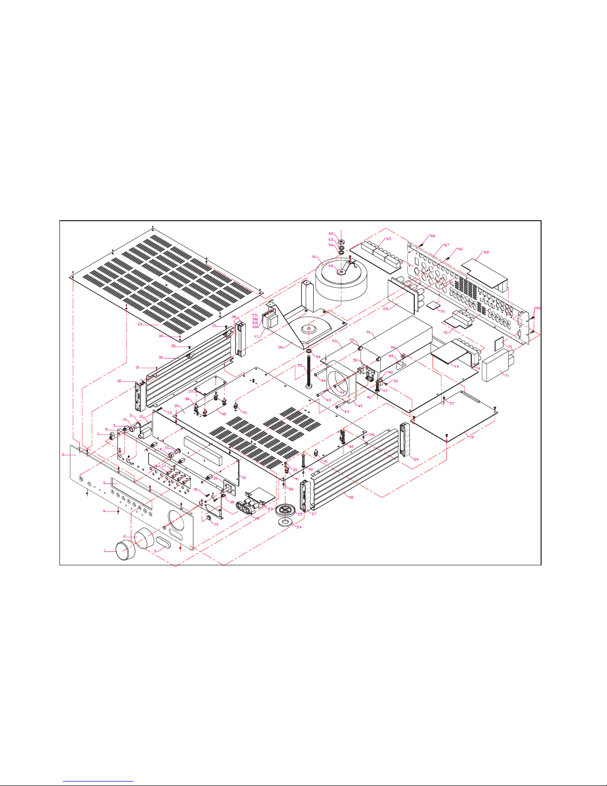
Exploded Diagram
To enhance viewing, please print to A3 7
Cambridge Audio Azur 540R V2 AV Receiver
Spare Parts Exploded Diagram
krameR.ytQnoitpircseD.ONtraP.leS
1 6531 1010 0011 VOLUMN KNOB AL SKIN 1
1BONKNMULOVPMA0000040113372
1revoc3VA1900001113973
86X0.3BTBWERCS00006
00341054
1SNELYALPSID0800010113475
1LENAPLA1220010113066
1EDIUGTHGILPMA0000030113477
8 5331 1010 0000 SCALEBOARD 1
01NMULOCBCP00000201
13979
10 7631 1010 0000 MR CONTROL BOX BUTTON CUSHION 1
11 7331 1010 0011 MR CONTROL BOX BUTTON 1
12 0554 0117 1001 PHONE PCB 1
13 5011 3014 1000 SCREW BTB3.0X14 10
14 7631 1020 0000 7MM TAC SWITCH BUTTON CUSHION 8
15 7331 1020 0011 7MM TAC SWITCH BUTTON 8
16 7631 1030 0000 4MM TAC SWITCH BUTTON CUSHION 8
17 7331 1030 0011 4MM TAC SWITCH BUTTON 8
514X0.3BTBWERCS00014003110581
1SNELRI00000201134791
20 0054 1030 0004 VOLUMN PCB 1
21 0054 1030 0004 DISPLAY PCB 1
1NOITAROCED11000101139722
23 0054 1083 2005 AV3 PCB 1
4DAPTOOF1000060113
9742
4TOOF11000501139752
48X0.3MB00018003210562
27 7531 1040 0000 540R front support right assy 1
1)THGIR(REVOCEDIS11000201134682
29 7531 1050 0000 540R rear support right assy 1
30 7531 1020 0000 540R front support left assy 1
88X6.2BTBWERCS000080624
10513
1)TFEL(REVOCEDIS11000101134623
1REVOCPOT11000101131633
88X6.2MBWERCS00018062810543
646X0.3BTBWERCS0
0016003110553
1yssatfeltroppusraerR04500000301135763
37 0054 0110 1001 FUSE PCB 1
401=HNS01-SBC00000000117883
1REVOCMOTTOB1100010113
2693
1CVPBCP01050040807704
76=HNS6-SBC00000006017814
204=H283-TDDK00000000437824
242=LTLOB00000301139534
2
23=LTLOB00000101139544
1NAF13233152201954
2)3Hx4Dx01D(HSAW00000701139764
103=HNS03-SBC00000000317874
8
Cambridge Audio Azur 540R V2 AV Receiver
Spare Parts Exploded Diagram
2TEKCARBNAF00000301133584
1TEKCARBBCPEDOCED00000601133594
2TEKCARBKNISTAEH00000201133505
1KNISTAEH000001
01131515
2NMULOCKNISTAEH00000201139525
53 0054 1003 2005 MAIN PCB 1
54 5040 8000 0001 WASH
28
1TLOB04000808510555
56 5331 1050 0011 TRANSFORMER BRACKET 1
428X0.3BTBWERCS00018003110575
58 5020 3006 0360 NUT
22.3
59 5040 0300 0000 SPRING WASHER
20.3
60 5030 0800 3210 WASH
3.2 x 8.0 x 1.0mm 2
1REMROFSNART00005101000416
62 5020 8012 0201 NUT
18
13MREHSAWGNIRPS10000003040536
1LAERUTAREPMET00000501139546
65 0054 1140 1002 YUV PCB 1
248x0.3APWERCS0008003310566
1REVOCKCAB1110
0301133676
68 0054 1241 1006 OSD PCB 1
69 0054 1233 2005 OUTPUT PCB 1
70 0054 1381 2006 COAX PCB 1
1XOBRENUT10003000008917
72 0054 1280 1005 DECODE PCB 1
73 0054 1321 3006 CONNECT PCB(T) 1
74 0054 1321 0003 CONNECT PCB(B) 1
1BCP232S00003229450057
76 0054 1221 4006 CONTROL PCB 1
1REMROFSNARTSBTS00015531000477
9
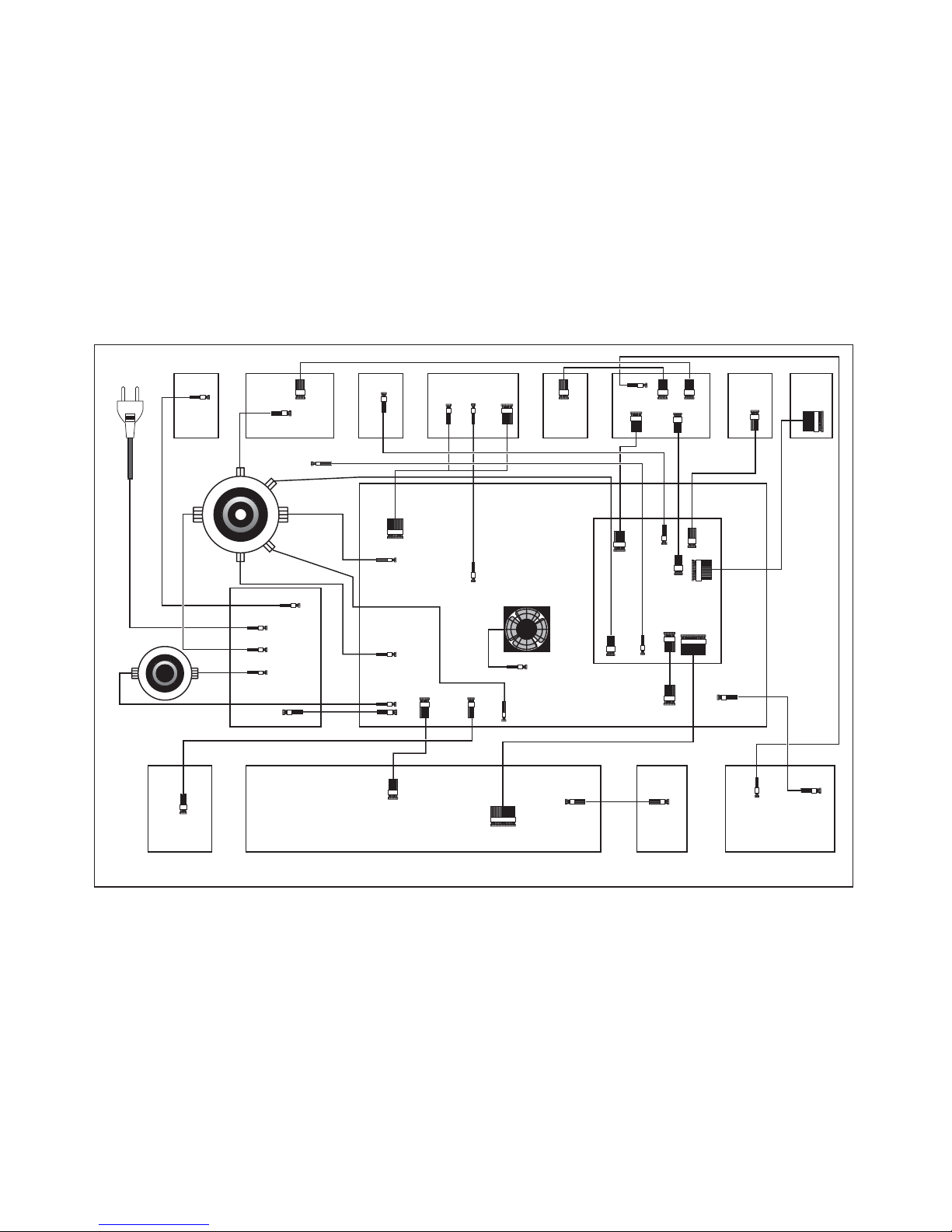
Cambridge Audio Azur 540R V2 AV Receiver
PCB Interconnect Diagram
Power Cordin
2P
CN3
FAN
2P
CN2
2P
CN3
2P
CN4
2P
CN1
3P
CN5
3P
CN11
2P
CN9
2P
CN8
2P
CN6
2P
CN22
3P
CN21
3P3P
3P
CN2
2P
CN4
2P
CN1
2P
CN23
3P
CN7
3P
CN7
3P
4P
J200
4P
CN17
2P
CN1
6P
CN5
6P
J1
16P
J2
16P
CN5
7P
J1
7P
CN10
5P
J2
5P
CN2
5P
13P
CN4
13P
CN1
5P
CN3
5P
CN5
7P
CN6
7P
CN1
6P
CN36PCN2
6P
CN5
6P
2P
3P
7P
CN20
10P
CN16
2P
CN4
2P
HEAT-VARIABLE
RESISTOR
Transformer
Transformer
Earphone
Board
Display Board
AV3 Board
Volume
Board
Main Board
Decoder Board
Relay Board
YUV
Board
Remote
Board
Speaker Board
Switch
Board
Coaxial
Board
OSD Board
Upgrade
Board
Tuning
Board
10
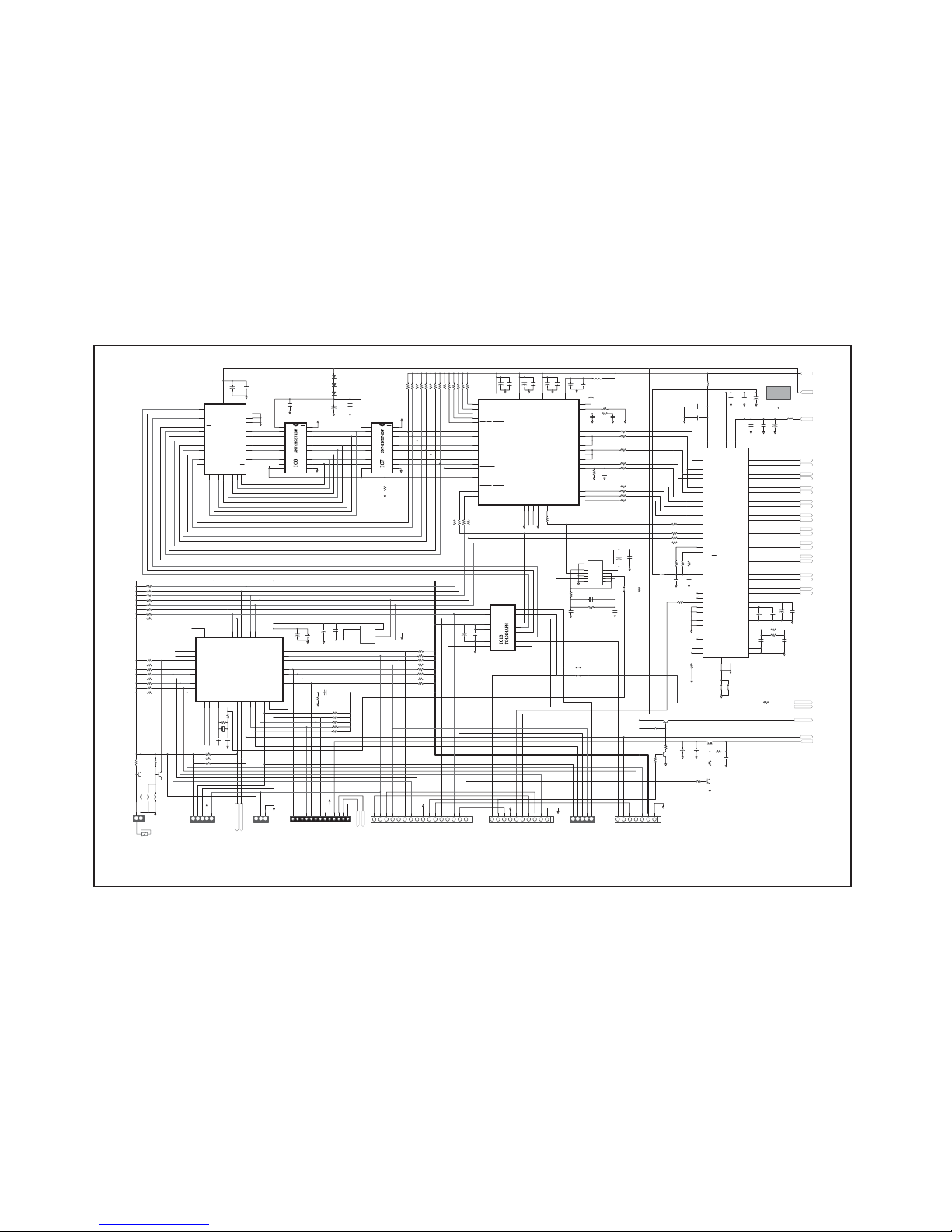
Cambridge Audio Azur 540R V2.0 AV Receiver
Decoder PCB Schematic (1of 3)
C29
104
C30
104
C28
104
+
C2
10/16
+
C1
10/16
9'
R59
33K
R13 10K
R1
3.3K
R1110K
R53
4.7K
R554.7K
R12
10K
R54
4.7K
R564.7K
C31
104
C32
104
C33
104
C34
104
C35
104
C84
471
+
C70
2.2/50
+
C71
2.2/50
+
C72
2.2/50
+
C73
2.2/50
+
C75
47/25
DGND
L1
FB
R100
33
R103 33
R93 33
R101 33
R102
33
R60
47K
R9933
R91
33
R92
33
R9633
R9833
R910K
R710K
R4
10K
R6
10K
R10
10K
R810K
R510K
R3
10K
C89
100P
OE
1
D1
2
D2
3
D3
4
D4
5
D5
6
D6
7
D7
8
D8
9
GND10CLK
11
Q8
12
Q7
13
Q6
14
Q5
15
Q4
16
Q3
17
Q2
18
Q1
19
VCC
20
,&
61+&':
Q0
13
Q1
14
Q2
15
Q3
17
Q4
18
Q5
19
Q6
20
Q7
21
OE
24
A75A66A57A48A39A210A111A0
12
A8
27
A9
26
A10
23
A11
25
A12
4
A13
28
A14
29
CE
22
A15
3
A16
2
A17
30
VCC
32
VPP
1
PGM
31
GND
16
IC5
AT27C020
OE
1
D1
2
D2
3
D3
4
D4
5
D5
6
D6
7
D7
8
D8
9
GND
10
CLK
11
Q8
12
Q7
13
Q6
14
Q5
15
Q4
16
Q3
17
Q2
18
Q1
19
VCC
20
,&
61+&':
DGND
DGND
DGND
DGND
DGND
DGND
DGND
DGND DGND DGND
DGND
DGND
DGND AGND
R90
33
DGND
DGND
DNU
1
P1.0
2
P1.1
3
P1.2
4
P1.3
5
P1.4
6
P1.5
7
P1.6
8
P1.7
9
RESET
10
P3.011NC12P3.113P3.214P3.315P3.416P3.517P3.618P3.719XTAL120XTAL221GND22GND
23
P2.0
24
P2.1
25
P2.2
26
P2.3
27
P2.4
28
P2.5
29
P2.6
30
P2.7
31
PSEN#
32
ALE/PROG#
33
DNU
34
EA#35P0.736P0.637P0.538P0.439P0.340P0.241P0.142P0.0
43
VCC
44
IC11
SM5964C40J(PLCC44)
R31 10K
R30 10K
R29 10K
R28 10K
R27 10K
R26 10K
R25 10K
R24 10K
R32
10K
C106
del
C105
del
C45
104
C47
104
C46
104
+
C96
100/10
+
C3
10/16
+
C4
10/16
+
C95
100/10
Z2
del
R105
2.4K
R17
10K
R45 10K
R44 10K
R109
del
R111
del
R43 10K
R42 10K
R23 10K
R48 10K
R19 10K
R15 10K
R16 10K
R39
10K
R49
10K
Q2
C3361
R114 220
R115
1%1.5K
R116 1%560
Q1
C3361
R113
1%750
R117 2K
DGND
R18 10K
R14 10K
DGND
DGND
R9733
1
2
3
4 5
6
7
8
IC12
AT24C01
$
$
$
'*1'
6'$
6&/
:3
9&&
DGND
R47 10K
C92
102
C107
563
C43
104
C44
104
+
C97
100/10
+
C74
2.2/50
C38
104
C40
104
+
C94
100/10
C37
104
C39
104
+
C93
100/10
C36
104
L2
FB
R104
33
R94 33
R41
10K
R40 10K
R21
10K
R22
10K
C91
102
L5
FB
LS-
LS+
FR-
FR+
FL-
FL+
SURRR-
SURRR+
SURRL-
SURRL+
RS-
RS+
C-
C+
LEF-
LEF+
AINR+
AINR-
AINL+
AINL-
2.5VD
5VA
IA
1
QA
2
IB
3
QB
4
IC
5
QC6ID
9
IF
13
QF
12
IE
11
QD
8
VCC
14
GND
7
QE
10
IC10
74LVU04D
R2
3.3K
R108
220
C104
30P
C103
30P
C41
104
+
C76
47/25
Z1
12.288MHz
5VD
C90
102
R112 8.2K
R20
10K
DGND1DGND1
B4
B4
B4
3
3
3
AGND
R95 33
DGND1
DGND
DGND
DGND
DGND
3
3
3
3
DGND
3
3
3
237212))
5(027(
9,'(2212))
9)''$7$
9)'&/.
9)'67%
92/%
92/$
'*1'
%
087('(/$<
&.
'$
67
&
78212))
11223344556677889
9
10101111121213
13
16P
1414151516
16
CN5
16P1.0
9
785
78/
$*1'
72781(5
12345678910111213
CN4
13P(1.0)
78&(
78&/.
78'$7$,1
5'6'$7$
78/('
5'6&/.
78'$7$287
1&
1&
R38 10K
DGND1
29
3212))
087('(/$<
087(
3+'(7
'*1'
720$,1%5'
1122334455667
7
7P
J1
7P2.0
&389
5(6(7
9,'(2212))
237212))
$%&
'*1'
237,1
9
11223344556677889
9
10
10
10P
CN6
10P2.0(540R-V27P2.0)
$*1'
AGND
VOL-DATA
DGND
VOL-CLK
R106
2.4K
3
RESET
36
INTREQ_ABOOT
20
SCCLK_A0
7
SCDIO_SCDOUT_PSEL_GPIO9
19
DC
38
DD
37
VD11VD212VD3
23
VA
34
SC
18
SCDIN_A1
6
DGND213DGND12AGND35DGND3
24
EMAD0_DATA0_GPIO0
17
EMAD1_DATA1_GPIO1
16
EMAD2_DATA2_GPIO2
15
EMAD3_DATA3_GPIO3
14
EMAD4_DATA4_GPIO4
11
EMAD5_DATA5_GPIO5
10
EMAD6_DATA6_GPIO6
9
EMAD7_DATA7_GPIO7
8
EXTMEM_GPIO8
21
WR_DS_EMWR_GPIO10
4
RD_R/W_EMOE_GPIO11
5
MCLK
44
SCLK
43
LRCLK
42
AUDATA0
41
AUDATA1
40
AUDATA2
39
XMT958_AUDATA3
3
CMPCLK_SCLKN2
28
STCCLK_SCLKN1
25
LRCLKN1
26
CMPREQ_LRCLKN2
29
CLKSEL
31
FLT2
32
FLT1
33
CMPDAT_RCV958_SDATAN2
27
SDATAN1
22
CLKIN
30
IC8
CS493263-CL
&B$
&B$
&B$
3
221
1
CN1
2P2.5
DGND
R34 10K
R35
10K
R36
10K
R37
10K
DGND1
9'
'9
'9 9' 9'
3
3
3
3
3
3
3
DGND
C48
104
+
C77
47/25
C49
104
Q3
C3361
R50
10K
Q4
A950
TU-L
TU-R
AGND
AGND AGND
AGND
AGND
12V
TU+12V
112233445
5
CN2
5P2.0
R33 10K
DGND
MCU
DSP
MUTE
9
7;'
5;'
'*1'
757*
26'6,1
26'6&/.
26'&6
67%
DGND
Q5
14
Q6
13
Q7
12
Q1
4
Q2
5
Q3
6
Q4
7
Q8
11
QS
9
CS
10
CLK
3
SDA
2
STR
1
OE
15
VDD
16
VSS
8
,&
7&$)1
DGND1
DGND1
DGND1
AGND
AGNDAGND AGND
AOUTA1+
36
AOUTA1-
37
AOUTB1+
35
AOUTB1-
34
AOUTA2+
32
AOUTA2-
33
AOUTB2+
31
AOUTB2-
30
AOUTA3+
28
AOUTA3-
29
AOUTB3+
27
AOUTB3-
26
AOUTA4+
22
AOUTA4-
23
AOUTB4+
21
AOUTB4-
20
MUTEC
38
AINL+
15
AINL-
16
AINR+
14
AINR-
13
VQ
17
FILT+
18
REFGND
19
LPFLT
39
AGND
40
AGND
25
DGND52DGND
5
VLC
6
VD4VD
51
VARX
41
VA
24
RMCK
55
SAI_SCLK
61
SAI_LRCK
60
SAI_SDOUT
54
CX_SCLK
2
CX_LRCK
3
CX_SDOUT
56
CX_SDIN1
1
CX_SDIN2
64
CX_SDIN3
63
CX_SDIN4
62
RESET
12
SCL/CCLK
7
SDA/CDOUT
8
INT
11
AD1/CDIN
9
AD0/CS
10
RXP7_GPO7
42
RXP6_GPO6
43
RXP5_GPO5
44
RXP4_GPO4
45
RXP3_GPO3
46
RXP2_GPO2
47
RXP1_GPO1
48
RXP0
49
TXP
50
VLS
53
OMCK
59
ADCIN2
57
ADCIN1
58
IC9 CS42518-CQ
DA/AD
R46
10K
DGND1
3
3
729,'(2%5'
72237%5'
DGND
'63'$B5(6(7
R118
22K
R107
2.4K
3212))
316:
72',6%5'
D3
4148
D2
4148
D1
4148
MUTE
DGND
DGND
DGND
DGND
C42
104
DVD/DSP
'9''63
6<9'(/
112233445
5
CN3
5P2.0
R110
33
JP1
0
DGND
JP20JP3
0
JP4
del
JP5
0
3816MUTE
R246
10K
R251
22K
Q8
A1131
R249
10K
SUBMUTE
Q9
C3361
R252
10K
DGND
11223
3
CN8
3P2.0
DGND
,5
9
'*1'
12_NC3
12_NC2
12_NC1
11NC34
11NC33
11NC32
11NC12
11NC1
13NC9
R262
220
R263
220
R264
220
R265 330
L6
FB
VIN
3
GND
1
VOUT
2
IC18
LD1117S3.3(SOT-223)
DGND1
To enhance viewing, please print to A3 11
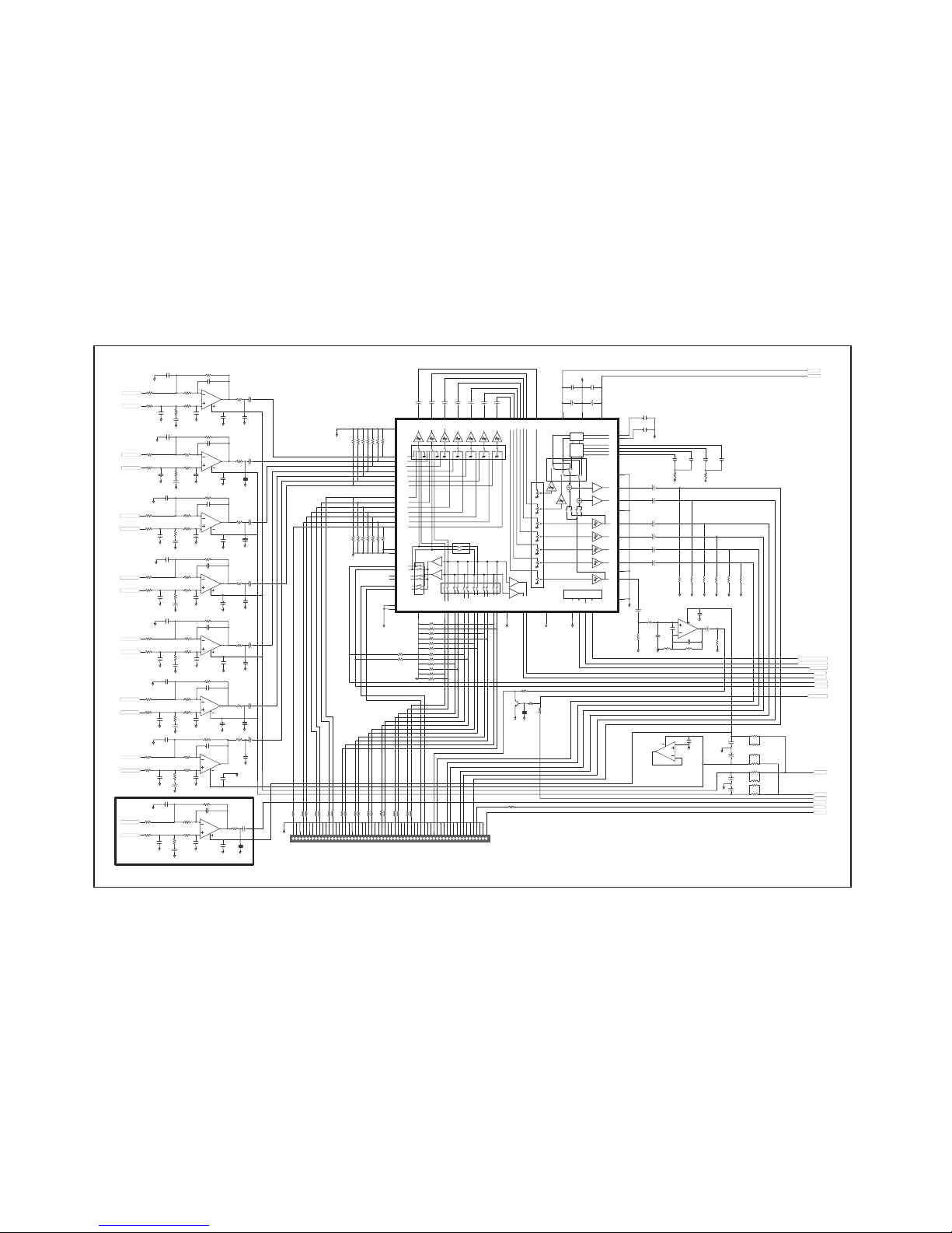
Cambridge Audio Azur 540R V2.0 AV Receiver
Decoder PCB Schematic (2 of 3)
2
3
1
4
IC1A
2068
R201
2.94K
C158
182
R218
6.19K
C183
390
AGND
R177
5.49K
R185
1.65K
R209
887
R193
1.87K
C150
562
AGND
+
C165
22/16
AGND
6
5
7
8
IC1B
2068
R202
2.94K
C159
103
R217
6.19K
C182
473
AGND
R178
5.49K
R186
1.65K
R210
887
R194
1.87K
C151
104
AGND
+
C166
22/16
AGND
2
3
1
4
IC2A
2068
R203
2.94K
C160
182
R221
6.19K
C185
390
AGND
R179
5.49K
R187
1.65K
R211
887
R195
1.87K
C152
562
AGND
+
C168
22/16
AGND
6
5
7
8
IC2B
2068
R204
2.94K
C161
182
R220
6.19K
C184
390
AGND
R180
5.49K
R188
1.65K
R212
887
R196
1.87K
C153
562
AGND
+
C169
22/16
AGND
2
3
1
4
IC3A
2068
R199
2.94K
C156
182
R215
6.19K
C181
390
AGND
R175
5.49K
R183
1.65K
R207
887
R191
1.87K
C148
562
AGND
+
C164
22/16
AGND
6
5
7
8
IC3B
2068
R200
2.94K
C157
182
R216
6.19K
C180
390
AGND
R176
5.49K
R184
1.65K
R208
887
R192
1.87K
C149
562
AGND
+
C167
22/16
AGND
2
3
1
4
IC4A
2068
R206
2.94K
C163
182
R219
6.19K
C187
390
AGND
R182
5.49K
R190
1.65K
R214
887
R198
1.87K
C155
562
AGND
+
C171
22/16
AGND
6
5
7
8
IC22B
2068
C64
104
AGND
C65
104
AGND
C67
104
AGND
C66
104
AGND
C62
104
AGND
C63
104
AGND
C69
104
AGND
C68
104
AGND
-7V
+7V
LS-
LS+
FR-
FR+
FL-
FL+
SURRR-
SURRR+
RS-
RS+
C-
C+
LEF-
LEF+
BL
C172
122
AGND
C173
122
AGND
C179
122
AGND
C175
122
AGND
C174
104
AGND
C176
122
AGND
C177
122
AGND
+
C5
10/16
+
C6
10/16
+
C25
10/16
R63
47K
R131
1K
+
C14
10/16
R66
47K
R127
1K
AGND
+
C15
10/16
R62
47K
R128
1K
+
C24
10/16
R64
47K
R130
1K
+
C23
10/16
R65
47K
R129
1K
R205
2.94K
C162
182
R222
6.19K
C186
390
AGND
R181
5.49K
R189
1.65K
R213
887
R197
1.87K
C154
562
AGND
+
C170
22/16
AGND
SURRL-
SURRL+
BR
C178
122
AGND
+
C27
10/16
R132
1K
+
C13
10/16
+
C12
10/16
+
C11
10/16
+
C10
10/16
+
C9
10/16
+
C8
10/16
+
C7
10/16
+
C82
47/25
+
C83
47/25
C122
104
C123
104
AGND
BL/BS
FLFRLS
RS
SW
C
GND
GND
GND
GND
VIDEO2L
VIDEO3L
VIDEO3R
DVDR
DVDL
VIDEO1L
TAPER
CD/AUXR
CD/AUXL
TAPEL
BASS
TREBLE
CD-RI2CD-LI3MD/DAT-RI4MD/DAT-LI5TAPE-RI6TAPE-LI7TUNER-RI8TUNER-LI9VIDEO-RI10VIDEO-LI11PHONO-RI12PHONO-LI
13
AGND
1
AGND
14
A-RI/O
74
A-LI/O
75
TAPE-RO
76
TAPE-LO
77
VIDEO-RO
78
VIDEO-LO
79
AGND
80
AGND
73
INGSW
INPUT
SELECT
VOL
DSP-FR
26
DSP-FL
27
DSP-C
28
DSP-SR
29
DSP-SL
30
DSP-CB
31
DSP-SW
32
FR-O
54
FL-O
53
SW-O
46
AGND
47
CB-O
48
SL-O
49
SR-O
50
C-O
51
AGND
52
BAS1
55
BAS2
56
BAS3
57
BAS4
58
TRE1
59
TRE2
60
AGND
61
DVD-FR
15
DVD-FL
16
DVD-C
17
DVD-SR
18
DVD-SL
19
DVD-CB
20
DVD-SW
21
FR-VI
64
FR-SO65FL-SO
63
FL-VI
62
C-SO
43
C-VI
44
SR-VI
42
SR-SO41SL-SO
39
CB-SO
37
SW-SO
34
SW-VI
35
CB-VI
38
SL-VI
40
TODSP-L24TODSP-R23AGND
25
AGND
22
AGND
33
AGND
36
AGND
45
VCC
72
VEE
71
AGND
70
DGND66MUTE67CLK68DATA
69
LOGIC
6.1CH
SELECT
IC17
BD3816K1
+C16
10/16
+
C17
10/16
+
C18
10/16
+
C22
10/16
+
C21
10/16
+
C20
10/16
+
C19
10/16
R160
68K
R161
68K
R164
68K
6
5
7
8
IC4B
2068
R162
68K
R225
4.7K
C147
333
C190
331
C128
104
R166
68K
R224
6.8K
R163
68K
R165
68K
LEF
+
C137
100/16
+
C136
100/16
AGND
AGND
AGND
AGND
AGND
AGND
AGND AGNDAGND
C130
104
R152
150
R154
150
R157
150
R158
150
12V
-12V
R223
2.2K
AGND
R126
1K
R125
1K
AGND
AGND
AGND
AGND
BRin
VIDEOR
VIDEO1R
AGND
R70
47K
R73
47K
R69
47K
R71
47K
R72
47K
R78
47K
R79
47K
R80
47K
R81
47K
R82
47K
R83
47K
R84
47K
R85
47K
R86
47K
R87
47K
R88
47K
R89
47K
DVDBR
DSPBR
AGND
+
C135
100/16
+
C134
100/16
R151
150
R153
150
R156
150
R155
150
AGND
BROUT
AGND AGND
C124
104
R57
4.7K
R58
4.7K
C125
104
C126
104
C127
104
AGND
AGND
C189
472
C188
472
AGND
VOL-DATA
VOL-CLK
3816MUTE
L-O
R-O
R76
47K
R77
47K
TU-R
TU-L
7.1 CH USE
VOL
R68
47K
R67
47K
R75
22K
R74
47K
R167
68K
+
C26
10/16
AGND
2
3
1
4
IC22A
2068
AGND
C129
104
R245220
R232220
R231220
R230220
R229220
R228220
R227
220
R22633K
R237220
R238220
R235220
R236220
R239220
R240220
R241220
R242
220
R243220
R244220
R234220
R233220
1234567891011121314151617181920212223242526272829303132333435363738394041424344454647484950515253545556575859
60
CN7
60P2.0*2
GND
GND
GND
GND
GND
GND
GND
GND
GND
GND
GND
GND
GND
GND
GND
GND
GND
GND
GND
GND
GND
GND
GND
GND
GND
BROUT
GND
6.1CH=56P
RECL
RECR
SW OUT
BL/BSOUT
SL OUT
SR OUT
COUT
FLOUT
FR OUT
R247
2.2K
R250
100K
R248
10K
Q7
C3326
AGND
SUBMUTE
C191
104
AGND
-vv
C194
102
AGND
C195
102
AGND
C196
102
AGND
C201
104
AGND
C198
102
AGND
C197
102
AGND
C200
102
AGND
C199
102
AGND
To enhance viewing, please print to A3 12
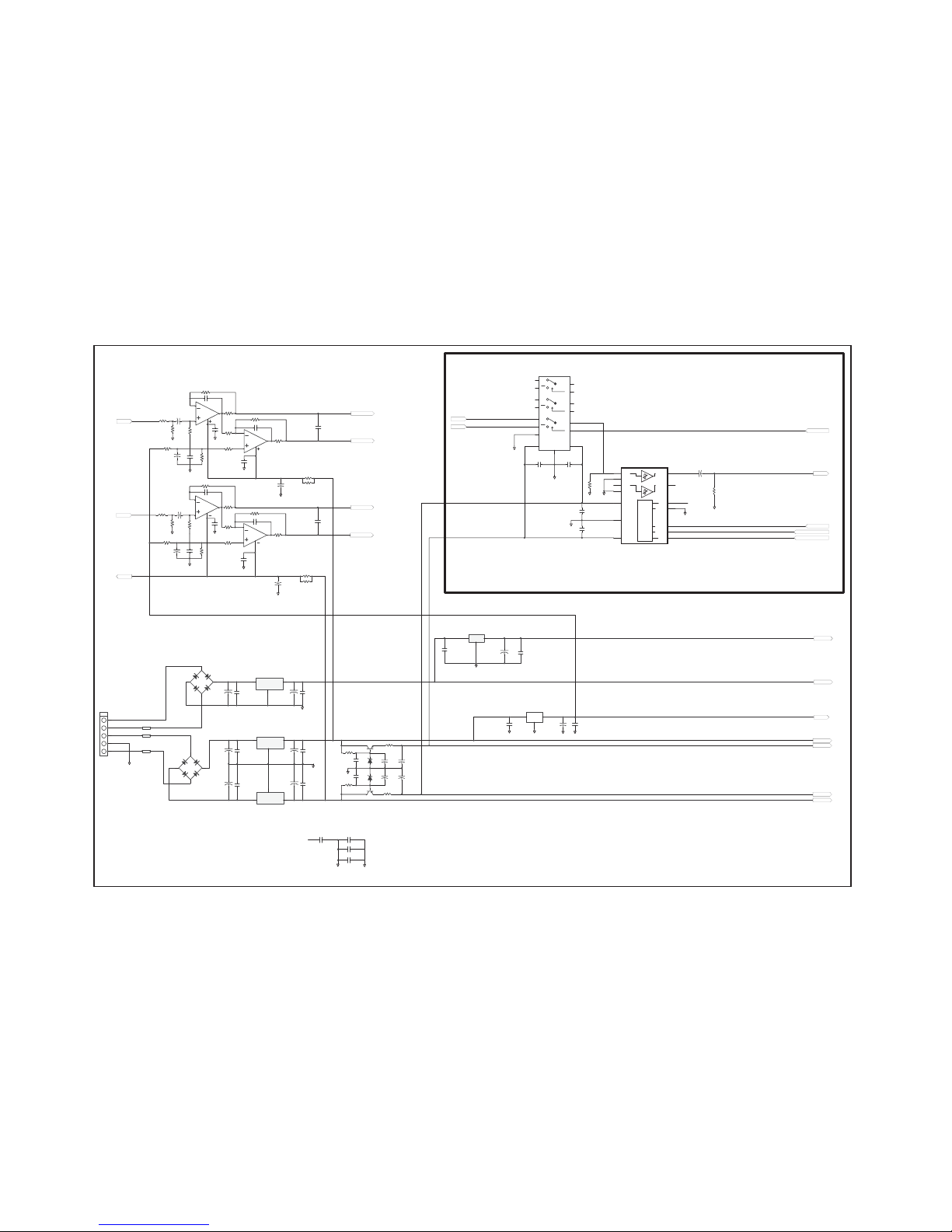
Cambridge Audio Azur 540R V2.0 AV Receiver
Decoder PCB Schematic (3 of 3)
6
5
7
8
IC20B
2068
6
5
7
8
IC21B
2068
C85
471
R121
2.8K
R133 634
R141
90.9
R134
634
R135
634
R142
90.9
R51
10K
R145
332
R139
3.32K
R123
1K
C86 471
C50
104
C51
104
C52
104
+
C99
100/10
+
C98
100/10
C108
272M
AGND
AGND
AGND
AGND
2
3
1
4
IC20A
2068
2
3
1
4
IC21A
2068
C87
471
R122
2.8K
R136 634
R143
90.9
R137
634
R138
634
R144
90.9
R52
10K
R146
332
R140
3.32K
R124
1K
C88 471
C53
104
C54
104
C55
104
+
C101
100/10
+
C100
100/10
C109
272M
AGND
AGND
AGND
AGND
AINR+
AINR-
AINL+
AINL-
R-O
L-O
R119
1.5K
R120
1.5K
AGND
AGND
AGND
AGND
C56
104
C57
104
+
C102
100/10
1 3
2
IC16
KA7805A
5VA
AC1
V+
A
C2
-V
D5
DB104G
AC1
V+
A
C
2
-V
D4
DB104G
+
C138
2200/16
C114
104
1
1
2
2
3
3
4
4
5
5
5P
J2
5P2.5
VIN
1
GN
D
2
VOUT
3
U1
KA7805
+
C141
100/10
C115
104
5VD
+
C139
3300/25
C118
104
VIN
1
GN
D
2
VOUT
3
U2
KA7812
+
C143
47/25
C120
104
+
C140
3300/25
C121
104
+
C144
47/25
C119
104
VIN
2
GN
D
1
VOUT
3
U4
KA7912A
12V
-12V
R169
1W/0.22(RF)
R170
1W/0.22(RF)
R168
1W/0.22(RF)
I
3
A
1
O
2
U3
LD1117DT25
C116
104
+
C142
47/25
C117
104
AGND
2.5VD
AGND
2.5V
5VD
DGND
DGND
IN1
1
IN2
3
AGND
2
AGND
4
VEE
5
AGND
6
VCC
7
CLK
8
DATA
9
MUTE
10
DGND
11
SEL
12
OUT2
13
OUT1
14
LOGIC
IC15
BD3812F
Y1
1
Y0
2
VEE
7
VS
S
8
YCOM
15
VDD
16
X1
13
X0
12
XCOM
14
Z1
3
Z0
5
ZCOM
4
A
11
B
10
C
9
INH
6
IC14
TC4053BF
7.1 CH USE
DVDBR
DSPBR
VOL-CLK
VOL-DATA
+
C131
10U/16
R159
68K
BR
AGND
BROUT
3816MUTE
C112
104
C113
104
AGND
AGND
R61
820K
AGND
C111
104
C110
104
AGND
DVD/DSP
AGND
AGND
Q6
C2120
Q5
A950
D6
7.5V
D7
7.5V
R173
1K
R174
1K
AGND
+
C78
47/25
+
C79
47/25
+
C80
47/25
+
C81
47/25
+7V
-7V
14.5V~
14.5V~
7.5V~
R171
6.8
R172
6.8
C145
333
C146
333
+
C132
100/16
+
C133
100/16
R148
150
R147
150
R149
150
R150
150
AGND
AGND
C58
104
C59
104
CE
C60
104
C61
104
DGND
AGND
-vv
15NC12
To enhance viewing, please print to A3 13
 Loading...