

Page 1

340C
Issue Date: 30th November 2004
________________________________________________________________________
SERVICE MANUAL
________________________________________________________________________
SPECIFICATIONS:
D/A Converter Crystal
CS4338
24-Bit/96kHz
Capable
Freq response (-0.5dB) 10Hz to 20kHz
THD 0.007%
Dynamic Range > 89dB
Digital Outputs Opt and Coax
Dimensions mm (HxWxD) 70 x 430 x 310
Weight (kg) 4.6
AP16820/1
Gallery Court Hankey Place London SE1 4BB UK
Tel: +44 (0)20 7940 2200 Fax: +44 (0)20 7940 2233
Page 2

340C SERVICE MANUAL
TABLE OF CONTENTS
Safety Precautions & Important Notes 3
Laser Safety Precautions 4
Exploded Assembly Drawing 5
Front Panel PCB Schematic 6
Front Panel PCB Layout (Top Side) 7
Front Panel PCB Layout (Bottom Side) 8
Output PCB Schematic 9
Output PCB Layout (Top Side) 10
Output PCB Layout (Bottom Side) 11
Mains PCB Schematic 12
Mains PCB Layout (Top Side) 13
Mains PCB Layout (Bottom Side) 14
Servo PCB Schematic
Servo PCB Schematic (Power Supply) 16
Servo PCB Layout (Top Side)
Servo PCB Layout (Bottom Side) 18
Front Panel PCB BOM 19
Output PCB BOM 20
Main Assembly BOM 21/22
Servo PCB BOM 23/24
IC Pin Layout Details 25-29
15
17
Page 3

SAFETY PRECAUTIONS & IMPORTANT NOTES
1.Check that the rear of the product indicates the correct supply voltage
for you area.
2. The lighting flash with the arrowhead within an equilateral
triangle is intended to alert the user or service agent to the
presence of dangerous voltages within the product enclosure
that may be of sufficient magnitude to constitute a risk of
electric shock to persons.
3. The exclamation point within an equilateral triangle is
intended to alert the user or service agent to the presence of
important operating and maintenance (Servicing) instructions
in the literature accompanying the appliance.
4. This product complies with EEC Low Voltage (73/23/EEC) and
Electromagnetic Compatibility (89/336/EEC) Directives when used and
serviced in accordance with this manual. For continued compliance all
components marked safety and EMC critical must only be replaced by
Cambridge Audio approved parts.
5. Any unauthorised design alterations or additions will void the
manufacturer’s warranty; furthermore the manufacturer cannot accept
responsibility for personal injury or property damage resulting therefrom.
6. When servicing, care should be taken to observe the original routing
and dressing of the leads and it should be confirmed that they have been
returned to normal after re-assembly.
Notes on chip component replacement
Never reuse a component that has been removed from a PCB
Notice that the minus side of a tantalum capacitor may be damaged by heat
COPYRIGHT NOTICE.
© 2005 Audio Partnership PLC. All rights reserved.
Cambridge Audio and Azur are registered trademarks of Audio Partnership PLC. This document
may not be reproduced, distributed, transmitted, displayed, published, or broadcast without the
express written prior permission of Audio Partnership PLC.
Alteration or removal of any trademark, copyright, or other notice from this content is prohibited.
Information provided in this document is provided solely for the use of official service agents in
repairing and servicing Audio Partnership PLC products.
Page 4

LASER SAFETY PRECAUTIONS
y
Caution: These labels may be attached to the unit on the rear and inside to
inform that it contains a laser component. Use of controls or adjustments, or
performance of procedures other than those specified within the service or
instruction manual may result in hazardous radiation exposure.
CLASS 1 LASER PRODUCT
WARNING!
1. Service should only be performed by qualified personnel.
2. This equipment has been designed and manufactured to meet
international safety standards; it is the legal responsibility of the repairer to
ensure that these safety standards are maintained.
3. Any repairs must be made in accordance with the relevant safety
standards.
4. It is essential that safety and EMC critical components are replaced with
Cambridge Audio approved parts only.
NOTES ON HANDLING THE OPTICAL PICK-UP BLOCK OR BASE UNIT
The laser diode in the optical pick-up block may suffer electrostatic breakdown because of the
potential difference generated by the charged electrostatic load, etc. on clothing and the human
body.
During repair, pay attention to electrostatic breakdown and also use the procedure in the printed
matter which is included in the repair parts.
The flexible board is easily damaged and should be handled with care.
NOTES ON LASER DIODE EMISSION CHECK
The laser beam on this model is concerated so as to be focused on the disc reflective surface b
the objective lens in the optical pick-up block. Therefore, when checking the laser diode
emission, observe from more than 30cm away from the objective lens.
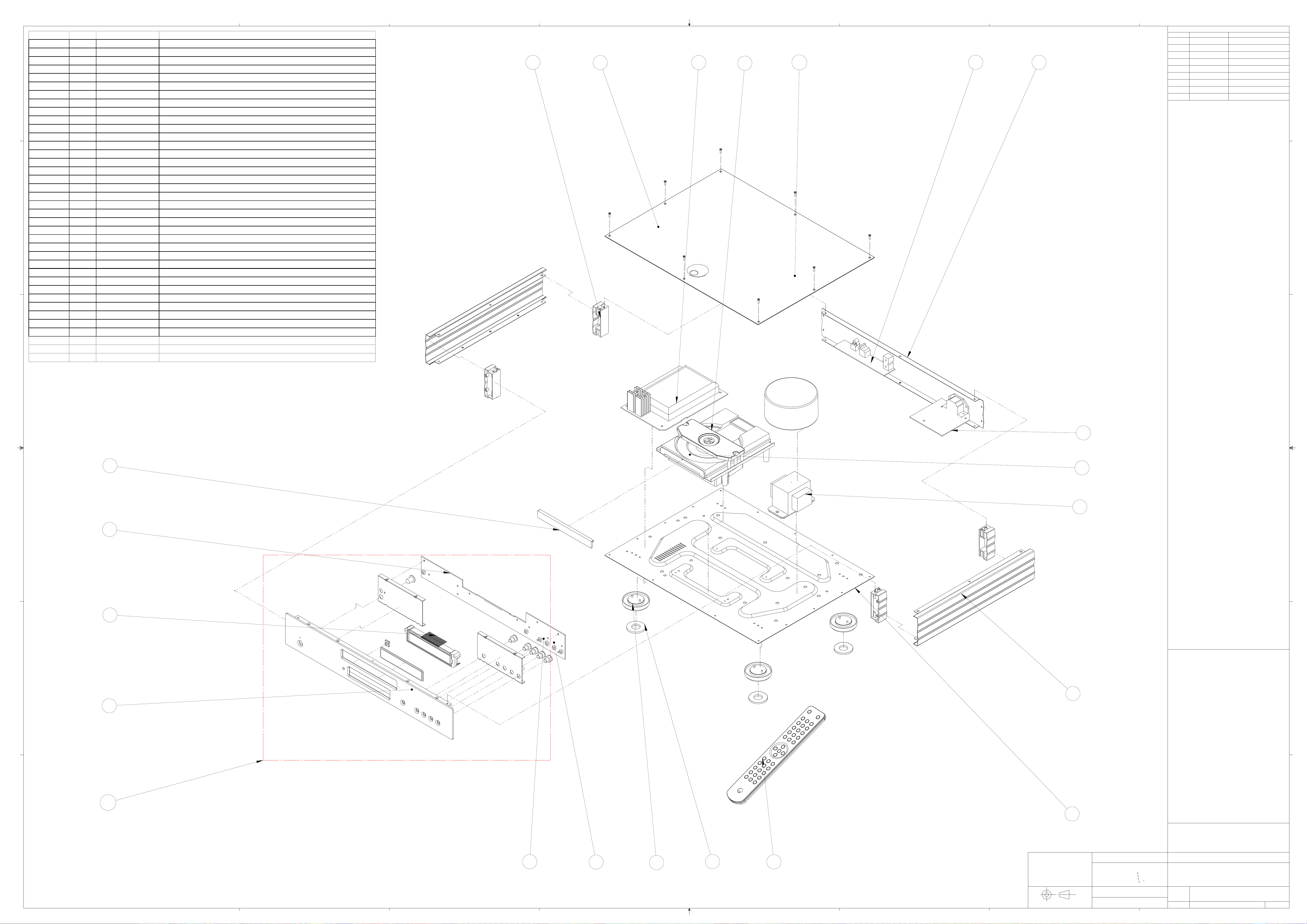
Page 5
8
Drawing ref AP part Factory ref Description
1 CA new side panel
7
6
5
4
3
2
REV
1
EDITOR
GTL
1
REVISIONS & DATE
DATE
26/11/04
2 CA new plastic insert rear
2
6
15
11
5
16
4
3 CA new plastic insert front
4 CA new back panel
5 PY507 6550-010204-000-01 Azur 640C Top Panel Black
F
5 PY508 6550-010204-000-02 Azur 640C Top Panel Silver
6 PY515 7002-608010-001 Screw M2.6 x 8 M/C Torx Recessed 1/K Head Black
REVISIONS NOTES:-
F
6 PY516 7002-608010-006 Screw M2.6 x 8 M/C Torx Recessed 1/K Head En-Plated (silver)
1: ORIGINAL DRAWING 26/11/04.
7 PY792 6564-010001-000A04 Azur-340C FRONT PANEL Silver (Aluminium panel)
7 PY786 6564-010001-000-04 Azur-340C aluminium FRONT PANEL-Black W/S Cool grey 7C
8 PY791 8534-001010-301 Azur-340C Complete FRONT PANEL ASSY (Silver) REV A
8 PY785 8534-001020-301 Azur-340C Complete FRONT PANEL ASSY (BLACK) REV A
9 PY563 3200-576690-100 TRANSFORMER 115V/230V AC10V/2A 16*2/0.5A ES-57-669
10 PY541 6050-150010-000A01 PLASTIC FOOT GREY PAINT SILVER
10 PY531 6050-150010-000 PLASTIC FOOT BLACK (AP126522)
11 PY340 9692-006002-101 Mechan Assy (PU92TL-210) W/Sony KSM213CCM ReV A
12 PY790 3009-213000-000 Sony laser assy KS213CCM
13 PY719 6050-150012-000-01 7MM TAC SWITCH BUTTON (BLACK)
13 PY720 6050-150012-000A01 7MM TAC SWITCH BUTTON (SILVER)
E
14 PY704 6600-170104-000 CA NEW RANGE AMP 7MM TAC SWITCH CUSHION
E
15 PY787 9434-001000-011 Azur-340C MAIN BOARD ASSY (AP146471) REV A
16 PY789 9434-001000-531 Azur-340C OUTPUT BOARD ASSY AP14647/4 REV A
17 PY788 9434-001000-071 Azur-340C 230V POWER PCB ASSY REV A
18 PY573 9805-064001-000 Azur-340/540/640AC REMOTE CONTROL ASSY
19 PY544 6600-170100-000 FOOT PAD FOR Azur-640A
20 PY568 6564-010006-000A01 Azur-640C.Silver CD DOOR W/SILKSCREEN PMS COOL GREY 7C
20 PY554 6564-010006-000-01 Azur-640C.Black CD DOOR W/SILKSCREEN PMS COOL GREY 7C
21 PY552 3110-064580-100 LCD DISPLAY ISO6458P01V0 113*25.7MM NEGATIVE (BLACK UNIT)
21 PY562 3110-064580-000 LCD DISPLAY ISO6458P00V0 113*25.7MM POSITIVE (SILVER UNIT)
22 PY556 9464-001000-041 Azur-540C & 640C CONTROL BOARD ASSY REV A
Note:user manual is downloadable from our www.cambridge-audio.co.uk
D
D
17
20
12
9
C
C
22
21
DRAWING NOTES:-
B
B
1
7
8
3
A
COPYRIGHT
AUDIO PARTNERSHIP PLC
14
8
7
6
13
19
5
10
18
4
3
3 GALLERY COURT
HANKEY PLACE
LONDON SE1 4BB
TEL: 0207 940 2200
FAX: 0207 940 2233
E-MAIL grahame@audiopartnership
E-MAIL nick@audiopartnership
E-MAIL simon.freeth@audiopartnership
PROJECTION
THIRD ANGLE
2
UNLESS OTHERWISE SPECIFIED:
DIMENSIONS ARE IN MM's
TOLERANCES:
WHOLE NO.s IE 75 0.5mm
1 DECIMAL IE 75.5 0.2mm
ANGULAR
MATERIAL:
FINISH:
0.1mm2 DECIMAL IE 75.75
0.5
--
--
PROPRIETARY AND CONFIDENTIAL
THE INFORMATION CONTAINED IN THIS DRAWING IS THE SOLE PROPERTY OF
AUDIO PARTNERSHIP PLC.
ANY REPRODUCTION IN PART OR AS A WHOLE WITHOUT THE WRITTEN PERMISSION
OF AUDIO PARTNERSHIP IS PROHIBITED.
AUDIO PARTNERSHIP PLC
TITLE:
340C EXPLODED ASSEMBLY
DRAWING.
SIZE
A0
1:5SCALE:
DWG. NO.
AP16809/1
DO NOT SCALE FROM DRAWING
1
OF 1SHEET
A
1
Page 6

Cambridge Audio Azur 340C CD Player
CN2
CONN-H8
CN3
CONN-H8
CN4
CONN-H7
CN7
CONN-H7
1
2
3
4
5
6
7
8
1
2
3
4
5
6
7
8
1
2
3
4
5
6
7
+5V
1
RESET
2
PWR DET
3
4
5
6
7
LCD1
COM0
1
COM1
2
COM2
3
COM3
4
SEG0
5
SEG1
6
SEG2
7
SEG3
8
SEG4
9
SEG5
10
SEG6
11
SEG7
12
SEG8
13
SEG9
14
SEG10
15
SEG11
16
SEG12
17
SEG13
18
SEG14
19
SEG15
20
SEG16
21
SEG17
22
SEG18
23
LCD
PACKAGE=LCD D600
+5V
R15
330R
C4
100n
R6
K1
10K
C2
1000p
R11
K2
3K3
C3
1000p
SW1
PLAY/PAUSE
SW3
OPEN/CLOSE
U2
+5V
3
GND
2
OPT
1
TSOP18 IR RECEI
R5
2K7
R10
68K
SW2
STOP
R3
27KR433K
+5V
FORWARD SKIP FORWARD SEARCH
R8
1K5
BACKWARD SKIP BACKWARD SEARCH
U3
1
2
3
4
5
6
7
16C505
C1
100n
VDD
RB5/OSC1/CLKIN
RB4/OSC2/CLKOUT
RB3/MCLR/VPP
RC5/TOCKI
RC4
RC3
R9
82K
R7
82K
C6
10uF 10V
14
VSS
13
RB0
12
RB1
11
RB2
10
RC0
9
RC1
8
RC2
SW6
SW-TACT
CN1
CONN-H2
SW4
SW-TACT
1
2
R12
4K7
Q2
BC327
SW5
SW-TACT
+5V
R13
10K
CN5
CONN-H3
CN6
CONN-H3
1
2
3
R14
820R
D2
LED
Standby
1
2
3
R1
820R
P2
PAD
P1
PAD
R16
33R
Q1
BC337
R2
1K8
D1
1N4148
D3
1N4148
AP12992/3 Front Panel PCB Schematic
PGND
Page 7

Cambridge Audio Azur 340C CD Player
AP12992/3 Front Panel PCB Layout (Top Side)
Page 8

Cambridge Audio Azur 340C CD Player
AP12992/3 Front Panel PCB Layout (Bottom Side)
Page 9

Cambridge Audio Azur 340C CD Player
CN2
Analogue O/P
U2:B
3 4
74HC14
U2:C
5 6
DGND
DOUT
R1
VCC
1
2
3
3
R3
47R
3
2
1
C6
4.7n cer
EMC
CN1:B
ZUANBAOAV2-8,4-13EL
C1
RIGHT CHANNEL
4.7n cer
EMC
C2
4.7n cer
EMC
4
1
2
CN1:A
ZUANBAOAV2-8,4-13EL
LEFT CHANNEL
AGND
Data In
+5V
CN3
74HC14
U2:D
13 12
74HC14
100R
R2
10R
C9
C4
100nF
100nF
GND
U2:F
9 8
74HC14
U2:A
1 2
74HC14
U2:E
11 10
74HC14
C5
10u 16V
DGND
R32
430R
2
3
1
C3
100nF
U1
VCC
INPUT
GND
APTX179AT
R31
FB1
FERRITE BEAD 5uH
C7
91R
330pFC8330pF
FB2
FERRITE BEAD 5uH
C25
100nF
DGND
CN4
ZUANBAO AV-8,4-8ES
3
1 2
C26
100nF
AP14644/4 Output PCB Schematic
Page 10

Cambridge Audio Azur 340C CD Player
AP14644/4 Output PCB Layout (Top Side)
Page 11

Cambridge Audio Azur 340C CD Player
AP14644/4 Output PCB Layout (Bottom Side)
Page 12

Cambridge Audio Azur 340C CD Player
CN3
IEC-SOC
FU3
L
earth
E
N
C2
X1 10n
C1
X1 10n
C3
X2 680N SUPPRESSION
20MM T1AL
J3
BROWN
J2
BLACK
CN1
CONN-H3
FU1
20MM F1AL
1
2
3
FU2
20MM F1AL
1
2
3
CN2
CONN-H3
J1
BLUE
AP13637/4 Mains PCB Schematic
Page 13

Cambridge Audio Azur 340C CD Player
AP13637/4 Mains PCB Layout (Top Side)
Page 14

Cambridge Audio Azur 340C CD Player
AP13637/4 Mains PCB Layout (Bottom Side)
Page 15

SEG18
SEG17
SEG16
SEG15
SEG14
SEG13
SEG12
SEG11
SEG10
SEG9
SEG8
SEG7
SEG6
SEG5
SEG4
SEG3
SEG2
SEG1
SEG0
COM3
COM2
COM1
COM0
RESET
BOOT
GND
WAIT
SCK2
SO2
SET LCD CONTRAST
+5V
SI2
PROGRAMMING
Cambridge Audio Azur 340C CD Player
CN7
R36
100K no stuff
C14 22uF 16V
D8
1N4148 no stuff
7
REMOTE
6
+5V
5
GND
4
K1
3
K2
2
PWR DET
1
RESET
CONTROL KEYS
+8V
R67
27R 1W
R33
Q9
Q10
8550
8550
470R
R28
10K
Q8
8050
D10
Q7
1N4148
D11
1N4148
+5V
R64
10K
C28 47uF 16V
C31 2200pF no stuff
C30 2200pF no stuff
C12
1uF 16V
C13
0.047uF
C29
47uF 16V
Q12
8050
8050
CN20
1
2
MUTE
CN12
5
4
3
2
1
AUDIO OUT no stuff
CN18
1
2
XTALO no stuff
CN17
1
2
XTALI
C87
1nF
C17
15pF
X1
C15
CRYSTAL
0.047uF
16.9344MHz
C16
15pF
10R 1/4W
R40
XVDD
81
10K no stuff
DVSR
R38
82
RO
83
DVDD
84
DVR
85
LO
86
10K no stuff
DVSL
R37
87
TEST1
NC
88
TEST2
NC
89
TEST3
NC
90
BUS0
91
BUS1
92
BUS2
93
BUS3
94
VDD
95
VSS
96
BUCK
97
CCE
98
TEST4
NC
99
TSMOD
NC
100
RST
TEST01HSO2UHSO3EMPH4LRCK5VSS16BCK7AOUT8DOUT9MBOV10IPF11SBOK12CLCK13VDD114VSS215DATA16SFSY17SBSY18SPCK18SPDA20COFS21MONIT22VDD223TESIO024P2VREF25HSSW26ZDET27PDO28TMAXS29TMAX
NCNCNC
CN2
5
GND
4
LRCK
3
PCMD
2
BCK
1
EMPH
DATA OUT
+5V
CN1
1
D-OUT
2
+5V
3
GND
DIGITAL OUT
REMOTE
CN6
1
2
3
4
5
6
7
LCD
CN5
1
2
3
4
5
6
7
8
LCD
CN4
1
2
3
4
5
6
7
8
LCD
+5V
R22
no stuff
R21
1K
L5
100uH
L4
C83
470uF 16V
C84
220uF 16V
C82
10uF 16V
R20
1K
NC
NC
NC
100
100uH
C85
100uF 16V
X2
CRYSTAL
7.3728MHz
+5V
C81
25pF
R19
3K3
D9
1N4148
SANYO MECH SONY MECH
R30 10K
R54
33K
R38
56K
R43
56K
R36
10K
R37 10K
R38
10K
R39 10K
R3K3
R52
12K
C47 1pF
+5VCC
+5VDD
CN3
1
2
3
4
5
6
7
8
NCNCNCNCNCNCNCNCNCNCNCNCNCNCNCNCNCNCNC
73NC72NC71NC70NC69NC68NC67NC66NC65NC64NC63NC62NC61NC60NC59NC58NC57NC56NC55NC54NC53
80
SEG1477SEG1576SEG1675SEG1774SEG18
SEG1378SEG1279SEG11
81
SEG10
82
SEG9
83
SEG8
84
SEG7
85
SEG6
86
SEG5
87
SEG4
88
89
90
91
92
93
94
95
96
97
98
99
U3
SEG3
TOSHCDMCU
SEG2
SEG1
SEG0
COM3
COM2
COM1
COM0
VLC
NC
NC
NC
VDD
VSSS1XOUT2XIN3RESET4NC5NC6TEST7NC8REMOTE9MUTE10NC11NC12NC13SCK214(SI2)15(SO2)16(WAIT)17NC18NC19NC20NC21NC22NC23NC24NC25NC26NC27NC28CORW29RES
NCNCNC
NCNCNCNCNCNCNCNCNCNCNCNCNC
REMOTE
C80
25pF
R76
4K7
C79
Q13
100nF
9014C
R18
10K
R30 *
3K3
R54 *
47K
R38 *
33K
R43 *
33K
R36 *
5K1
5K1
R37 *
5K1
R38 *
5K1
R39 *
NC
R *
15K
R52 *
5pF
C47 *
+5V
R27
10K
LK1
+5VDD
LINK
OPEN = F/L
C86
SHORT = T/L
NC
NC
+5V
2K2
R66
10K
R17
R65
10K
L3
100uH
100nF
52
51
VDD
FL/TL
VSS
(BOOT)
VAREF
AD K1
AD K2
AD K3
PWR DET
NC
NC
OLT
CLT
SLT
D-OPEN
D-CLOSE
BUS3
BUS2
BUS1
BUS0
BUCK
CEE
30
R26 10K
R25 1K
R23 10K
50
49
48
47
46
45
44
43
NC
42
NC
41
40
39
38
37
36
35
34
33
32
31
R24 10K
R32
4K7
R35
100K no stuff
+5V
R39
10K
R15 10K
R14 10K
R13 10K
R12 10K
R11 10K
R16
10K
+5V
R31
R30
10K
10K
R34
470R
Q11
8050
CN8
5
CLT
4
GND
3
OLT
2
CLOSE
1
DRAW DRIVE
OPEN
+5V+5V
R29
10K
+8V
C24
470pF
C25
470pF
10K
R44
MUTE
MUTE1
ROUT
GND
LOUT
GND
GND
OSC
80
XI
R10
C26
0.047uF
C27
0.047uF
R42
R41
3K3
C19
0.047uF
74
73
72
PXI
VSS4
TESIO1
NCNCNCNCNCNCNCNCNCNCNC
71
70
69
68
IO367IO266IO165IO0
CKSE
TESIN
DACT
DMOUT
C18 47uF 16V
64
63
62
61
60
59
VSS3
FLGB
FLGA
FLGC
FLGD
VDD3
NC
77
76
75
78XO79
PXO
XVSS
VDD4
TC9462F
NCNCNCNCNCNCNCNCNCNCNC
47R
R43
3K3
NC
58
57
56
55
SEL
DMO
2VREF
TEBC254TEBC153TEBC0
NC
C11
0.047uF
R45
3K3
3K3
3K3
R46
3K3
R47
C23
0.047uF
C70
47uF 16V
U2
52
51
RFGC
50
VREF
49
TRO
48
FOO
47
TEZI
46
TEI
45
TSIN
44
SBAD
43
FEI
42
RFRP
41
RFZI
40
RFCT
39
AVDD1
38
RFI
37
SLCO
36
AVSS1
35
VCOF
34
VCOREF
33
PVREF
32
LPFO
31
LPFN
C8
C76
0.015uF
47pF
30
R6
220K
C10
47uF 16VC947uF 16V
C74 47uF 16V
R5 15K
R9 47K
R7 68K
R8 10K
C22 0.047uF
C21
4.7n Mylar
R60
1K
47K
R61
C4
C3
C72
C71
C73
56pFR215K
R3
1K
100nF
220R
R4
C1
5pF
R63
R1
100K
2K2
C78
47uF 16V
C7
C5
C77
0.0047uF
0.047uF
47uF 16V
C75 0.01uF
C6 0.0027uF
U1
100nF
16
SBAD15FEO
17
TEO
FEN
18
TEN
SEB
19
2VRO
0.22uF
0.22uF
VRO
20
TEB
RFRP
21
SEL
BTC
22
LDO
RFCT
23
MDI
PKC
24
TNI
RFRPIN
25
RFGO
TPI
26
FPI
GVSW
27
FNI
AGCIN
28
GMAD
RFO
29
RFGC
GND
30
VCC
RFN2
TA2153FN
C2
100nF
L1
47uH
C59
C60
0.047uF
R59
82K
14
13
12
11
10
9
8
7
6
5
4
3
2
1
C65
C66
0.047uF
47uF 16V
U6
100nF
1
24
PW GND
PW GND
2
23
OUT(-)1
OUT(-)4
3
22
PVCC1
PVCC4
4
21
OUT(+)1
OUT(+)4
5
20
VIN1
VIN4
6
19
VRI
S VCC
7
18
VCI
S GND
8
17
VIN2
VIN3
9
C61
100nF
C20
47uF 16V
16
OUT(+)2
OUT(+)3
10
15
PVCC2
PVCC3
11
14
OUT(-)2
OUT(-)3
13
PW GND12PW GND
TA2092N
C56
220uF 16V
C62
100nF
Q1
L2
R62
9015
100uH
10R
C69
10uF 16V
33K
R52
47K
R51
47K
R50
47K
R49
47K
R48
33K
R57
C64
100nF
C67
100nF
5K1
R56
5K1
R55
5K1
R54
5K1
R53
CN15
6
SLT-
5
SLT+
4
C57
100nF
C58
100nF
FM+
3
FM-
2
DM-
1
DM+
MOTOR DRIVE
CN16
16
FC-
15
TR-
14
TR+
13
FC+
12
PD
100R
11
R58
VR
10
LD
9
GND
8
F
7
C
6
B
5
A
4
D
3
E
2
VCC
1
VC
MECH
C68
100nF
AP14792/2 Servo PCB Schematic
Page 16

Cambridge Audio Azur 340C CD Player
CN21
1
2
C54
CN19
AC IN
AC
100nF
1
2
IN4004
D5
D2
D4
D3
IN4004
C53
100nF
C51
100nF
14.5V
IN4004
FU1
T2AL
IN4004
C52
100nF
FP DIS
U7
7808
3
VI1VO
GND
2
C50
C49
3300uF 25V
100nF
+8V
C47
C48
470uF 16V
100nF
C44
100nF
U8
7805
VI1VO
2
GND
+5V
3
C45
100nF
C46
470uF 16V
14.5V
R83
120R 0.5W
R88
1K
R89
330k
D1
IN4148
R90
390R
47uF 16V
R87
100R
Q6
C55
9012
D6
IN4004
R86
3K9
R85
C63
560R
4.7uF 16V
D7
IN4004
R84
AC
4K7
RL1:A
1
2
Q4
8050
Q5
9012
Q3
8050
CN13
DIG DATA
+5V
15K
C39
10uF 25V
1
2
3
4
5
CN14
2
1
MCLK
U5
1
2
3
4
C88
1nF
8
SDATA
AOUTL
7
DEM/SCL
VA+
6
LRCK
AGND
5
MCLK
AOUTR
CS4338
C32
10uF 25V
R82
C40
C41
10uF 25V
0.1uF
C42
390pF
15K
R75
+8V
12K
R80
C38
390pF
12K
R74
GND
C36
10pF
47K
R81
84
U4:A
3
1
2
TS922IN
15K
R72
15K
R79
C37
220uF 16V
U4:B
5
7
6
TS922IN
47K
R73
C33
10pF
C43
100uF 16V
C34
100uF 16V
R70
47K
R71
47K
C35
0.1uF
R68
47R
RL1:B
4
3
5
CN9
1
L.CH
2
GND
3
R.CH
RL1:C
8
6
7
R69
47R
CN11
5
MUTE
4
MUTE1
3
ROUT
2
GND
1
LOUT
AUDIO OUT no stuff
CN10
1
L.CH
2
GND no stuff
3
R.CH
AP14792/2 Servo PCB Schematic (Power Supply)
Page 17

Cambridge Audio Azur 340C CD Player
AP12927/7 Servo PCB Layout (Top Side)
Page 18

Cambridge Audio Azur 340C CD Player
AP12927/7 Servo PCB Layout (Bottom Side)
Page 19

T
Cambridge Audio Azur 340C Front Panel PCB
AP13578/3
AP PART NO. VALUE DESCRIPTION QTY COMPONENT IDEN
RESISTORS
33R Resistor 0.25W 1% metal film 1 R16
330R Resistor 0.25W 1% metal film 1 R15
820R Resistor 0.25W 1% metal film 2 R1, R14
1K5 Resistor 0.25W 1% metal film 1 R8
1K8 Resistor 0.25W 1% metal film 1 R2
2K7 Resistor 0.25W 1% metal film 1 R5
3K3 Resistor 0.25W 1% metal film 1 R11
4K7 Resistor 0.25W 1% metal film 1 R12
10K Resistor 0.25W 1% metal film 2 R6, R13
27K Resistor 0.25W 1% metal film 1 R3
33K Resistor 0.25W 1% metal film 1 R4
68K Resistor 0.25W 1% metal film 1 R10
82K Resistor 0.25W 1% metal film 2 R7, R9
CAPACITORS
1000pF 5mm Pitch 2 C2, C3
100nF 5mm Pitch 2 C1, C4
10uF 10V 2.5mm Pitch Electolytic 1 C6
INTERGRATED CIRCUITS
PY054 TSOP18 IR Receiver 1 U2
PY605 16C505 PIC 1 U3
TRANSISTORS
PY214 BC337 NPN small signal transistor 1 Q1
PY219 BC327 PNP small signal transistor 1 Q2
DIODES
1N4148 Small signal diode 2 D1, D3
PY064 Blue LED 3mm Blue flat top LED 1 D2
MISC.
2way JST 90deg 2mm pitch 1 CN1
3way JST 90deg 2mm pitch 2 CN5, CN6
7way JST 90deg 2mm pitch 2 CN4, CN7
8way JST 90deg 2mm pitch 2 CN2, CN3
PY562 for Silver
PY552 for Black
PY556 AP12993/3
AP13337/*
AP13333/*
AP13344/* LCD holder 1
AP13438/* LCD backlight foam spacer 1
2400-020200-000 TACT SW 2P2T KPT-1105A (5MM) 6 SW1, 2, 3, 4, 5, 6
Azur range CD LCD 1 LCD1
LCD back light assembly 1
M3 x 8 Pozi Pan Plastite Screws 2 to hold LCD holder to PCB
Schematic AP12992/3
Azur CD Front Panel PCB, single sided,
blue
Gerber file is
1
AP12993/3
PCB Construction
details AP12994/3
NOTES
Programmed with AP13762/*
software
YN:3110-064580-000 LCD
Display ISO6458P00V0
113*25.7MM positive
YN:3110-064580-100 LCD
Display ISO6458P01V0
113x25.7mm negative
Complete front panel PCB
Note: resistors, capacitors and other 'generic' electronic components are not usually
stocked by the manufacturer. Please obtain these locally.
Page 20

Cambridge Azur 340C Output PCB Assembly BOM
AP PART NO. VALUE DESCRIPTION QTY COMPONENT IDENT
RESISTORS
10R 0.25 W Metal Film Resistor 1 R2
47R 0.25 W Metal Film Resistor 1 R3
91R 0.25 W Metal Film Resistor 1 R31
100R 0.25 W Metal Film Resistor 1 R1
430R 0.25 W Metal Film Resistor 1 R32
CAPACITORS
330p Ceramic 50V 5mm Pitch 2 C7, C8
4n7 Ceramic 50V 5mm Pitch 3 C1, C2, C6
100n Ceramic 50V 5mm Pitch 5 C3, C4, C9, C25, C26
10u 16V Electrolytic 1 C5
SEMICONDUCTORS
PY363 APTX179AT Opto TX 1 U1
PY343 74HC14 HCMOS DIL 1 U2
CONNECTORS
Zuznbao AV2-8,4-13EL Dual RCA connector, gold plated 1 CN1
Analogue O/P 3 way 2.0mm pitch JST type connector 1 CN2
DOUT 3 way 2.0mm pitch JST type connector 1 CN3
Single RCA connector, gold plated 1 CN4
MISCELLANEOUS
5uH Inductor NKW8W 2 FB1, FB2
PCB
Schematic AP14644/3
AP14645/3 Blank PCB 1
Gerber file is AP14645/3
PCB Construction details AP14646/3
AP14647/4
Note: resistors, capacitors and other 'generic' electronic components are not usually
stocked by the manufacturer. Please obtain these locally.
Page 21

A
Cambridge Azur 340C CD Player Main Assembly BOM (Silver UK)
P DRAWING
NO
AP12735/5 Bottom Panel 1
AP12652/2
AP12883/3 PY544 Azur Foot Pad 4 Affix on Foot Using Adhesive Surface
AP13571/1 Cambridge Audio New Range CD Transformer Pad 1
AP13157/3 PY563 Cambridge Audio EI 115/230v 540c/640c Transformer 1 Position On Transformer Pad With Fixing Bolts Through Supplied Holes
AP13545/1
AP13544/3 Cambridge Audio New Range CD Mech Top Sticker 1
AP13495/1
AP13617/1 16 Way Laser Cable, Flexible Flat Cable 250mm 1 Connects Servo PCB To Laser Block On The CD Mech
AP13618/1 5 Way Tray Motor Cable Flat Wire Style 350mm 1
AP13619/1 6 Way Spindle Motor Cable 200mm 1 Connects The Servo PCB To The CD Mech, Runs Under The CD Mech
AP13895/1 Mains PCB Insulating Sheet 1
AP12935/1 IR Lens 1 Glued In Place On The Front Panel
AP13322/2 105mm Display Window (Mirrored) 1 Glued In Place On The Front Panel
AP13436/2 Sub Panel Left 1
AP12931/1 Lightguide, Cut To Single Pipe 1 Fasten To Subplate Left
AP13585/1 9mm TAC Switch Cushion 1
AP11782/1 Opus Control Box Button (9mm) 1 Position in Place on the Front Panel
AP13437/2 Sub Panel Right 1
AP12934/1 PY704 7mm TAC Switch Cushion 5
AP12925/1
AP13578/3 Front Panel PCB Assembly BOM 1 Fixes onto the Sub Panels With M3 M/C Screws
AP12725/2 Pressed Side Panel (2 Ridge) 2
AP12727/1
AP12728/1 Rear Plastic Support (2 Ridge With Captive M2.6 Nuts) 2 Position at Rear within Side Panels
AP13435/2 Rear Panel Printed 1 Screened With Artwork AP14835/1
AP14647/2 PY789 Output PCB Assembly BOM 1 Mounted directly on the rear panel
AP13620/1 8 Way LCD Cable, Flat Wire Style 280mm 2
AP13621/1 7 Way LCD Cable, Flat Wire Style 500mm 1
AP13622/1 7 Way Control Cable 520mm 1
AP13623/1 3 Way Standby Cable 380mm 1
AP13624/1 2 Way Backlight Power Cable 440mm 1
AP13626/1 3 Way Shielded Digital Out Cable 2 From DAC PCB to rear panel PCB assembly
AP13340/1 Lidding Tape For Front And Rear Panels 2 Fix To The Correct Surfaces For Lid
AP13342/1 Lidding Tape For Side Panels 2 Fix To The Correct Surfaces For Lid
AP12733/2
AP PART NO DESCRIPTION QTY NOTES
PY531 - Black
PY541 Silver
PY340
PY568 Silver
PY554 Black
PY719 Black
PY720 Silver
PY507 Black
PY508 Silver
Azur Foot Moulding 4 Position In Place on Bottom Panel
Position In Place On Bottom Panel With The Fixing Bolts Through
Supplied Holes
Heatshrink sleeve 70mm For transformer wires
Ferrite Ring 1 Added to secondary wires of transformer (3 turns x 3 wires)
Cambridge Audio New Range CD Transformer Can
With Adhesive Pad Added
Yanion Version Of Sony CD Mech With Sony Laser
Block (PY790)
Cambridge Audio New Range CD Draw Front 1
Front Panel Assembly
M3 X 6 Pozi Pan Stp Screw 1 Affixes Single Lightguide To Subplate
7mm TAC Switch Button 5 Position In Place On The Front Panel
Side Panel Assembly
Front Plastic Support (2 Ridge With Captive M2.6
Nuts)
M2.6 X 8 C/S Pozi Plastite 8 To Affix Side Panels To Plastic Inserts
Rear Panel Assembly
Final Assembly
Ferrite Tube 1 Fit ferrite over screened cables, CN2 & CN3 on output PCB
M2.6 X 6 Pozi Pan Machine Screw 15 To fix Bottom Panel To Side, Front And Rear Panels
Lidding
Top Panel Without Vents 1 Position on Top Of The Product
Screened With Artwork AP13721/1 Position On Top Of Transformer
1
And Press To Stick In Place
1 Position In The Correct Position On The Bottom Panel
Screened With Artwork AP13763/1. Then Position Over Locating Pips
On CD Mech Top Surface And Press To Stick
Screened With Artwork AP13601/1 Position On Draw Front And Glue In
Place
Connects The Servo PCB To The CD Mech, Runs Under The Front Of
The Mech And Under The Servo PCB
Cut to fit 2 standoffs. To Be Positioned Over Standoffs Under Power
PCB
Fasten in place between the Ledges of the Front Panel, Align Up The
Power Button Holes
Position on the 9mm tact switch button, down the main shaft affix using
adhesive provided on the cushion.
Fasten in place between the Ledges of the Front Panel, Align Up The
Function Button Holes
Position on the 7mm tact switch Buttons, down the main shaft affix using
adhesive provided on the cushion.
2 Position at Front within Side Panels
Connects The Front Panel PCB To The Servo PCB, Runs Around The
Side Of The Casework
Connects The Front Panel PCB To The Servo PCB, Runs Around The
Side Of The Casework
Connects The Front Panel PCB To The Servo PCB, Runs Under The CD
Mech Then Around The Outside Of The Casework
Connects The Front Panel PCB To The Stand By PCB, Runs Underneath
The CD Mech
Connects The Front Panel PCB To The Servo PCB, Runs Under The CD
Mech Then Around The Outside Of The Casework
AP15162/2
Note: resistors, capacitors and other 'generic' electronic components are not usually stocked by the
manufacturer. Please obtain these locally.
Page 22

A
Cambridge Azur 340C CD Player Main Assembly BOM (Silver UK)
P DRAWING
NO
AP13612/1 Azur 2 Ridge Woven Bag 1 Pack CD Player Unit Inside
AP13504/2 Poly Endcap Packaging 2
AP13613/1 Azur Woven Bag For Remote Control 1 Pack Remote Control Inside,
AP15161/1 340C CD Player Instruction Manual 1
AP13505/1 Carton Packaging With Handle 1 Printed To Artwork AP13716/1
AP14702/1 Carton Label (Model No.) 1 For Box
AP PART NO DESCRIPTION QTY NOTES
PY515 Black
PY516 Silver
PY573
M2.6 X 6 C/S Torx Machine Screw 8 To Affix Top Panel to plastic Inserts, Side, Rear and Front Panel
Packaging
Azur Remote Control Complete. Model No RC540AC/640AC
AAA Alkaline Batteries 3 For Remote. Place In Instruction Manual Polybag
Polybag 173X260X4C mm 1 For Instruction Manual and Remote Batteries
1830mm AC IEC Power Cord Set BS Standard Fused 3
AMP
Blue Tape Seal For Cambridge Carton 1
1 Mounted into Poly Endcap, Packing in Rebate Provided
1 Must Be Bs Approved
AP15162/2
Note: resistors, capacitors and other 'generic' electronic components are not usually stocked by the
manufacturer. Please obtain these locally.
Page 23

Cambridge Azur 340C CD Servo PCB Assembly BOM
AP PART NO. VALUE DESCRIPTION QTY COMPONENT IDENT
RESISTORS
10R 0.125 W Metal Film Resistor 1 R62
10R 0.25 W Metal Film Resistor 1 R40
27R 1 W Carbon Resistor 1 R67
47R 0.125 W Metal Film Resistor 3 R10, R68, R69
100R 0.125 W Metal Film Resistor 1 R58, R87
120R 0.5W Metal Film Resistor 1 R83
220R 0.125 W Metal Film Resistor 1 R4
390R 0.125W Metal Film Resistor 1 R90
470R 0.125 W Metal Film Resistor 2 R33, R34
560R 0.125W Metal Film Resistor 1 R85
1k 0.125 W Metal Film Resistor 6 R3,R20,R21,R25,R60,R88
2k2 0.125 W Metal Film Resistor 2 R1, R66
3k3 0.125 W Metal Film Resistor 7 R19, R41, R42, R43, R45, R46, R47
3k9 0.125W Metal Film Resistor 1 R86
4k7 0.125 W Metal Film Resistor 3 R32, R76,R84
5k1 0.125 W Metal Film Resistor 4 R53, R54, R55, R56
R8, R11, R12, R13, R14, R15, R16, R17, R18,
10k 0.125 W Metal Film Resistor 21
12k 0.125 W Metal Film Resistor 2 R74, R80
15k 0.125 W Metal Film Resistor 6 R2, R5, R72, R75, R79, R82
33k 0.125 W Metal Film Resistor 2 R52, R57
47k 0.125 W Metal Film Resistor 10
68k 0.125 W Metal Film Resistor 1 R7
82k 0.125 W Metal Film Resistor 1 R59
100k 0.125 W Metal Film Resistor 1 R63
220k 0.125 W Metal Film Resistor 1 R6
330k 0.125 W Metal Film Resistor 1 R89
CAPACITORS
5p Ceramic COG 50V 5mm Pitch 1 C1
10p Ceramic COG 50V 5mm Pitch 2 C33, C36
15p Ceramic COG 50V 5mm Pitch 2 C16, C17
25p Ceramic COG 50V 5mm Pitch 2 C80, C81
47p Ceramic COG 50V 5mm Pitch 1 C76
56p Ceramic COG 50V 5mm Pitch 1 C73
390p Ceramic COG 50V 5mm Pitch 2 C38, C42
470p Ceramic 50V 5mm Pitch 2 C24, C25
1n Ceramic 50V 5mm Pitch 2 C87, C88
10n Ceramic 50V 5mm Pitch 1 C75
15n Ceramic 50V 5mm Pitch 1 C8
47n Ceramic 50V 5mm Pitch 11
100n Ceramic 50V 5mm Pitch 23
220n Ceramic 50V 5mm Pitch 2 C3, C72
2n7 Mylar 5mm Pitch 1 C6
4n7 Mylar 5mm Pitch 2 C7, C21
1u 16V Electrolytic 1 C12
4.7u 16V Electrolytic 1 C63
10u 16V Electrolytic 2 C69, C82
22u 16V Electrolytic 1 C14
47u 16V Electrolytic 12
100u 16V Electrolytic 3 C34, C43, C85
220u 16V Electrolytic 3 C37, C56, C84
470u 16V Electrolytic 3 C46, C47, C83
R23, R24, R26, R27, R28, R29, R30, R31, R39,
R44, R64, R65
R9, R48, R49, R50, R51, R61, R70, R71, R73,
R81
C5, C11, C13, C15, C19, C22, C23, C26, C27,
C60, C66
C2, C4, C35, C41, C44, C45, C48, C49, C51,
C52, C53, C54, C57, C58, C59, C61, C62, C64,
C67, C68, C71, C79, C86
C9, C10, C18, C20, C28, C29, C55, C65, C70,
C74, C77, C78
AP14776/3
Note: resistors, capacitors and other 'generic' electronic components are not usually
stocked by the manufacturer. Please obtain these locally.
Page 24

Cambridge Azur 340C CD Servo PCB Assembly BOM
AP PART NO. VALUE DESCRIPTION QTY COMPONENT IDENT
10u 25V Electrolytic 3 C32, C39, C40
3300u 25V Electrolytic 1 C50
SEMICONDUCTORS
PY474 TA2153FN TOSHIBA RF Amplifier 1 U1
PY475 TC9462F TOSHIBA Digital Servo-chip Processor 1 U2
TOSHCDMCU YANION Supplier 1 U3
PY473 TA2092N TOSHIBA Power driver IC 1 U6
PY107 CS4338 Crystal Semicon DAC IC 1 U5
PY754 TS922IN Rail to Rail Op Amp 1 U4
PY316 7808 TO-220 +8V Regulator 1 U7
7805 TO-220 +5V Regulator 1 U8
C8050 NPN Transistor 6 Q3, Q4, Q7, Q8, Q11, Q12
PY560 9012 PNP Transistor 2 Q5, Q6
PY558 9014C NPN Transistor 1 Q13
C8550 PNP Transistor 2 Q9, Q10
PY560 9015 PNP Transistor 1 Q1
1N4148 Signal Diode 4 D1, D9, D10, D11
1N4004 Rectifier Diode 6 D2, D3, D4, D5, D6, D7
CRYSTALS
PY027 16.9344MHz 2 Pin 5mm Pitch 1 X1
PY561 7.3728MHz 2 Pin 5mm Pitch 1 X2
CONNECTORS
2 Way 2mm Pitch JST 5 CN17, CN18, CN20, CN21, CN14
3 Way 2mm Pitch JST 3 CN1, CN9, CN10
5 Way 2mm Pitch JST 3 CN2, CN8, CN13
6 Way 2mm Pitch JST 1 CN15
7 Way 2mm Pitch JST 2 CN6, CN7
8 Way 2mm Pitch JST 3 CN3, CN4, CN5
2 Way 2.5mm Pitch JST 1 CN19
16 Way FFC 1.0mm Pitch 1 CN16
MISCELLANEOUS
Relay 9V SS-DPDT 1 RL1
20mm PCB Mount Fuse Holder 1 FU1
2A 20mm Fuse for above 1 FU1
47u Inductor 8mm Pitch 1 L1
100u Inductor 8mm Pitch 4 L2, L3, L4, L5
HEATSINK FOR U7 & U8 2 (U7, U8)
AP14776/3
Note: resistors, capacitors and other 'generic' electronic components are not usually
stocked by the manufacturer. Please obtain these locally.
Page 25

Cambridge Audio Azur 340C CD Player IC Pin
Layout Details
Control PCB
PIC16C505 (U3)
TSOP18 (U2)
Page 26

Output PCB
APTX179AT (U1)
74HC14 (U2)
Page 27

SERVO PCB
TA2153FN (U1)
TC9462F (U2)
Page 28

TLCS-870 MCU (U3)
TA2092 (U6)
Page 29

7808 (U7)
7805 (U8)
TS922IN (U4)
CS4338 (U5)
 Loading...