

Cambium Networks 89FT0004, 89FT0003 Users manual

Cambium
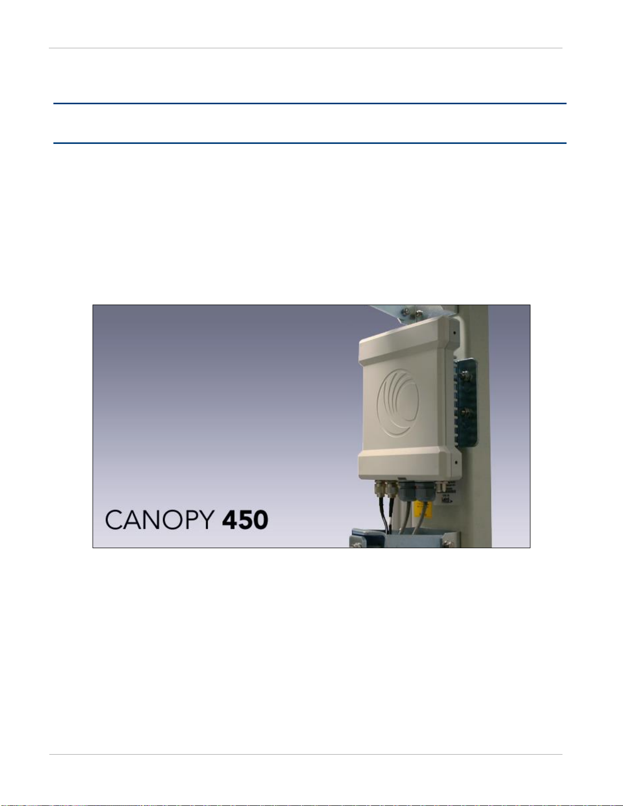
PMP 450 Planning Guide
System Release 12.1.1
For Regulatory Review Only

pmp-0047 (June 2013)
PMP 450 module essential information
Default IP Address for Management GUI Access
169.254.1.1
Default Administrator Username
admin
Default Administrator Password
(no password)
Software Upgrade Procedure
See “Updating the software version and using
CNUT” in the PMP 450 Configuration and User
Guide
Resetting to Factory Defaults (2 options)
1. On the radio GUI, navigate to Configuration,
Unit Settings and select Set to Factory
Defaults
OR
2. On the radio GUI, navigate to Configuration,
Unit Settings and enable and save option Set to
Factory Defaults Upon Default Plug
Detection. When the unit is powered on with a
default/override plug (see section “Acquiring the
Override Plug” in the PMP 450 Configuration
and User Guide) the radio will be returned to its
factory default settings.

pmp-0047 (June 2013)
Accuracy
While reasonable efforts have been made to assure the accuracy of this document, Cambium Networks assumes no
liability resulting from any inaccuracies or omissions in this document, or from use of the information obtained herein.
Cambium reserves the right to make changes to any products described herein to improve reliability, function, or design,
and reserves the right to revise this document and to make changes from time to time in content hereof with no obligation
to notify any person of revisions or changes. Cambium does not assume any liability arising out of the application or use
of any product, software, or circuit described herein; neither does it convey license under its patent rights or the rights of
others. It is possible that this publication may contain references to, or information about Cambium products (machines
and programs), programming, or services that are not announced in your country. Such references or information must not
be construed to mean that Cambium intends to announce such Cambium products, programming, or services in your
country.
Copyrights
This document, Cambium products, and 3rd Party Software products described in this document may include or describe
copyrighted Cambium and other 3rd Party supplied computer programs stored in semiconductor memories or other media.
Laws in the United States and other countries preserve for Cambium, its licensors, and other 3rd Party supplied software
certain exclusive rights for copyrighted material, including the exclusive right to copy, reproduce in any form, distribute
and make derivative works of the copyrighted material. Accordingly, any copyrighted material of Cambium, its licensors,
or the 3rd Party software supplied material contained in the Cambium products described in this document may not be
copied, reproduced, reverse engineered, distributed, merged or modified in any manner without the express written
permission of Cambium. Furthermore, the purchase of Cambium products shall not be deemed to grant either directly or
by implication, estoppel, or otherwise, any license under the copyrights, patents or patent applications of Cambium or
other 3rd Party supplied software, except for the normal non-exclusive, royalty free license to use that arises by operation
of law in the sale of a product.
Restrictions
Software and documentation are copyrighted materials. Making unauthorized copies is prohibited by law. No part of the
software or documentation may be reproduced, transmitted, transcribed, stored in a retrieval system, or translated into any
language or computer language, in any form or by any means, without prior written permission of Cambium.
License Agreements
The software described in this document is the property of Cambium and its licensors. It is furnished by express license
agreement only and may be used only in accordance with the terms of such an agreement.
High Risk Materials
Components, units, or 3rd Party products used in the product described herein are NOT fault-tolerant and are NOT
designed, manufactured, or intended for use as on-line control equipment in the following hazardous environments
requiring fail-safe controls: the operation of Nuclear Facilities, Aircraft Navigation or Aircraft Communication Systems,
Air Traffic Control, Life Support, or Weapons Systems (High Risk Activities). Cambium and its supplier(s) specifically
disclaim any expressed or implied warranty of fitness for such High Risk Activities.
© 2013 Cambium Networks, Inc. All Rights Reserved.


PMP 450 Planning Guide
Safety and regulatory information
pmp-0047 (June 2013)
i
Safety and regulatory information
This section describes important safety and regulatory guidelines that must be observed by personnel installing or
operating PMP 450 equipment.
Important safety information
To prevent loss of life or physical injury, observe the safety guidelines in this section.
Power lines
Exercise extreme care when working near power lines.
Working at heights
Exercise extreme care when working at heights.
Grounding and protective earth
PMP 450 units must be properly grounded to protect against lightning. It is the user’s responsibility to install the
equipment in accordance with national regulations. In the USA, follow Section 810 of the National Electric Code,
ANSI/NFPA No.70-1984 (USA). In Canada, follow Section 54 of the Canadian Electrical Code. These codes
describe correct installation procedures for grounding the outdoor unit, mast, lead-in wire and discharge unit, size of
grounding conductors and connection requirements for grounding electrodes. Other regulations may apply in
different countries and therefore it is recommended that installation of the outdoor unit be contracted to a
professional installer.
Powering down before servicing
Always power down and unplug the equipment before servicing.
Primary disconnect device
The AP or SM unit’s power supply is the primary disconnect device.
External cables
Safety may be compromised if outdoor rated cables are not used for connections that will be exposed to the outdoor
environment.

Safety and regulatory information
PMP 450 Planning Guide
ii
pmp-0047 (June 2013)
RF exposure near the antenna
Radio frequency (RF) fields will be present close to the antenna when the transmitter is on. Always turn off the
power to the PMP 450 unit before undertaking maintenance activities in front of the antenna.
Minimum separation distances
Install the AP/SM so as to provide and maintain the minimum separation distances from all persons.
The minimum separation distances for each frequency variant are specified in Calculated distances and power
compliance margins on page 4-12.
Important regulatory information
The PMP 450 product is certified as an unlicensed device in frequency bands where it is not allowed to cause
interference to licensed services (called primary users of the bands).
Radar avoidance
In countries where radar systems are the primary band users, the regulators have mandated special requirements to
protect these systems from interference caused by unlicensed devices. Unlicensed devices must detect and avoid
co-channel operation with radar systems.
Installers and users must meet all local regulatory requirements for radar detection. To meet these requirements,
users must set the correct Country Code during commissioning of the PMP 450. If this is not done, installers and
users may be liable to civil and criminal penalties.
Contact the Cambium helpdesk if more guidance is required.
USA and Canada specific information
The USA Federal Communications Commission (FCC) has asked manufacturers to implement special features to
prevent interference to radar systems that operate in the 5250-5350 and 5470-5725 MHz bands. These features must
be implemented in all products able to operate outdoors in the UNII band. The use of the 5600 – 5650 MHz band is
prohibited, even with detect-and-avoid functionality implemented.
Manufacturers must ensure that such radio products cannot be configured to operate outside of FCC rules;
specifically it must not be possible to disable or modify the radar protection functions that have been demonstrated
to the FCC.
In order to comply with these FCC requirements, Cambium supplies variants of the PMP 450 for operation in the
USA or Canada. These variants are only allowed to operate with Country Codes that comply with FCC/IC rule.

PMP 450 Planning Guide
Contents
pmp-0047 (June 2013)
iii
Contents
PMP 450 module essential information ............................................................................................................................... 2
Safety and regulatory information .................................................................................... i
Important safety information ......................................................................................................................................... i
Important regulatory information ................................................................................................................................. ii
About This Planning Guide ................................................................................................ x
General information ............................................................................................................................................................ xi
Version information .................................................................................................................................................... xi
Contacting Cambium Networks .................................................................................................................................. xi
Chapter 1: Product description .................................................................................. 1-1
Overview of PMP 450 ......................................................................................................................................................1-2
Purpose ................................................................ ................................ ................................................................ ......1-2
Key features ...............................................................................................................................................................1-2
Typical deployment ...................................................................................................................................................1-3
System components ...................................................................................................................................................1-4
Access Point (AP) .............................................................................................................................................................1-5
Network connection ..................................................................................................................................................1-8
AP power supply .......................................................................................................................................................1-8
Further reading on the AP .........................................................................................................................................1-8
Subscriber Module (SM) ...................................................................................................................................................1-9
Mounting brackets ................................................................................................ ................................ ...................1-12
Network connection ................................................................................................................................................1-12
SM power supply.....................................................................................................................................................1-12
Further reading on the SM .......................................................................................................................................1-13
Cabling and lightning protection .....................................................................................................................................1-14
PMP and lightning protection ..................................................................................................................................1-14
Outdoor connections ................................................................................................................................................1-14
Wireless operation ..........................................................................................................................................................1-15
Time division duplexing ..........................................................................................................................................1-15
OFDM and channel bandwidth ...............................................................................................................................1-15
Link operation – Dynamic Rate Adapt ....................................................................................................................1-16
Adaptive modulation ...............................................................................................................................................1-20
MIMO......................................................................................................................................................................1-20
Cyclic Prefix ............................................................................................................................................................1-20
Encryption ...............................................................................................................................................................1-21
Further reading on wireless operation .....................................................................................................................1-21
System management .......................................................................................................................................................1-22
Management agent ..................................................................................................................................................1-22
Web server ...............................................................................................................................................................1-22

Contents
PMP 450 Planning Guide
iv
pmp-0047 (June 2013)
Remote Authentication Dial In User Service (RADIUS) ....................................................................................... 1-25
SNMP ..................................................................................................................................................................... 1-25
Network Time Protocol (NTP) ............................................................................................................................... 1-26
Wireless Manager (WM) ........................................................................................................................................ 1-26
Capacity upgrades .................................................................................................................................................. 1-28
Software upgrade .................................................................................................................................................... 1-28
Further reading on system management ................................................................................................................. 1-28
Chapter 2: Planning considerations ........................................................................... 2-1
Regulatory planning ......................................................................................................................................................... 2-2
Obeying Regulatory limits........................................................................................................................................ 2-2
Conforming to the limits........................................................................................................................................... 2-2
Network migration planning ............................................................................................................................................ 2-3
Example PMP 450 deployment scenario .................................................................................................................. 2-3
Sector capacity.......................................................................................................................................................... 2-5
Site planning .................................................................................................................................................................. 2-11
AP or SM site selection .......................................................................................................................................... 2-11
Power supply site selection..................................................................................................................................... 2-11
Maximum cable lengths.......................................................................................................................................... 2-11
Wind loading .......................................................................................................................................................... 2-12
Link planning ................................................................................................................................................................. 2-14
Range and obstacles ............................................................................................................................................... 2-14
Path loss considerations .......................................................................................................................................... 2-18
Calculating maximum power level for connectorized AP units ............................................................................. 2-18
Understanding Attenuation ..................................................................................................................................... 2-19
Calculating Link Loss ............................................................................................................................................. 2-19
Calculating Rx Signal Level ................................................................................................................................... 2-19
Calculating Fade Margin ........................................................................................................................................ 2-20
Analyzing the RF Environment ..................................................................................................................................... 2-20
Mapping RF Neighbor Frequencies........................................................................................................................ 2-20
Analyzing the spectrum .......................................................................................................................................... 2-21
Anticipating Reflection of Radio Waves ................................................................................................................ 2-22
Noting Possible Obstructions in the Fresnel Zone ................................ ................................................................ .. 2-22
Multiple OFDM Access Point Clusters .................................................................................................................. 2-23
Planning for co-location and using the OFDM Frame Calculator Tool.................................................................. 2-25
Selecting Sites for Network Elements ............................................................................................................................ 2-28
Surveying Sites ....................................................................................................................................................... 2-29
Clearing the Radio Horizon .................................................................................................................................... 2-29
Calculating the Aim Angles ................................................................................................................................... 2-30
Diagramming Network Layouts ..................................................................................................................................... 2-31
Avoiding Self Interference ..................................................................................................................................... 2-31
Avoiding Other Interference ................................................................................................................................... 2-32
Grounding and lightning protection ............................................................................................................................... 2-33
The need for power surge protection ...................................................................................................................... 2-33
Standards ................................................................................................................................................................ 2-33

PMP 450 Planning Guide
Contents
pmp-0047 (June 2013)
v
Lightning protection zones ......................................................................................................................................2-34
General protection requirements .............................................................................................................................2-35
Protection requirements for a mast or tower installation .........................................................................................2-37
Protection requirements for a wall installation ........................................................................................................2-38
Protection requirements on a high rise building ......................................................................................................2-39
Configuration options for TDD synchronization ............................................................................................................2-41
GPS synchronization ...............................................................................................................................................2-41
Mounting the GPS receiver (CMM or UGPS) module on the equipment building ................................ .................2-43
Mounting the GPS receiver (CMM or UGPS) module on a metal tower or mast ...................................................2-43
Data network planning ....................................................................................................................................................2-44
Understanding addresses .........................................................................................................................................2-44
Dynamic or static addressing ...................................................................................................................................2-44
DNS Client ..............................................................................................................................................................2-45
Network Address Translation (NAT) ......................................................................................................................2-45
Developing an IP addressing scheme ......................................................................................................................2-46
Address Resolution Protocol ...................................................................................................................................2-46
Allocating subnets ...................................................................................................................................................2-47
Selecting non-routable IP addresses ........................................................................................................................2-47
Translation bridging ................................................................................................................................................2-48
Engineering VLANs ................................................................................................................................................2-48
Security planning ............................................................................................................................................................2-52
Isolating APs from the Internet ...............................................................................................................................2-52
Managing module access by passwords ..................................................................................................................2-52
Filtering protocols and ports ....................................................................................................................................2-56
Port Lockdown ........................................................................................................................................................2-60
Isolating SMs ...........................................................................................................................................................2-60
Filtering management through Ethernet ..................................................................................................................2-61
Allowing management from only specified IP addresses ........................................................................................2-61
Configuring management IP by DHCP ...................................................................................................................2-61
Planning for airlink security ....................................................................................................................................2-61
Planning for RF Telnet Access Control ...................................................................................................................2-62
Forwarding Downlink PPPoE PADI packets ..........................................................................................................2-62
Planning for RADIUS integration ...........................................................................................................................2-62
Planning for SNMP security ....................................................................................................................................2-63
Ordering components ......................................................................................................................................................2-64
PMP 450 component part numbers .........................................................................................................................2-64
Chapter 3: Legal information ..................................................................................... 3-1
Cambium Networks end user license agreement ..............................................................................................................3-2
Acceptance of this agreement ....................................................................................................................................3-2
Definitions .................................................................................................................................................................3-2
Grant of license .........................................................................................................................................................3-2
Conditions of use .......................................................................................................................................................3-2
Title and restrictions ..................................................................................................................................................3-3
Confidentiality ...........................................................................................................................................................3-4

Contents
PMP 450 Planning Guide
vi
pmp-0047 (June 2013)
Right to use Cambium’s name .................................................................................................................................. 3-4
Transfer .................................................................................................................................................................... 3-4
Updates ..................................................................................................................................................................... 3-4
Maintenance ............................................................................................................................................................. 3-5
Disclaimer ................................................................................................................................................................ 3-5
Limitation of liability ............................................................................................................................................... 3-5
U.S. government ....................................................................................................................................................... 3-6
Term of license ......................................................................................................................................................... 3-6
Governing law .......................................................................................................................................................... 3-6
Assignment ............................................................................................................................................................... 3-6
Survival of provisions ............................................................................................................................................... 3-6
Entire agreement ....................................................................................................................................................... 3-7
Third party software ................................................................................................................................................. 3-7
Hardware warranty ........................................................................................................................................................... 3-9
Limit of liability ................................ ................................................................ ............................................................. 3-10
Chapter 4: Reference information .............................................................................. 4-1
Equipment specifications ................................................................................................................................................. 4-2
AP specifications ...................................................................................................................................................... 4-2
SM specifications ..................................................................................................................................................... 4-5
Wireless specifications ..................................................................................................................................................... 4-8
General wireless specifications................................................................................................................................. 4-8
Data network specifications ............................................................................................................................................. 4-9
Ethernet interface...................................................................................................................................................... 4-9
Compliance with safety standards .................................................................................................................................. 4-10
Electrical safety compliance ................................................................................................................................... 4-10
Electromagnetic compatibility (EMC) compliance ................................................................................................ 4-10
Human exposure to radio frequency energy ........................................................................................................... 4-11
Compliance with radio regulations ................................................................................................................................ 4-15
Type approvals ....................................................................................................................................................... 4-15
DFS for 5.4 GHz Radios......................................................................................................................................... 4-16
Country Codes and available spectrum .................................................................................................................. 4-19
FCC compliance testing ......................................................................................................................................... 4-29
FCC and ICC IDs and certification numbers .......................................................................................................... 4-29
Notifications ................................................................................................................................................................... 4-33
PMP 450 regulatory compliance ............................................................................................................................ 4-33
Appendix A: Glossary ..................................................................................................... I

PMP 450 Planning Guide
List of Figures
pmp-0047 (June 2013)
vii
List of Figures
Figure 1 Line Of Sight Diagram .............................................................................................................................................1-3
Figure 2 AP, Radio unit ..........................................................................................................................................................1-5
Figure 3 AP, antenna ..............................................................................................................................................................1-5
Figure 4 AP interfaces ............................................................................................................................................................1-6
Figure 5 AP diagnostic LEDs, viewed from unit front ...........................................................................................................1-7
Figure 6 PMP 450 Series SM .................................................................................................................................................1-9
Figure 7 SM interfaces ..........................................................................................................................................................1-10
Figure 8 SM diagnostic LEDs, viewed from unit front ........................................................................................................1-11
Figure 9 TDD frame division................................................................................................................................................1-15
Figure 10 AP web-based management screenshot ................................................................................................................1-23
Figure 11 Determinants in Rx signal level ............................................................................................................................2-19
Figure 12 Example layout of 16 Access Point sectors (ABCD), 90 degree sectors ..............................................................2-23
Figure 13 Example layout of 16 Access Point sectors (ABC), 60 degree sectors.................................................................2-24
Figure 14 OFDM Frame Calculator tab ................................................................................................................................2-26
Figure 15 Variables for calculating angle of elevation (and depression) ..............................................................................2-30
Figure 16 Rolling sphere method to determine the lightning protection zones ....................................................................2-34
Figure 17 Grounding cable minimum bend radius and angle ...............................................................................................2-36
Figure 18 Grounding and lightning protection on mast or tower ..........................................................................................2-37
Figure 19 Grounding and lightning protection on wall .........................................................................................................2-38
Figure 20 Grounding and lightning protection on building ..................................................................................................2-39
Figure 21 Grounding and lightning protection inside high building .....................................................................................2-40
Figure 22 One unsynchronized AP in cluster resulting in self-interference .........................................................................2-42
Figure 23 GPS timing throughout the network .....................................................................................................................2-43
Figure 24 Cambium network management domain ..............................................................................................................2-45
Figure 25 Example of IP address in Class B subnet ..............................................................................................................2-47
Figure 26 Categorical protocol filtering ...............................................................................................................................2-58
Figure 27 AP DFS Status ......................................................................................................................................................4-16

List of Tables
PMP 450 Planning Guide
viii
pmp-0047 (June 2013)
List of Tables
Table 1 PMP 450 frequency variants ..................................................................................................................................... 1-4
Table 2 AP interface descriptions and cabling ....................................................................................................................... 1-7
Table 3 AP LED descriptions ................................................................................................................................................ 1-8
Table 4 SM Interfaces .......................................................................................................................................................... 1-10
Table 5 SM diagnostic LED descriptions ............................................................................................................................ 1-12
Table 6 Link Budget Details – Dynamic Rate Adapt, 2.4 GHz Variant .............................................................................. 1-16
Table 7 Link Budget Details – Dynamic Rate Adapt, 5.4 GHz / 5.8 GHz Variant .............................................................. 1-18
Table 8 Deployment scenario terminology descriptions ........................................................................................................ 2-3
Table 9 Examples of aggregate sector throughput – various air interfaces ............................................................................ 2-5
Table 10 Deployment scenario 1 ........................................................................................................................................... 2-6
Table 11 Scenario 1 spectrum usage ...................................................................................................................................... 2-7
Table 12 Deployment scenario 2 ........................................................................................................................................... 2-9
Table 13 Deployment scenario 2 spectrum usage ................................................................................................................ 2-10
Table 14 Sync cable length specification ............................................................................................................................. 2-12
Table 15 Lateral force - metric ............................................................................................................................................ 2-12
Table 16 Lateral force - US ................................................................................................................................................. 2-13
Table 17 Link budget details – PMP 450 link, 20 MHz Channel Bandwidth ....................................................................... 2-14
Table 18 Link budget details – PMP 450 link, 10 MHz Channel Bandwidth ....................................................................... 2-15
Table 19 Link budget details – PMP 450 link, 5MHz Channel Bandwidth .......................................................................... 2-16
Table 20 Example 5.8-GHz OFDM channel assignment by sector ..................................................................................... 2-23
Table 21 Example 5.8-GHz OFDM channel assignment by sector ..................................................................................... 2-24
Table 22 OFDM Frame Calculator tab attributes ................................................................................................................ 2-26
Table 23 OFDM Calculated Frame Results attributes ......................................................................................................... 2-27
Table 24 Special case VLAN IDs ........................................................................................................................................ 2-49
Table 25 VLAN filters in point-to-multipoint modules ....................................................................................................... 2-49
Table 26 Q-in-Q Ethernet frame .......................................................................................................................................... 2-50
Table 27 Identity-based user account permissions - AP ...................................................................................................... 2-53
Table 28 Identity-based user account permissions - SM...................................................................................................... 2-55
Table 29 Ports filtered per protocol selections ..................................................................................................................... 2-59
Table 30 Device default port numbers ................................................................................................................................. 2-60
Table 31 PMP 450 components ........................................................................................................................................... 2-64
Table 32 Connectorized AP physical specifications ............................................................................................................... 4-2
Table 33 SM physical specifications ...................................................................................................................................... 4-5
Table 34 PMP 450 wireless specifications ............................................................................................................................ 4-8
Table 35 PMP 450 Ethernet bridging specifications .............................................................................................................. 4-9
Table 36 PMP 450 safety compliance specifications ........................................................................................................... 4-10
Table 37 EMC emissions compliance .................................................................................................................................. 4-10
Table 38 Power Compliance Margins .................................................................................................................................. 4-13
Table 39 Radio certifications ............................................................................................................................................... 4-15

PMP 450 Planning Guide
List of Tables
pmp-0047 (June 2013)
ix
Table 40 OFDM DFS operation based on Country Code setting .........................................................................................4-18
Table 41 Center channel details based on Country Code, 2.4-GHz ......................................................................................4-20
Table 42 Center channel details based on Country Code, 5.4-GHz ......................................................................................4-21
Table 43 Center channel details based on Country Code, 5.8-GHz ......................................................................................4-21
Table 44 AP Default combined transmit power per Country Code – 2.4-GHz band ............................................................4-23
Table 45 Default combined transmit power per Country Code – 5.4-GHz band ..................................................................4-25
Table 46 Default combined transmit power per Country Code – 5.8-GHz band ..................................................................4-26
Table 47 US FCC IDs and Industry Canada Certification Numbers and Covered Configurations ......................................4-29
Table 48 Industry Canada approved antenna list ..................................................................................................................4-34
Table 49 Glossary ...................................................................................................................................................................... I
PMP 450 Planning Guide
About This Planning Guide
x
pmp-0047 (June 2013)
About This Planning Guide
This guide describes the planning of the Cambium PMP 450 Series of point-to-multipoint wireless equipment
deployment. It is intended for use by the system designer.
The guide consists of the following chapters:
Chapter 1: Product description on page on page 1-1
Chapter 2: Planning considerations on page 2-1
Chapter 3: Legal information on page 3-1
Chapter 4: Reference information on page 4-1

General information
PMP 450 Planning Guide
pmp-0047 (June 2013)
xi
Issue
Date of issue
Remarks
001v000
September 2012
System Release 12.0
002v000
October 2012
Includes additional co-location information
003v000
November 2012
Updated for System Release 12.0.1
004v000
January 2013
Updated for System Release 12.0.2
005v000
March 2013
Updated for System Release 12.0.3/12.0.3.1
Includes additional performance details (SNR)
006v000
June 2013
Updated for System Release 12.1
General information
Version information
The following shows the issue status of this document since it was first released:
Contacting Cambium Networks
PMP support website: http://www.cambiumnetworks.com/support
Cambium main website: http://www.cambiumnetworks.com/
Sales enquiries: solutions@cambiumnetworks.com
Email support: support@cambiumnetworks.com
Telephone numbers:
For full list of Cambium support telephone numbers, see:
http://www.cambiumnetworks.com/support/technical.php
Address:
Cambium Networks
3800 Golf Road, Suite 360
Rolling Meadows, IL 60008

PMP 450 Planning Guide
About This Planning Guide
xii
pmp-0047 (June 2013)
Purpose
Cambium Networks Point-To-Multipoint (PMP) documents are intended to instruct and assist personnel in the
operation, installation and maintenance of the Cambium PMP equipment and ancillary devices. It is recommended
that all personnel engaged in such activities be properly trained.
Cambium disclaims all liability whatsoever, implied or express, for any risk of damage, loss or reduction in system
performance arising directly or indirectly out of the failure of the customer, or anyone acting on the customer's
behalf, to abide by the instructions, system parameters, or recommendations made in this document.
Cross references
References to external publications are shown in italics. Other cross references, emphasized in blue text in
electronic versions, are active links to the references.
This document is divided into numbered chapters that are divided into sections. Sections are not numbered, but are
individually named at the top of each page, and are listed in the table of contents.
Feedback
We appreciate feedback from the users of our documents. This includes feedback on the structure, content,
accuracy, or completeness of our documents. Send feedback to email support (see ‘Contacting Cambium
Networks’).

Problems and warranty
PMP 450 Planning Guide
pmp-0047 (June 2013)
xiii
1
Search this document and the software release notes of supported releases.
2
Visit the support website. http://www.cambiumnetworks.com/support/pmp/software/index.php
3
Ask for assistance from the Cambium product supplier.
4
Gather information from affected units such as:
The IP addresses and MAC addresses.
The software releases.
The configuration of software features.
Any available diagnostic downloads.
CNUT Support Capture Tool information
5
Escalate the problem by emailing or telephoning support.
Problems and warranty
Reporting problems
If any problems are encountered when installing or operating this equipment, follow this procedure to investigate
and report:
See ‘Contacting Cambium Networks’ for URLs, email addresses and telephone numbers.
Repair and service
If unit failure is suspected, obtain details of the Return Material Authorization (RMA) process from the support
website.
Warranty
Cambium’s standard hardware warranty is for one (1) year from date of shipment from Cambium or a Cambium
distributor. Cambium warrants that hardware will conform to the relevant published specifications and will be free
from material defects in material and workmanship under normal use and service. Cambium shall within this time,
at its own option, either repair or replace the defective product within thirty (30) days of receipt of the defective
product. Repaired or replaced product will be subject to the original warranty period but not less than thirty (30)
days.
To register PMP products or activate warranties, visit the support website.
Extended warranties are available for PMP products. For warranty assistance, contact the reseller or distributor.
Using non-Cambium parts for repair could damage the equipment or void warranty. Contact Cambium for service
and repair instructions.

PMP 450 Planning Guide
About This Planning Guide
xiv
pmp-0047 (June 2013)
Portions of Cambium equipment may be damaged from exposure to electrostatic discharge. Use precautions to
prevent damage.

Security advice
PMP 450 Planning Guide
pmp-0047 (June 2013)
xv
Security advice
Cambium Networks systems and equipment provide security parameters that can be configured by the operator
based on their particular operating environment. Cambium recommends setting and using these parameters
following industry recognized security practices. Security aspects to be considered are protecting the
confidentiality, integrity, and availability of information and assets. Assets include the ability to communicate,
information about the nature of the communications, and information about the parties involved.
In certain instances Cambium makes specific recommendations regarding security practices, however the
implementation of these recommendations and final responsibility for the security of the system lies with the
operator of the system.

PMP 450 Planning Guide
About This Planning Guide
xvi
pmp-0047 (June 2013)
Warnings, cautions, and notes
The following describes how warnings and cautions are used in this document and in all documents of the
Cambium Networks document set.
Warnings
Warnings precede instructions that contain potentially hazardous situations. Warnings are used to alert the reader to
possible hazards that could cause loss of life or physical injury. A warning has the following format:
Warning text and consequence for not following the instructions in the warning.
Cautions
Cautions precede instructions and are used when there is a possibility of damage to systems, software, or individual
items of equipment within a system. However, this damage presents no danger to personnel. A caution has the
following format:
Notes
A note means that there is a possibility of an undesirable situation or provides additional information to help the
reader understand a topic or concept. A note has the following format:
Caution text and consequence for not following the instructions in the caution.
Note text.

PMP 450 Planning Guide
Product description
pmp-0047 (June 2013)
1-1
Chapter 1: Product description
This chapter provides a high level description of the PMP 450 product. It describes in general terms the function of
the product, the main product variants and typical deployment. It also describes the main hardware components.
The chapter consists of the following topics:
Overview of PMP 450 on page 1-2: Introduces the key features, typical uses, product variants and components
of the PMP 450.
Access Point (AP) on page 1-5: Describes the AP and its interfaces
Subscriber Module (SM) on page 1-9: Describes the SM and its interfaces
Cabling and lightning protection on page 1-14: Describes the cabling and lightning protection components of a
PMP 450 installation.
Wireless operation on page 1-15: Describes how the PMP 450 wireless link is operated, including modulation
modes, power control and security.
System management on page 1-22: Introduces the PMP 450 management system, including the web interface,
installation, configuration, alerts and upgrades.

Overview of PMP 450
Product description
1-2
pmp-0047 (June 2013)
Overview of PMP 450
This section introduces the key features, typical uses, product variants and components of the PMP 450.
Purpose
Cambium PMP 450 Series networks are designed for wireless point-to-multipoint links in the unlicensed 2.4 GHz,
5.4 GHz, and 5.8 GHz bands. Users must ensure that the PMP 450 Series complies with local operating
regulations.
The PMP 450 Series adds dramatically increased network throughput and capacity. The PMP 450 Series enables
network operators to grow their business by offering more capacity for data, voice and video applications.
Key features
The Cambium PMP 450 Series offers the following benefits:
Cambium’s highest performing point-to-multipoint solution, with up to 90 Mbps usable throughput
State-of-the-art MIMO (Multi-In Multi-Out) technology
Better spectral efficiency than other MIMO alternatives
Efficient GPS synchronized, scheduled TDD operation for easy Access Point site deployment and performance
that is consistent regardless of subscriber loading
A range of cost-effective subscriber device solutions to meet the business case of any network application
MIMO Matrix B: This technique provides for the ability to double the throughput of a radio transmission under
proper RF conditions. Different data streams are transmitted simultaneously on two different antennas.
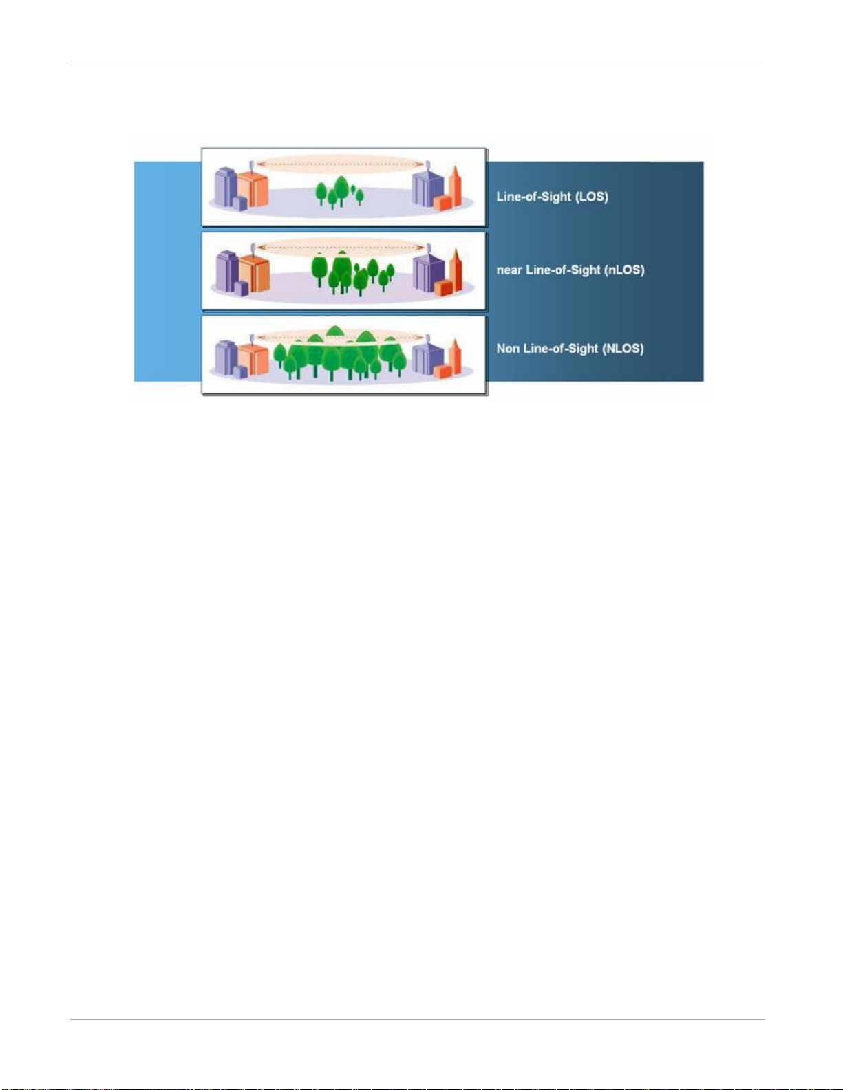
nLOS benefits and limitations
In addition to providing LOS (Line-Of-Sight) connectivity, use of OFDM technology can provide nLOS (near Line-
Of-Sight) connectivity and sometimes NLOS (Non-Line-Of-Sight) connectivity:
LOS: the installer can see the AP from the SM and the first Fresnel zone is clear.
nLOS: the installer can see the AP from the SM, but a portion of the first Fresnel zone is blocked.
NLOS: the installer cannot see the AP from the SM and a portion or even much of the first Fresnel zone is
blocked, but subsequent Fresnel zones are open.
PMP 450 Planning Guide
Overview of PMP 450
pmp-0047 (June 2013)
1-3
Figure 1 Line Of Sight Diagram
Whereas multi-pathing degrades a link in some technologies (FSK, for example), OFDM can often use multipathing to an advantage to overcome nLOS, especially in cases where the Fresnel zone is only partially blocked by
buildings, “urban canyons”, or foliage. OFDM tends to help especially when obstacles are near the middle of the
link, and less so when the obstacles are very near the SM or AP.
However, attenuation through walls and trees is substantial for any use of the 2.4/5.4/5.8 GHz frequency bands.
Even with OFDM, these products should not be expected to penetrate walls or extensive trees and foliage.
Typical deployment
The PMP 450 Series consists of Access Point Modules and Subscriber Modules. The radio link operates on a single
frequency channel in each direction using Time Division Duplex (TDD).
Applications for the PMP 450 Series include:
High throughput enterprise applications
nLOS video surveillance in metro areas
Urban area network extension
Network extension into areas with foliage
Greenfield deployment
The PMP 450 Series equipment may be deployed as a standalone network deployment offering a high-speed access
network.

Overview of PMP 450
Product description
1-4
pmp-0047 (June 2013)
Variant
Region
Frequency
Coverage
(MHz)
Channel
Bandwidth
(MHz)
Variant
Notes
2.4 GHz
PMP 450
FCC ISM Band
2400 – 2483.5
5/10/20
5.4/5.8GHz
PMP 450
FCC UNII Band
ETSI Band B
ETSI Band C
5470 - 5875
10/20
Combined
Transmit power
limited based on
Country Code
setting
5.8-GHz
PMP 450
(US
ONLY)
FCC ISM Band
5725 - 5875
5/10/20
US Only –
locked to US
Country Code
EIRP limit of 36
dBm and 5.8GHz Only
System components
PMP 450 Access Point
Access Point Module (AP): A connectorized outdoor transceiver unit containing all the radio, networking,
antenna, and surge suppression electronics.
Access Point Power Supply: An indoor power supply module providing Power-over-Ethernet (PoE) supply to
the Access Point.
Cabling: Cat 5e cables, grounding cables, and connectors.
PMP 450 Subscriber Module
Subscriber Module (SM): An integrated-antenna outdoor transceiver unit containing all the radio, antenna,
and networking electronics.
Subscriber Module Power Supply: An indoor power supply module providing Power-over-Ethernet (PoE)
supply to the Subscriber Module.
Cabling and lightning protection: Cat 5e cables, grounding cables, connectors and lightning protection (surge
suppression).
Product variants
The PMP 450 Series is available in the following product variants:
Table 1 PMP 450 frequency variants
PMP 450 Planning Guide
Access Point (AP)
pmp-0047 (June 2013)
1-5
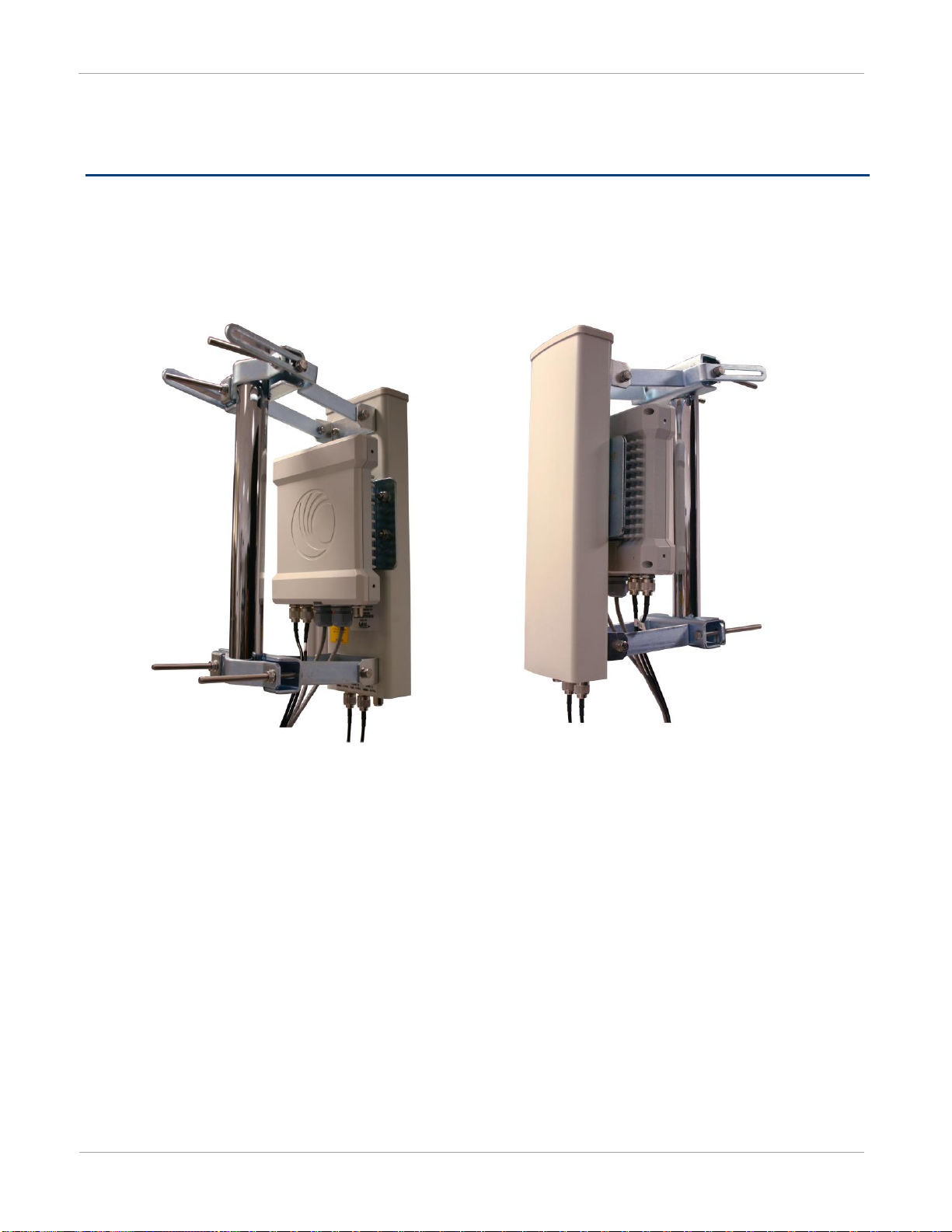
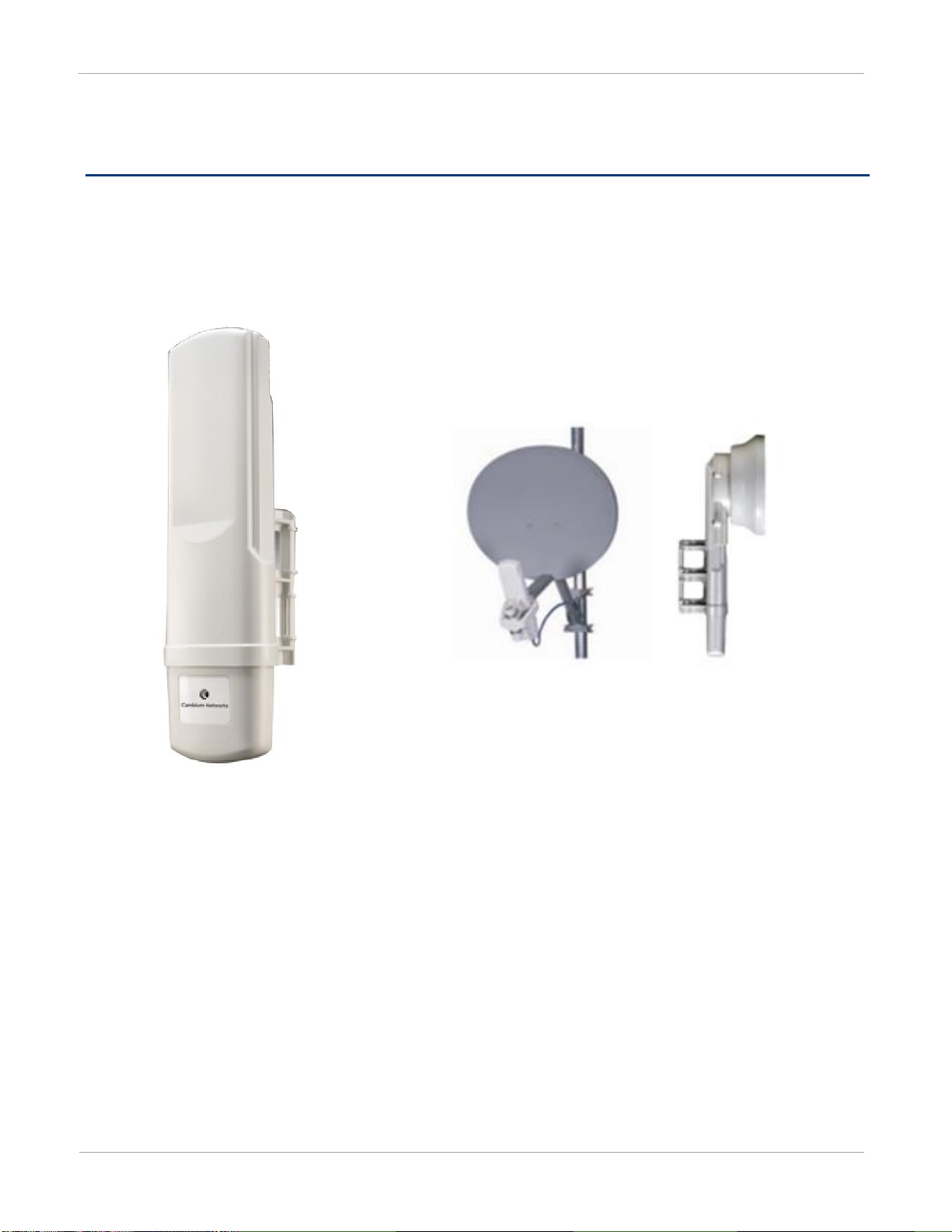
Figure 2 AP, Radio unit
Figure 3 AP, antenna
Access Point (AP)
The AP is a self-contained unit that houses both radio and networking electronics. The AP is supplied in a
connectorized configuration for use with an external antenna. Connectorized units with external antennas can cope
with more difficult radio conditions.
Access Point (AP)
Product description
1-6
pmp-0047 (June 2013)
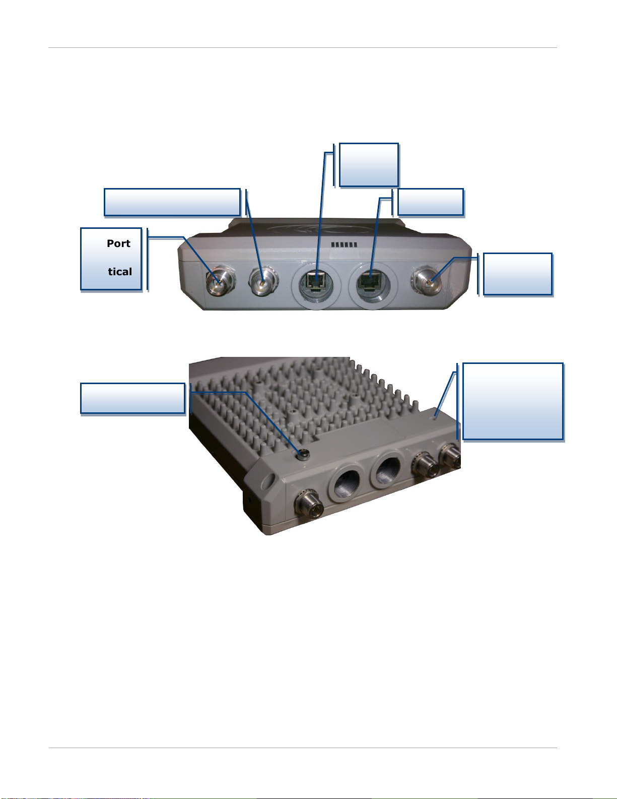
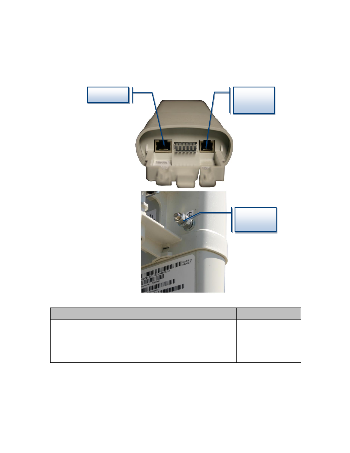
Vertical
RF Port – Horizontal
Default
Ethernet
– FSK
AP Ground Lug
AP interfaces
The AP interfaces are illustrated in Figure 4.
Figure 4 AP interfaces
RF Port
–
Sync /
RF Port
Equilibrium
Membrane
Vent (do not
cover)
PMP 450 Planning Guide
Access Point (AP)
pmp-0047 (June 2013)
1-7
Interface
Function
Cabling
RF Port – Vertical
Vertical RF connection to AP antenna
50 ohm RF cable, N-type
RF Port – Horizontal
Horizontal RF connection to AP
antenna
50 ohm RF cable, N-type
Sync/Default
GPS synchronization signaling,
provides power to uGPS module.
Default plug port.
RJ11 cable or default plug
Power-over-Ethernet, Ethernet
communications (management
and data)
RJ45 cable
Power-over-Ethernet, Ethernet
communications (management
and data)
RF Port – FSK
For future use
50 ohm RF cable, N-type
Ground Lug (bottom of unit)
For grounding the unit
10 AWG copper wire
PWR
SYN/1
SES/2
GPS/3
ACT/4
LNK/5
Table 2 AP interface descriptions and cabling
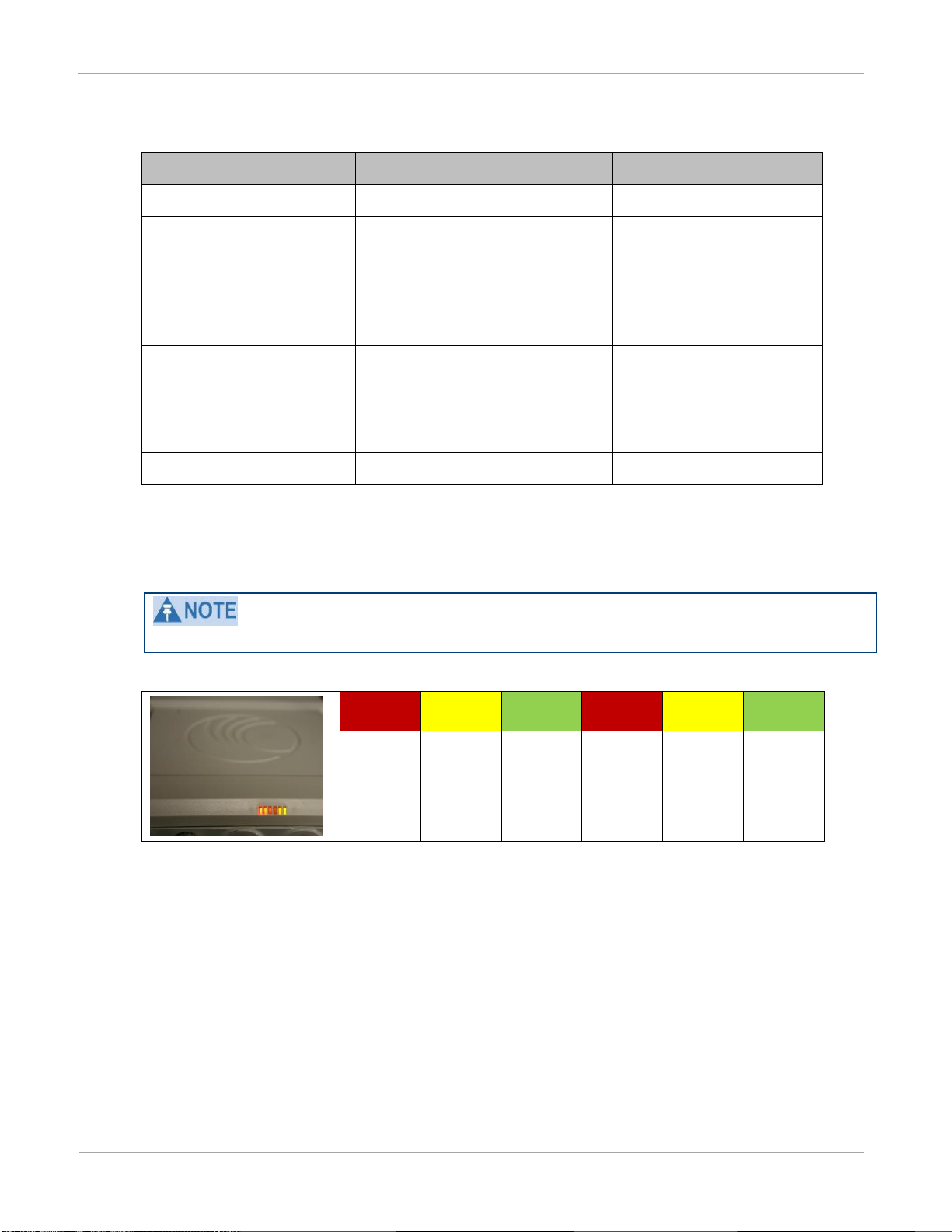
AP diagnostic LEDs
The diagnostic LEDs report the following information about the status of the module.
The LED color helps you distinguish position of the LED. The LED color does not indicate any status.
Figure 5 AP diagnostic LEDs, viewed from unit front

Access Point (AP)
Product description
1-8
pmp-0047 (June 2013)
LED
Color when active
Status
information
provided
Notes
PWR
red
DC power
Always lit when power is
correctly supplied.
SYN/1
yellow
Presence of sync
Always lit on the AP.
SES/2
green
Unused on the AP
GPS/3
red
Pulse of sync
Continuously lit as pulse as
AP receives pulse.
ACT/4
yellow
Presence of data
activity
on the Ethernet link
Flashes during data transfer.
Frequency of flash is not a
diagnostic indication.
LNK/5
green
Ethernet link
Continuously lit when link is
present.
Table 3 AP LED descriptions
Network connection
The network connection to a PMP 450 Series AP is made via a 10 BaseT, 100 BaseT, or 1000 BaseT Ethernet
connection. Power is provided to the AP over the Ethernet connection using a patented non-standard powering
technique.
AP power supply
The AP power supply generates the AP supply voltage (29 VDC) from the external DC source and injects the
supply voltage into the AP.
The power supply is connected to the AP and network equipment using Cat5e cable with RJ45 connectors. Refer to
Cabling and lightning protection on page 1-14.
Further reading on the AP
For more information on the AP, refer to the following:
AP or SM site selection on page 2-11 describes how to select a site for the AP or SM.
PMP 450 Planning Guide
Subscriber Module (SM)
pmp-0047 (June 2013)
1-9
Subscriber Module (SM)
The SM is a self-contained unit that houses both radio and networking electronics. The SM is supplied in an
integrated antenna configuration, but may also be used with a passive reflector dish or CLIP (Cassegrain Lens for
Improved Performance).
Figure 6 PMP 450 Series SM
Subscriber Module (SM)
Product description
1-10
pmp-0047 (June 2013)
Interface
Function
Cabling
Ethernet
Power-over-Ethernet, Ethernet
communications (management and data)
RJ45 Cable
Sync / Default
Default plug port.
RJ11 cable, default plug
Ground Lug (bottom of unit)
For grounding the unit
10 AWG copper wire
Ethernet
Lug
SM interfaces
Figure 7 SM interfaces
Sync /
Default
Ground
Table 4 SM Interfaces
 Loading...