

Page 1

F
Cambium PTP 700 Series User Guide
System Release 700-01-00
Page 2

Accuracy
Copyrights
Restrictions
License Agreements
High Risk Materials
While reasonable efforts have been made to assure the accuracy of this document, Cambium Networks
assumes no liability resulting from any inaccuracies or omissions in this document, or from use of the
information obtained herein. Cambium reserves the right to make changes to any products described
herein to improve reliability, function, or design, and reserves the right to revise this document and to
make changes from time to time in content hereof with no obligation to notify any person of revisions
or changes. Cambium does not assume any liability arising out of the application or use of any
product, software, or circuit described herein; neither does it convey license under its patent rights or
the rights of others. It is possible that this publication may contain references to, or information about
Cambium products (machines and programs), programming, or services that are not announced in
your country. Such references or information must not be construed to mean that Cambium intends to
announce such Cambium products, programming, or services in your country.
This document, Cambium products, and 3rd Party software products described in this document may
include or describe copyrighted Cambium and other 3
rd
Party supplied computer programs stored in
semiconductor memories or other media. Laws in the United States and other countries preserve for
rd
Cambium, its licensors, and other 3
Party supplied software certain exclusive rights for copyrighted
material, including the exclusive right to copy, reproduce in any form, distribute and make derivative
works of the copyrighted material. Accordingly, any copyrighted material of Cambium, its licensors, or
rd
Party software supplied material contained in the Cambium products described in this
the 3
document may not be copied, reproduced, reverse engineered, distributed, merged or modified in any
manner without the express written permission of Cambium. Furthermore, the purchase of Cambium
products shall not be deemed to grant either directly or by implication, estoppel, or otherwise, any
license under the copyrights, patents or patent applications of Cambium or other 3rd Party supplied
software, except for the normal non-exclusive, royalty free license to use that arises by operation of
law in the sale of a product.
Software and documentation are copyrighted materials. Making unauthorized copies is prohibited by
law. No part of the software or documentation may be reproduced, transmitted, transcribed, stored in a
retrieval system, or translated into any language or computer language, in any form or by any means,
without prior written permission of Cambium.
The software described in this document is the property of Cambium and its licensors. It is furnished
by express license agreement only and may be used only in accordance with the terms of such an
agreement.
Cambium and its supplier(s) specifically disclaim any express or implied warranty of fitness for any
high risk activities or uses of its products including, but not limited to, the operation of nuclear
facilities, aircraft navigation or aircraft communication systems, air traffic control, life support, or
weapons systems (“High Risk Use”). Any High Risk is unauthorized, is made at your own risk and you
shall be responsible for any and all losses, damage or claims arising out of any High Risk Use.
© 2015 Cambium Networks Limited. All Rights Reserved.
phn-4148_000v008 (May 2015)
Page 3

About This User Guide .......................................................................................................................... 1
Chapter 1: Product description ....................................................................................................... 1-1
Contents
Contacting Cambium Networks .................................................................................................... 1
Purpose ........................................................................................................................................... 2
Cross references ............................................................................................................................. 2
Feedback ......................................................................................................................................... 2
Important regulatory information........................................................................................................ 3
Radar avoidance ............................................................................................................................. 3
USA and Canada specific information ......................................................................................... 3
Renseignements specifiques aux USA et au Canada ................................................................. 4
EU Declaration of Conformity ....................................................................................................... 4
Application firmware ..................................................................................................................... 4
Specific expertise and training for professional installers ......................................................... 4
Avoidance of weather radars ........................................................................................................ 4
External antennas ........................................................................................................................... 5
Antennas externes ......................................................................................................................... 5
Ethernet networking skills ............................................................................................................. 5
Lightning protection ....................................................................................................................... 5
Training ........................................................................................................................................... 6
Problems and warranty ........................................................................................................................ 7
Reporting problems ....................................................................................................................... 7
Repair and service .......................................................................................................................... 7
Hardware warranty ........................................................................................................................ 7
Security advice ...................................................................................................................................... 8
Warnings, cautions, and notes ............................................................................................................ 9
Warnings ......................................................................................................................................... 9
Cautions .......................................................................................................................................... 9
Notes ............................................................................................................................................... 9
Caring for the environment ................................................................................................................ 10
In EU countries ............................................................................................................................. 10
In non-EU countries ..................................................................................................................... 10
Overview of the PTP 700 Series ........................................................................................................ 1-2
Purpose ........................................................................................................................................ 1-2
Key features ................................................................................................................................. 1-2
Frequency bands ......................................................................................................................... 1-3
Typical bridge deployment ........................................................................................................ 1-4
Hardware overview ..................................................................................................................... 1-5
Page i
Page 4

Contents
Wireless operation ............................................................................................................................. 1-6
Time division duplexing ............................................................................................................. 1-6
Link mode optimization .............................................................................................................. 1-8
Link symmetry ............................................................................................................................. 1-9
OFDM and channel bandwidth ................................................................................................ 1-10
Spectrum management ............................................................................................................ 1-11
Adaptive modulation ................................................................................................................ 1-12
MIMO .......................................................................................................................................... 1-13
Dynamic spectrum optimization .............................................................................................. 1-14
Radar avoidance ........................................................................................................................ 1-14
Encryption .................................................................................................................................. 1-15
License keys and regulatory bands ......................................................................................... 1-16
PTP networks ............................................................................................................................. 1-17
TDD synchronization (PTP-SYNC) ........................................................................................... 1-18
Ethernet bridging ............................................................................................................................. 1-21
Ethernet ports ............................................................................................................................ 1-21
Data and management services .............................................................................................. 1-21
Data network .............................................................................................................................. 1-23
Second Data network ................................................................................................................ 1-25
Out-of-Band Management Service .......................................................................................... 1-27
Ethernet loopback mode........................................................................................................... 1-29
Protocol model .......................................................................................................................... 1-30
Synchronous Ethernet .............................................................................................................. 1-31
IEEE 1588-2008 Transparent Clock .......................................................................................... 1-32
TDM bridging.................................................................................................................................... 1-34
TDM description ........................................................................................................................ 1-34
Lowest TDM modulation mode ............................................................................................... 1-35
Fixed frequency operation ....................................................................................................... 1-35
Ethernet cables for TDM ........................................................................................................... 1-36
Further reading .......................................................................................................................... 1-36
System management ....................................................................................................................... 1-37
Management agent ................................................................................................................... 1-37
Network management .............................................................................................................. 1-38
IPv6 ............................................................................................................................................. 1-40
Web server ................................................................................................................................. 1-41
RADIUS authentication ............................................................................................................. 1-43
SNMP.......................................................................................................................................... 1-44
Simple Network Time Protocol (SNTP) ................................................................................... 1-45
SNMPv3 security ....................................................................................................................... 1-46
System logging (syslog) ........................................................................................................... 1-49
AES license ................................................................................................................................ 1-49
Critical security parameters ..................................................................................................... 1-50
Software upgrade ...................................................................................................................... 1-51
Page ii
Page 5

Contents
Chapter 2: System hardware .......................................................................................................... 2-1
Capability upgrades .................................................................................................................. 1-52
Full capability trial period ......................................................................................................... 1-52
Recovery mode .......................................................................................................................... 1-53
FIPS 140-2 mode .............................................................................................................................. 1-54
FIPS 140-2 approved mode ...................................................................................................... 1-54
Exiting from the FIPS operational state .................................................................................. 1-57
Reverting to the standard (non-FIPS) mode ........................................................................... 1-57
Outdoor unit (ODU) ........................................................................................................................... 2-2
ODU description .......................................................................................................................... 2-2
PTP 700 Connectorized ODU ...................................................................................................... 2-3
PTP 700 Connectorized+Integrated ODU .................................................................................. 2-6
ODU capability upgrades............................................................................................................ 2-8
ODU accessories ......................................................................................................................... 2-9
ODU mounting brackets ............................................................................................................. 2-9
ODU interfaces .......................................................................................................................... 2-12
ODU specifications .................................................................................................................... 2-14
Power supply units (PSU) ................................................................................................................ 2-15
PSU description ......................................................................................................................... 2-15
PSU part numbers ..................................................................................................................... 2-16
AC+DC Enhanced Power Injector interfaces ........................................................................... 2-16
PSU specifications ..................................................................................................................... 2-17
Antennas and antenna cabling ....................................................................................................... 2-19
Antenna requirements .............................................................................................................. 2-19
RF cable and connectors........................................................................................................... 2-19
Antenna accessories ................................................................................................................. 2-20
FCC and IC approved antennas ................................................................................................ 2-20
Antennes approuvées par la FCC et IC .................................................................................... 2-21
Ethernet cabling ............................................................................................................................... 2-34
Ethernet standards and cable lengths ..................................................................................... 2-34
Outdoor copper Cat5e Ethernet cable ..................................................................................... 2-35
Cable grounding kit ................................................................................................................... 2-36
Lightning protection unit (LPU) and grounding kit ................................................................ 2-37
LPU for GPS drop cables .......................................................................................................... 2-38
RJ45 connectors and spare glands .......................................................................................... 2-39
Cable hoisting grip .................................................................................................................... 2-40
Drop cable tester ....................................................................................................................... 2-40
Indoor Cat5e cable .................................................................................................................... 2-40
SFP module kits ......................................................................................................................... 2-41
Optical cable and connectors ................................................................................................... 2-43
PTP-SYNC unit .................................................................................................................................. 2-44
PTP-SYNC unit description ....................................................................................................... 2-44
PTP-SYNC part numbers .......................................................................................................... 2-45
Page iii
Page 6

Contents
Chapter 3: System planning ........................................................................................................... 3-1
PTP-SYNC unit interfaces ......................................................................................................... 2-46
PTP-SYNC specifications .......................................................................................................... 2-47
GPS receiver ..................................................................................................................................... 2-50
GPS receiver description .......................................................................................................... 2-50
GPS receiver part numbers ...................................................................................................... 2-51
Twelve way circular connector ................................................................................................ 2-51
Network indoor unit (NIDU) ............................................................................................................ 2-52
NIDU description ....................................................................................................................... 2-52
NIDU part numbers ................................................................................................................... 2-53
NIDU interfaces ......................................................................................................................... 2-53
NIDU specifications ................................................................................................................... 2-54
Typical deployment ........................................................................................................................... 3-2
ODU with POE interface to PSU ................................................................................................. 3-2
E1 or T1 interfaces ....................................................................................................................... 3-5
SFP and Aux Ethernet interfaces ............................................................................................... 3-6
GPS receiver interfaces............................................................................................................... 3-9
Site planning..................................................................................................................................... 3-11
Grounding and lightning protection ........................................................................................ 3-11
Lightning protection zones ....................................................................................................... 3-11
Site grounding system.............................................................................................................. 3-12
ODU and external antenna location ........................................................................................ 3-13
ODU ambient temperature limits ............................................................................................ 3-13
ODU wind loading ..................................................................................................................... 3-14
Hazardous locations .................................................................................................................. 3-15
PSU DC power supply............................................................................................................... 3-15
PSU location .............................................................................................................................. 3-16
PTP-SYNC location .................................................................................................................... 3-16
GPS receiver location................................................................................................................ 3-16
NIDU location ............................................................................................................................ 3-17
Drop cable grounding points ................................................................................................... 3-17
LPU location ............................................................................................................................... 3-18
Multiple LPUs ............................................................................................................................ 3-18
Radio spectrum planning ................................................................................................................ 3-21
General wireless specifications ............................................................................................... 3-21
Regulatory limits ....................................................................................................................... 3-22
Conforming to the limits........................................................................................................... 3-22
Available spectrum ................................................................................................................... 3-23
Channel bandwidth ................................................................................................................... 3-23
Frequency selection .................................................................................................................. 3-23
Avoidance of weather radars (USA only) ............................................................................... 3-24
Link planning .................................................................................................................................... 3-25
LINKPlanner ............................................................................................................................... 3-25
Page iv
Page 7

Contents
Chapter 4: Legal and regulatory information ................................................................................ 4-1
Range and obstacles ................................................................................................................. 3-25
LINKPlanner for synchronized networks ................................................................................. 3-26
Path loss ..................................................................................................................................... 3-26
Adaptive modulation ................................................................................................................ 3-26
Calculating data rate capacity .................................................................................................. 3-27
Planning for connectorized units .................................................................................................... 3-29
When to install connectorized units ........................................................................................ 3-29
Choosing external antennas .................................................................................................... 3-29
Calculating RF cable length (5.8 GHz FCC only) ..................................................................... 3-30
Configuration options for TDD synchronization ........................................................................... 3-31
Single link configuration with PTP-SYNC ............................................................................... 3-32
Cluster with PTP-SYNC and GPS receiver .............................................................................. 3-33
Cluster with PTP-SYNC and no GPS receiver ......................................................................... 3-34
Data network planning .................................................................................................................... 3-35
Ethernet interfaces .................................................................................................................... 3-35
Layer two control protocols ..................................................................................................... 3-35
Ethernet port allocation ............................................................................................................ 3-36
VLAN membership .................................................................................................................... 3-45
Priority for management traffic ............................................................................................... 3-45
IP interface ................................................................................................................................. 3-45
Quality of service for bridged Ethernet traffic ........................................................................ 3-46
“Daisy-chaining” PTP 700 links ............................................................................................... 3-47
Green Ethernet switches........................................................................................................... 3-47
TDM network planning .................................................................................................................... 3-48
Network management planning ..................................................................................................... 3-49
Planning for SNMP operation .................................................................................................. 3-49
Supported diagnostic alarms ................................................................................................... 3-50
Enabling SNMP ......................................................................................................................... 3-50
Security planning ............................................................................................................................. 3-51
Planning for SNTP operation ................................................................................................... 3-51
Planning for HTTPS/TLS operation .......................................................................................... 3-51
Planning for SNMPv3 operation .............................................................................................. 3-52
Planning for RADIUS operation ............................................................................................... 3-57
Planning for FIPS 140-2 operation ........................................................................................... 3-58
System threshold, output power and link loss .............................................................................. 3-60
Data throughput capacity tables ..................................................................................................... 3-71
TDM traffic load ....................................................................................................................... 3-116
Cambium Networks end user license agreement ........................................................................... 4-2
Definitions .................................................................................................................................... 4-2
Acceptance of this agreement ................................................................................................... 4-2
Grant of license ........................................................................................................................... 4-2
Conditions of use ........................................................................................................................ 4-3
Page v
Page 8

Contents
Chapter 5: Installation .................................................................................................................... 5-1
Title and restrictions ................................................................................................................... 4-4
Confidentiality ............................................................................................................................. 4-4
Right to use Cambium’s name ................................................................................................... 4-5
Transfer ........................................................................................................................................ 4-5
Updates ........................................................................................................................................ 4-5
Maintenance ................................................................................................................................ 4-5
Disclaimer .................................................................................................................................... 4-6
Limitation of liability ................................................................................................................... 4-6
U.S. government ......................................................................................................................... 4-6
Term of license ............................................................................................................................ 4-7
Governing law ............................................................................................................................. 4-7
Assignment .................................................................................................................................. 4-7
Survival of provisions ................................................................................................................. 4-7
Entire agreement ......................................................................................................................... 4-7
Third party software .................................................................................................................... 4-7
Compliance with safety standards ................................................................................................. 4-22
Electrical safety compliance ..................................................................................................... 4-22
Electromagnetic compatibility (EMC) compliance ................................................................. 4-22
Human exposure to radio frequency energy .......................................................................... 4-23
Hazardous location compliance ............................................................................................... 4-27
Compliance with radio regulations ................................................................................................ 4-28
Type approvals .......................................................................................................................... 4-29
FCC/IC compliance .................................................................................................................... 4-30
European Union compliance .................................................................................................... 4-38
Safety .................................................................................................................................................. 5-2
Hazardous locations .................................................................................................................... 5-2
Power lines .................................................................................................................................. 5-2
Working at heights ...................................................................................................................... 5-2
PSU ............................................................................................................................................... 5-2
Grounding and protective earth ................................................................................................ 5-2
DC supply ..................................................................................................................................... 5-3
Powering down before servicing ............................................................................................... 5-3
Primary disconnect device ......................................................................................................... 5-3
External cables ............................................................................................................................ 5-3
Drop cable tester ......................................................................................................................... 5-3
Grounding PTP-SYNC ................................................................................................................. 5-3
RF exposure near the antenna ................................................................................................... 5-4
Minimum separation distances ................................................................................................. 5-4
Grounding and lightning protection requirements .................................................................. 5-4
Grounding cable installation methods ...................................................................................... 5-4
Siting ODUs and antennas ......................................................................................................... 5-4
Thermal Safety ............................................................................................................................ 5-5
Page vi
Page 9

Contents
Chapter 6: Configuration and alignment ....................................................................................... 6-1
ODU variants and mounting bracket options .................................................................................. 5-6
Installing the ODU and top LPU ........................................................................................................ 5-7
Attach ground cables to the ODU .............................................................................................. 5-7
Mount the ODU on the mast ...................................................................................................... 5-7
Mount the top LPU .................................................................................................................... 5-12
Interconnect and ground the ODU and top LPU .................................................................... 5-12
Install external antennas ................................................................................................................. 5-14
Installing the copper Cat5e Ethernet interface .............................................................................. 5-16
Install the ODU to top LPU drop cable .................................................................................... 5-16
Install the main drop cable ....................................................................................................... 5-18
Install the bottom LPU to PSU drop cable .............................................................................. 5-21
Test resistance in the drop cable ............................................................................................. 5-23
Installing the PSU ............................................................................................................................. 5-24
Installing the AC+DC Enhanced Power Injector ..................................................................... 5-24
Installing a PTP-SYNC unit .............................................................................................................. 5-26
Mounting the PTP-SYNC unit ................................................................................................... 5-26
Connecting up the PTP-SYNC unit .......................................................................................... 5-27
Powering up the PTP-SYNC installation ................................................................................. 5-29
Installing a GPS receiver ................................................................................................................. 5-30
Mounting the GPS receiver ...................................................................................................... 5-30
Preparing the GPS drop cable .................................................................................................. 5-30
Assembling an RJ45 plug and housing for GPS .................................................................... 5-31
Assembling a 12 way circular connector ................................................................................ 5-33
Connecting the GPS drop cable ............................................................................................... 5-37
Top grounding point for GPS adapter cable........................................................................... 5-38
Installing and connecting the GPS LPU .................................................................................. 5-39
Installing a NIDU .............................................................................................................................. 5-40
Mounting the NIDU ................................................................................................................... 5-40
Connecting the NIDU to the PSU, LAN and TDM cables ....................................................... 5-41
Connecting the NIDU to a DC power supply .......................................................................... 5-43
Installing an SFP Ethernet interface ............................................................................................... 5-46
Fitting the long cable gland ...................................................................................................... 5-48
Inserting the SFP module ......................................................................................................... 5-49
Connecting the cable ................................................................................................................ 5-51
Fitting the gland ........................................................................................................................ 5-52
Removing the cable and SFP module ..................................................................................... 5-54
Installing an Aux Ethernet interface ............................................................................................... 5-55
Supplemental installation information .......................................................................................... 5-56
Stripping drop cable ................................................................................................................. 5-56
Creating a drop cable grounding point ................................................................................... 5-57
Weatherproofing an N type connector .................................................................................... 5-60
Replacing PSU fuses ................................................................................................................. 5-63
Page vii
Page 10

Contents
Preparing for configuration and alignment ..................................................................................... 6-2
Safety precautions ...................................................................................................................... 6-2
Regulatory compliance ............................................................................................................... 6-2
Selecting configuration options ................................................................................................. 6-3
Generating license keys .............................................................................................................. 6-3
Connecting to the unit ....................................................................................................................... 6-4
Configuring the management PC .............................................................................................. 6-4
Connecting to the PC and powering up .................................................................................... 6-5
Using the web interface ..................................................................................................................... 6-6
Logging into the web interface .................................................................................................. 6-6
Using the menu options ............................................................................................................. 6-7
Installation menu ............................................................................................................................... 6-9
Starting the Installation Wizard ................................................................................................. 6-9
Disarm Installation page ........................................................................................................... 6-10
Current Installation Summary page ........................................................................................ 6-10
Software License Key page ...................................................................................................... 6-11
Interface Configuration page ................................................................................................... 6-14
Wireless Configuration page .................................................................................................... 6-21
TDD synchronization page (optional) ...................................................................................... 6-27
Confirm Installation Configuration page ................................................................................. 6-29
System menu.................................................................................................................................... 6-30
System Configuration page ..................................................................................................... 6-30
LAN Configuration page ........................................................................................................... 6-34
QoS Configuration page ........................................................................................................... 6-44
SFP Configuration page ............................................................................................................ 6-48
TDM Configuration page .......................................................................................................... 6-50
Save and Restore Configuration page .................................................................................... 6-52
Reset Configuration page ......................................................................................................... 6-54
Further reading .......................................................................................................................... 6-55
Software Upgrade page............................................................................................................ 6-55
Management menu .......................................................................................................................... 6-58
Web-Based Management page ................................................................................................ 6-58
Local User Accounts page ........................................................................................................ 6-61
RADIUS Configuration page .................................................................................................... 6-66
Webpage Properties page ........................................................................................................ 6-68
Email Configuration page ......................................................................................................... 6-71
Diagnostic Alarms page............................................................................................................ 6-73
Time Configuration page .......................................................................................................... 6-74
Syslog Configuration page ....................................................................................................... 6-78
SNMP pages (for SNMPv3) ............................................................................................................. 6-80
Current SNMP Summary (for SNMPv3) .................................................................................. 6-80
Step 1: SNMP Configuration (for SNMPv3) ............................................................................ 6-81
Step 2: SNMP MIB-II System Objects (for SNMPv3) .............................................................. 6-83
Page viii
Page 11

Contents
Chapter 7: Operation ...................................................................................................................... 7-1
Step 3: SNMP User Policy Configuration (for SNMPv3) ........................................................ 6-84
Step 4: SNMP User Accounts Configuration (for SNMPv3) .................................................. 6-85
Step 5: SNMP Trap Configuration (for SNMPv3) ................................................................... 6-87
Confirm SNMP Configuration (for SNMPv3) .......................................................................... 6-88
SNMP pages (for SNMPv1/2c) ........................................................................................................ 6-89
Current SNMP Summary (for SNMPv1/2c) ............................................................................. 6-89
Step 1: SNMP Configuration (for SNMPv1/2c) ....................................................................... 6-89
Step 2: SNMP MIB-II System Objects (for SNMPv1/2c) ......................................................... 6-90
Step 3: SNMP Trap Configuration (for SNMPv1/2c) .............................................................. 6-91
Confirm SNMP Configuration (for SNMPv1/2c) ..................................................................... 6-92
Security menu .................................................................................................................................. 6-93
Preparing for HTTPS/TLS.......................................................................................................... 6-93
Security Configuration Wizard page ....................................................................................... 6-94
Step 1: Enter Key of Keys ......................................................................................................... 6-95
Step 2: Enter TLS Private Key and Public Certificate ............................................................. 6-96
Step 3: Enter User Security Banner ......................................................................................... 6-97
Step 4: Enter Login Information Settings................................................................................ 6-98
Step 5: Enter Random Number Entropy Input ....................................................................... 6-99
Step 6: Enter Wireless Link Encryption Key .......................................................................... 6-100
Step 7: Enter HTTP and Telnet Settings ................................................................................ 6-101
Step 8: Commit Security Configuration ................................................................................ 6-103
Zeroize CSPs page ................................................................................................................... 6-104
Configuring security for FIPS 140-2 applications ........................................................................ 6-105
Prerequisites for FIPS 140-2 configuration ........................................................................... 6-105
Configuration procedures for FIPS 140-2 .............................................................................. 6-106
Checking that the unit is in the FIPS 140-2 operational state .............................................. 6-106
Aligning antennas .......................................................................................................................... 6-108
Starting up the units ............................................................................................................... 6-108
Checking that the units are armed ......................................................................................... 6-108
Aligning antennas ................................................................................................................... 6-109
Aligning separate antennas for spatial diversity .................................................................. 6-110
ODU installation tones ............................................................................................................ 6-111
Graphical Install page ............................................................................................................. 6-113
Disarming the units ................................................................................................................. 6-114
Comparing actual to predicted performance ....................................................................... 6-115
Other configuration tasks .............................................................................................................. 6-116
Connecting to the network ..................................................................................................... 6-116
Upgrading software using TFTP ............................................................................................ 6-117
System summary and status ............................................................................................................ 7-2
System Summary page .............................................................................................................. 7-2
System Status page .................................................................................................................... 7-3
Rebooting and logging out ............................................................................................................. 7-15
Page ix
Page 12

Contents
Chapter 8: Troubleshooting ........................................................................................................... 8-1
Login Information page ............................................................................................................ 7-15
Reboot Wireless Unit page ....................................................................................................... 7-15
Change Password page ............................................................................................................ 7-16
Logging out ................................................................................................................................ 7-16
Alarms, alerts and messages .......................................................................................................... 7-17
Alarms ........................................................................................................................................ 7-17
Email alerts ................................................................................................................................ 7-21
Syslog page ............................................................................................................................... 7-22
Format of syslog server messages .......................................................................................... 7-22
Configuration and status messages ........................................................................................ 7-23
Event messages ......................................................................................................................... 7-23
Spectrum Management ................................................................................................................... 7-26
Spectrum Expert ........................................................................................................................ 7-26
Spectrum Management Settings ............................................................................................. 7-31
Interpreting the receive spectrum plot .................................................................................... 7-33
Barring channels ....................................................................................................................... 7-39
Selecting a Channel and a Time period .................................................................................. 7-41
Interpreting the timeseries plot ............................................................................................... 7-42
Interpreting the Interference Waterfall plot ............................................................................ 7-43
Interpreting the histogram plot ................................................................................................ 7-45
Managing security ........................................................................................................................... 7-46
Exiting FIPS 140-2 approved mode ......................................................................................... 7-46
Zeroizing critical security parameters ..................................................................................... 7-46
System statistics .............................................................................................................................. 7-47
System Statistics page.............................................................................................................. 7-47
Wireless Port Counters page .................................................................................................... 7-52
Main Port Counters page .......................................................................................................... 7-53
Aux Port Counters page............................................................................................................ 7-56
SFP Port Counters page ............................................................................................................ 7-57
SyncE Status page .................................................................................................................... 7-58
Diagnostics Plotter page ........................................................................................................... 7-61
Generate Downloadable Diagnostics page............................................................................. 7-62
Recovery mode ................................................................................................................................ 7-63
Entering recovery mode ........................................................................................................... 7-63
Upgrading software image....................................................................................................... 7-65
Resetting IP & Ethernet configuration ..................................................................................... 7-66
Resetting all configuration data ............................................................................................... 7-67
Zeroize Critical Security Parameters ....................................................................................... 7-69
Rebooting the unit ..................................................................................................................... 7-70
Cable Diagnostics ............................................................................................................................... 8-2
Test scenarios .............................................................................................................................. 8-2
Cable Diagnostics test................................................................................................................. 8-3
Page x
Page 13

Contents
Glossary .................................................................................................................................................. I
Testing link end hardware ................................................................................................................. 8-7
AC+DC Enhanced power injector LED sequence ..................................................................... 8-7
Ethernet packet test ................................................................................................................... 8-10
Testing the radio link ....................................................................................................................... 8-13
No activity .................................................................................................................................. 8-13
Some activity ............................................................................................................................. 8-13
Radio and television interference ............................................................................................ 8-14
Testing PTP-SYNC ............................................................................................................................ 8-15
Checking the PTP-SYNC LEDs .................................................................................................. 8-15
LEDs do not illuminate.............................................................................................................. 8-16
STATUS LED is on steady ........................................................................................................ 8-16
STATUS LED double-blinks ...................................................................................................... 8-16
ODU LED does not illuminate within 90 seconds .................................................................. 8-16
ODU LED blinks red ................................................................................................................... 8-16
GPS LED does not illuminate or blink on clustered units ...................................................... 8-17
Testing a TDM link ........................................................................................................................... 8-18
Checking the NIDU LEDs .......................................................................................................... 8-18
Performing a TDM loopback test ............................................................................................. 8-19
Checking for 1000BASE-T operation ....................................................................................... 8-19
Page xi
Page 14

About This User Guide
This guide describes the planning, installation, configuration and operation of the Cambium PTP
700 Series of point-to-point wireless Ethernet bridges. It is intended for use by the system
designer, system installer and system administrator.
For radio network design, refer to the following chapters:
• Chapter 1: Product description
• Chapter 2: System hardware
• Chapter 3: System planning
• Chapter 4: Legal and regulatory information
For radio equipment installation, refer to the following chapter:
• Chapter 5: Installation
For system configuration, monitoring and fault-finding, refer to the following chapters:
• Chapter 6: Configuration and alignment
• Chapter 7: Operation
• Chapter 8: Troubleshooting
Contacting Cambium Networks
Support website: http://www.cambiumnetworks.com/support
Main website: http://www.cambiumnetworks.com
Sales enquiries: [email protected]
Support enquiries: [email protected]
Telephone number list: http://www.cambiumnetworks.com/contact
Address: Cambium Networks Limited,
Linhay Business Park,
Eastern Road,
Ashburton,
Devon, UK,
TQ13 7UP
Page 1
Page 15

About This User Guide Important regulatory information
Purpose
Cambium Networks Point-To-Point (PTP) documents are intended to instruct and assist personnel
in the operation, installation and maintenance of the Cambium PTP equipment and ancillary
devices. It is recommended that all personnel engaged in such activities be properly trained.
Cambium disclaims all liability whatsoever, implied or express, for any risk of damage, loss or
reduction in system performance arising directly or indirectly out of the failure of the customer, or
anyone acting on the customer's behalf, to abide by the instructions, system parameters, or
recommendations made in this document.
Cross references
References to external publications are shown in italics. Other cross references, emphasized in
blue text in electronic versions, are active links to the references.
This document is divided into numbered chapters that are divided into sections. Sections are not
numbered, but are individually named at the top of each page, and are listed in the table of
contents.
Feedback
We appreciate feedback from the users of our documents. This includes feedback on the structure,
content, accuracy, or completeness of our documents. Send feedback to
.
Page 2
Page 16

About This User Guide Important regulatory information
Important regulatory information
The PTP 700 product is certified as an unlicensed device in frequency bands where it is not allowed
to cause interference to licensed services (called primary users of the bands).
Radar avoidance
In countries where radar systems are the primary band users, the regulators have mandated
special requirements to protect these systems from interference caused by unlicensed devices.
Unlicensed devices must detect and avoid co-channel operation with radar systems.
The PTP 700 provides detect and avoid functionality for countries and frequency bands requiring
protection for radar systems.
Installers and users must meet all local regulatory requirements for radar detection. To meet these
requirements, users must install a license key for the correct country during commissioning of the
PTP 700. If this is not done, installers and users may be liable to civil and criminal penalties.
Contact the Cambium helpdesk if more guidance is required.
USA and Canada specific information
The USA Federal Communications Commission (FCC) has asked manufacturers to implement
special features to prevent interference to weather radar systems that operate in the band 5600
MHz to 5650 MHz. These features must be implemented in all products able to operate outdoors in
the band 5470 MHz to 5725 MHz.
Manufacturers must ensure that such radio products cannot be configured to operate outside of
FCC rules; specifically it must not be possible to disable or modify the radar protection functions
that have been demonstrated to the FCC.
In order to comply with these FCC requirements, Cambium supplies variants of the PTP 700 for
operation in the USA or Canada. These variants are only allowed to operate with license keys that
comply with FCC/IC rules. In particular, operation of radio channels overlapping the band 5600
MHz to 5650 MHz is not allowed and these channels are permanently barred.
In addition, other channels may also need to be barred when operating close to weather radar
installations.
To ensure compliance with FCC rules (KDB 443999: Interim Plans to Approve UNII Devices
Operating in the 5470 - 5725 MHz Band with Radar Detection and DFS Capabilities), follow
Avoidance of weather radars (USA only) on page 3-24.
Other variants of the PTP 700 are available for use in the rest of the world, but these variants are
not supplied to the USA or Canada except under strict controls, when they are needed for export
and deployment outside the USA or Canada.
Page 3
Page 17

About This User Guide Important regulatory information
Renseignements specifiques aux USA et au Canada
La Commission Fédérale des Communications des Etats-Unis (FCC) a demandé aux fabricants de
mettre en œuvre des mécanismes spécifiques pour éviter d’interférer avec des systèmes radar
fonctionnant dans la bande 5600 MHz à 5650 MHz. Ces mécanismes doivent être mis en œuvre
dans tous les produits capables de fonctionner à l'extérieur dans la bande 5470 MHz à 5725 MHz.
Les fabricants doivent s'assurer que les produits de radiocommunications ne peuvent pas être
configurés pour fonctionner en dehors des règles de la FCC, en particulier, il ne doit pas être
possible de désactiver ou modifier les fonctions de protection des radars qui ont été démontrés de
la FCC.
Afin de se conformer à ces exigences de la FCC, Cambium fournit des variantes du PTP 700
exclusivement pour les Etats-Unis ou au Canada. Ces variantes sont autorisés à fonctionner avec
des clés de licence qui sont conformes aux règles de la FCC / IC. En particulier, le fonctionnement
des canaux de radio qui chevauchent la bande 5600-5650 MHz est interdite et ces canaux sont
définitivement exclus.
EU Declaration of Conformity
Hereby, Cambium Networks declares that the Cambium PTP 700 Series Wireless Ethernet Bridge
complies with the essential requirements and other relevant provisions of Directive 1999/5/EC. The
declaration of conformity may be consulted at:
http://www.cambiumnetworks.com/support/ec-doc
Application firmware
Download the latest PTP 700 Series firmware and install it in the Outdoor Units (ODUs) before
deploying the PTP 700 equipment. Instructions for installing firmware are provided in Upgrading
software image on page 7-65.
Specific expertise and training for professional installers
To ensure that the PTP 700 is installed and configured in compliance with the requirements of
Industry Canada and the FCC, installers must have the radio engineering skills and training
described in this section. This is particularly important when installing and configuring a PTP 700
system for operation in the 5.1 GHz and 5.4 GHz UNII bands.
Avoidance of weather radars
The installer must be familiar with the requirements in FCC KDB 443999. Essentially, the installer
must be able to:
Page 4
Page 18

About This User Guide Important regulatory information
• Access the FCC data base of weather radar location and channel frequencies.
• Use this information to correctly configure the product (using the GUI) to avoid operation on
channels that should be barred according to the guidelines that are contained in the KDB and
explained in detail in this user guide.
External antennas
When using an external connectorized antenna (as compared to the integrated antenna in the
Conectorized+Integrated platform variant), the conducted transmit power may need to be reduced
to ensure the regulatory limit on transmitter EIRP is not exceeded. The installer must have an
understanding of how to compute the effective antenna gain from the actual antenna gain and the
feeder cable losses.
The range of permissible values for maximum antenna gain and feeder cable losses are included
in this user guide together with a sample calculation. The product GUI automatically applies the
correct conducted power limit to ensure that it is not possible for the installation to exceed the
EIRP limit, when the appropriate values for antenna gain and feeder cable losses are entered into
the GUI.
Antennas externes
Lorsque vous utilisez une version du produit sans antenne intégrée, il peut être nécessaire de
réduire la puissance d'émission pour garantir que la limite réglementaire de puissance isotrope
rayonnée équivalente (PIRE) n'est pas dépassée. L'installateur doit avoir une bonne
compréhension de la façon de calculer le gain de l'antenne de gain de l'antenne réelle et les pertes
dans les câbles de connections.
La plage de valeurs admissibles pour un gain maximal de l'antenne et des pertes de câbles de
connections sont inclus dans ce guide d'utilisation avec un exemple de calcul. L'interface
utilisateur du produit applique automatiquement la limite de puissance menée correct afin de
s'assurer qu'il ne soit pas possible pour l'installation de dépasser la limite PIRE, lorsque les valeurs
appropriées pour le gain d'antenne et les pertes de câbles d'alimentation sont entrées dans
l’interface utilisateur.
Ethernet networking skills
The installer must have the ability to configure IP addressing on a PC and to set up and control
products using a web browser interface.
Lightning protection
To protect outdoor radio installations from the impact of lightning strikes, the installer must be
familiar with the normal procedures for site selection, bonding and grounding. Installation
guidelines for the PTP 700 can be found in Chapter 2: System hardware and Chapter 5: Installation.
Page 5
Page 19

About This User Guide Important regulatory information
Training
The installer needs to have basic competence in radio and IP network installation. The specific
requirements applicable to the PTP 700 should be gained by reading Chapter 5: Installation and
Chapter 6: Configuration and alignment and by performing sample set ups at base workshop
before live deployments.
Page 6
Page 20

About This User Guide Problems and warranty
1
2
3
4
5
Caution
Problems and warranty
Reporting problems
If any problems are encountered when installing or operating this equipment, follow this
procedure to investigate and report:
Search this document and the software release notes of supported releases.
Visit the support website.
Ask for assistance from the Cambium product supplier.
Gather information from affected units, such as any available diagnostic downloads.
Escalate the problem by emailing or telephoning support.
Repair and service
If unit failure is suspected, obtain details of the Return Material Authorization (RMA) process from
the support website.
Hardware warranty
Cambium’s standard hardware warranty is for one (1) year from date of shipment from Cambium
Networks or a Cambium distributor. Cambium Networks warrants that hardware will conform to
the relevant published specifications and will be free from material defects in material and
workmanship under normal use and service. Cambium shall within this time, at its own option,
either repair or replace the defective product within thirty (30) days of receipt of the defective
product. Repaired or replaced product will be subject to the original warranty period but not less
than thirty (30) days.
To register PTP products or activate warranties, visit the support website. For warranty assistance,
contact the reseller or distributor.
Using non-Cambium parts for repair could damage the equipment or void warranty.
Contact Cambium for service and repair instructions.
Portions of Cambium equipment may be damaged from exposure to electrostatic
discharge. Use precautions to prevent damage.
Page 7
Page 21

About This User Guide Security advice
Security advice
Cambium Networks systems and equipment provide security parameters that can be configured
by the operator based on their particular operating environment. Cambium recommends setting
and using these parameters following industry recognized security practices. Security aspects to
be considered are protecting the confidentiality, integrity, and availability of information and
assets. Assets include the ability to communicate, information about the nature of the
communications, and information about the parties involved.
In certain instances Cambium makes specific recommendations regarding security practices,
however the implementation of these recommendations and final responsibility for the security of
the system lies with the operator of the system.
Page 8
Page 22

About This User Guide Warnings, cautions, and notes
Warning
Caution
Note
Warnings, cautions, and notes
The following describes how warnings and cautions are used in this document and in all
documents of the Cambium Networks document set.
Warnings
Warnings precede instructions that contain potentially hazardous situations. Warnings are used to
alert the reader to possible hazards that could cause loss of life or physical injury. A warning has
the following format:
Warning text and consequence for not following the instructions in the warning.
Cautions
Cautions precede instructions and are used when there is a possibility of damage to systems,
software, or individual items of equipment within a system. However, this damage presents no
danger to personnel. A caution has the following format:
Caution text and consequence for not following the instructions in the caution.
Notes
A note means that there is a possibility of an undesirable situation or provides additional
information to help the reader understand a topic or concept. A note has the following format:
Note text.
Page 9
Page 23

About This User Guide Caring for the environment
Caring for the environment
The following information describes national or regional requirements for the disposal of
Cambium Networks supplied equipment and for the approved disposal of surplus packaging.
In EU countries
The following information is provided to enable regulatory compliance with the European Union
(EU) directives identified and any amendments made to these directives when using Cambium
equipment in EU countries.
Disposal of Cambium equipment
European Union (EU) Directive 2002/96/EC Waste Electrical and Electronic Equipment (WEEE)
Do not dispose of Cambium equipment in landfill sites. For disposal instructions, refer to
http://www.cambiumnetworks.com/support/weee-compliance
Disposal of surplus packaging
Do not dispose of surplus packaging in landfill sites. In the EU, it is the individual recipient’s
responsibility to ensure that packaging materials are collected and recycled according to the
requirements of EU environmental law.
In non-EU countries
In non-EU countries, dispose of Cambium equipment and all surplus packaging in accordance with
national and regional regulations.
Page 10
Page 24

Chapter 1: Product description
This chapter provides a high level description of products in the PTP 700 series. It describes in
general terms the function of the product, the main product variants and the main hardware
components. The following topics are described in this chapter:
• Overview of the PTP 700 Series on page 1-2 introduces the key features, typical uses, product
variants and components of the PTP 700 series.
• Wireless operation on page 1-6 describes how the PTP 700 wireless link is operated, including
modulation modes, power control and spectrum management.
• Ethernet bridging on page 1-21 describes how the PTP 700 controls Ethernet data, in both the
customer data and system management networks.
• TDM bridging on page 1-34 describes how TDM traffic (E1 or T1) may be carried over PTP 700
links.
• System management on page 1-37 introduces the PTP 700 management system, including the
web interface, installation, configuration, security, alerts and upgrades.
• FIPS 140-2 mode on page 1-54 describes the (optional) FIPS 140-2 approved mode of
operation.
Page 1-1
Page 25

Chapter 1: Product description Overview of the PTP 700 Series
Overview of the PTP 700 Series
This section introduces the key features, typical uses, product variants and components of the PTP
700 series.
Purpose
Cambium PTP 700 Series Bridge products are designed for Ethernet bridging over point-to-point
microwave links in licensed, unlicensed and lightly-licensed frequency bands between 4400 MHz
and 5875 MHz. Users must ensure that the PTP 700 Series complies with local operating
regulations.
The PTP 700 Series acts as a transparent bridge between two segments of the operator’s network.
In this sense, it can be treated as a virtual wired connection between two points. The PTP 700
Series
it does not need to forward. The system is transparent to higher-level protocols such as VLANs
and Spanning Tree.
forwards 802.3 Ethernet frames destined for the other part of the network and filters frames
Key features
The PTP 700 is a high performance wireless bridge for Ethernet traffic with a maximum throughput
of 450 Mbps. It is capable of operating in line-of-sight (LOS), near-LOS and non-LOS propagation
condition. Its maximum LOS range is 200 km. The PTP 700 operates in licensed, unlicensed and
lightly-licensed frequency bands between 4400 MHz and 5875 MHz. It has a very high spectral
efficiency of 10 bps/Hz and supports a channel bandwidth of up to 45 MHz. The PTP 700
Connectorized ODU is designed for use with an external antenna. The PTP 700
Connectorized+Integrated ODU can be used with an external antenna or with an integrated 21 dBi
flat plate antenna.
The wireless link is TDD based and supports both symmetric and asymmetric TDD configurations.
From an Ethernet point-of-view, the PTP 700 wireless link is a transparent Layer 2 bridge. It
supports up to three Gigabit Ethernet ports. Two ports support twisted pair Gigabit Ethernet. One
of them is capable of providing power via standard 802.3at PoE to an external device such as a
video surveillance camera or a wireless access point. The third port accepts either a twisted pair or
fibre GE SFP module.
The PTP 700 Series supports an optional TDM adaptor that allows E1 or T1 telecoms circuits to be
bridged over the wireless link.
The PTP 700 Series has extensive quality of service (QoS) classification capability and supports up
to eight levels of queues. Management of the unit may be via the same interface as the bridged
traffic (in-band management) or on a separate port (out-of-band local or remote management).
PTP 700 supports both synchronous Ethernet and operation as an IEEE 1588-2008 transparent
clock.
Table 1 gives a summary of the main PTP 700 characteristics.
Page 1-2
Page 26

Chapter 1: Product description Overview of the PTP 700 Series
Table 1
Characteristic
Value
Note
Topology PTP
Wireless link condition LOS, near LOS or non-LOS
Range Up to 200 km
Duplexing TDD (symmetric and asymmetric)
Connectivity Ethernet
Synchronous Ethernet ITU-T G.8262/Y.1362 EEC-Option 1 and EEC-Option 2
Transparent clock IEEE 1588-2008 compliant
Operating frequencies 4400 MHz to 5875 MHz
Channel bandwidth 5, 10, 15, 20, 30, 40 or 45 MHz
High spectral efficiency Up to 10 bps/Hz
Data rate Up to 450 Mbps (45 MHz channel BW)
Telecommunications (TDM) Up to eight E1 or T1 circuits (NIDU required)
Security FIPS 140-2 Level 2
Main characteristics of the PTP 700 Series
Frequency bands
The PTP 700 ODU can be configured by the user to operate in the following bands:
• 4.5 GHz band: 4400 to 5000 MHz
• 4.9 GHz band: 4940 to 4990 MHz
• 5.1 GHz band: 5150 to 5250 MHz
• 5.2 GHz band: 5250 to 5350 MHz
• 5.4 GHz band: 5470 to 5725 MHz
• 5.8 GHz band: 5725 to 5875 MHz
The supported frequency coverage may be restricted in some regulatory bands to
comply with the applicable regulations.
Page 1-3
Page 27

Chapter 1: Product description Overview of the PTP 700 Series
Figure 1
Typical bridge deployment
The PTP 700 is an “all outdoor” solution consisting of a wireless bridge between two sites. Each
site installation consists of a PTP 700 Connectorized outdoor unit (ODU) or a PTP 700
Connectorized+Integrated ODU, and a power injector (PSU) (Figure 1). The ODU provides the
following interfaces:
• PSU port: This provides proprietary power over Ethernet and connection to the management
and/or data networks via 100BASE-TX or 1000BASE-T Ethernet. In the basic configuration, this
is the only Ethernet connection to the ODU.
• SFP port: This provides an optical or copper Gigabit Ethernet interface for customer data
and/or network management.
• Aux port: This provides an optional power and 100BASE-TX or 1000BASE-T Ethernet
connection to an IEEE803.2at device such as a video camera or wireless access point.
PTP 700 typical bridge deployment
Page 1-4
Page 28

Chapter 1: Product description Overview of the PTP 700 Series
Hardware overview
The main hardware components of the PTP 700 are as follows:
• Outdoor unit (ODU): The ODU is a self-contained transceiver unit that houses both radio and
networking electronics. The PTP 700 ODU is supplied in two configurations:
o A PTP 700 Connectorized ODU intended to work with separately mounted external
antennas.
o A PTP 700 Connectorized+Integrated ODU intended to work with either separately mounted
external antennas or with an integrated 21 dBi flat plate antenna.
• The ODU is supplied in the following regional variants:
o FCC, intended for deployment in the USA and Canada
o EU, intended for deployment in countries of the European Union or other countries
following ETSI regulations
o Rest of the World (RoW), intended for deployment in countries other than USA and EU
countries.
• Power supply unit (PSU): The PTP 650/700 AC+DC power injector powers the ODU from an AC
or DC supply.
• Antennas and antenna cabling: Connectorized ODUs require external antennas connected
using RF cable.
• PTP SYNC unit (optional): One PTP SYNC unit is needed for each link in a network with TDD
synchronization. PTP-SYNC must be used with the AC + DC Enhanced Power Injector.
• Network Indoor Unit (NIDU) (optional): The NIDU allows up to eight TDM channels (E1 or T1)
to be bridged over a PTP 700 link.
• Ethernet cabling: All configurations require a copper Ethernet Cat5e connection from the ODU
(PSU port) to the PSU. Advanced configurations may also require one or both of the following:
o A copper or optical Ethernet connection from the ODU (SFP port) to network terminating
equipment or another device.
o A copper Ethernet Cat5e connection from the ODU (Aux port) to an auxiliary device.
• Lightning protection unit (LPU): LPUs are installed in the PSU and Aux copper drop cables to
provide transient voltage surge suppression.
• Ground cables: ODU, LPUs and outdoor copper Ethernet cables are bonded to the site
grounding system using ground cables.
For more information about these components, including interfaces, specifications and Cambium
part numbers, refer to Chapter 2: System hardware.
Page 1-5
Page 29

Chapter 1: Product description Wireless operation
1
The TDD m
2
A delay occurs as the
3
The s
4
T
5
The slave transmits a burst to the
6
A delay occurs as the
7
The m
8
The m
Wireless operation
This section describes how the PTP 700 wireless link is operated, including modulation modes,
power control and security.
Time division duplexing
TDD cycle
PTP 700 links operate using Time Division Duplexing (TDD). They use a TDD cycle in which the
ODUs alternately transmit and receive TDD bursts. The TDD cycle is illustrated in Figure 2. The
steps in the cycle are as follows:
aster transmits a burst to the TDD slave.
master-slave burst propagates over the link.
lave receives the burst from the master.
he slave processes the master-slave burst.
master.
slave-master burst propagates over the link.
aster receives the burst from the slave.
aster transmits the next burst to the slave.
The frame duration must be long enough to allow the master to receive the complete burst in 7
before starting to transmit in 8.
TDD frame parameters
The TDD burst duration varies depending on the following:
• Channel bandwidth
• Link range
• Link optimization mode
• Link symmetry
• Offered traffic loading.
The TDD frame duration varies depending on the following:
• TDD burst duration master-slave.
• TDD burst duration slave-master.
• Link range.
Page 1-6
Page 30
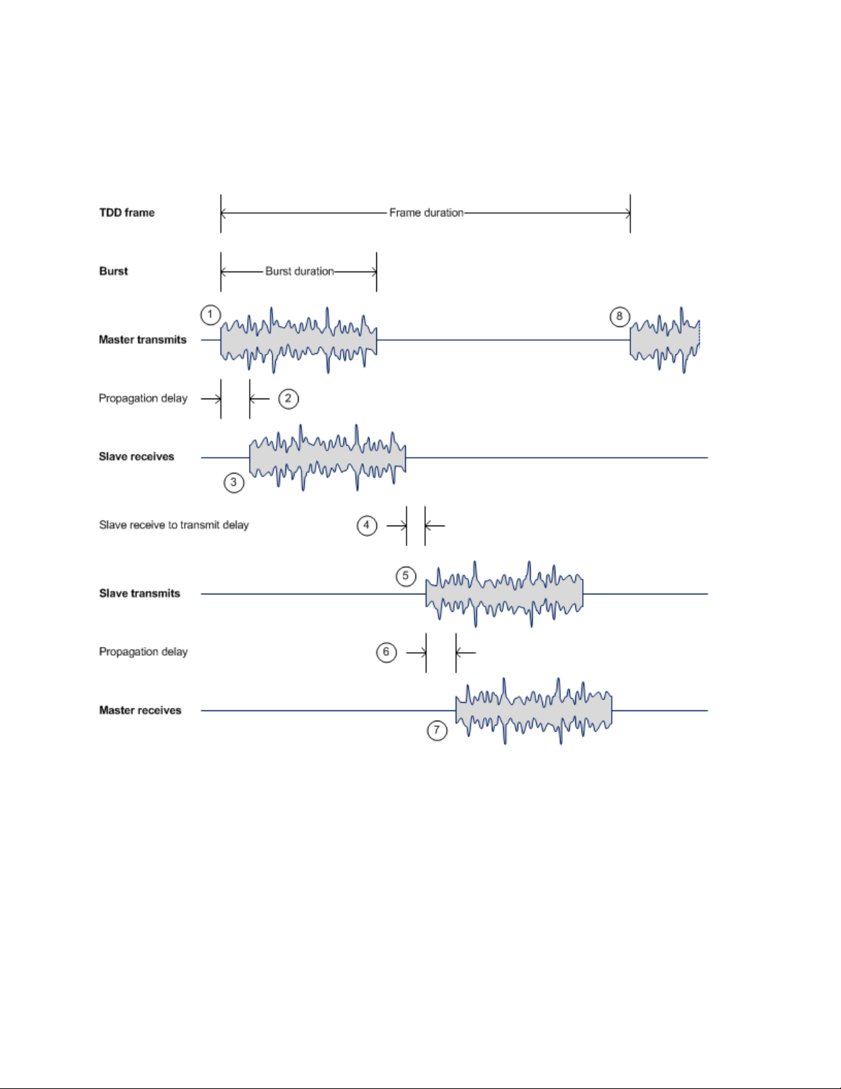
Chapter 1: Product description Wireless operation
Figure 2
The propagation delay in Step 2 is necessarily equal to the propagation delay in Step 6, and is
determined solely by the link range. There may be added delays between rx and tx on the master
and slave to minimize interference, as set up by the link planner or installer.
TDD cycle
Channel selection
The PTP 700 series links are capable of transmitting and receiving on the same channel or on
different channels. In other words, the slave-master direction may use a different channel from the
master-slave direction. Independent selection of transmit and receive frequencies can be useful in
planned networks or for countering interference.
When links operate in radar avoidance regions, each unit monitors its transmit channel for the
presence of radar signals. Therefore, the transmit and receive channels are always identical.
Page 1-7
Page 31

Chapter 1: Product description Wireless operation
For information about…
Refer to…
For information about…
Refer to…
Further reading
TDD synchronization in PTP networks TDD synchronization on page 1-18
Link mode optimization
Link mode optimization allows the PTP 700 link to be optimized according to the type of traffic that
will be bridged. The link supports two modes, IP Traffic and TDM Traffic.
IP traffic
IP Traffic mode is optimized to provide the maximum possible link capacity. IP Traffic mode is an
appropriate choice where applications in the bridged networks provide some measure of reliable
transmission, and where very low latency is not critical. IP mode supports both fixed and adaptive
link symmetry.
TDM traffic
TDM Traffic mode is optimized to provide the lowest possible latency. TDM Traffic mode
additionally implements a more conservative approach to adaptive modulation, leading to lower
error rates in fading channels at the expense of slightly lower link capacity. TDM Traffic mode is an
appropriate choice for delay intolerant data without reliable transmission (for example voice over
IP data). TDM Traffic mode is selected automatically when TDM interfaces are enabled.
Further reading
Effect of IP and TDM modes on link symmetry Link symmetry on page 1-9
Effect of IP and TDM modes on link data
throughput capacity
Effect of IP and TDM modes on system
threshold, output power and link loss
How to configure link mode optimization Wireless Configuration page on page 6-21
Link mode optimization alarms Alarms on page 7-17
Calculating data rate capacity on page 3-27
Data throughput capacity tables on page 3-71
System threshold, output power and link loss
on page 3-60
Page 1-8
Page 32

Chapter 1: Product description Wireless operation
Symmetric –
5:1 –
3:1 –
2:1 –
1:2 –
1:3 –
1:5 –
Adaptive –
Note
Note
Link symmetry
The PTP 700 series provides eight configuration options for apportioning the available capacity
between the two link directions.
•
allocating an equal Burst Duration for the Master and the Slave.
•
The capacity in the direction Master to Slave is five times that of the direction Slave to
Master. The PTP 700 series achieves this by setting the Burst Duration of the Master to five
times that of the Slave
•
The capacity in the direction Master to Slave is three times that of the direction Slave to
Master. The PTP 700 series achieves this by setting the Burst Duration of the Master to three
times that of the Slave.
•
The capacity in the direction Master to Slave is twice that of the direction Slave to Master.
The PTP 700 series achieves this by setting the Burst Duration of the Master to twice that of the
Slave.
•
The capacity in the direction Slave to Master is twice that of the direction Master to Slave.
The PTP 700 series achieves this by setting the Burst Duration of the Slave to twice that of the
Master.
The Master and Slave have equal capacity. The PTP 700 series achieves this by
•
The capacity in the direction Slave to Master is three times that of the direction Master to
Slave. The PTP 700 series achieves this by setting the Burst Duration of the Slave to three
times that of the Master.
•
The capacity in the direction Slave to Master is five times that of the direction Master to
Slave. The PTP 700 series achieves this by setting the Burst Duration of the Slave to five times
that of the Master.
•
direction is dependent on the offered level of network traffic in both link directions. If the level
of offered traffic in both directions is equally high or equally low, the PTP 700 will allocate
equal capacity to both directions. If however the offered level of traffic is greater in one
direction, it is allocated a greater proportion of the overall link capacity. The PTP 700 series
achieves this by increasing (or decreasing) the duration of the Transmit Burst in a given link
direction as the offered level of network traffic increases (or decreases) in this same direction.
This is done independently for the two directions.
This is only available on the Full license. The capacity allocated to a given link
The 5:1, 3:1, 2:1, 1:2, 1:3 and 1:5 modes are not available when TDD synchronization is
enabled, or when TDM services are enabled.
Adaptive mode is not available in the following configurations:
• When link mode optimization is set to TDM Traffic (see Link mode optimization on
page 1-8).
• When TDD synchronization is enabled.
Page 1-9
Page 33

Chapter 1: Product description Wireless operation
For information about…
Refer to…
For information about…
Refer to…
• In regions where radar avoidance is operational (see Radar avoidance on page 1-14).
• When the ODU is not on a Full license.
Further reading
Link symmetry in synchronized networks TDD synchronization on page 1-18
Effect of link symmetry on link data throughput
capacity
How to configure link symmetry Wireless Configuration page on page 6-21
Calculating data rate capacity on page 3-27
Data throughput capacity tables on page 3-71
Further reading
Link range capability upgrade Capability upgrades on page 1-52
Effect of link range on data throughput
capacity
How to generate a license key for maximum
link range
How to configure link ranging Wireless Configuration page on page 6-21
Automatic detection of link range ODU installation tones on page 6-111
Calculating data rate capacity on page 3-27
Data throughput capacity tables on page 3-71
Generating license keys on page 6-3
OFDM and channel bandwidth
The PTP 700 series transmits using Orthogonal Frequency Division Multiplexing (OFDM). This
wideband signal consists of many equally spaced sub-carriers. Although each sub carrier is
modulated at a low rate using conventional modulation schemes, the resultant data rate from the
sub-carriers is high. OFDM works exceptionally over a Non-Line-of-Sight (NLoS) channel.
The channel bandwidth of the OFDM signal is configurable to one of the following values: 5, 10,
15, 20, 30, 40 and 45 MHz. Higher bandwidths provide greater link capacity at the expense of using
more bandwidth. Systems configured for a narrower channel bandwidth provide better receiver
sensitivity and can also be an appropriate choice in deployments where the amount of free
spectrum is limited.
Each channel is offset in center frequency from its neighboring channel by 10 or 5 MHz.
Page 1-10
Page 34

Chapter 1: Product description Wireless operation
Note
For information about…
Refer to…
The Channel Bandwidth must be configured to the same value at both ends of the link.
Not all channel bandwidths are available in all regulatory bands.
Further reading
Channel bandwidths per frequency band General wireless specifications on page 3-21
How to plan for channel bandwidth Channel bandwidth on page 3-23
Effect of channel bandwidth on link data
throughput capacity
How to configure channel bandwidth Wireless Configuration page on page 6-21
How to monitor channel bandwidth Spectrum Management on page 7-26
Calculating data rate capacity on page 3-27
Data throughput capacity tables on page 3-71
Spectrum management
The spectrum management feature of the PTP 700 Series monitors the available wireless spectrum
and directs both ends of the wireless link to operate on a channel with a minimum level of cochannel and adjacent channel interference.
Spectrum management measurements
The PTP 700 Series performs two mean signal measurements per TDD cycle, per channel. This
mean measurement represents the mean received signal power for the 40 microsecond
measurement period.
The Spectrum Management algorithm collects measurements equally from all channels in the
operating band. This process is called the Channel Availability Check (CAC). The CAC uses a
round-robin channel selection process to collect an equal amount of measurements from each
channel. The CAC measurement process is not altered by the channel barring process.
Measurements are still collected for all channels irrespective of the number of barred channels.
Measurement analysis
Spectrum Management uses statistical analysis to process the received peak and mean
measurement. The statistical analysis is based on a fixed, one minute, measurement quantization
period. Spectrum Management collects data for the specified quantization period and only at the
end of the period is the statistical analysis performed.
Page 1-11
Page 35

Chapter 1: Product description Wireless operation
For information about…
Refer to…
Note
Statistical summary
The display of statistical measurement on the Spectrum Expert page always shows a statistical
summary of all channel measurement. The mean and percentile values displayed for each channel
are calculated over a 20 minute statistics window period. All channel decisions are made using the
values computed over the statistics window period.
Spectrum management in fixed frequency mode
The transmit and receive frequencies can be fixed in a PTP 700 wireless link. Once fixed frequency
mode is configured, the spectrum management software will not attempt to move the wireless link
to a channel with lower co-channel and adjacent-channel interference. Therefore this mode of
operation is only recommended for deployments where the installer has a good understanding of
the prevailing interference environment. Care must also be taken to ensure that the frequency
allocations at each end of the link are compatible.
Fixed frequency mode is not available in regions where radar detection is required by the
regulations.
Further reading
How to perform spectrum management Spectrum Management on page 7-26
Adaptive modulation
The PTP 700 series can transport data over the wireless link using a number of different
modulation modes ranging from 256QAM 0.81 to BPSK 0.63. For a given channel bandwidth and
TDD frame structure, each modulation mode transports data at a fixed rate. Also, the receiver
requires a minimum signal to noise ratio in order to successfully demodulate a given modulation
mode. Although the more complex modulations such as 256QAM 0.81 will transport data at a
much higher rate than the less complex modulation modes, the receiver requires a much higher
signal to noise ratio.
The PTP 700 series provides an adaptive modulation scheme where the receiver constantly
monitors the quality of the received signal and notifies the far end of the link of the optimum
modulation mode with which to transmit. In this way, optimum capacity is achieved at all times.
This is one of a number of features which allows the PTP 700 to operate in challenging non-line of
sight radio channels.
LINKPlanner includes an estimate of mean data rate, the data rate provided by each
modulation and the percentage of time spent in each modulation mode.
Page 1-12
Page 36

Chapter 1: Product description Wireless operation
For information about…
Refer to…
Dual Payload
Single Payload
Further reading
Lowest data modulation mode Lowest Data Modulation Mode on page 1-25
Lowest TDM modulation mode Lowest TDM modulation mode on page 1-35
Planning for adaptive modulation Adaptive modulation on page 3-26
Effect of modulation mode on link data
throughput capacity
Effect of modulation mode on system
threshold, output power and link loss
How to configure modulation modes Interface Configuration page on page 6-14
Modulation mode when the ODU is armed Checking that the units are armed on page 6-108
How to view the transmit and receive
modulation modes
Calculating data rate capacity on page 3-27
Data throughput capacity tables on page 3-71
System threshold, output power and link loss on
page 3-60
Wireless Configuration page on page 6-21
System Configuration page on page 6-30
System Status page on page 7-3
System counters on page 7-49
MIMO
Multiple-Input Multiple-Output (MIMO) techniques provide protection against fading and increase
the probability that the receiver will decode a usable signal. When the effects of MIMO are
combined with those of OFDM techniques and a high link budget, there is a high probability of a
robust connection over a non-line-of-sight path.
The PTP 700 transmits two signals on the same radio frequency, one of which is vertically
polarized and the other horizontally polarized. Depending on the channel conditions, the PTP 700
will adapt between two modes of operation:
•
and parallel data streams, one on the vertical channel and one on the horizontal channel. This
doubles the capacity of the PTP 700.
•
detect this and switch to a mode which transmits the same data stream on both vertical and
horizontal channels. This provides polar diversity and is another key feature which allows the
PTP 700 to operate in challenging non- line of sight radio channels.
Lower order modulations (BPSK 0.63 up to QPSK 0.87) only operate in single payload mode.
Higher order modulations (16QAM 0.63 to 256QAM 0.81) are available in single payload mode and
dual payload mode. The switching between modes is automatically controlled by the adaptive
modulation feature described in Adaptive modulation on page 1-12.
: When the radio channel conditions allow, the PTP 700 will transmit two different
: As the radio channel becomes more challenging, the PTP 700 has the ability to
Page 1-13
Page 37

Chapter 1: Product description Wireless operation
Note
For information about…
Refer to…
For information about…
Refer to…
The system automatically chooses between dual and single payload to try to increase
the capacity of a link. However the user can disable the dual payload mode, forcing
the more robust option of single payload.
Further reading
How to configure dual or single payload Wireless Configuration page on page 6-21
Single and dual payload modulation modes System threshold, output power and link loss
on page 3-60
TDM single payload lock feature TDM on page 7-13
Dynamic spectrum optimization
The PTP 700 series uses an interference mitigation technique known as Dynamic Spectrum
Optimization (DSO). Both the Master and Slave continually monitor for interference on all channels
and then select the best frequency of operation. This is a dynamic process where the PTP 700 can
continually move channels in response to changes in interference. Two modes of operation are
available:
• First mode: the two link directions are forced to select the same frequency, determined by the
Master.
• Second mode: the frequency of operation can be determined independently for each direction.
This mode is not permitted in radar regions.
Further reading
Using DSO in PTP networks Using Dynamic Spectrum Optimization on page 1-17
Planning to use DSO Frequency selection on page 3-23
How to configure DSO Wireless Configuration page on page 6-21
Asymmetric DSO in non-radar regions Spectrum Management Settings on page 7-31
Radar avoidance
In regions where protection of radars is part of the local regulations, the PTP 700 must detect
interference from radar-like systems and avoid co-channel operation with these systems.
Page 1-14
Page 38

Chapter 1: Product description Wireless operation
For information about…
Refer to…
To meet this requirement, the PTP 700 implements the following features:
• The radar detection algorithm will always scan a usable channel for 60 seconds for radar
interference before making the channel an available channel.
• This compulsory channel scan will mean that there is at least 60 seconds service outage every
time radar is detected and that the installation time is extended by at least 60 seconds even if
no radar is found.
• When operating on a channel, the spectrum management algorithm implements a radar
detection function which looks for impulsive interference on the operating channel. If
impulsive interference is detected, spectrum management will mark the current operating
channel as having detected radar (unavailable channel) and initiate a channel hop to an
available channel. The previous operating channel will remain in the unavailable state for
thirty minutes after the impulsive interference pulse was detected.
• After the thirty minutes have expired the channel will be returned to the usable channel pool.
There is a secondary requirement for bands requiring radar avoidance. Regulators have mandated
that products provide a uniform loading of the spectrum across all devices. In general, this
prevents operation with fixed frequency allocations. However:
• ETSI regulations do allow frequency planning of networks (as that has the same effect of
spreading the load across the spectrum).
• The FCC does allow channels to be barred if there is actually interference on them.
Fixed frequency allocation is not recommended in radar avoidance regions, as any radar detection
would cause a system outage of at least 30 minutes.
Further reading
Radar avoidance in the country of operation License keys and regulatory bands on page 1-16
Planning for mandatory radar detection Frequency selection on page 3-23
Radar avoidance when aligning antennas ODU installation tones on page 6-111
Effect of radar detection on spectrum
management
Spectrum Expert page in radar avoidance mode
on page 7-37
Encryption
The PTP 700 supports optional encryption for data transmitted over the wireless link. The
encryption algorithm used is the Advanced Encryption Standard (AES) with 128-bit and 256-bit key
size. AES is a symmetric encryption algorithm approved by U.S. Government organizations (and
others) to protect sensitive information. The AES implementation in PTP 700 is approved to FIPS-
197. Encryption is enabled through the purchase of an upgrade.
Page 1-15
Page 39

Chapter 1: Product description Wireless operation
For information about…
Refer to…
Caution
Attention
Further reading
AES requirement for HTTPS/TLS Transport layer security on page 1-42
AES requirement for SNMPv3 security User-based security model on page 1-46
Licensing AES encryption AES license on page 1-49
Capability upgrades on page 1-52
Planning to use AES for HTTPS/TLS Planning for HTTPS/TLS operation on page 3-51
How to generate AES license keys Generating license keys on page 6-3
How to configure AES encryption System Configuration page on page 6-30
How to configure AES encryption for
HTTPS/TLS operation
Security menu on page 6-93
License keys and regulatory bands
The PTP 700 license key specifies the country of operation for the ODU, and lists the regulatory
bands that are licensed by regulators in that country. If a license key provides access to more than
one regulatory band, PTP 700 provides a choice between the available bands. In each regulatory
band, PTP 700 sets the following aspects of wireless operation to comply with the applicable
regulations:
• Maximum transmit power
• Radar avoidance
• Transmit power reduction in edge channels
• Frequency range
• Channel plan
The country of operation (and thus the supported regulatory bands) can be changed by generating
a new license key at the License Key Generator page of the Cambium web-site, and entering the
new license key using the Installation Wizard.
To avoid possible enforcement action by the country regulator, always operate links in
accordance with local regulations.
Pour éviter une éventuelle sanction par le régulateur du pays, utiliser toujours nos
liaisons radiofréquences conformément à la réglementation locale.
Page 1-16
Page 40

Chapter 1: Product description Wireless operation
For information about…
Refer to…
Further reading
Planning PTP 700 links to conform to the
regulatory band restrictions
Radio regulations in the country of operation Compliance with radio regulations on page
How to generate a license key for the country of
operation
How to configure the regulatory band Wireless Configuration page on page 6-21
How to view the regulatory band System Status page on page 7-3
Regulatory band alarms Alarms on page 7-17
Radio spectrum planning on page 3-21
4-28
Generating license keys on page 6-3
PTP networks
Using Dynamic Spectrum Optimization
The Dynamic Spectrum Optimization (DSO) feature allows a PTP 700 unit to select wireless
channels for a lower level of radio frequency (RF) interference. This approach is appropriate where
the network consists of a small number of PTP links, or where the RF interference is predominantly
from equipment belonging to other operators.
Using frequency planning
Networks will benefit from the use of fixed channel allocations if (a) the network consists of
multiple PTP links, and (b) RF interference predominantly arises from equipment in the same
network.
Frequency planning is the exercise of assigning operating channels to PTP units so as to minimize
RF interference between links. Frequency planning must consider interference from any PTP unit
to any other PTP unit in the network. Low levels of interference normally allow for stable operation
and high link capacity.
The frequency planning task is made more straightforward by use of the following techniques:
• Using several different channels
• Separating units located on the same mast
• Using high performance (directional) external antennas
Synchronized networks
TDD synchronization can be used to relax constraints on the frequency planning of PTP networks.
Synchronization has the following benefits:
Page 1-17
Page 41

Chapter 1: Product description Wireless operation
For information about…
Refer to…
Caution
• Allows tighter frequency re-use, and thus wider channel bandwidth.
• Allows more convenient collocation of units on a single mast.
• Allows use of smaller or lower performance antennas.
• Reduces inference, resulting in use of more efficient modulation modes.
In a correctly designed synchronised network, all links are configured with the same TDD frame
duration, and the TDD frame contains guard periods longer than the propagation delay between
the most distant interfering units.
Each synchronized unit is assigned to one of two phases. A master ODU can be assigned to either
phase. A slave ODU must be assigned to a different phase from the associated master ODU. The
phase is set by suitable configuration of TDD Frame Offset.
TDD synchronization eliminates RF interference between units in the same phase. This means that
frequency planning in a synchronized network is concerned only with interference between units
in different phases. Frequency planning is still necessary, but the number of potential interference
paths to be considered is halved. Frequency planning in a synchronized TDD network has
approximately the same level of complexity as frequency planning in a Frequency Division Duplex
(FDD) network.
Further reading
How to plan networks Chapter 3: System planning, or contact your
Cambium distributor or re-seller.
TDD synchronization (PTP-SYNC)
Additional hardware is needed to synchronize PTP 700 links. One PTP-SYNC unit is required for
each master ODU. The PTP-SYNC unit is connected in line in the drop cable between the PSU and
the ODU, and is collocated with the PSU.
The PTP-SYNC is compatible only with the PTP 650/700 AC + DC Power Injector.
The PTP 650 AC Power Injector will not work with a PTP-SYNC, and it is likely that a
fuse will be blown in the PTP-SYNC if this is attempted.
Timing references for use with PTP-SYNC
PTP-SYNC requires an external timing reference in all but the simplest networks. Up to ten
PTP-SYNCs can be connected in a chain to share the timing signal from one timing reference. In
the majority of applications, one reference is required for each site that contains PTP 700 master
ODUs.
Page 1-18
Page 42

Chapter 1: Product description Wireless operation
For information about…
Refer to…
The timing reference can be from any timing system that provides a 1 Hz signal, accurately
synchronized in frequency and phase with a network-wide master timing reference. GPS timing
receivers are a very practical way of obtaining a suitable reference. The PTP-SYNC is compatible
with the Trimble Acutime™ GG and Trimble Acutime™ Gold GPS receivers.
In simple networks where all master ODUs are at a single site, the external reference can be
omitted. In this case, one ODU acts as a reference for other collocated units.
Configuring the TDD frame
In synchronized operation, frame duration and burst duration must be configured directly in the
web-based management interface. Frame duration must be identical across all links in a
synchronized network.
The PTP Link Planner provides a capability for computing suitable frame parameters in a
synchronized network. Please refer to the Link Planner User Guide for guidance on configuring
TDD synchronization.
Link symmetry is always 1:1 in synchronized networks.
Link capacity in synchronized networks
The TDD frame duration is extended in synchronized networks to allow for the propagation delay
of the longest link in the network and to incorporate additional guard periods. These guard periods
protect against delayed interference from distant units in the same network.
The longer frame duration results in slightly lower link capacity than for an equivalent nonsynchronized link with the same channel bandwidth and modulation mode. However, TDD
synchronization also reduces interference, and this may allow operation in higher modulation
modes. The benefit of operating in a higher modulation mode normally outweighs the penalty of
the slightly longer TDD frame.
Further reading
The PTP-SYNC unit PTP-SYNC unit on page 2-44
The GPS receiver GPS receiver on page 2-50
Typical deployment diagrams for GPS GPS receiver interfaces on page 3-9
Choosing a site for the PTP-SYNC unit PTP-SYNC location on page 3-16
Choosing a site for the GPS receiver GPS receiver location on page 3-16
Use of LINKPlanner for TDD
synchronization
TDD synchronization methods that may be
implemented using PTP-SYNC
How to install a PTP-SYNC unit Installing a PTP-SYNC unit on page 5-26
LINKPlanner for synchronized networks on page
3-26
Configuration options for TDD synchronization
on page 3-31
Page 1-19
Page 43

Chapter 1: Product description Wireless operation
For information about…
Refer to…
How to install an optional GPS receiver Installing a GPS receiver on page 5-30
How to enable TDD synchronization Wireless Configuration page on page 6-21
How to configure TDD synchronization TDD synchronization page (optional) on page 6-
27
How to view TDD synchronization status System Status page on page 7-3
TDD synchronization alarms Alarms on page 7-17
How to test a PTP-SYNC installation when a
fault is suspected
Testing PTP-SYNC on page 8-15
Page 1-20
Page 44

Chapter 1: Product description Ethernet bridging
Main PSU
Aux:
SFP:
Note
Ethernet bridging
This section describes how the PTP 700 processes Ethernet data, and how Ethernet ports are
allocated to the Data Service, Second Data Service, Management Service and Local Management
Service.
Ethernet ports
The PTP 700 Series ODU has three Ethernet ports:
•
1000BASE-T, and accepts power from the AC+DC Enhanced Power Injector to the ODU using a
proprietary power over Ethernet (PoE) method.
•
supplies power from the ODU to external equipment using standards-based power over
Ethernet (PoE) complying with IEEE 802.3at.
•
modules supplied as part of the SFP module kit.
: The Main PSU port provides a copper Ethernet interface for 100BASE-TX and
The Aux port provides a copper Ethernet interface for 100BASE-TX and 1000BASE-T, and
The SFP port is a small format pluggable receptacle accepting copper or optical plug-in
The PTP 700 provides flexible interconnection of customer data and network
management using several Ethernet ports, but it does not contain a general-purpose
Ethernet switch, and it is not possible to forward traffic between the Ethernet ports of
the same ODU.
Data and management services
The PTP 700 Series ODU supports four different types of virtual circuits providing data and
management services.
Data Service
This point-to-point transparent service carries customer’s data between one of the Ethernet ports
at the local ODU and one of the Ethernet ports at an associated remote ODU. Every link is
configured with exactly one instance of the Data Service.
The Data Service provides comprehensive Quality of Service classification with up to eight queues.
Page 1-21
Page 45

Chapter 1: Product description Ethernet bridging
Note
Note
Second Data Service
This optional point-to-point transparent service offers a second virtual circuit for customer’s data
between one of the Ethernet ports at the local ODU and one of the Ethernet ports at an associated
remote ODU. The Data Service and Second Data Service are always mapped to different ports at
an ODU. The Data traffic of the two services are distinct and are separately bridged to the
appropriate configured remote ODU port.
The Second Data Service is available only with a Full capacity license.
The Second Data Service provides a single class of service, which can be configured to match any
of the eight classes of the Data Service.
Management Service
PTP 700 provides options for In-Band and Out-of-Band network management.
The In-Band Management Service connects management systems at both ends of the link with the
embedded management agents in the ODUs, accessed using the Ethernet ports selected to the
Data Service or the Second Data Service.
The Out-of-Band Management Service connects management systems at both ends of the link
with the embedded management agents in the ODUs, accessed using dedicated Ethernet ports.
Out-of-Band Management is not available when the optional Second Data Service is
enabled.
The Out-of-Band Management Service provides a single class of service, which can be configured
to match any of the eight classes of the Data Service.
The PTP 700 provides flexible interconnection of customer data and network
management using several Ethernet ports, but it does not contain a general-purpose
Ethernet switch, and it is not possible to forward traffic between the Ethernet ports of
the same ODU.
Local Management Service
PTP 700 provides option for local network management.
The Local Management network is isolated from the customer data network. Management frames
are not forwarded over the wireless link. The management agents can access only through the
OOB Local ports at the respective ODUs.
Page 1-22
Page 46

Chapter 1: Product description Ethernet bridging
For information about…
Refer to…
Further reading
A more detailed description of the Data
Service
A more detailed description of the
Second Data Service
A more detailed description of the Outof-Band Management Service
SFP optical or copper module kits SFP module kits on page 2-41
The PSU, AUX and SFP ports of the ODU ODU interfaces on page 2-12
Diagrams showing Ethernet connections Typical deployment on page 3-2
How to plan the use of Ethernet ports for
customer and management traffic
How to install the Ethernet interfaces to
the ODU
How to configure the ODU Ethernet
ports
Data Service on page 1-21
Second Data Service on page 1-22
Management Service on page 1-22
Ethernet interfaces on page 3-35
Installing the copper Cat5e Ethernet interface on
page 5-16
Installing an SFP Ethernet interface on page 5-26
Installing an Aux Ethernet interface on page 5-55
Interface Configuration page on page 6-14
LAN Configuration page on page 6-34
Ethernet port status attributes Ethernet / Internet on page 7-6
Ethernet port alarms Alarms on page 7-17
Data network
Transparent Ethernet service
The PTP 700 Series provides an Ethernet service between one of the Ethernet ports at a local ODU
and one of the Ethernet ports at an associated remote ODU. The Ethernet service is based on
conventional layer two transparent bridging, and is equivalent to the Ethernet Private Line (EPL)
service defined by the Metro Ethernet Forum (MEF).
The service is transparent to untagged frames, standard VLAN frames, priority-tagged frames,
provider bridged frames, Q-in-Q frames and provider backbone bridged frames. In each case, the
service preserves MAC addresses, VLAN ID, Ethernet priority and Ethernet payload in the
forwarded frame. The maximum frame size for bridged frames in the customer network is
9600 bytes.
Page 1-23
Page 47

Chapter 1: Product description Ethernet bridging
Data Service
There is no requirement for the customer data network to be connected to the same Ethernet port
at both ends of a wireless link. For example, it is possible to connect the Main PSU port to the
customer data network at one end of the link and to connect the Aux port to the customer data
network at the other end of the link.
Layer two control protocols
The Data Service in the PTP 700 Series is transparent to layer two control protocols (L2CP)
including:
• Spanning tree protocol (STP), rapid spanning tree protocol (RSTP)
• Multiple spanning tree protocol (MSTP)
• Link aggregation control protocol (LACP)
• Link OAM, IEEE 802.3ah
• Port authentication, IEEE 802.1X
• Ethernet local management interface (E-LMI), ITU-T Q.933.
• Link layer discovery protocol (LLDP)
• Multiple registration protocol (MRP)
• Generic attribute registration protocol (GARP)
The PTP 700 Series does not generate or respond to any L2CP traffic.
Quality of service for bridged Ethernet traffic
The PTP 700 Series supports eight traffic queues in the
for transmission over the wireless link. Ethernet frames are classified by inspection of
priority code point in the outermost VLAN tag, the Differentiated Services Code Point (DSCP) in an
IPv4 or IPv6 header including DSCP in an IPv4 or IPv6 datagrams encapsulated in PPP and PPPoE
headers,
or the Traffic Class in an MPLS header.
for Ethernet frames waiting
the Ethernet
PTP 700 provides a configurable mapping between Ethernet, IP or MPLS priority and transmission
queue, together with a simple way to restore a default mapping based on the recommended
default in IEEE 802.1Q-2005. Untagged frames, or frames with an unknown network layer protocol,
can be separately classified.
Scheduling for transmission over the wireless link is by strict priority. In other words, a frame at
the head of a given queue is transmitted only when all higher priority queues are empty.
Fragmentation
The PTP 700 Series minimizes latency and jitter for high-priority Ethernet traffic by fragmenting
Ethernet frames before transmission over the wireless link. The fragment size is selected
automatically according to channel bandwidth and modulation mode of the wireless link.
Fragments are reassembled on reception, and incomplete Ethernet frames are discarded.
Page 1-24
Page 48

Chapter 1: Product description Ethernet bridging
For information about…
Refer to…
Data port wireless link down alert
The PTP 700 Series provides an optional indication of failure of the wireless link by means of a
brief disconnection of the copper or optical data port allocated to the customer data network. The
Wireless link down alert can be used to trigger protection switching by Spanning Tree Protocol
(STP) or Ethernet Automatic Protection Switching (EAPS) and other higher layer protocols in a
redundant network.
Lowest Data Modulation Mode
The PTP 700 ODU can be configured to discard Ethernet frames in the Data Service when the
modulation mode is lower than the configured Lowest Data Modulation Mode.
This feature is likely to be useful in networks that have alternate routes, for example in a ring or
mesh topology where EAPS or RSTP is used to resolve loops. In this application, Lowest Data
Modulation Mode should be set to ensure that an active link will provide at least the minimum
necessary capacity for high-priority constant bit rate traffic such as voice over IP or TDM pseudo
wire. An active link will be blocked when the capacity falls below the minimum required, triggering
a routing change in associated Ethernet switches to bring alternate links into use.
Lowest Data Modulation Mode should normally be set to BPSK 0.63 Single in simply connected
tree networks or other topologies that do not have alternative routes.
Further reading
Factors to be considered when planning
PTP 700 customer data networks
How to configure the Ethernet service LAN Configuration page on page 6-34
How to configure Ethernet quality of service QoS Configuration page on page 6-44
How to monitor Ethernet performance System statistics on page 7-47
Data network planning on page 3-35
Second Data network
Transparent Ethernet service
The PTP 700 Series provides an optional second Ethernet data service between one of the Ethernet
ports at a local ODU and one of the Ethernet ports at an associated remote ODU. The Ethernet
service is based on conventional layer two transparent bridging. The PTP 700 maintains complete
separation between Ethernet traffic in the data service and the second data service.
Page 1-25
Page 49

Chapter 1: Product description Ethernet bridging
The service is transparent to untagged frames, standard VLAN frames, priority-tagged frames,
provider bridged frames, Q-in-Q frames and provider backbone bridged frames. In each case, the
service preserves MAC addresses, VLAN ID, Ethernet priority and Ethernet payload in the
forwarded frame. The maximum frame size for bridged frames in the second data service is 2000
bytes.
There is no requirement for the second data service to be connected to the same Ethernet port at
both ends of a wireless link. For example, it is possible to connect the Main PSU port to the second
data service at one end of the link and to connect the Aux port to the second data service at the
other end of the link.
Layer two control protocols
The Second Data Service in the PTP 700 Series is transparent to layer two control protocols (L2CP)
including:
• Spanning tree protocol (STP), rapid spanning tree protocol (RSTP)
• Multiple spanning tree protocol (MSTP)
• Link aggregation control protocol (LACP)
• Link OAM, IEEE 802.3ah
• Port authentication, IEEE 802.1X
• Ethernet local management interface (E-LMI), ITU-T Q.933.
• Link layer discovery protocol (LLDP)
• Multiple registration protocol (MRP)
• Generic attribute registration protocol (GARP)
The management service in the PTP 700 Series does not generate or respond to any L2CP traffic.
Quality of service for bridged Ethernet traffic
The PTP 700 Series supports a single traffic queue in the Second Data Service for Ethernet frames
waiting for transmission over the wireless link. The priority of the queue can be varied with respect
to the eight queues used for the data service.
Fragmentation
Ethernet frames in the PTP 700 Series Second Data Service are always fragmented for
transmission over the wireless link, even when the single queue for the Second Data Service has
higher priority than all of the data service queues.
Second Data port wireless link down alert
The PTP 700 Series provides an optional indication of failure of the wireless link by means of a
brief disconnection of the copper or optical data port allocated to the Second Data Service. The
Wireless link down alert can be used to trigger protection switching by Spanning Tree Protocol
(STP) or Ethernet Automatic Protection Switching (EAPS) and other higher layer protocols in a
redundant network.
Page 1-26
Page 50

Chapter 1: Product description Ethernet bridging
For information about…
Refer to…
Lowest Second Data Modulation Mode
The PTP 700 ODU can be configured to discard Ethernet frames in the Second Data Service when
the modulation mode is lower than the configured Lowest Second Data Modulation Mode.
This feature is likely to be useful in networks that have alternate routes, for example in a ring or
mesh topology where EAPS or RSTP is used to resolve loops. In this application, Lowest Second
Data Modulation Mode should be set to ensure that an active link will provide at least the
minimum necessary capacity for high-priority constant bit rate traffic such as voice over IP or TDM
pseudo wire. An active link will be blocked when the capacity falls below the minimum required,
triggering a routing change in associated Ethernet switches to bring alternate links into use.
Lowest Second Data Modulation Mode should normally be set to BPSK 0.63 Single in simply
connected tree networks or other topologies that do not have alternative routes.
Further reading
Factors to be considered when planning
PTP 700 customer data networks
How to configure the Ethernet Second Data
Service
How to configure Ethernet quality of service QoS Configuration page on page 6-44
How to monitor Ethernet performance System statistics on page 7-47
Out-of-Band Management Service
Data network planning on page 3-35
LAN Configuration page on page 6-34
Transparent Ethernet service
The PTP 700 Series provides an optional Ethernet service for out-of-band network management
between one of the Ethernet ports at a local ODU and one of the Ethernet ports at an associated
remote ODU. The Ethernet service is based on conventional layer two transparent bridging. The
PTP 700 maintains complete separation between Ethernet traffic in the customer Data Service and
the Management Service.
The service is transparent to untagged frames, standard VLAN frames, priority-tagged frames,
provider bridged frames, Q-in-Q frames and provider backbone bridged frames. In each case, the
service preserves MAC addresses, VLAN ID, Ethernet priority and Ethernet payload in the
forwarded frame. The maximum frame size for bridged frames in the management network is 2000
bytes.
There is no requirement for the management network to be connected to the same Ethernet port at
both ends of a wireless link. For example, it is possible to connect the Main PSU port to the
management network at one end of the link and to connect the Aux port to the management
network at the other end of the link.
Page 1-27
Page 51

Chapter 1: Product description Ethernet bridging
Layer two control protocols
The Management Service in the PTP 700 Series is transparent to layer two control protocols (L2CP)
including:
• Spanning tree protocol (STP), rapid spanning tree protocol (RSTP)
• Multiple spanning tree protocol (MSTP)
• Link aggregation control protocol (LACP)
• Link OAM, IEEE 802.3ah
• Port authentication, IEEE 802.1X
• Ethernet local management interface (E-LMI), ITU-T Q.933.
• Link layer discovery protocol (LLDP)
• Multiple registration protocol (MRP)
• Generic attribute registration protocol (GARP)
The management service in the PTP 700 Series does not generate or respond to any L2CP traffic.
Quality of service for bridged Ethernet traffic
The PTP 700 Series supports a single traffic queue in the Management Service for Ethernet frames
waiting for transmission over the wireless link. The priority of the queue can be varied with respect
to the eight queues used for the Data Service.
Fragmentation
Ethernet frames in the PTP 700 Series management service are always fragmented for
transmission over the wireless link, even when the single queue for the management service has
higher priority than all of the customer data queues.
Management port wireless Down Alert
The PTP 700 Series provides an optional indication of failure of the wireless link by means of a
brief disconnection of the copper or optical data port allocated to the management network. The
Wireless link down alert can be used to trigger protection switching by Spanning Tree Protocol
(STP) or Ethernet Automatic Protection Switching (EAPS) and other higher layer protocols in a
redundant network.
Lowest Data Modulation Mode
The Lowest Data Modulation Mode attribute does not prevent bridging in the management
service. See Lowest Data Modulation Mode on page 1-25.
Page 1-28
Page 52

Chapter 1: Product description Ethernet bridging
For information about…
Refer to…
For information about…
Refer to…
Further reading
Factors to be considered when planning
PTP 700 management data networks
How to configure the Ethernet service LAN Configuration page on page 6-34
How to configure Ethernet quality of service QoS Configuration page on page 6-44
How to monitor Ethernet performance System statistics on page 7-47
Ethernet loopback mode
PTP 700 provides a local Ethernet loopback function that can be used to loop traffic between the
Aux Port and one of the other Ethernet ports.
Loopback is intended to assist in the commissioning of a camera or other auxiliary device
collocated with the PTP 700 ODU. For example, when setting up a camera which will ultimately be
connected to the wireless bridge, it may be useful to loop the data back to a second local interface,
to assist in the positioning and alignment of the camera.
When ports are configured for Ethernet local loopback, they are temporarily disconnected from
their allocated function and connected together internally within the PTP 700 ODU. The
Management Service and Local Management Service are disconnected from a port configured for
loopback. In this case, it will not be possible to manage the ODU from a local Ethernet port. For
this reason the Ethernet loopback is always disabled when the ODU is rebooted or power-cycled,
restoring the previous port configuration and any associated management paths.
Data network planning on page 3-35
During loopback operation, the same frame size restrictions that apply to management traffic are
present, jumbo frames are not supported and the maximum frame size is restricted to 1536 bytes.
Loopback is able to loop between Ethernet ports operating at different line rates if required, and it
is possible to configure a Loopback between ports operating at 1000BASE-T/LX/SX and
100BASE-TX if needed.
Further reading
How to configure Ethernet loopback LAN Configuration page on page 6-34
Page 1-29
Page 53
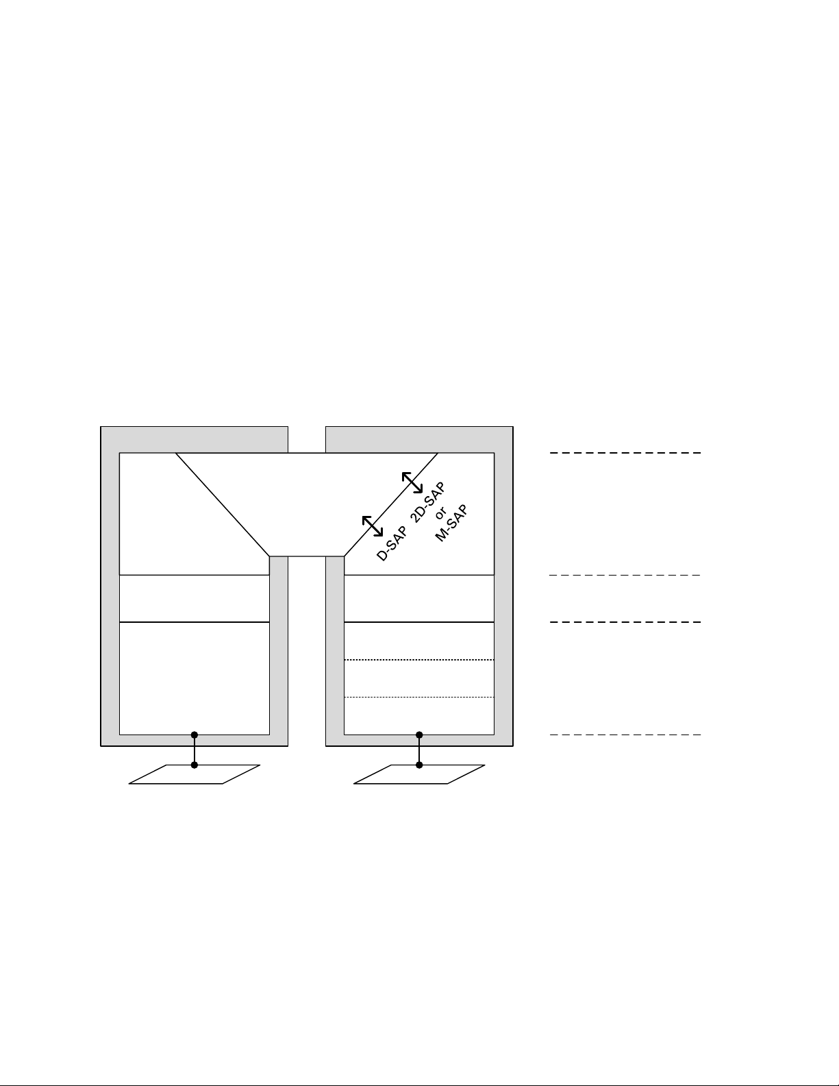
Chapter 1: Product description Ethernet bridging
Figure 3
Wireless PortEthernet Port
IEEE 802.3
Media Access Method
Independent
Functions
Media Access Method Dependent
Convergence Functions
Media Access Method
Specific Functions
Ethernet Wireless
PTP Medium Access
Method
PTP Security
(Optional)
PTP Physical Layer
MAC Relay E ntity
D-SAP = Data Service Access Point
2D-SAP = Second Data Service Access Point
M-SAP = Management Service Access Point
Protocol model
Ethernet bridging behavior at each end of the wireless link is equivalent to a two-port, managed,
transparent MAC bridge where the two ports are a wired Ethernet port allocated to the Data
Service, Second Data Service, Out-of-Band Management Service, and the Wireless port.
Frames are transmitted at the Wireless port over a proprietary point-to-point circuit-mode link
layer between ends of the PTP 700 link. The Wireless Port provides two distinct service access
ports (SAPs) where the first is always used for the Data Service, while the second is used by either
the Second Data Service or Out-of-Band Management Service.
Ethernet frames received at the Ethernet ports, or generated internally within the management
agent, are encapsulated within a lightweight MAC layer for transmission over the wireless link.
Protocol layers involved in bridging between Ethernet and wireless interfaces are shown in Figure
3. Protocol layers involved in bridging between external interfaces and the management agent are
shown in Figure 4. In these figures, the layers have the meanings defined in IEEE 802.1Q-2005.
Protocol layers between Ethernet and wireless interfaces
Page 1-30
Page 54
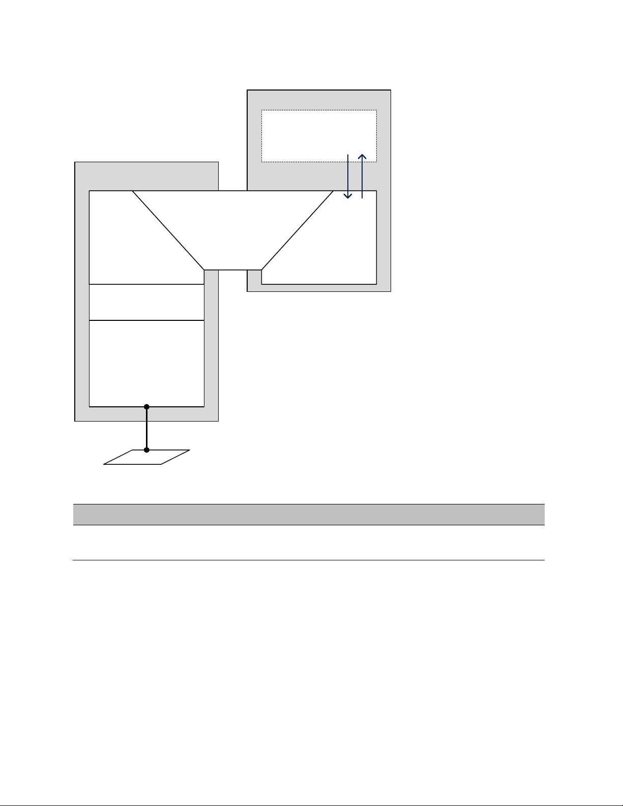
Chapter 1: Product description Ethernet bridging
Figure 4
Management Agent
Management, Wireless,
Data Ports
Media Access Method
Specific Functions
HTTP/SNMP/SMTP
TCP/IP
MAC Relay E ntity
For information about…
Refer to…
Protocol layers between external interfaces and the management agent
Further reading
Layer two control protocols (L2CPs)
identified by PTP 700
Synchronous Ethernet
PTP 700 provides a Synchronous Ethernet function. When enabled, the frequency and phase of the
Ethernet clock is transferred to the other end of the radio link, enabling operation as part of an
ITU-T G.781 Synchronous Digital Hierarchy.
Synchronisation Status Messages (SSM) are processed and transmitted as specified by ITU-T
G.8264 and in Section 5 of G.781.
Layer two control protocols on page 3-35
Page 1-31
Page 55

Chapter 1: Product description Ethernet bridging
For information about…
Refer to…
Note
Further reading
Relationship between synchronous
Ethernet and TDM
Availability of synchronous Ethernet Capability upgrades on page 1-52
Relationship between synchronous
Ethernet and Ethernet port allocation
How to configure synchronous Ethernet LAN Configuration page on page 6-34
Upgrading to synchronous Ethernet Generating license keys on page 6-3
Synchronous Ethernet status indicators Synchronous Ethernet on page 7-10
Synchronous Ethernet alarms Alarms on page 7-17
IEEE 1588-2008 Transparent Clock
PTP 700 is capable of operating as an IEEE 1588-2008 Transparent Clock. When operational, IEEE
1588-2008 event frames (Sync, Delay_Req, Pdelay_Req, Pdelay_Resp) have their “Correction Field”
adjusted to reflect the residence time of the frame in the system. This results in greatly improved
performance of downstream 1588-2008 slave clocks. The Transparent Clock feature is available at
the Main PSU Port and at the SFP Port when a fiber SFP module is installed.
TDM description on page 1-34
Additional port allocation rules on page 3-44
Unicast and multicast addressing models are supported, along with UDP over IPv4 or IPv6, and
Ethernet communication services. The IEEE 1588 messages can be encapsulated in Untagged, Ctagged, S-tagged, S-C-tagged and C-C-tagged Ethernet frames.
For the most accurate residence time corrections, use Synchronous Ethernet in
conjunction with the Transparent Clock feature. In this configuration, PTP 700 uses the
Synchronous Ethernet clock to increase the accuracy of 1588 residence time
measurements.
Page 1-32
Page 56

Chapter 1: Product description Ethernet bridging
For information about…
Refer to…
Further reading
Relationship between IEEE 1588-2008 Transparent
Clock and TDM
Availability of IEEE 1588-2008 Transparent Clock Capability upgrades on page 1-52
Relationship between IEEE 1588-2008 Transparent
Clock and Ethernet port allocation
Relationship between IEEE 1588-2008 Transparent
Clock and VLAN membership
Upgrading to IEEE 1588-2008 Generating license keys on page 6-3
How to configure IEEE 1588-2008 Transparent
Clock
IEEE 1588-2008 Transparent Clock status
indicators
IEEE 1588-2008 Transparent Clock alarms Alarms on page 7-17
TDM description on page 1-34
Additional port allocation rules on page 3-
44
VLAN membership on page 3-45
LAN Configuration page on page 6-34
Synchronous Ethernet on page 7-10
Page 1-33
Page 57

Chapter 1: Product description TDM bridging
TDM bridging
This section describes how TDM traffic (E1 or T1) may be carried over PTP 700 links.
If a NIDU is installed at each link end, the PTP 700 link supports up to eight E1 channels or up to
eight T1 channels. The link relays unstructured E1 or T1 data and provides accurate timing
transfer.
TDM description
PTP 700 Series bridges up to eight E1 or T1 telecoms circuits over a single-hop PTP 700 wireless
link using the optional Network Indoor Unit (NIDU). The NIDU provides the eight TDM interfaces
on individual RJ45/RJ48 connectors, together with an Ethernet interface to the operator’s data
network and a separate Ethernet interface to the PTP 700 Series ODU. One NIDU is required at
each end of the link. It operates from a 48 V DC power supply.
TDM circuits established using the NIDUs are structure agnostic, meaning that the circuits can
bridge framed or unframed data.
The NIDUs are tightly integrated with associated ODUs providing for simple configuration,
accurate timing transfer, low and predictable latency, high efficiency, quick settling time, and a
timing-only mode that maintains timing transfer when the wireless link has insufficient capacity to
bridge the configured TDM data.
Through timing
TDM bridging in the PTP 700 series uses the “through timing” model. In other words, the clock
frequency used for transmitting TDM data is, on average, exactly the same as the clock frequency
received at the corresponding TDM port at the remote end of the link. The wander and jitter in the
transmit clock complies with applicable requirements of ITU-T G.823 and G.824 without additional
external frequency references. Timing transfer is independent between individual circuits, and
between transmit and received directions of the same circuit.
NIDUs and TDM
TDM circuits in PTP 700 span a single wireless link. To transmit TDM data across a network
segment consisting of several wireless links, use one pair of NIDUs for each wireless link, and
interconnect the TDM ports at relay sites.
The NIDU is not a general-purpose TDM multiplexer, and will not interwork with standards-based
products from other manufacturers. The NIDU does not support (and does not need to support)
internal, external or loop timing modes. The NIDU does not accept (or need) an external frequency
reference.
The NIDU is not separately managed, and it does not have an IP address. Instead, the ODU is used
to configure and monitor the associated NIDU through the standard HTTP/HTTPS, SNMP, SMTP
and syslog interfaces already used by the ODU.
Page 1-34
Page 58

Chapter 1: Product description TDM bridging
The NIDU always connects to the ODU using the Main PSU port of the ODU. This constrains the
flexible allocation of ports to services somewhat.
Timing transfer for TDM circuits
Accurate timing transfer for TDM circuits in the PTP 700 Series is based on the same underlying
technology as the IEEE 1588 Transparent Clock and Synchronous Ethernet features. Consequently,
the IEEE 588 and Synchronous Ethernet features are not available when TDM bridging is enabled.
Similarly, TDM bridging is not available if either IEEE 1588 or Sync E is in use. The Adaptive setting
for Link Symmetry is not compatible with TDM bridging.
TDM bridging is a licensed feature, and may require an optional upgrade for the ODU firmware.
Lowest TDM modulation mode
In narrow channel bandwidths and lower modulation modes, the link may have insufficient
capacity to relay the E1/T1 payload; in this case, the wireless link continues to carry timing
information in order to maintain accurate clock synchronization. The relay of TDM data resumes
automatically when the link reaches a suitable modulation mode.
Links that are able to operate consistently in a high modulation mode can take advantage of lower
link latency. This option is configured by setting the "Lowest TDM Modulation Mode" during
installation. Appropriate settings for this control may be determined by using the LINKPlanner
tool. The reduction in latency is achieved by disabling the relay of TDM data in lower modulation
modes, and this necessarily results in somewhat lower availability for the TDM circuit. The loss of
availability can be estimated using the Link Planner.
The unit will override the user setting of Lowest TDM Modulation Mode if the selected mode has
insufficient capacity to carry the TDM data, or if the mode demands very high latency and requires
more buffering than the link can provide.
Fixed frequency operation
In the PTP 700 link, data errors may occur during channel changes on an operational link. It may be
appropriate to minimize channel-change-related errors in a link carrying TDM traffic by preventing
channel changes initiated by DSO. This can be achieved by barring all channels except one in the
Spectrum Expert page, or alternatively by selecting Fixed Frequency mode. These steps
unavoidably disable interference avoidance mechanisms, and should not be taken if the risk of
errors due to interference is more severe than the risk due to channel changes.
Fixed frequency operation is not available when radar detection requirements exist in the
frequency band. Channel barring is allowed in radar regions, but it is unwise to bar all channels
except one, as any radar signals detected on that channel will drop the link for up to 30 minutes.
Page 1-35
Page 59

Chapter 1: Product description TDM bridging
For information about…
Refer to…
Ethernet cables for TDM
The Ethernet cables from the ODU via the PSU to the NIDU must be capable of supporting
operation at 1000BASE-T. If the ODU port has negotiated a link at 100BASE-T, the NIDU will not
send or receive TDM data and will not bridge customer data traffic.
Further reading
The hardware required to implement TDM Network indoor unit (NIDU) on page 2-52
A typical E1 or T1 site deployment E1 or T1 interfaces on page 3-5
Where to locate the NIDU NIDU location on page 3-17
TDM interface specifications Ethernet interfaces on page 3-35
The effect of TDM on data throughput TDM traffic load on page 3-116
How to install TDM hardware Installing a NIDU on page 5-40
How to generate TDM (E1 or T1) license keys Generating license keys on page 6-3
How to install TDM license keys (part of the
Installation Wizard)
How to enable E1 or T1 and configure TDM
channels (part of the Installation Wizard)
How to configure NIDU LAN port autonegotiation
Software License Key page on page 6-11
Interface Configuration page on page 6-14
LAN Configuration page on page 6-34
How to configure TDM channels and initiate
loopback tests (after installation)
How to enable TDM alarms Diagnostic Alarms page on page 6-73
The meaning of TDM status attributes System Status page on page 7-3
The meaning of TDM alarms Alarms on page 7-17
How to check the NIDU LEDs, perform a TDM
loopback test, and check for 1000BASE-T
To find the latency of a TDM link System Status page, TDM Latency attribute
TDM Configuration page on page 6-50
Testing a TDM link on page 8-18
(Table 165)
Alternatively, use LINKPlanner
Page 1-36
Page 60

Chapter 1: Product description System management
Note
System management
This section introduces the PTP 700 management system, including the web interface, installation,
configuration, alerts and upgrades.
Management agent
PTP 700 equipment is managed through an embedded management agent. Management
workstations, network management systems or PCs can be connected to this agent using a choice
of in-band or out-of-band network management modes. These modes are described in detail in
Network management on page 1-38.
The management agent includes a dual IPv4/IPv6 interface at the management agent. The IP
interface operates in the following modes:
• IPv4 only (default)
• IPv6 only
• Dual IPv4/IPv6
In the dual IPv4/IPv6 mode, the IP interface is configured with an IPv4 address and an IPv6 address
and can operate using both IP versions concurrently. This dual mode of operation is useful when a
network is evolving from IPv4 to IPv6.
The management agent supports the following application layer protocols (regardless of the
management agent IP mode):
• Hypertext transfer protocol (HTTP)
• HTTP over transport layer security (HTTPS/TLS)
• RADIUS authentication
• TELNET
• Simple network management protocol (SNMP)
• Simple mail transfer protocol (SMTP)
• Simple network time protocol (SNTP)
• System logging (syslog)
PTP 700 supports a single public key certificate for HTTPS. This certificate must be
based on an IPv4 or IPv6 address as the Common Name. The Dual IPv4/IPv6 interface
should not normally be used when HTTPS is required.
Page 1-37
Page 61

Chapter 1: Product description System management
Network management
IPv4 and IPv6 interfaces
The PTP 700 ODU contains an embedded management agent with IPv4 and IPv6 interfaces.
Network management communication is exclusively based on IP and associated higher layer
transport and application protocols. The default IPv4 address of the management agent is
169.254.1.1. There is no default IPv6 address. The PTP 700 does not require use of supplementary
serial interfaces.
MAC address
The management agent end-station MAC address is recorded on the enclosure and is displayed on
the Status web page. The MAC address is not configurable by the user.
VLAN membership
The management agent can be configured to transmit and receive frames of one of the following
types: untagged, priority-tagged, C-tagged (IEEE 802.1Q) or S-tagged (IEEE 802.1ad). C-tagged and
S-tagged frames must be single tagged. The VLAN ID can be 0 (priority tagged) or in the range 1 to
4094.
Ethernet and DSCP priority
The management agent transmits IPv4 and IPv6 management packets with a configurable DSCP
value in the range 0 to 63. If the management agent is configured to operate in a management
VLAN, the Ethernet frames will be transmitted with a configurable Ethernet priority in the range 0
to 7. The same DSCP and Ethernet priorities are assigned to all management packets generated by
the agent. Management frames are multiplexed with customer data frames of the same priority for
transmission at the wireless port.
Access to the management agent
The management agent can be reached from any Ethernet port at the local ODU that is allocated to
the Management Service or the Local Management Service.
If the wireless link is established, the management agent can also be reached from the remote
ODU via an Ethernet port that is allocated to the Management Service.
Management frames are processed by the management agent if (a) the destination MAC address
in the frame matches the ODU MAC address, and (b) the VLAN ID in the frame matches the VLAN
configuration of the management agent.
If Local Packet Filtering is enabled, unicast frames forwarded to the management agent are
filtered, that is, not forwarded in the customer data network or the management network.
Page 1-38
Page 62

Chapter 1: Product description System management
For information about…
Refer to…
MAC address and IP address of the management agent
The MAC address and IP address used by the management agent will be the same at each port
that is allocated the Management Service or Local Management Service. The management agent
does not provide the function of a dual-homed or multi-homed host. Network designers should
take care to ensure that the ODU will not be connected to more than one IP network.
Further examples of useful port allocation schemes are provided in Chapter 3: System planning.
Source address learning
If Local Packet Filtering is enabled, the PTP 700 learns the location of end stations from the source
addresses in received management frames. The agent filters transmitted management frames to
ensure that the frame is transmitted at the appropriate Ethernet port, or over the wireless link as
required to reach the reach the correct end station. If the end station address is unknown, then
management traffic is transmitted at each of Ethernet port enabled for management and over the
wireless link.
Further reading
Planning the IP interface IP interface on page 3-45
How to configure the IP interface Interface Configuration page on page 6-14
How to configure the target MAC address Wireless Configuration page on page 6-21
Planning VLAN membership VLAN membership on page 3-45
How to configure VLAN for the management
interface
Planning the Ethernet and IP (DSCP) priority Priority for management traffic on page 3-45
Planning the use of Ethernet ports for customer
and management traffic
Interface Configuration page on page 6-14
LAN Configuration page on page 6-34
Additional port allocation rules on page 3-44
Page 1-39
Page 63

Chapter 1: Product description System management
IPv6
The PTP 700 management agent supports the following IPv6 features:
Neighbor discovery
PTP 700 supports neighbor discovery for IPv6 as specified in RFC 4861 including:
• Neighbor un-reachability detection (NUD),
• Sending and receiving of neighbor solicitation (NS) and neighbor advertisement (NA)
messages,
• Processing of redirect functionality.
PTP 700 sends router solicitations, but does not process router advertisements.
Path MTU discovery and packet size
PTP 700 supports path MTU discovery as specified in RFC 1981, and packet fragmentation and
reassembly as specified in RFC 2460 and RFC 5722.
ICMP for IPv6
PTP 700 supports ICMPv6 as specified in RFC 4443. PTP 700 does not support RFC 4884 (multi-part
messages).
Addressing
The PTP 700 management agent is compatible with the IPv6 addressing architecture specified in
RFC 4291. PTP 700 allows static configuration of the following:
• Global unicast address
• IPv6 prefix length
• IPv6 default router.
PTP 700 additionally assigns an automatically configured Link Local address using stateless
address auto-configuration (SLAAC) as specified in RFC 4862. PTP 700 does not assign a global
unicast IP address using SLAAC.
PTP 700 responds on the standard management agent interfaces (HTTP, HTTPS, syslog, Telnet,
SNMP, SMTP, SNTP) using the global unicast address.
Privacy extensions
PTP 700 does not support the privacy extensions specified in RFC 4941.
DHCPv6
PTP 700 does not support address assignment using DHCPv6. The address of the management
agent must be configured statically.
Page 1-40
Page 64

Chapter 1: Product description System management
2000::1/64
For information about…
Refer to…
Home:
Status:
Multicast listener discovery for IPv6
The PTP 700 management agent supports Multicast Listener Discovery version 1 (MLDv1) as
specified in RFC 2710.
PTP 700 does not support Multicast Listener Discovery version 2 (MLDv2).
Textual representation of IPv6 addresses
PTP 700 allows users to input text-based IP addresses in any valid format defined in RFC 5952. IPv6
addresses are automatically converted by PTP 700 to the preferred compressed form, apart from
those using the prefix length on the same line as the address, such as
.
Security
PTP 700 does not support IP security (IPsec).
Further reading
Planning the IPv6 interface IP interface on page 3-45
How to enable IPv6 capability Software License Key page on page 6-11
How to configure IPv6 Interface Configuration page on page 6-14
LAN Configuration page on page 6-34
Web server
The PTP 700 management agent contains a web server. The web server supports the HTTP and
HTTPS/TLS interfaces.
Web-based management offers a convenient way to manage the PTP 700 equipment from a locally
connected computer or from a network management workstation connected through a
management network, without requiring any special management software. The web-based
interfaces are the only interfaces supported for installation of PTP 700.
Web pages
The web-based management interfaces provide comprehensive web-based fault, configuration,
performance and security management functions organized into the following web-pages and
groups:
•
identify the link. The Home page additionally lists all active alarm conditions.
•
The Home web-page reports Wireless Link Status and basic information needed to
The Status web-page reports the detailed status of the PTP 700.
Page 1-41
Page 65

Chapter 1: Product description System management
System:
Installation:
Management:
Security:
Change Password
Logout:
Note
Note
•
AES encryption keys, quality of service and software upgrade. The System pages additionally
provide detailed counters and diagnostic measurements used for performance management.
•
wireless interface and to arm the unit ready for alignment.
•
•
parameters such as the AES wireless link encryption key and the key of keys for encrypting
CSPs on the ODU. The Security Wizard is disabled until AES encryption is enabled by license
key.
•
the active user. The User Accounts page is also used to change passwords.
•
These web-pages are used for configuration management, including IP and Ethernet,
The Installation Wizard is used to install license keys, configure the PTP 700
These web-pages are used to configure the network management interfaces.
The Security Wizard is used to configure the HTTPS/TLS interface and other security
: The Change Password web page changes the web interface password of
Allows a user to log out from the web-based interface.
Transport layer security
The HTTPS/TLS interface provides the same set of web-pages as the HTTP interface, but allows
HTTP traffic to be encrypted using Transport Layer Security (TLS). PTP 700 uses AES encryption
for HTTPS/TLS. Operation of HTTPS/TLS is enabled by purchase of an optional AES upgrade.
HTTPS/TLS requires installation of a private key and a public key certificate where the common
name of the subject in the public key certificate is the IP address or host name of the PTP 700 unit.
PTP 700 supports certificates with 2048-bit key size.
HTTPS/TLS operation is configured through the web-based interfaces using the Security Wizard.
The PTP 700 has no default public key certificate, and Cambium Networks is not able
to generate private keys or public key certificates for specific network applications.
PTP 700 supports a single public key certificate for HTTPS. This certificate must be
based on an IPv4 or IPv6 address as the Common Name. Any attempt to use HTTPS
without a certificate for the associated IP address will not be secure, and will trigger
browser security warnings. It follows from this that the Dual IPv4/IPv6 interface should
not normally be used when HTTPS is required.
User account management
PTP 700 allows a network operator to configure a policy for login attempts, the period of validity of
passwords and the action taken on expiry of passwords.
Identity-based user accounts
The PTP 700 web-based interface provides two methods of authenticating users:
Page 1-42
Page 66

Chapter 1: Product description System management
For information about…
Refer to…
• Role-based user authentication allows the user, on entry of a valid password, to access all
configuration capabilities and controls. This is the default method.
• Identity-based user authentication supports up to 10 users with individual usernames and
passwords.
When identity-based user accounts are enabled, a security officer can define from one to ten user
accounts, each of which may have one of the three possible roles:
• Security officer.
• System administrator.
• Read only.
Identity-based user accounts are enabled in the Local User Accounts page of the web-based
interface.
Password complexity
PTP 700 allows a network operator to enforce a configurable policy for password complexity.
Password complexity configuration additionally allows a pre-determined best practice
configuration to be set.
SNMP control of passwords
PTP 700 allows the role-based and identity-based passwords for the web-based interface to be
updated using the proprietary SNMP MIB. This capability is controlled by the SNMP Control of
Passwords, and is disabled by default. SNMP Control of Passwords is automatically and
permanently disabled in the FIPS 140-2 mode.
SNMP Control of Passwords can be used together with SNMPv3 to provide a secure means to
update passwords from a central network manager. However, password complexity rules are not
applied.
Further reading
How to log in and use the menu Using the web interface on page 6-6
Planning the security material needed for
HTTPS/TLS.
How to configure user accounts Local User Accounts page on page 6-61
Security planning on page 3-51
RADIUS authentication
PTP 700 supports remote authentication for users of the web interface using the Remote
Authentication Dial-In User Service (RADIUS) with one of the following authentication methods:
• Challenge Handshake Authentication Protocol (CHAP)
Page 1-43
Page 67

Chapter 1: Product description System management
For information about…
Refer to…
• Microsoft CHAP Version 2 (MS-CHAPv2)
PTP 700 supports connections to primary and secondary RADIUS servers. The RADIUS interface is
configured through the RADIUS Authentication page of the web-based interfaces.
PTP 700 RADIUS supports the standard Service Type attribute to indicate authentication roles of
System Administrator and Read Only together with a vendor specific attribute to indicate
authentication roles of Security Officer, System Administrator, and Read Only.
Remote authentication can be used in addition to local authentication, or can be used as a
replacement for local authentication. If remote and local authentications are used together, PTP
700 checks log in attempts against locally stored user credentials before submitting a challenge
and response for remote authentication. Remote authentication is not attempted if the username
and password match locally stored credentials, or fails against the local database.
RADIUS is only available when PTP 700 is configured for Identity-based User Accounts.
Further reading
How to plan the use of RADIUS Planning for RADIUS operation on page 3-57
How to configure RADIUS. RADIUS Configuration page on page 6-66
SNMP
The management agent supports fault and performance management by means of an SNMP
interface. The management agent is compatible with SNMP v1, SNMP v2c, and SNMPv3 using the
following Management Information Bases (MIBs):
• RFC-1493. BRIDGE-MIB. dot1dBase group.
• RFC-2233. IF-MIB. Interfaces group, and ifXTable table.
• RFC-3411. SNMP-FRAMEWORK-MIB. snmpEngine group.
• RFC-3412. SNMP-MPD-MIB. snmpMPDStats group.
• RFC-3413. SNMP-TARGET-MIB. snmpTargetObjects group and SNMP-NOTIFICATION-MIB
snmpNotifyTable table.
• RFC-3414. SNMP-USER-BASED-SM-MIB. usmStats group and usmUser group.
• RFC-3415. SNMP-VIEW-BASED-ACM-MIB vacmMIBObjects group.
• RFC-3418. SNMPv2-MIB. System group, SNMP group, and set group.
• RFC-3826. SNMP-USM-AES-MIB. usmAesCfb128Protocol OID.
• RFC-4293 IP-MIB, ipForwarding, ipAdEntAddr, ipAdEntIfIndex, ipAdEntNetMask
• PTP 700 Series proprietary MIB.
Page 1-44
Page 68

Chapter 1: Product description System management
For information about…
Refer to…
For information about…
Refer to…
Further reading
How to plan for SNMPv1/2c Planning for SNMP operation on page 3-49
How to enable SNMP control of HTTP, Telnet
and passwords
How to configure SNMPv1 or SNMPv2c SNMP pages (for SNMPv1/2c) on page 6-89
How to upgrade software remotely using
Trivial FTP (TFTP) triggered by SNMP
Web-Based Management page on page 6-58
Step 7: Enter HTTP and Telnet Settings on page
6-101
Upgrading software using TFTP on page 6-117
Simple Network Time Protocol (SNTP)
The clock supplies accurate date and time information to the system. It can be set to run with or
without a connection to a network time server (SNTP). It can be configured to display local time by
setting the time zone and daylight saving in the Time web page.
If an SNTP server connection is available, the clock can be set to synchronize with the server time
at regular intervals. For secure applications, the PTP 700 can be configured to authenticate
received NTP messages using an MD5 signature.
Further reading
How to plan for SNTP operation Planning for SNTP operation on page 3-51
How to configure SNTP Time Configuration page on page 6-74
Page 1-45
Page 69

Chapter 1: Product description System management
SNMPv3 security
SNMP Engine ID
PTP 700 supports four different formats for SNMP Engine ID:
• MAC address
• IPv4 address
• Configurable text string
• IPv6 address
SNMPv3 security configuration is re-initialized when the SNMP Engine ID is changed.
User-based security model
PTP 700 supports the SNMPv3 user-based security model (USM) for up to 10 users, with MD5,
SHA-1, DES and (subject to the license key) AES protocols in the following combinations:
• No authentication, no privacy,
• MD5, no privacy,
• SHA-1, no privacy,
• MD5, DES,
• SHA-1, DES,
• MD5, AES,
• SHA-1, AES.
Use of AES privacy requires the PTP 700 AES upgrade described in AES license on page 1-49.
View-based access control model
PTP 700 supports the SNMPv3 view-based access control model (VACM) with a single context. The
context name is the empty string. The context table is read-only, and cannot be modified by users.
Access to critical security parameters
The SNMPv3 management interface does not provide access to critical security parameters (CSPs)
of PTP 700. It is not possible to read or modify AES keys used to encrypt data transmitted at the
wireless interface. Neither is it possible to read or modify security parameters associated with TLS
protection of the web-based management interface. The recovery mode option to zeroize CSPs
does not affect SNMPv3 configuration.
MIB-based management of SNMPv3 security
PTP 700 supports a standards-based approach to configuring SNMPv3 users and views through
the SNMP MIB. This approach provides maximum flexibility in terms of defining views and
security levels appropriate for different types of user.
PTP 700 provides a default SNMPv3 configuration. This initial configuration is not secure, but it
provides the means by which a secure configuration can be created using SNMPv3.
Page 1-46
Page 70

Chapter 1: Product description System management
Note
The secure configuration should be configured in a controlled environment to prevent disclosure
of the initial security keys necessarily sent as plaintext, or sent as encrypted data using a
predictable key. The initial security information should not be configured over an insecure
network.
The default configuration is restored when any of the following occurs:
• All ODU configuration data is erased.
• All SNMP users are deleted using the SNMP management interface.
• The SNMP Engine ID Format has been changed.
• The SNMP Engine ID Format is Internet Address AND the Internet Address has been changed.
• The SNMP Engine ID Format is Text String AND the text string has been changed.
• The SNMP Engine ID Format is MAC Address AND configuration has been restored using a file
saved from a different unit.
• SNMPv3 Security Management is changed from web-based to MIB-based.
The default user configuration is specified in SNMPv3 default configuration (MIB-based) on page
3-55.
PTP 700 creates the initial user and template users with localized authentication and privacy
keys derived from the passphrase string 123456789. Authentication keys for the templates users
are fixed and cannot be changed. Any or all of the template users can be deleted.
The default user
operations. There is no access for template users.
initial is created with a view of the entire MIB, requiring authentication for SET
VACM grants access for requests sent with more than the configured security level.
The default user
further detail in View-based access control model on page 1-46. The template users have no access
to the MIB in the default configuration. User
additional users with secret authentication and privacy keys, and with appropriate access to the
whole of the MIB or to particular views of the MIB according to the operator’s security policy. New
users must be created by cloning template users. The user
access using the well-known user name and keys. Alternatively, the keys associated with
may be set to some new secret value.
initial will have read/write access to the whole of the MIB. This is described in
initial will normally be used to create one or more
initial may then be deleted to prevent
initial
Web-based management of SNMPv3 security
PTP 700 supports an alternative, web-based approach for configuring SNMPv3 security. In this
case, the web-based interface allows users to specify SNMPv3 users, security levels, privacy and
authentication protocols, and passphrases. Web-based management will be effective for many
network applications, but the capabilities supported are somewhat less flexible than those
supported using the MIB-based security management.
Page 1-47
Page 71

Chapter 1: Product description System management
For information about…
Refer to…
Selection of web-based management for SNMPv3 security disables the MIB-based security
management.
Web-based management of SNMPv3 security allows for two security roles:
• Read Only
• System Administrator
Read Only and System Administrator users are associated with fixed views allowing access to the
whole of the MIB, excluding the objects associated with SNMPv3 security. System Administrators
have read/write access as defined in the standard and proprietary MIBs.
Web-based management of SNMPv3 security allows an operator to define the security levels and
protocols for each of the security roles; all users with the same role share a common selection of
security level and protocols.
Web-based security configuration is re-initialized when any of the following occurs:
• All ODU configuration data is erased.
• The SNMP Engine ID Format has been changed.
• The SNMP Engine ID Format is Internet Address and the Internet Address has been changed.
• The SNMP Engine ID Format is Text String and the text string has been changed.
• The SNMP Engine ID Format is MAC Address and configuration has been restored using a file
saved from a different unit.
• SNMPv3 Security Management is changed from MIB-based to web-based.
Additionally, all SNMP user accounts are disabled when the authentication protocol, the privacy
protocol, or the security level is changed.
Downgrade of the license key
A possible lockout condition exists if a user downgrades the PTP 700 license key so as to disable
the AES capability when SNMPv3 users are configured with AES privacy and VACM is configured
to require privacy. In this case, recovery is by either (a) restoring the correct license key, or (b)
using recovery mode to rest all configuration and entering new configuration.
Option (b) will cause default users and access configuration to be re-created.
Further reading
How to plan for SNMPv3 operation Planning for SNMPv3 operation on page 3-52
How to configure SNMPv3 SNMP pages (for SNMPv3) on page 6-80
Page 1-48
Page 72

Chapter 1: Product description System management
For information about…
Refer to…
System logging (syslog)
PTP 700 supports the standard syslog protocol to log important configuration changes, status
changes and events. The protocol complies with RFC 3164.
PTP 700 creates syslog messages for configuration changes to any attribute that is accessible via
the web-based interface, or via the enterprise MIB at the SNMP interface.
PTP 700 additionally creates syslog messages for changes in any status variable displayed in the
web-based interface.
PTP 700 creates syslog messages on a number of events (for example successful and unsuccessful
attempts to log in to the web-based interface).
PTP 700 can be configured to send syslog messages to one or two standard syslog servers.
Additionally, PTP 700 logs event notification messages locally. Locally-stored event messages
survive reboot of the unit, and are overwritten only when the storage capacity is exhausted
(approximately 2000 messages). The locally stored events can be reviewed using the web-based
user interface.
Only users with Security Officer role are permitted to configure the syslog client. Users with
Security Officer, System Administrator or Read Only roles are permitted to review the locally
logged event messages.
Further reading
Configuring system logging Syslog Configuration page on page 6-78
Syslog alarms Alarms on page 7-17
How to view the local log of event messages Syslog page on page 7-22
How to interpret syslog messages Format of syslog server messages on page 7-22
AES license
PTP 700 provides optional encryption using the Advanced Encryption Standard (AES). Encryption
is not available in the standard PTP 700 system.
AES upgrades are supplied as an access key purchased from your Cambium Point-to-Point
distributor or solutions provider. The access key authorizes AES operation for one ODU. Two
access keys are needed to operate AES on a link.
AES encryption may be used in the following ways:
• At the wireless port to encrypt data transmitted over the wireless link.
• At the SNMP management interface in the SNMPv3 mode.
• At the HTTPS/TLS management interface.
Two levels of encryption are available to purchase:
Page 1-49
Page 73

Chapter 1: Product description System management
For information about…
Refer to…
For information about…
Refer to…
• 128-bit: This allows an operator to encrypt all traffic sent over the wireless link using 128-bit
encryption.
• 256-bit: This allows an operator to encrypt traffic using either 128-bit or 256-bit encryption.
Encryption must be configured with the same size key in each direction.
AES encryption at the PTP 700 wireless port is based on pre-shared keys. An identical key must be
entered at each end of the link.
AES encryption for SNMPv3 or TLS is always based on a 128-bit key, regardless of level enabled in
the PTP 700 license key.
Further reading
Capability upgrades for AES Capability upgrades on page 1-52
AES and HTTPS/TLS operation Planning for HTTPS/TLS operation on page 3-51
AES and SNMPv3 operation Planning for SNMPv3 operation on page 3-52
How to generate an AES license key Generating license keys on page 6-3
How to enable AES capability Software License Key page on page 6-11
How to configure AES encryption System Configuration page on page 6-30
How to configure security with AES Security menu on page 6-93
Critical security parameters
The critical security parameters (CSPs) are as follows:
• Key of keys.
• AES encryption keys for the wireless interface.
• Private key for the HTTPS/TLS interface.
• Entropy value for the HTTPS/TLS interface.
• User account passwords for the web-based interface.
CSPs can be reset (zeroized) along with other security-related attributes using the web-based
interface.
Further reading
How to zeroise CSPs Zeroize CSPs page on page 6-104
How to zeroise CSPs (recovery mode) Zeroize Critical Security Parameters on page 7-69
Page 1-50
Page 74

Chapter 1: Product description System management
Note
Caution
Caution
For information about…
Refer to…
Software upgrade
The management agent supports application software upgrade using either the web-based
interface or the SNMP interface.
PTP 700 software images are digitally signed, and the ODU will accept only images that contain a
valid Cambium Networks digital signature. The ODU always requires a reboot to complete a
software upgrade.
Obtain the application software and this user guide from the support website BEFORE
warranty expires.
ODU software version must be the same at both ends of the link. Limited operation
may sometimes be possible with dissimilar software versions, but such operation is
not supported by Cambium Networks.
Take care when upgrading ODU software using the wireless link to a remote ODU.
Upgrade the remote unit first, reboot the remote ODU, and then upgrade the local
unit to the same software version.
Further reading
How to upgrade the software using the web
interface
How to upgrade software remotely using
Trivial FTP (TFTP) triggered by SNMP
Software Upgrade page on page 6-55
Upgrading software using TFTP on page 6-117
Page 1-51
Page 75

Chapter 1: Product description System management
For information about…
Refer to…
For information about…
Refer to…
Capability upgrades
ODUs are shipped with a default License Key factory-installed. The default license key enables a
limited set of capabilities which depend upon the ODU variant.
Capability upgrades are purchased from Cambium and supplied as access keys. The user then
enters the access key into the PTP License Key Generator web page on the support website.
The License Key Generator creates a new license key and delivers it by email. The user then
installs the license key using the ODU web interface. License keys are bound to a single ODU and
are not transferrable.
Further reading
Capabilities of the PTP 700
Connectorized ODU
Capabilities of the PTP 700
Connectorized+Integrated ODU
Ordering capability upgrades ODU capability upgrades on page 2-8
How to obtain License Keys Generating license keys on page 6-3
How to install capability upgrades Software License Key page on page 6-11
PTP 700 Connectorized ODU on page 2-3
PTP 700 Connectorized+Integrated ODU on page 2-6
Full capability trial period
A full capability trial period is available for PTP 700 units that are licensed for “Lite” (up to
225 Mbps) data throughput capability. This trial allows the ODU to operate with “Full” capability
(up to 450 Mbps) during a 60 day period, reverting to the Lite capability afterwards. The trial period
can be started, paused and resumed from the web interface.
Further reading
How to control the trial period Software License Key page on page 6-11
Page 1-52
Page 76

Chapter 1: Product description System management
Note
For information about…
Refer to…
Recovery mode
The PTP 700 recovery mode provides a means to recover from serious configuration errors
including lost or forgotten passwords and unknown IP addresses.
Recovery mode also allows new main application software to be loaded even when the integrity of
the existing main application software image has been compromised. The most likely cause of an
integrity problem with the installed main application software is where the power supply has been
interrupted during an earlier software upgrade.
The ODU operates in recovery mode in the following circumstances:
• When a checksum error occurs for the main application software image.
• When a power on, power off, power on cycle is applied to the ODU with the power off period
being around 5sec.
Recovery mode supports a single IPv4 interface, with IP address 169.254.1.1, and with default link
settings. Recovery mode does not support IPv6.
When Recovery has been entered through a power on/off/on cycle, the ODU will revert
to normal operation if no web access has been made to the unit within 30 seconds.
This prevents the unit remaining inadvertently in recovery following a power outage.
Recovery mode options
Options in recovery mode (IPv4 only) are as follows:
• Load new main application software.
• Reset all configuration data. This option resets IP, Ethernet and security configuration
• Reset IP and Ethernet configuration.
• Reset (zeroize) critical security parameters.
• Reboot with existing software and configuration.
If recovery mode has been entered because of a checksum error, after a 30 second wait the ODU
will attempt to reboot with existing software and configuration.
The recovery software image is installed during manufacture of the ODU and cannot be upgraded
by operators.
Further reading
How to recover from configuration errors or
software image corruption
Recovery mode on page 7-63
Page 1-53
Page 77

Chapter 1: Product description FIPS 140-2 mode
Caution
Note
FIPS 140-2 mode
This section describes the (optional) FIPS 140-2 cryptographic mode of operation.
PTP 700 provides an optional secure cryptographic mode of operation validated to Level 2 of
Federal Information Processing Standards (FIPS) Publication 140-2.
FIPS 140-2 approved mode
PTP 700 operates in the FIPS 140-2 approved mode whenever a validated version of the special
FIPS software is installed in the PTP 700 ODU.
Use following NIST web site to confirm that the FIPS software has been validated:
http://csrc.nist.gov/groups/STM/cmvp/documents/140-1/140val-all.htm
The special FIPS software image can be identified by a
FIPS- prefix to the filename, for example:
FIPS-PTP700-01-00.DLD2.
PTP 700 will not upload the FIPS software unless the unit is licensed for 128-bit or 256bit AES encryption and for FIPS operation.
Indication of FIPS 140-2 approved mode
The FIPS 140-2 approved mode is indicated by the “FIPS 140-2” text displayed at the top of the
navigation bar in the web-based interface, as shown in Figure 5.
Page 1-54
Page 78
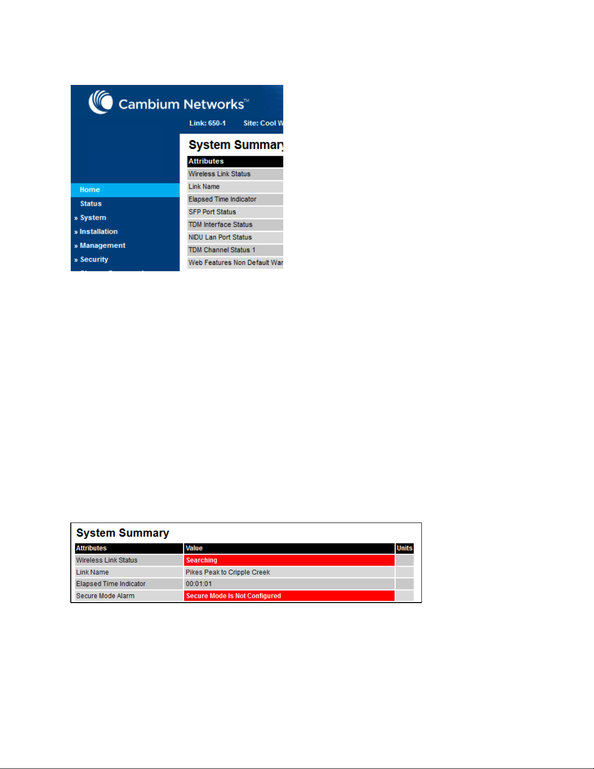
Chapter 1: Product description FIPS 140-2 mode
Figure 5
Figure 6
FIPS
140
-2
Indication of FIPS 140-2 capability
Enforced configuration in FIPS approved mode
When the PTP 700 ODU operates in the FIPS approved mode, the following configuration settings
are automatically enforced:
• Identity-based user accounts is Enabled.
• Telnet management interface is Disabled.
• SNMP control of HTTP and Telnet is Disabled.
• SNMP control of passwords is Disabled.
• TFTP client is Disabled.
Secure mode alarm
The Secure mode alarm indicates that the unit is operating in the FIPS approved mode, but that it
has not been configured correctly for FIPS 140-2 operation. The secure mode alarm appears in the
System Summary page as shown in Figure 6.
The Secure mode alarm is also displayed in the first page of the Security Wizard as shown in
Figure 7.
Secure mode alarm in the System Summary page
Page 1-55
Page 79
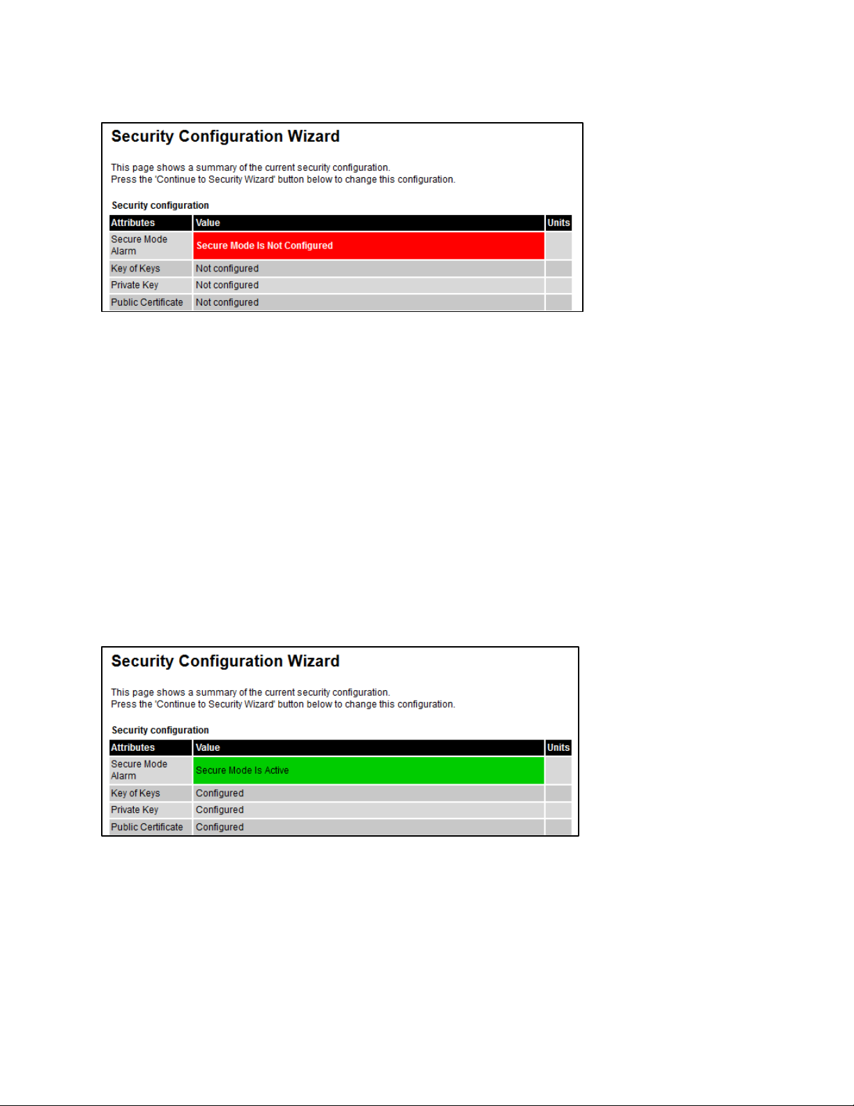
Chapter 1: Product description FIPS 140-2 mode
Figure 7
Figure 8
Secure mode alarm in the Security Wizard
Security configuration for FIPS approved mode
The security configuration for the FIPS approved mode consists of the following:
• The HTTPS/TLS management interface must be correctly configured, including:
o Key of keys (128-bit or 256-bit to match the AES license)
o Entropy (512-bit)
o Private key (2048-bit key size)
o Public key certificate (2048-bit key size)
• The HTTP management interface must be Disabled
• AES encryption must be configured and enabled at the wireless interface.
When the security configuration is completed correctly, the Secure mode alarm is cleared from the
System Summary page and the Security Wizard displays the Active state as shown in Figure 8.
Secure mode active
Page 1-56
Page 80

Chapter 1: Product description FIPS 140-2 mode
For information about…
Refer to…
For information about…
Refer to…
For information about…
Refer to…
Further reading
Cryptographic material needed for
FIPS operation
Installing license keys Software License Key page on page 6-11
Loading software images Software Upgrade page on page 6-55
Configuring the ODU for FIPS
operation
Planning for FIPS 140-2 operation on page 3-58
Configuring security for FIPS 140-2 applications on page
6-105
Exiting from the FIPS operational state
A PTP 700 ODU in the FIPS operation state can be prepared to accept new security configuration
by zeroizing critical security parameters (CSPs). The unit remains in the FIPS approved mode.
Further reading
Zeroizing the CSPs Zeroize CSPs page on page 6-104
Reverting to the standard (non-FIPS) mode
A FIPS 140-2 capable ODU can be used in standard (non-FIPS) mode by loading a standard (nonFIPS) software image and rebooting.
The critical security parameters (CSPs) are zeroized when the unit is no longer FIPS 140-2 capable.
Further reading
Exiting the FIPS approved mode Managing security on page 7-46
Page 1-57
Page 81

Chapter 2: System hardware
This chapter describes the hardware components of a PTP 700 link.
The following topics are described in this chapter:
• Outdoor unit (ODU) on page 2-2
• Power supply units (PSU) on page 2-15
• Antennas and antenna cabling on page 2-19
• Ethernet cabling on page 2-34
• PTP-SYNC unit on page 2-44
• GPS receiver on page 2-50
• Network indoor unit (NIDU) on page 2-52
Page 2-1
Page 82

Chapter 2: System hardware Outdoor unit (ODU)
Outdoor unit (ODU)
ODU description
One ODU is required for each link end. The ODU is a self-contained transceiver unit that houses
both radio and networking electronics.
Hardware platform variants
PTP 700 ODUs are available in two different hardware platform variants:
• PTP 700 Connectorized ODU
• PTP 700 Connectorized+Integrated ODU
Regional variants
Each of the PTP 700 hardware platform variants is available in three different regional variants.
The regional variants are supplied with default country licenses as follows:
• FCC/IC: “USA” country license with regulatory bands:
o 1 “5.8 GHz FCC”
o 13 “5.4 GHz FCC U-NII 2C”
o 14 “4.9 GHz Public Safety, USA/Canada”
o 38 “5.2 GHz FCC U-NII 2A”
o 82 “4.4 GHz NTIA”
o 84 “5.1 GHz FCC U-NII 1”
o 90 “5.4 GHz FCC U-NII 2C (Parabolic antenna only)”
o 91 “5.2 GHz FCC U-NII 2A (Parabolic antenna only)”
o 92 “5.1 GHz FCC U-NII 1 (Parabolic antenna only)”
• RoW: “Other” country license with regulatory bands:
o 8 “5.4 GHz unrestricted”
o 35 “5.8 GHz unrestricted”
o 61 “4.9 GHz unrestricted”
o 62 “5.2 GHz unrestricted”
o 81 “4.4 GHz NATO Band IV”
• EU: “EU” country license with regulatory band:
o 26 “5.4 GHz ETSI”
For details of how to configure the ODUs to operate with other country licenses, refer to
Generating license keys on page 6-3 and Software License Key page on page 6-11. The list of
available countries depends upon the regional variant. The list of available regulatory bands
depends on the country.
Page 2-2
Page 83

Chapter 2: System hardware Outdoor unit (ODU)
Capacity variants
Many of the PTP 700 ODU variants are available with the Lite or Full capacity license. ODUs
licensed for Lite capacity can be licensed for the Full capacity by purchase of an upgrade (see ODU
capability upgrades on page 2-8).
The ATEX/HAZLOC ODU variants are available only with the Full capacity license.
ATEX/HAZLOC variants
PTP 700 is available in ATEX/Hazloc variants for operation in locations where explosive gas
hazards exist, as defined by Hazloc (USA) and ATEX (Europe). ATEX/HAZLOC variants are similar
to the standard product except that:
• ODUs are supplied with the Full capacity license
• The frequency range is restricted to 4940 MHz to 5850 MHz
• The maximum EIRP generated by ODU is restricted to comply with the ATEX and HAZLOC
standards
PTP 700 Connectorized ODU
The PTP 700 Connectorized ODU is intended to work with separately mounted external antennas
(Figure 9). External antennas generally have higher gains than the integrated antennas, allowing
the PTP 700 to cope with more difficult radio conditions.
Page 2-3
Page 84
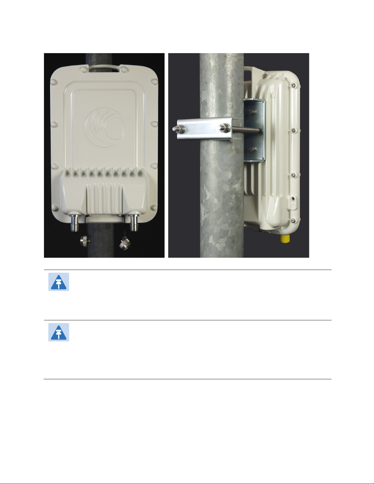
Chapter 2: System hardware Outdoor unit (ODU)
Figure 9
Note
Attention
PTP 700 Connectorized ODU (front and rear views)
To determine when to install external antennas and to calculate their impact on link
performance and regulatory limits, see Planning for connectorized units on page 3-29.
To select antennas, RF cables and connectors for connectorized units, see Antennas and
antenna cabling on page 2-19.
Pour déterminer si il est nécessaire d’installer une liaison radiofréquence avec des
antennes externes et pour calculer leur impact sur les performances de la liaison et les
limites réglementaires, voir Planning for connectorized units page 3-29.
Pour sélectionner les antennes, câbles et connecteurs RF pour les liaisons
radiofréquence sans antenne intégrée, voir Antennas and antenna cabling page 2-19.
Capacity and capability licensing
PTP 700 ODUs are available with “Lite” data throughput capability (up to 225 Mbps) or “Full” data
throughput capability (up to 450 Mbps). ODUs additionally support the following capability
upgrades (see ODU capability upgrades on page 2-8):
Page 2-4
Page 85

Chapter 2: System hardware Outdoor unit (ODU)
Table 2
Cambium description
Cambium part number
• Data throughput above 225 Mbps
• SFP port operation
• AES encryption
• Synchronous Ethernet and 1588 Transparent Clock
• TDM (E1 or T1) operation
• Group access
Full capability trial period
A full capability trial period is available for PTP 700 ODUs that are licensed for “Lite” (up to
225 Mbps) data throughput capability. This trial allows the ODU to operate with “Full” capability
(up to 450 Mbps) during a 60 day period, reverting to Lite capability afterwards. The trial period
can be started, paused and resumed from the web interface (Software License Key page on page
6-11).
Individual ODU part numbers
Order PTP 700 Connectorized ODUs from Cambium Networks (Table 4). Each of the parts listed in
Table 4 includes the following items:
• One Connectorized ODU
• One connectorized ODU mounting bracket (Figure 11).
PTP 700 Connectorized ODU (FCC) C045070B001
PTP 700 Connectorized ODU (Global) C045070B003
PTP 700 Connectorized ODU (EU) C045070B005
PTP 700 Lite Connectorized ODU (FCC) C045070B007
PTP 700 Lite Connectorized ODU (Global) C045070B009
PTP 700 Lite Connectorized ODU (EU) C045070B011
PTP 700 ATEX/HAZLOC Connectorized ODU (FCC) C045070B013
PTP 700 ATEX/HAZLOC Connectorized ODU (Global) C045070B015
PTP 700 ATEX/HAZLOC Connectorized ODU (EU) C045070B017
PTP 700 Connectorized individual ODU part numbers
ODU kit part numbers
Order PTP 700 Connectorized ODU kits from Cambium Networks (Table 5).
Each of the parts listed in Table 5 includes the following items:
• One Connectorized ODU
Page 2-5
Page 86
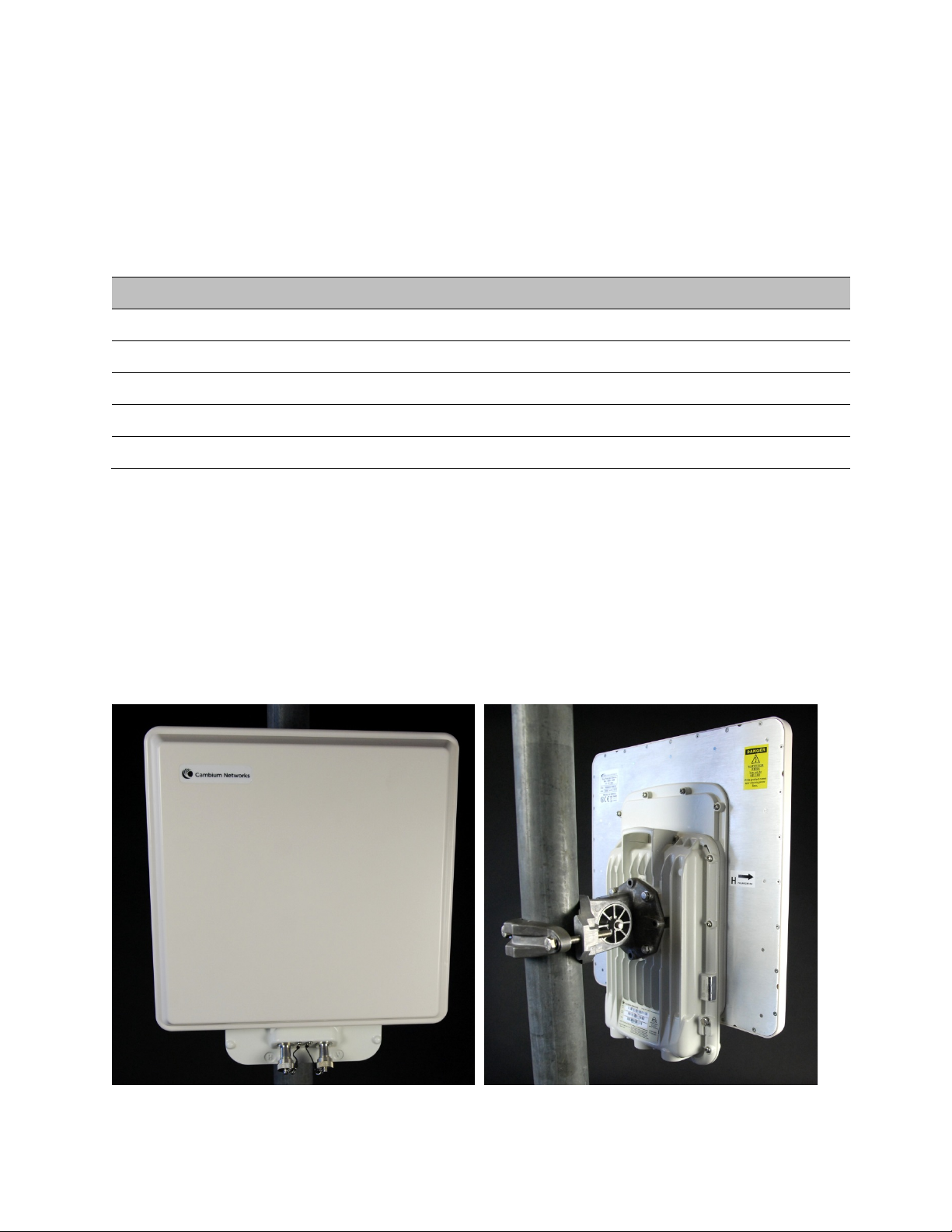
Chapter 2: System hardware Outdoor unit (ODU)
Table 3
Cambium description
Cambium part number
Figure 10
• One AC+DC Power Injector PSU.
• One line cord, either US or EU as indicated.
The PTP 700 Connectorized ODU already includes the connectorized bracket, so this is not included
separately in the kit.
PTP 700 Connectorized END (FCC) C045070H001
PTP 700 Connectorized END - US Line Cord (Global) C045070H004
PTP 700 Connectorized END - EU Line Cord (Global) C045070H007
PTP 700 Connectorized END (EU) C045070H010
PTP 700 Lite Connectorized END - US Line Cord (Global) C045070H013
PTP 700 Connectorized+Integrated ODU
The PTP 700 Connectorized+Integrated ODU provides a choice between using external antennas,
similar to the Connectorized ODU, or a 21 dBi integrated antenna (Figure 10). The integrated
antenna offers a convenient and easily-deployed solution where the additional gain of external
antennas is not needed.
ODU kit part numbers for Connectorized ODUs
PTP 700 Connectorized+Integrated ODU (front and rear views)
Page 2-6
Page 87

Chapter 2: System hardware Outdoor unit (ODU)
Note
Attention
To determine when to install external antennas and to calculate their impact on link
performance and regulatory limits, see Planning for connectorized units on page 3-29.
To select antennas, RF cables and connectors for connectorized units, see Antennas and
antenna cabling on page 2-19.
Pour déterminer si il est nécessaire d’installer une liaison radiofréquence avec des
antennes externes et pour calculer leur impact sur les performances de la liaison et les
limites réglementaires, voir Planning for connectorized units page 3-29.
Pour sélectionner les antennes, câbles et connecteurs RF pour les liaisons
radiofréquence sans antenne intégrée, voir Antennas and antenna cabling page 2-19.
Capacity and capability licensing
PTP 700 ODUs are available with “Lite” data throughput capability (up to 225 Mbps) or “Full” data
throughput capability (up to 450 Mbps). ODUs additionally support the following capability
upgrades (see ODU capability upgrades on page 2-8):
• Data throughput above 225 Mbps
• SFP port operation
• AES encryption
• Synchronous Ethernet and 1588 Transparent Clock
• TDM (E1 or T1) operation
• Group access
Full capability trial period
A full capability trial period is available for PTP 700 ODUs that are licensed for “Lite” (up to
225 Mbps) data throughput capability. This trial allows the ODU to operate with “Full” capability
(up to 450 Mbps) during a 60 day period, reverting to Lite capability afterwards. The trial period
can be started, paused and resumed from the web interface (Software License Key page on page
6-11).
Individual ODU part numbers
Order PTP 700 Connectorized+Integrated ODUs from Cambium Networks (Table 4). Each of the
parts listed in Table 4 includes the following items:
• One Connectorized+Integrated ODU.
Coonectorized+Integrated ODUs, when sold individually, are supplied without mounting brackets.
Page 2-7
Page 88

Chapter 2: System hardware Outdoor unit (ODU)
Table 4
Cambium description
Cambium part number
Table 5
Cambium description
Cambium part number
PTP 700 Connectorized+Integrated ODU (FCC) C045070B002
PTP 700 Connectorized+Integrated ODU (Global) C045070B004
PTP 700 Connectorized+Integrated ODU (EU) C045070B006
PTP 700 Lite Connectorized+Integrated ODU (FCC) C045070B008
PTP 700 Lite Connectorized+Integrated ODU (Global) C045070B010
PTP 700 Lite Connectorized+Integrated ODU (EU) C045070B012
PTP 700 ATEX/HAZLOC Connectorized+Integrated ODU (FCC) C045070B014
PTP 700 ATEX/HAZLOC Connectorized+Integrated ODU (Global) C045070B016
PTP 700 ATEX/HAZLOC Connectorized+Integrated ODU (EU) C045070B018
PTP 700 Connectorized+Integrated individual ODU part numbers
ODU kit part numbers
Order PTP 700 Connectorized+Integrated ODU kits from Cambium Networks (Table 5).
Each of the parts listed in Table 5 includes the following items:
• One Connectorized+Integrated ODU.
• One integrated ODU mounting bracket (Figure 11).
• One AC+DC Power Injector PSU.
• One line cord, either US or EU as indicated.
PTP 700 Connectorized+Integrated END (FCC) C045070H002
PTP 700 Connectorized+Integrated END - US Line Cord (Global) C045070H005
PTP 700 Connectorized+Integrated END - EU Line Cord (Global) C045070H008
PTP 700 Connectorized+Integrated END (EU) C045070H011
PTP 700 Lite Connectorized+Integrated END - US Line Cord (Global) C045070H014
ODU kit part numbers for Connectorized+Integrated ODUs
ODU capability upgrades
To upgrade a PTP 700 ODU to one or more new capabilities, order the necessary access keys from
Cambium Networks (Table 6). For details of how to install the capability upgrades, refer to
Generating license keys on page 6-3 and Software License Key page on page 6-11.
Page 2-8
Page 89

Chapter 2: System hardware Outdoor unit (ODU)
Table 6
Cambium description (*1)
Part number
Table 7
Cambium description
Cambium part number
PTP 700 128-bit AES Encryption – per END (*2) C000070K001A
PTP 700 256-bit AES Encryption – per END (*2) C000070K002A
PTP 700 Precise Network Timing Software License - per END C000070K003A
PTP 700 Group Access Software License - per END C000070K004A
PTP 700 FIPS 140-2 Upgrade including 128-bit AES - per END C000070K005A
PTP 700 FIPS 140-2 Upgrade including 256-bit AES - per END C000070K006A
PTP 700 Lite to Full Upgrade - per END C000070K008A
PTP 650/700 8-Port T1/E1 Software License (per END). C000065K049A
(*1) Order two upgrades per link.
(*2) Cambium Networks will supply AES upgrades only if there is official permission to export AES
encryption to the country of operation.
Capability upgrades available for PTP 700 Series ODUs
ODU accessories
Spare ODU port blanking plugs are available from Cambium Networks (Table 7).
PTP 650/700 Series Blanking Plug Pack (Qty 10) N000065L036
ODU accessory part numbers
ODU mounting brackets
The integrated mounting bracket (Figure 11) and connectorized mounting bracket (Figure 12) are
used to mount the PTP 700 ODUs on poles with diameters in the range 50 to 75 mm (2 to 3 inches).
The extended integrated mounting bracket (Figure 13) is used for mounting an ODU on poles with
a diameter of either 90 mm (3.5 inches) or 115 mm (4.5 inches).
The large diameter extension kit (Figure 14) is be used with the integrated bracket to mount an
ODU on a pole with diameter up to 229 mm (9.0 inches).
Before ordering ODU mounting brackets, be aware of the following:
• Individual Connectorized+Integrated ODUs are supplied without a mounting bracket (Table 4).
• Individual Connectorized ODUs are supplied with a connectorized mounting bracket (Table 4).
• ODUs in kits are supplied with an integrated or connectorized bracket, as appropriate (Table 5).
If separate ODU mounting brackets are required, order them from Cambium Networks (Table 8).
Page 2-9
Page 90

Chapter 2: System hardware Outdoor unit (ODU)
Figure 11
Figure 12
ODU mounting bracket (integrated)
ODU mounting bracket (connectorized)
Page 2-10
Page 91

Chapter 2: System hardware Outdoor unit (ODU)
Figure 13
Figure 14
Table 8
Bracket
Pole diameter
ODU variants
Bracket part
number
ODU extended integrated mounting bracket
ODU large diameter extension kit
ODU mounting bracket part numbers
Mounting bracket
(integrated)
Mounting bracket
(connectorized)
Extended integrated
mounting bracket
40 mm to 82 mm
(1.6 inches to 3.2 inches)
40 mm to 82 mm
(1.6 inches to 3.2 inches)
89 mm OR 114 mm
(3.5 inches OR 4.5 inches)
Page 2-11
PTP 700
Connectoized+Integrated
PTP 700 Connectorized
PTP 700
Connectoized+Integrated
PTP 700 Connectorized
PTP 700
N000065L031
N000065L032
N000065L030
Page 92
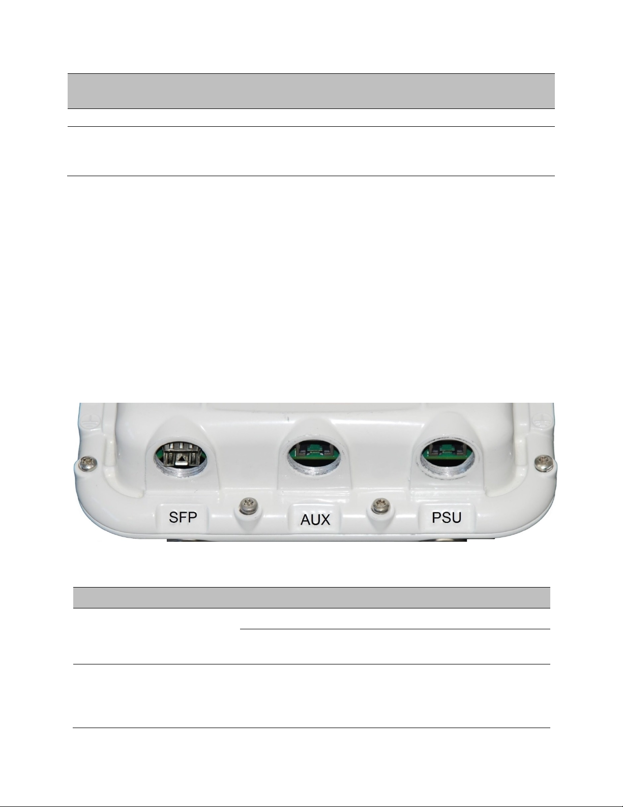
Chapter 2: System hardware Outdoor unit (ODU)
Bracket
Pole diameter
ODU variants
Bracket part
number
Figure 15
Table 9
Port name
Connector
Interface
Description
Connectoized+Integrated
Mounting bracket
(integrated) with large
diameter extension kit
89 mm to 229 mm
(3.5 inches to 9.0 inches)
PTP 700 Connectorized
PTP 700
Connectoized+Integrated
N000065L031
with
N000065L042
ODU interfaces
The PSU, AUX and SFP ports are on the rear of the ODUs (Figure 15). These interfaces are
described in Table 9. Each of the PSU, AUX and SFP ports can be configured to disable Ethernet
traffic, connected in a local loop-back between any two ports, or selected to the following services:
• Data Service
• Second Data Service
• Management Service
• Local Management Service
ODU rear interfaces
Main PSU RJ45 POE input Proprietary power over Ethernet (POE).
AUX RJ45 100/1000BASE-T
ODU rear interfaces
100/1000BASE-T
Ethernet
Ethernet with
802.3at compliant
POE out capability
Page 2-12
Management and/or data.
Auxiliary Ethernet port which can be
used, for example, to connect and
power a video camera or wireless
access point. Data and Management
Page 93
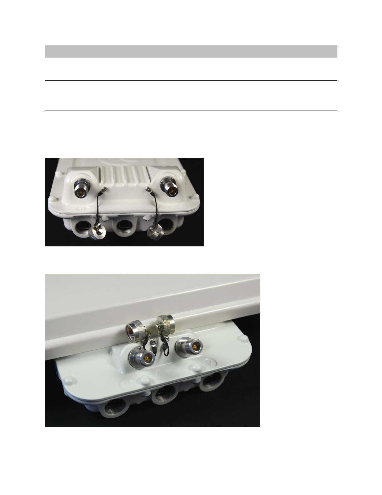
Chapter 2: System hardware Outdoor unit (ODU)
Port name
Connector
Interface
Description
Figure 16
Figure 17
Services.
SFP SFP Optical or Copper
Gigabit Ethernet
Data and Management Services.
Plug-in SFP module must be purchased
separately.
The front of the connectorized ODU (Figure 16) provides N type female connectors for RF cable
interfaces to antennas with horizontal (H) and vertical (V) polarization.
Connectorized ODU antenna interfaces
Connectorized+Integrated ODU antenna interfaces
Page 2-13
Page 94

Chapter 2: System hardware Outdoor unit (ODU)
Table 10
Category
Specification
ODU specifications
The PTP 700 ODU conforms to the specifications listed in Table 10.
Dimensions Connectorized+Integrated: 371 mm (14.6 in) x 371 mm (14.6 in) x 81 mm (3.2 in)
Weight Connectorized+Integrated:
Temperature -40°C (-40°F) to +60°C (140°F)
Wind loading 200 mph (323 kph) maximum. See ODU wind loading on page 3-14.
Humidity 100% condensing
Liquid and
particle ingress
UV exposure 10 year operational life (UL746C test evidence)
Static
discharge
ODU specifications
Connectorized: 204 mm (8.0 in) x 318 mm (12.5 in) x 90 mm (3.5 in)
Connectorized: 3.1 Kg (6.8 lbs) including bracket
IP66, IP67
See Electromagnetic compatibility (EMC) compliance on page 4-22
Page 2-14
Page 95
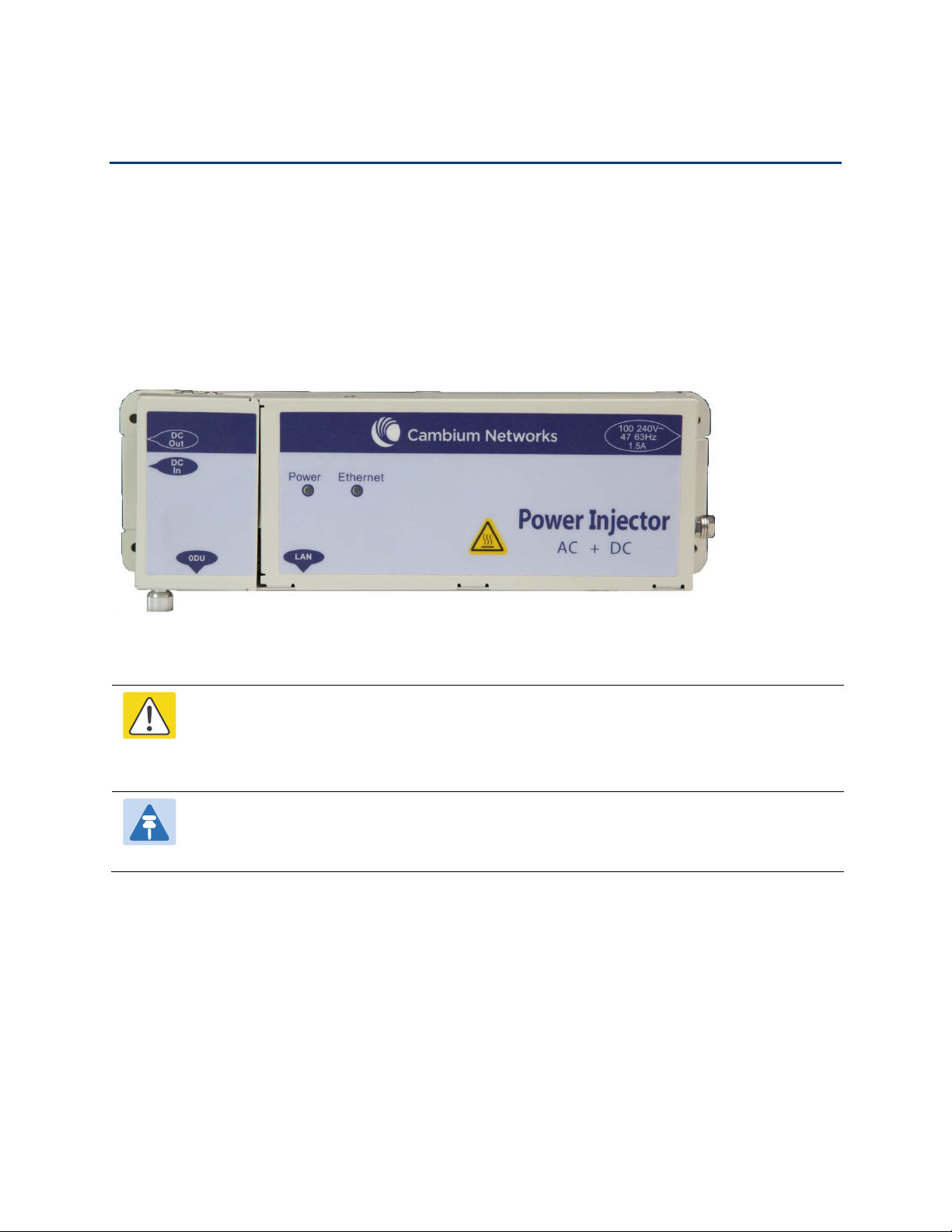
Chapter 2: System hardware Power supply units (PSU)
Figure 18
Caution
Note
Power supply units (PSU)
PSU description
The AC+DC Power Injector is an indoor unit that is connected to the ODU and network terminating
equipment using Cat5e cable with RJ45 connectors. It is also plugged into an AC or DC power
supply so that it can inject Power over Ethernet (POE) into the ODU. Choose one of the following
PSUs (Figure 18):
AC+DC Power Injector
The PSU ODU ports are designed to connect only to PTP 700 ODUs, PTP-SYNC units,
NIDUs or LPUs. Do not connect any other equipment, as damage may occur.
Do not connect the PIDU Plus PTP 300/500/600 Series to the PTP 700 ODU or LPU.
Each of the ODU kits listed in Table 5 includes one PSU and one US or EU line cord as
stated in the Cambium description.
Page 2-15
Page 96
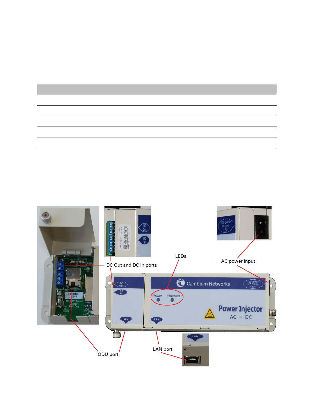
Chapter 2: System hardware Power supply units (PSU)
Table 11
Cambium description
Cambium part number
Figure 19
PSU part numbers
Order PSUs and (for AC power) line cords from Cambium Networks (Table 11).
PTP 650/700 AC+DC Enhanced Power Injector C000065L002
US Line Cord Fig 8 N000065L003
UK Line Cord Fig 8 N000065L004
EU Line Cord Fig 8 N000065L005
Australia Line Cord Fig 8 N000065L006
Power supply component part numbers
AC+DC Enhanced Power Injector interfaces
The AC+DC Enhanced Power Injector interfaces are shown in Figure 19 and described in Table 12.
AC+DC Enhanced Power Injector interfaces
Page 2-16
Page 97

Chapter 2: System hardware Power supply units (PSU)
Table 12
Interface
Function
Table 13
Category
Specification
100-240V 47-63Hz 1.5A AC power input (main supply).
DC In Alternative DC power supply input.
DC Out DC power output to a second PSU (for power supply redundancy) or
ODU RJ45 socket for connecting Cat5e cable to ODU.
LAN RJ45 socket for connecting Cat5e cable to network.
Power (green) LED Power supply detection
Ethernet (yellow) LED Ethernet traffic detection
AC+DC Enhanced Power Injector interface functions
to a NIDU.
PSU specifications
The PTP 700 AC+DC Enhanced Power Injector conforms to the specifications listed in Table 13.
AC+DC Enhanced Power Injector specifications
Dimensions 250 mm (9.75 in) x 40 mm (1.5 in) x 80 mm (3 in)
Weight 0.864 Kg (1.9 lbs)
Temperature -40°C (-40°F) to +60°C (140°F)
Humidity 0 to 90% non-condensing
Waterproofing Not waterproof
AC Input 90-264 V AC, 47-60 Hz
Alternative DC Input 37-60 V DC
DC Output Voltage
AC Input connector IEC-320-C8
DC Output current 1.7A
Efficiency Better than 84%
Over Current Protection Hiccup current limiting, trip point set between 120% to
For mains input: 58 V, +2V, -0V
For DC input: Output voltage at maximum rated output
current, not more than 1.5 V below the DC input voltage.
Maximum length of DC output cable: 3 meters.
150% of full load current
Page 2-17
Page 98

Chapter 2: System hardware Power supply units (PSU)
Category
Specification
Hold up time At least 20 milliseconds
Power factor Better than 0.9
Page 2-18
Page 99

Chapter 2: System hardware Antennas and antenna cabling
Note
Table 14
Cambium description
Cambium part number
Note
Antennas and antenna cabling
Antenna requirements
Each connectorized ODU requires one external antenna (normally dual-polar), or if spatial diversity
is required, each ODU requires two antennas. These antennas are not supplied by Cambium
Networks.
For connectorized units operating in the USA or Canada 4.9 GHz, 5.1 GHz, 5.2 GHz, 5.4 GHz or
5.8 GHz bands, choose external antennas from those listed in FCC and IC approved antennas on
page 2-20. Do not install any other antennas. For links in other countries, the listed antennas are
advisory, not mandatory.
To determine when to install connectorized units and to calculate their impact on link
performance and regulatory limits, see Planning for connectorized units on page 3-29.
RF cable and connectors
RF cable of generic type LMR-400 is required for connecting the ODU to the antenna. N type male
connectors are required for connecting the RF cables to the connectorized ODU. Two connectors
are required per ODU. Use weatherproof connectors, preferably ones that are supplied with
adhesive lined heat shrink sleeves that are fitted over the interface between the cable and
connector. Order CNT-400 RF cable and N type male connectors from Cambium Networks (Table
14).
50 Ohm Braided Coaxial Cable - 75 meter 30010194001
50 Ohm Braided Coaxial Cable - 500 meter 30010195001
RF Connector, N, Male, Straight for CNT-400 Cable 09010091001
RF cable and connector part numbers
To select the correct connectors for the antenna end of the RF cable, refer to the
antenna manufacturer’s instructions.
Page 2-19
Page 100

Chapter 2: System hardware Antennas and antenna cabling
Caution
Caution
Antenna accessories
Connectorized ODUs require the following additional components:
• Cable grounding kits: Order one cable grounding kit for each grounding point on the antenna
cables. Refer to Lightning protection unit (LPU) and grounding kit on page 2-37 for
specifications and part numbers.
• Self-amalgamating and PVC tape: Order these items to weatherproof the RF connectors.
• Lightning arrestors: When the connectorized ODU is mounted indoors, lightning arrestors (not
PTP 700 LPUs) are required for protecting the antenna RF cables at building entry. One arrestor
is required per antenna cable. One example of a compatible lightning arrestor is the
Polyphaser LSXL-ME or LSXL (not supplied by Cambium Networks).
FCC and IC approved antennas
For connectorized units operating in the USA or Canada, choose external antennas from Table 15
(4.9 GHz), Table 16 (5.1 GHz – USA only), Table 17 (5.2 GHz), Table 18 (5.4 GHz) or Table 19
(5.8 GHz). These are approved by the FCC for use with the product and are constrained by the
following limits for single- or dual-polarization parabolic dish antennas:
• 4.9 GHz – 36.0 dBi per polarization or antenna.
• 5.1 GHz - 34.5 dBi per polarization or antenna.
• 5.2 GHz - 34.9 dBi per polarization or antenna.
• 5.4 GHz - 34.9 dBi per polarization or antenna.
• 5.8 GHz - 37.7 dBi per polarization or antenna.
Details of the regulatory bands are provided in Table 52 on page 3-22.
Antennas not included in these tables are strictly prohibited for use with the PTP 700
in the specified bands.
This radio transmitter (IC certification number 109AO-50650) has been approved by
Industry Canada to operate with the antenna types listed below with the maximum
permissible gain and required antenna impedance for each antenna type indicated.
Antenna types not included in this list, having a gain greater than the maximum gain
indicated for that type, are strictly prohibited for use with this device.
Page 2-20
 Loading...