

Cambium Networks PTP 820C, 820C Assured Installation Manual

INSTALLATION GUIDE
PTP 820C and PTP
820C Assured
System Release 10.0

phn-3962 004v000
Accuracy
While reasonable efforts have been made to assure the accuracy of this document, Cambium Networks
assumes no liability resulting from any inaccuracies or omissions in this document, or from use of the
information obtained herein. Cambium reserves the right to make changes to any products described
herein to improve reliability, function, or design, and reserves the right to revise this document and to
make changes from time to time in content hereof with no obligation to notify any person of revisions
or changes. Cambium does not assume any liability arising out of the application or use of any
product, software, or circuit described herein; neither does it convey license under its patent rights or
the rights of others. It is possible that this publication may contain references to, or information about
Cambium products (machines and programs), programming, or services that are not announced in
your country. Such references or information must not be construed to mean that Cambium intends to
announce such Cambium products, programming, or services in your country.
Copyrights
This document, Cambium products, and 3rd Party software products described in this document may
include or describe copyrighted Cambium and other 3rd Party supplied computer programs stored in
semiconductor memories or other media. Laws in the United States and other countries preserve for
Cambium, its licensors, and other 3rd Party supplied software certain exclusive rights for copyrighted
material, including the exclusive right to copy, reproduce in any form, distribute and make derivative
works of the copyrighted material. Accordingly, any copyrighted material of Cambium, its licensors, or
the 3rd Party software supplied material contained in the Cambium products described in this
document may not be copied, reproduced, reverse engineered, distributed, merged or modified in any
manner without the express written permission of Cambium. Furthermore, the purchase of Cambium
products shall not be deemed to grant either directly or by implication, estoppel, or otherwise, any
license under the copyrights, patents or patent applications of Cambium or other 3rd Party supplied
software, except for the normal non-exclusive, royalty free license to use that arises by operation of
law in the sale of a product.
Restrictions
Software and documentation are copyrighted materials. Making unauthorized copies is prohibited by
law. No part of the software or documentation may be reproduced, transmitted, transcribed, stored in a
retrieval system, or translated into any language or computer language, in any form or by any means,
without prior written permission of Cambium.
License Agreements
The software described in this document is the property of Cambium and its licensors. It is furnished
by express license agreement only and may be used only in accordance with the terms of such an
agreement.
High Risk Materials
Cambium and its supplier(s) specifically disclaim any express or implied warranty of fitness for any
high risk activities or uses of its products including, but not limited to, the operation of nuclear
facilities, aircraft navigation or aircraft communication systems, air traffic control, life support, or
weapons systems (“High Risk Use”). Any High Risk is unauthorized, is made at your own risk and you
shall be responsible for any and all losses, damage or claims arising out of any High Risk Use.
© 2018 Cambium Networks Limited. All Rights Reserved.

phn-3962 004v000
Page i
Contents
About This Installation Guide ................................................................................................................ 1
Contacting Cambium Networks .................................................................................................... 1
Purpose ........................................................................................................................................... 2
Cross references ............................................................................................................................. 2
Feedback ......................................................................................................................................... 2
Problems and warranty ........................................................................................................................ 3
Reporting problems ....................................................................................................................... 3
Repair and service .......................................................................................................................... 3
Hardware warranty ........................................................................................................................ 3
Security advice ...................................................................................................................................... 4
Warnings, cautions, and notes ............................................................................................................ 5
Warnings ......................................................................................................................................... 5
Cautions .......................................................................................................................................... 5
Notes ............................................................................................................................................... 5
Caring for the environment .................................................................................................................. 6
In EU countries ............................................................................................................................... 6
In non-EU countries ....................................................................................................................... 6
Chapter 1: Before You Start ........................................................................................................... 1-1
Important Notes ................................................................................................................................. 1-2
Safety Precautions & Declared Material .......................................................................................... 1-3
General Equipment Precautions ................................................................................................ 1-3
Allgemeine Vorsichtsmaßnahmen für die Anlage ................................................................... 1-5
Pre-installation Instructions .............................................................................................................. 1-6
Packing ......................................................................................................................................... 1-6
Transportation and Storage ....................................................................................................... 1-6
Unpacking .................................................................................................................................... 1-6
Inspection ..................................................................................................................................... 1-6
PTP 820 Assured Platform ................................................................................................................. 1-7
Chapter 2: Product Hardware Description ..................................................................................... 2-1
PTP 820C Hardware Overview .......................................................................................................... 2-2
PTP 820C Interfaces ..................................................................................................................... 2-3
MultiCore Mediation Devices (MCMD) ............................................................................................ 2-4
PoE Injector ......................................................................................................................................... 2-6
PoE Injector Interfaces ................................................................................................................ 2-6
System Components ......................................................................................................................... 2-8
Adaptors and Installation Kits ......................................................................................................... 2-10
Adaptors and Installation Kits .................................................................................................. 2-10

Contents
phn-3962 004v000
Page ii
Antenna Circ Adaptors.............................................................................................................. 2-12
PoE Injector ................................................................................................................................ 2-12
Antenna Connection ........................................................................................................................ 2-13
Power Specs ..................................................................................................................................... 2-15
Electrical Requirements ............................................................................................................ 2-15
Important Notes ........................................................................................................................ 2-15
Environmental Specifications .................................................................................................. 2-15
Chapter 3: Cable Installation and Grounding ................................................................................ 3-1
Minimum and Maximum Cable Diameter ....................................................................................... 3-2
Cable Grounding ................................................................................................................................ 3-3
Grounding the PTP 820C Unit. ................................................................................................... 3-6
Grounding for MultiCore Mediation Devices............................................................................ 3-8
Power Source .............................................................................................................................. 3-8
Surge Protection .............................................................................................................................. 3-10
Available Cable Options .................................................................................................................. 3-11
Fiber Optic Cables ..................................................................................................................... 3-11
DC Cable and Connector........................................................................................................... 3-11
Cables for MIMO Connections ................................................................................................. 3-12
Ethernet Cable and Specifications ........................................................................................... 3-12
Outdoor Ethernet Cable Specifications ................................................................................... 3-13
Outdoor DC Cable Specifications ............................................................................................ 3-14
Securing the Cables ......................................................................................................................... 3-16
Special Instructions for use of Glands ........................................................................................... 3-17
General Installation Procedure ................................................................................................ 3-18
Connecting an Optical Fiber Cable and SFP .................................................................................. 3-23
Connecting a DC Power Cable ........................................................................................................ 3-27
Connecting the Ethernet Cable ....................................................................................................... 3-30
Preparing the Ethernet Cable and Plug-in Field ..................................................................... 3-30
Preparing the Ethernet Cable Already Assembled ................................................................. 3-34
Connection of Ethernet Cable to PTP 820C ............................................................................. 3-35
Management Connection for 4x4 MIMO and 1+1/2+2 HSB Configurations ............................... 3-37
Preparing a MIMO/Protection Signaling Cable ...................................................................... 3-37
Connecting the MIMO/Protection Splitters and Protection Signaling Cable ....................... 3-38
Chapter 4: PoE Injector Installation and Connection ..................................................................... 4-1
PoE Injector Cable Connection.......................................................................................................... 4-2
PoE Injector Grounding ..................................................................................................................... 4-3
PoE Injector 19” Rack Installation ..................................................................................................... 4-4
List of Items ................................................................................................................................. 4-4
Required Tools ............................................................................................................................ 4-4
Procedure ..................................................................................................................................... 4-5
PoE Injector ETSI Rack Installation ................................................................................................... 4-7
List of Items ................................................................................................................................. 4-7
Required Tools ............................................................................................................................ 4-7

Contents
phn-3962 004v000
Page iii
Procedure ..................................................................................................................................... 4-7
Chapter 5: Generic Installation Procedures ................................................................................... 5-1
General Notes Concerning All Installation Procedures .................................................................. 5-2
Torque Requirements ........................................................................................................................ 5-3
PTP 820C DC Pole Mount Procedure ................................................................................................ 5-4
List of Items ................................................................................................................................. 5-4
Required Tools ............................................................................................................................ 5-4
Installation Procedure ................................................................................................................. 5-4
6-13 GHz Installation Procedure ................................................................................................. 5-5
Remote Mount Installation for Single Polarization with an Remote Mount kit ............................ 5-6
List of Items ................................................................................................................................. 5-6
Required Tools ............................................................................................................................ 5-6
6-13 GHz Installation Procedure ................................................................................................. 5-7
15-38 GHz Installation Procedure ............................................................................................. 5-10
Management Connection for MIMO and Protection Configurations .......................................... 5-13
Preparing a MIMO/Protection Signaling Cable ...................................................................... 5-13
Connecting a MIMO/Protection Signaling Cable .................................................................... 5-13
Connecting a MIMO/Protection Splitter .................................................................................. 5-14
Chapter 6: Installation Procedures per Configuration Type .......................................................... 6-1
MultiCore 2+0 Dual Polarization Direct Mount ................................................................................ 6-2
List of Items ................................................................................................................................. 6-2
Required Tools ............................................................................................................................ 6-2
Insertion Loss .............................................................................................................................. 6-3
Procedure ..................................................................................................................................... 6-3
MultiCore 2+0 Dual Polarization Remote Mount ............................................................................. 6-5
List of Items ................................................................................................................................. 6-5
Required Tools ............................................................................................................................ 6-6
Insertion Loss .............................................................................................................................. 6-6
Common Installation ................................................................................................................... 6-6
6-13 GHz ....................................................................................................................................... 6-8
15-38 GHz ..................................................................................................................................... 6-9
MultiCore 2+0 Single Polarization Direct Mount ........................................................................... 6-11
List of Items ............................................................................................................................... 6-11
Required Tools .......................................................................................................................... 6-11
Insertion Loss ............................................................................................................................ 6-11
Procedure ................................................................................................................................... 6-12
MultiCore 2+0 Single Polarization Remote Mount ........................................................................ 6-13
List of Items ............................................................................................................................... 6-13
Required Tools .......................................................................................................................... 6-13
Insertion Loss ............................................................................................................................ 6-14
6-13 GHz ..................................................................................................................................... 6-15
15-38 GHz ................................................................................................................................... 6-17
MultiCore 2+2 HSB Double Polarization Direct Mount ................................................................. 6-19

Contents
phn-3962 004v000
Page iv
List of Items ............................................................................................................................... 6-19
Required Tools .......................................................................................................................... 6-19
Insertion Loss ............................................................................................................................ 6-20
Procedure ................................................................................................................................... 6-20
MultiCore 2+2 HSB Double Polarization Remote Mount .............................................................. 6-23
List of Items ............................................................................................................................... 6-23
Required Tools .......................................................................................................................... 6-23
Insertion Loss ............................................................................................................................ 6-24
Common Installation ................................................................................................................. 6-24
6-13 GHz ..................................................................................................................................... 6-27
15-38 GHz ................................................................................................................................... 6-29
MultiCore 2+2 HSB Single Polarization Direct Mount .................................................................. 6-31
List of Items ............................................................................................................................... 6-31
Required Tools .......................................................................................................................... 6-31
Insertion Loss ............................................................................................................................ 6-31
Procedure ................................................................................................................................... 6-33
MultiCore 2+2 HSB Single Polarization Remote Mount ............................................................... 6-36
List of Items ............................................................................................................................... 6-36
Required Tools .......................................................................................................................... 6-36
Insertion Loss ............................................................................................................................ 6-37
6-13 GHz ..................................................................................................................................... 6-37
15-38 GHz ................................................................................................................................... 6-41
2 x MultiCore 2+0 Dual Polarization Direct Mount ........................................................................ 6-44
List of Items ............................................................................................................................... 6-44
Required Tools .......................................................................................................................... 6-44
Insertion Loss ............................................................................................................................ 6-45
Procedure ................................................................................................................................... 6-45
2 x MultiCore 2+0 Dual Polarization Remote Mount ..................................................................... 6-47
List of Items ............................................................................................................................... 6-47
Required Tools .......................................................................................................................... 6-47
Insertion Loss ............................................................................................................................ 6-48
Common Installation Procedure .............................................................................................. 6-48
6-13 GHz ..................................................................................................................................... 6-50
15-38 GHz ................................................................................................................................... 6-52
2 x MultiCore 2+0 Single Polarization Direct Mount ..................................................................... 6-54
List of Items ............................................................................................................................... 6-54
Required Tools .......................................................................................................................... 6-54
Insertion Loss ............................................................................................................................ 6-54
Procedure ................................................................................................................................... 6-55
2x2 LoS MIMO Direct Mount........................................................................................................... 6-57
List of Items ............................................................................................................................... 6-57
Required Tools .......................................................................................................................... 6-57
Insertion Loss ............................................................................................................................ 6-57

Contents
phn-3962 004v000
Page v
Procedure ................................................................................................................................... 6-58
2x2 LoS MIMO Remote Mount ....................................................................................................... 6-62
List of Items ............................................................................................................................... 6-62
Required Tools .......................................................................................................................... 6-62
Insertion Loss ............................................................................................................................ 6-62
6-13 GHz ..................................................................................................................................... 6-63
15-38 GHz ................................................................................................................................... 6-65
4x4 LoS MIMO Direct Mount........................................................................................................... 6-67
List of Items ............................................................................................................................... 6-67
Required Tools .......................................................................................................................... 6-67
Insertion Loss ............................................................................................................................ 6-68
Procedure ................................................................................................................................... 6-69
4+0 Dual Polarization, 2+2HSB Single/Dual Polarization Direct Mount ...................................... 6-71
List of Items ............................................................................................................................... 6-71
Required Tools .......................................................................................................................... 6-71
Procedure ................................................................................................................................... 6-71
4+0 Dual Polarization, 2+2HSB Dual Polarization Remote Mount ............................................... 6-73
List of Items ............................................................................................................................... 6-73
Required Tools .......................................................................................................................... 6-73
Common Installation ................................................................................................................. 6-73
6-13GHz ...................................................................................................................................... 6-74
15-38 GHz ................................................................................................................................... 6-76
2+2 HSB Single Polarization Remote Mount ................................................................................. 6-78
List of Items ............................................................................................................................... 6-78
Required Tools .......................................................................................................................... 6-78
6-13GHz ...................................................................................................................................... 6-79
1+1 HSB-SD ...................................................................................................................................... 6-82
List of Items ............................................................................................................................... 6-82
Required Tools .......................................................................................................................... 6-82
6-13GHz ...................................................................................................................................... 6-82
15-42GHz .................................................................................................................................... 6-84
AFR 1+0 Hub Site ............................................................................................................................. 6-86
List of Items ............................................................................................................................... 6-86
Required Tools .......................................................................................................................... 6-86
Insertion Loss ............................................................................................................................ 6-87
Common Installation ................................................................................................................. 6-88
6-13 GHz ..................................................................................................................................... 6-89
15-38 GHz ................................................................................................................................... 6-91
Chapter 7: Mediation Device Losses .............................................................................................. 7-0
Chapter 8: Acceptance & Commissioning Procedures .................................................................. 8-2
Site Acceptance Procedure ............................................................................................................... 8-3
Site Acceptance Checklist Notes ...................................................................................................... 8-7
Radio Link Commissioning Procedure ............................................................................................. 8-9

Contents
phn-3962 004v000
Page vi
Scope ............................................................................................................................................ 8-9
Commissioning Test ................................................................................................................... 8-9
PTP 820 Commissioning Log .......................................................................................................... 8-11

Contents
phn-3962 004v000
Page vii
List of Figures
Figure 1 PTP 820C Rear View (Left) and Front View (Right) ................................................................ 2-2
Figure 2 Cable Gland Construction ........................................................................................................ 2-2
Figure 3 PTP 820C Interfaces .................................................................................................................. 2-3
Figure 4 Splitter ....................................................................................................................................... 2-4
Figure 5 OMT ........................................................................................................................................... 2-5
Figure 6 PoE Injector ............................................................................................................................... 2-6
Figure 7 PoE Injector Ports ..................................................................................................................... 2-7
Figure 8 System Components ................................................................................................................ 2-8
Figure 9 Grounding cable ....................................................................................................................... 3-3
Figure 10 Ethernet cable design .......................................................................................................... 3-13
Figure 11 Glands ................................................................................................................................... 3-17
Figure 12 Removing glands ................................................................................................................. 3-18
Figure 13 Transparent Pressure Windows. ............................................................................................ 5-2
Figure 14 MIMO/Protection signaling cable 1..................................................................................... 5-13
Figure 15 MIMO/Protection signaling cable 2..................................................................................... 5-14
Figure 16 MIMO/Protection signaling cable 3..................................................................................... 5-15
Figure 17 MultiCore 2+0 Dual Polarization Remote Mount ................................................................. 6-5
Figure 18 MultiCore 2+0 Single Polarization Remote Mount ............................................................ 6-13
Figure 19 MultiCore 2+2 HSB Double Polarization Direct Mount ..................................................... 6-19
Figure 20 MultiCore 2+2 HSB Double Polarization Remote Mount .................................................. 6-23
Figure 21 MultiCore 2+2 HSB Single Polarization Direct Mount ....................................................... 6-31
Figure 22 MultiCore 2+2 HSB Single Polarization Remote Mount ................................................... 6-36
Figure 23 2 x MultiCore 2+0 Dual Polarization Direct Mount ............................................................ 6-44
Figure 24 2 x MultiCore 2+0 Dual Polarization Remote Mount ......................................................... 6-47
Figure 25 2 x MultiCore 2+0 Single Polarization Direct Mount ......................................................... 6-54
Figure 26 2x2 LoS MIMO Direct Mount ............................................................................................... 6-57
Figure 27 2x2 LoS MIMO Remote Mount ............................................................................................ 6-62
Figure 28 4x4 Los MIMO Direct Mount ................................................................................................ 6-67
Figure 29 2+2 HSB Single Polarization Remote Mount ..................................................................... 6-78

Contents
phn-3962 004v000
Page viii
List of Tables
Table 1 MCMD type ................................................................................................................................. 2-4
Table 2 Adaptors and Installation kits for 6 to 18 GHz ....................................................................... 2-10
Table 3 Adaptors and Installation kits for 23 to 38 GHz ..................................................................... 2-10
Table 4 Remote Mount – 6 to 15 GHz .................................................................................................. 2-11
Table 5 Remote Mount – 18 to 38 GHz ................................................................................................ 2-11
Table 6 Antenna circ. Adaptors for 6 to 18GHz .................................................................................. 2-12
Table 7 Antenna circ. Adaptors for 23 to 38 GHz ............................................................................... 2-12
Table 8 PoE Injector .............................................................................................................................. 2-12
Table 9 Other antenna types ................................................................................................................ 2-13
Table 10 Cable Grounding Kit ................................................................................................................. 3-3
Table 11 Fiber Optic cables part numbers .......................................................................................... 3-11
Table 12 DC Cable and Connector part numbers ............................................................................... 3-11
Table 13 Cables for MIMO connections part numbers ...................................................................... 3-12
Table 14 Ethernet cable part numbers ................................................................................................ 3-12
Table 15 Ethernet cable color code ..................................................................................................... 3-13
Table 16 Outdoor Ethernet cable specifications – Electircal requirements. .................................... 3-13
Table 17 Outdoor DC cable specifications – Electrical Requirements .............................................. 3-14
Table 18 Ethernet cable part numbers ................................................................................................ 3-17
Table 19 Materials for preparing Ethernet Data Cables ...................................................................... 3-30
Table 20 Required items for PoE Injector 19” rack installation ........................................................... 4-4
Table 21 Required items for PoE Injector ETSI rack installation ......................................................... 4-7
Table 22 DC Pole Mount part numbers .................................................................................................. 5-4
Table 23 Required items for Remote mount Installation single polarization .................................... 5-6
Table 24 Required items for MultiCore 2+0 Dual Polarization Direct Mount ..................................... 6-2
Table 25 Insertion loss for MultiCore 2+0 Dual Polarization Direct Mount ......................................... 6-3
Table 26 List of items for MultiCore 2+0 Dual Polarization Remote Mount........................................ 6-5
Table 27 Insertion loss for MultiCore 2+0 Dual Polarization Remote Mount .................................... 6-6
Table 28 Required item for MultiCore 2+0 Single Polarization Direct Mount................................... 6-11
Table 29 Insertion loss for MultiCore 2+0 Single Polarization Direct Mount .................................... 6-11
Table 30 Required item for MultiCore 2+0 Single Polarization Remote Mount .............................. 6-13
Table 31 Insertion loss for MultiCore 2+0 Single Polarization Remote Mount ................................ 6-14
Table 32 Required items for MultiCore 2+2 HSB Double Polarization Direct Mount ...................... 6-19
Table 33 Insertion loss for MultiCore 2+2 HSB Double Polarization Direct Mount ......................... 6-20
Table 34 Required items for MultiCore 2+2 HSB Double Polarization Remote Mount .................... 6-23
Table 35 Insertion loss for MultiCore 2+2 HSB Double Polarization Remote Mount ....................... 6-24
Table 36 Required items for MultiCore 2+2 HSB Single Polarization Direct Mount ....................... 6-31
Table 37 Insertion loss for MultiCore 2+2 HSB Single Polarization Direct Mount .......................... 6-31
Table 38 Required items for MultiCore 2+2 HSB Single Polarization Remote Mount .................... 6-36
Table 39 Insertion loss for MultiCore 2+2 HSB Single Polarization Remote Mount ....................... 6-37
Table 40 Required items for 2 x MultiCore 2+0 Dual Polarization Direct Mount ............................. 6-44
Table 41 Insertion loss for 2 x MultiCore 2+0 Dual Polarization Direct Mount ................................. 6-45

Contents
phn-3962 004v000
Page ix
Table 42 Required items for MultiCore 2+0 HSB Dual Polarization Remote Mount ....................... 6-47
Table 43 Insertion loss for MultiCore 2+0 Dual Polarization Remote Mount .................................. 6-48
Table 44 Required items for 2 x MultiCore 2+0 Single Polarization Direct Mount .......................... 6-54
Table 45 Insertion loss for 2 x MultiCore 2+0 Single Polarization Direct Mount ............................. 6-54
Table 46 Required items for 2x2 LoS MIMO Direct Mount ............................................................... 6-57
Table 47 Insertion loss for 2x2 LoS MIMO Direct Mount .................................................................. 6-57
Table 48 Required items for 2x2 LoS MIMO Remote Mount ............................................................ 6-62
Table 49 Insertion loss for 2x2 LoS MIMO Remote Mount ............................................................... 6-62
Table 50 Required items for 4x4 LoS MIMO Direct Mount ............................................................... 6-67
Table 51 Insertion loss for 4x4 LoS MIMO Direct Mount .................................................................. 6-68
Table 52 Required items for 4+0 Dual Polarization, 2+2 HSB Single/Dual Polarization Direct Mount 6-
71
Table 53 Required items for 4+0 Dual Polarization, 2+2HSB Dual Polarization Remote Mount ..... 6-73
Table 54 Required items for 2+2 HSB Single Polarization Remote Mount ...................................... 6-78
Table 55 Required items for 1+1 HSB-SD ............................................................................................ 6-82
Table 56 Required items 1+0 Hub Site ................................................................................................. 6-86
Table 57 Insertion Loss for AFR 1+0 Hub Site ..................................................................................... 6-87
Table 58 Mediation device losses .......................................................................................................... 7-0

phn-3962 004v000
Page 1
About This Installation Guide
This guide describes the PTP 820C installation procedures and provides additional information
concerning system parts and frequency bands.
This guide contains the following chapters:
• Chapter 1 : Before You Start
• Chapter 2 : Product Hardware Description
• Chapter 3 : Cable Installation and Grounding
• Chapter 4 : PoE Injector Installation and Connection
• Chapter 5 : Generic Installation Procedures
• Chapter 6 : Installation Procedures per Configuration Type
• Chapter 7 : Acceptance and Commisioning Procedures
Contacting Cambium Networks
Support website:
https://support.cambiumnetworks.com
Main website:
http://www.cambiumnetworks.com
Sales enquiries:
solutions@cambiumnetworks.com
Support enquiries:
https://support.cambiumnetworks.com
Repair enquiries
https://support.cambiumnetworks.com
Telephone number list:
http://www.cambiumnetworks.com/support/contact-support
Address:
Cambium Networks Limited,
Linhay Business Park,
Eastern Road,
Ashburton,
Devon, UK,
TQ13 7UP

Chapter 1: Before You Start
Problems and warranty
phn-3962 004v000
Page 2
Purpose
Cambium Networks Point-To-Point (PTP) documents are intended to instruct and assist personnel
in the operation, installation and maintenance of the Cambium PTP equipment and ancillary
devices. It is recommended that all personnel engaged in such activities be properly trained.
Cambium Networks disclaims all liability whatsoever, implied or express, for any risk of damage,
loss or reduction in system performance arising directly or indirectly out of the failure of the
customer, or anyone acting on the customer's behalf, to abide by the instructions, system
parameters, or recommendations made in this document.
Cross references
References to external publications are shown in italics. Other cross references, emphasized in
blue text in electronic versions, are active links to the references.
This document is divided into numbered chapters that are divided into sections. Sections are not
numbered, but are individually named at the top of each page, and are listed in the table of
contents.
Feedback
We appreciate feedback from the users of our documents. This includes feedback on the structure,
content, accuracy, or completeness of our documents. Send feedback to
support@cambiumnetworks.com.

Chapter 1: Before You Start
Problems and warranty
phn-3962 004v000
Page 3
Problems and warranty
Reporting problems
If any problems are encountered when installing or operating this equipment, follow this
procedure to investigate and report:
1
Search this document and the software release notes of supported releases.
2
Visit the support website.
3
Ask for assistance from the Cambium Networks product supplier.
4
Gather information from affected units, such as any available diagnostic downloads.
5
Escalate the problem by emailing or telephoning support.
Repair and service
If unit failure is suspected, obtain details of the Return Material Authorization (RMA) process from
the support website.
Hardware warranty
Cambium Networks’s standard hardware warranty is for one (1) year from date of shipment from
Cambium Networks or a Cambium distributor. Cambium Networks warrants that hardware will
conform to the relevant published specifications and will be free from material defects in material
and workmanship under normal use and service. Cambium Networks shall within this time, at its
own option, either repair or replace the defective product within thirty (30) days of receipt of the
defective product. Repaired or replaced product will be subject to the original warranty period but
not less than thirty (30) days.
To register PTP products or activate warranties, visit the support website. For warranty assistance,
contact the reseller or distributor.
Caution
Using non-Cambium Networks parts for repair could damage the equipment or void
warranty. Contact Cambium Networks for service and repair instructions.
Portions of Cambium Networks equipment may be damaged from exposure to
electrostatic discharge. Use precautions to prevent damage.

Chapter 1: Before You Start
Security advice
phn-3962 004v000
Page 4
Security advice
Cambium Networks systems and equipment provide security parameters that can be configured
by the operator based on their particular operating environment. Cambium recommends setting
and using these parameters following industry recognized security practices. Security aspects to
be considered are protecting the confidentiality, integrity, and availability of information and
assets. Assets include the ability to communicate, information about the nature of the
communications, and information about the parties involved.
In certain instances Cambium Networks makes specific recommendations regarding security
practices, however the implementation of these recommendations and final responsibility for the
security of the system lies with the operator of the system.
Chapter 1: Before You Start
Warnings, cautions, and notes
phn-3962 004v000
Page 5
Warnings, cautions, and notes
The following describes how warnings and cautions are used in this document and in all
documents of the Cambium Networks document set.
Warnings
Warnings precede instructions that contain potentially hazardous situations. Warnings are used to
alert the reader to possible hazards that could cause loss of life or physical injury. A warning has
the following format:
Warning
Warning text and consequence for not following the instructions in the warning.
Cautions
Cautions precede instructions and are used when there is a possibility of damage to systems,
software, or individual items of equipment within a system. However, this damage presents no
danger to personnel. A caution has the following format:
Caution
Caution text and consequence for not following the instructions in the caution.
Notes
A note means that there is a possibility of an undesirable situation or provides additional
information to help the reader understand a topic or concept. A note has the following format:
Note
Note text.

Chapter 1: Before You Start
Caring for the environment
phn-3962 004v000
Page 6
Caring for the environment
The following information describes national or regional requirements for the disposal of
Cambium Networks supplied equipment and for the approved disposal of surplus packaging.
In EU countries
The following information is provided to enable regulatory compliance with the European Union
(EU) directives identified and any amendments made to these directives when using Cambium
Networks equipment in EU countries.
Disposal of Cambium Networks equipment
European Union (EU) Directive 2002/96/EC Waste Electrical and Electronic Equipment (WEEE)
Do not dispose of Cambium Networks equipment in landfill sites. For disposal instructions, refer to
http://www.cambiumnetworks.com/support/weee-compliance
Disposal of surplus packaging
Do not dispose of surplus packaging in landfill sites. In the EU, it is the individual recipient’s
responsibility to ensure that packaging materials are collected and recycled according to the
requirements of EU environmental law.
In non-EU countries
In non-EU countries, dispose of Cambium Networks equipment and all surplus packaging in
accordance with national and regional regulations.

phn-3962 004v000
Page 1-1
Chapter 1: Before You Start
Cambium Networks PTP 820C represents a new generation of radio technology, capable of high bit
rates and longer reach and suitable for diverse deployment scenarios.
PTP 820C is a MultiCore system that utilizes parallel radio signal processing in a compact, alloutdoor device combining radio, baseband, and Carrier Ethernet functionality to offer a future
proof solution for PTP connectivity applications.
PTP 820C supports cutting edge capacity-boosting techniques, such as LoS MIMO, QPSK to 2048
QAM, and Header De-Duplication, to offer a high capacity solution for every network topology and
every site configuration.
This chapter includes:
• Important Notes
• Safety Precautions & Declared Material
• Pre-installation Instructions
• PTP 820 Assured Platform

Chapter 1: Before You Start
Important Notes
phn-3962 004v000
Page 1-2
Important Notes
• For the warranty to be honored, install the unit in accordance with the instructions in this
manual.
• Any changes or modifications of equipment not expressly approved by the manufacturer could
void the user’s authority to operate the equipment and the warranty for such equipment.
• PTP 820C is intended for installation in a restricted access location.
• PTP 820C must be installed and permanently connected to protective earth by qualified service
personnel in accordance with applicable national electrical codes.
Chapter 1: Before You Start
Safety Precautions & Declared Material
phn-3962 004v000
Page 1-3
Safety Precautions & Declared Material
General Equipment Precautions
Caution
To avoid malfunctioning or personnel injuries, equipment or accessories/kits/plug-in
unit installation, requires qualified and trained personnel. Changes or modifications
not expressly approved by Cambium Networks could void the user's authority to
operate the equipment.
Caution
Where special cables, shields, adapters and grounding kits are supplied or described
in this manual, these items must be used, to comply with the FCC regulations.
Caution
Use of controls, adjustments, or performing procedures other than those specified
herein, may result in hazardous radiation exposure.
Caution
When working with a PTP 820C, note the following risk of electric shock and energy
hazard:
Disconnecting one power supply disconnects only one power supply module. To
isolate the unit completely, disconnect all power supplies.
Caution
Machine noise information order - 3. GPSGV, the highest sound pressure level
amounts to 70 dB (A) or less, in accordance with ISO EN 7779.
Anti Static
Static electricity may cause body harm, as well as harm to electronic components
inside the device. Anyone responsible for the installation or maintenance of the PTP
820C must use an ESD Wrist Strap. ESD protection measures must be observed when
touching the unit. To prevent damage, before touching components inside the device,
all electrostatic must be discharged from both personnel and tools.
Caution
In Norway and Sweden:
Chapter 1: Before You Start
Safety Precautions & Declared Material
phn-3962 004v000
Page 1-4
Equipment connected to the protective earthing of the building installation through
the mains connection or through other equipment with a connection to protective
earthing – and to a cable distribution system using coaxial cable, may in some
circumstances create a fire hazard. Connection to a cable distribution system has
therefore to be provided through a device providing electrical isolation below a certain
frequency range (galvanic isolator, see EN 60728-11).
Utstyr som er koplet til beskyttelsesjord via nettplugg og/eller via annet jordtilkoplet
utstyr – og er tilkoplet et kabel-TV nett, kan forårsake brannfare. For å unngå dette skal
det ved tilkopling av utstyret til kabel-TV nettet installeres en galvanisk isolator
mellom utstyret og kabel- TV nettet.
Utrustning som är kopplad till skyddsjord via jordat vägguttag och/eller via annan
utrustning och samtidigt är kopplad till kabel-TV nät kan i vissa fall medfőra risk főr
brand. Főr att undvika detta skall vid anslutning av utrustningen till kabel-TV nät
galvanisk isolator finnas mellan utrustningen och kabel-TV nätet.
Caution
Précautions générales relatives à l'équipement
Caution
L’utilisation de commandes ou de réglages ou l'exécution de procédures autres que
celles spécifiées dans les présentes peut engendrer une exposition dangereuse aux
rayonnements.
Caution
L’usage de PTP 820C s’accompagne du risque suivant d'électrocution et de danger
électrique : le débranchement d'une alimentation électrique ne déconnecte qu'un
module d'alimentation électrique. Pour isoler complètement l'unité, il faut débrancher
toutes les alimentations électriques.
Caution
Bruit de machine d’ordre - 3. GPSGV, le plus haut niveau de pression sonore s'élève à
70 dB (A) au maximum, dans le respect de la norme ISO EN 7779.

Chapter 1: Before You Start
Safety Precautions & Declared Material
phn-3962 004v000
Page 1-5
Allgemeine Vorsichtsmaßnahmen für die Anlage
Caution
Wenn andere Steuerelemente verwendet, Einstellungen vorgenommen oder
Verfahren durchgeführt werden als die hier angegebenen, kann dies gefährliche
Strahlung verursachen.
Caution
Beachten Sie beim Arbeiten mit PTP 820C das folgende Stromschlag- und
Gefahrenrisiko: Durch Abtrennen einer Stromquelle wird nur ein.
Caution
Stromversorgungsmodul abgetrennt. Um die Einheit vollständig zu isolieren, trennen
Sie alle Stromversorgungen ab.
Maschinenlärminformations-Verordnung - 3. GPSGV, der höchste Schalldruckpegel
beträgt 70 dB(A) oder weniger gemäß EN ISO 7779.

Chapter 1: Before You Start
Pre-installation Instructions
phn-3962 004v000
Page 1-6
Pre-installation Instructions
Packing
The equipment must be packed and sealed in moisture absorbing bags.
Transportation and Storage
The equipment cases are prepared for shipment by air, truck, railway and sea, suitable for
handling by forklift trucks and slings. The cargo must be kept dry during transportation, in
accordance with ETS 300 019-1-2, Class 2.3. For sea-transport, deck-side shipment is not permitted.
Carrier-owned cargo containers must be used.
It is recommended that the equipment be transported to the installation site in its original packing
case.
If intermediate storage is required, the packed equipment must be stored in a dry and cool
environment, and out of direct sunlight, in accordance with ETS 300 019-1-1, Class 1.2.
Unpacking
The equipment is packed in sealed plastic bags and moisture absorbing bags are inserted. Any
separate sensitive product, i.e printed boards, are packed in anti-static handling bags. The
equipment is further packed in special designed cases.
Marking is done according to standard practice unless otherwise specified by customers. The
following details should be marked:
• Customers address
• Contract No
• Site name (if known)
• Case No
Inspection
Check the packing lists and ensure that correct parts numbers quantities of goods have arrived.
Inspect for any damage on the cases and equipment. Report any damage or discrepancy to
Cambium Networks support by e-mailing to support@cambiumnetworks.com.

Chapter 1: Before You Start
PTP 820 Assured Platform
phn-3962 004v000
Page 1-7
PTP 820 Assured Platform
PTP 820 Assured platform enhances network reliability and security, ensuring that mission-critical
networks maintain availability, and protecting the confidentiality and integrity of their users’ data.
The PTP 820 Assured platform is compliant with FIPS 140-2, including:
• Compliance with FIPS 140-2 specifications for cryptography module.
• FIPS 140-2 Level 2 physical security.
• AES-256 encryption (FIPS 197) over radio links.
The PTP 820 Assured platform also provides:
• Secured communication and protocols for management interface.
• Centralized user authentication management via RADIUS.
• Advanced identity management and password policy enforcement.
• Security events log.
• Secure product architecture and development.
The following products are included in the PTP 820 Assured platform:
• PTP 820C Assured
• PTP 820S Assured
• PTP 820G Assured
Note
PTP 820 Assured is supported with certain versions of the release. To determine
whether a specific release version supports PTP 820 Assured, check the Release
Notes for the current system release.

phn-3962 004v000
Page 2-1
Chapter 2: Product Hardware Description
This chapter describes the hardware components of the PTP 820C product. This chapter consists of
the following sections:
• PTP 820C Hardware Overview
• MultiCore Mediation Devices (MCMD)
• PoE Injector
• System Components
• Adaptors and Installation Kits
• Antenna Connection
• Power Specs
Chapter 2: Product Hardware Description
PTP 820C Hardware Overview
phn-3962 004v000
Page 2-2
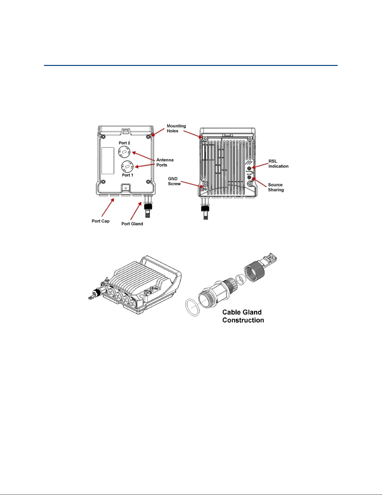
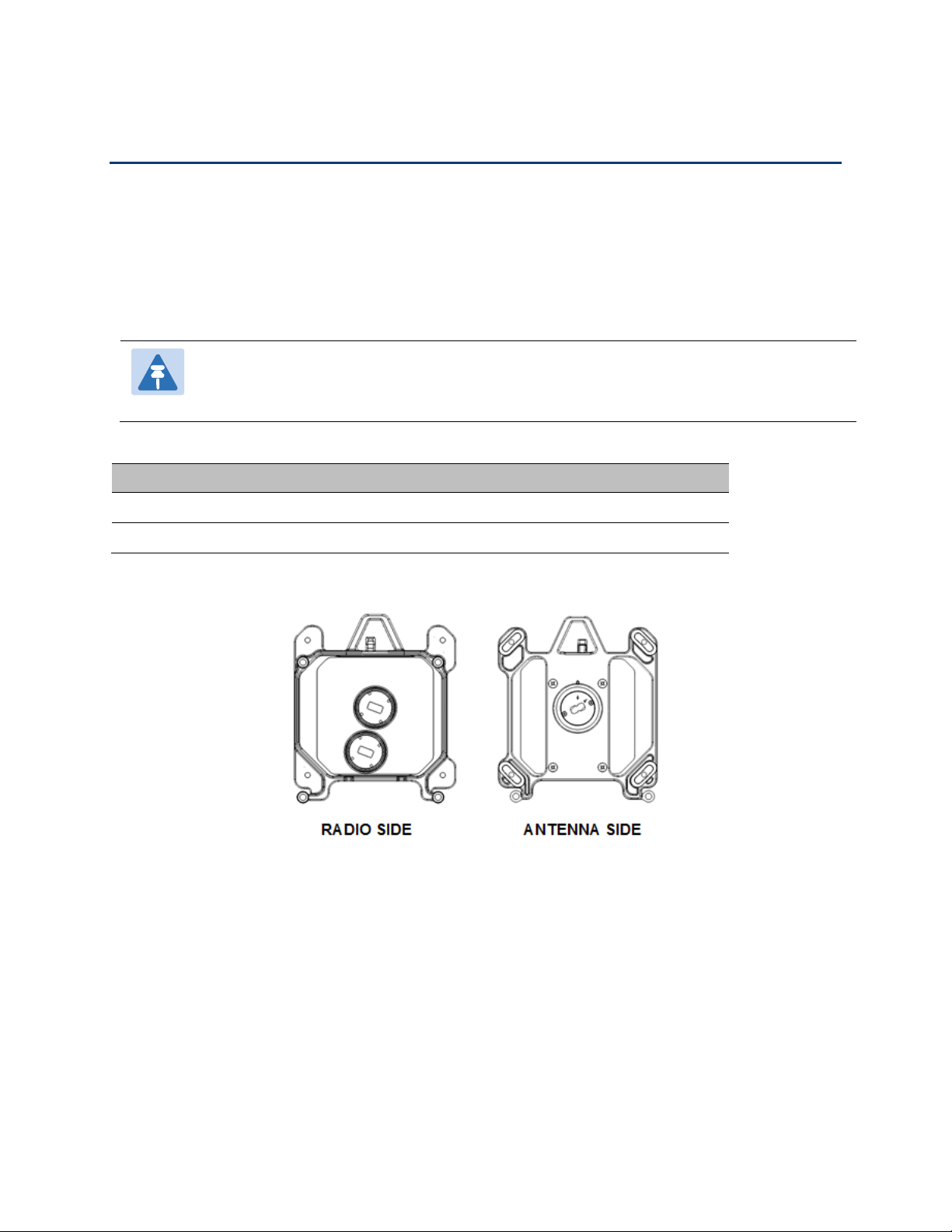
PTP 820C Hardware Overview
PTP 820C features an all-outdoor MultiCore architecture consisting of a single unit directly
mounted on the antenna.
Figure 1 PTP 820C Rear View (Left) and Front View (Right)
Figure 2 Cable Gland Construction
Chapter 2: Product Hardware Description
PTP 820C Hardware Overview
phn-3962 004v000
Page 2-3
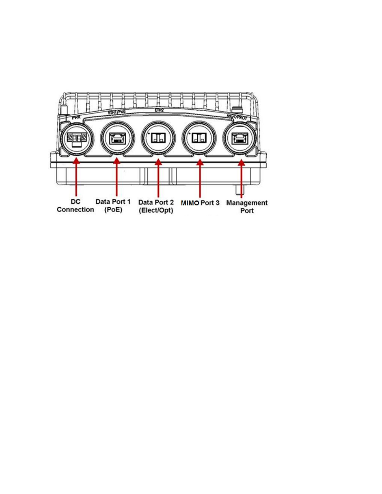
PTP 820C Interfaces
Figure 3 PTP 820C Interfaces
• Data Port 1 for GbE traffic:
o Electric: 10/100/1000Base-T. Supports PoE.
o Optical: 1000Base-SX (or X-LX-ZX/XD)
• Data Port 2 for GbE traffic:
o Electric: 10/100/1000Base-T
o Optical: 1000Base-SX (or X-LX-ZX/XD)
• Data Port 3 - Reserved for MIMO Use Only
• Power interface (-48VDC)
• Management Port: 10/100Base-T
• 2 RF Interfaces : Standard interface per frequency band
• RSL interface: BNC connector
• Source sharing: TNC connector
• Grounding screw
Chapter 2: Product Hardware Description
MultiCore Mediation Devices (MCMD)
phn-3962 004v000
Page 2-4
MultiCore Mediation Devices (MCMD)
The MultiCore Mediation Devices (MCMD) are designed to offer a simple and compact solution for
a direct mount installation of the dual-carrier PTP 820C on a standard RFU-C antenna.
PTP 820C is equipped with two antenna ports, which mandates the use of the following MCMDs
for direct mount connections. The specific MCMDs depend on the configuration.
The following table describes some of the available MCMDs. For a full list of components, see
System Components on page 2-8.
Note
MCMDs are not grounded. To add grounding, the MCMD can be connected to the PTP
820C using a Grounding Jumper.
Table 1 MCMD type
MCMD type
Functionality
Splitter
Combines the two carriers using the same polarization
OMT
Combines the two carriers on alternate polarizations (H,V)
Figure 4 Splitter
Chapter 2: Product Hardware Description
MultiCore Mediation Devices (MCMD)
phn-3962 004v000
Page 2-5
Figure 5 OMT
Chapter 2: Product Hardware Description
PoE Injector
phn-3962 004v000
Page 2-6
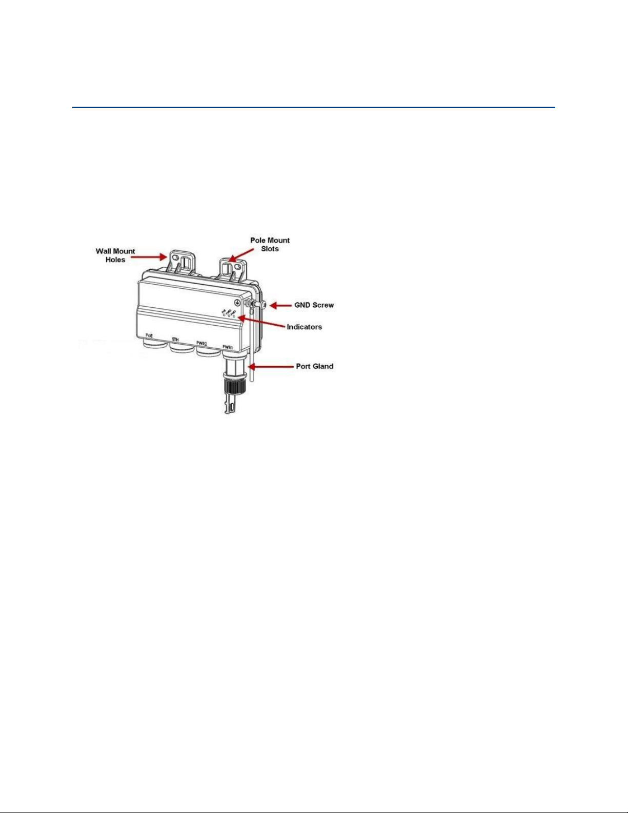
PoE Injector
The PoE injector is an outdoor unit which can be mounted on a wall, pole, or indoor rack.
Each PoE Injector kit includes the following items:
• PoE injector
• 2 DC power connectors
Figure 6 PoE Injector
The PoE Injector model available:
• N000082L022A PTP 820 PoE Injector all outdoor, redundant DC input, +24VDC support –
Includes two DC power ports with power input ranges of ±(18-60)V each.
PoE Injector Interfaces
• Power-Over-Ethernet (PoE) Port
• GbE Data Port supporting 10/100/1000Base-T
• DC Power Port 1 ±(18-60)V or ±(40-60)V
• DC Power Port 2 ±(18-60)V
• Grounding screw
 Loading...