

Page 1
Page 2

Installation… ……… …… …… ……… …… …… …… … …… …… …… ……… …… …02
Additional information… ……… …… …… ……… …… …… …… … …… ……04
General operations… ……… …… …… ……… …… …… …… … …… …… …… …05
Radio operations …… ……… …… …… …… … …… …… …… ……… …… …… …09
USB/ SD operations ……… …… …… …… ……… …… …… ……… …… …… …10
RDS operations … …… …… …… ……… …… …… ……… …… …… …… ……… …11
Specification……… …… …… …… … …… …… …… ……… …… …… …… … …… ……12
01
Page 3
IN STALL AT ION
PRECAUTIONS
Cho os e the moun ti ng locat ion whe re the un it wi ll no t int er fer e wi th the normal
drivi ng functio n of the drive r.
Bef or e finally ins talling t he uni t, connect the wiring tem por arily and make su re
it is all c onnected u p properly a nd the unit an d the system w ork proper ly.
Use onl y the parts incl uded with the uni t to ens ure pr oper inst all ation. The use
of unau thorized p arts can cau se ma lfunc tions.
Con sul t wi th your ne ar est deal er if ins tal lation req ui res the dr illing of ho les or
other mo dificat ions of the ve hicle.
Insta ll the unit wh ere it does no t get in the dri ver's way an d cannot inj ure the
passe nger if ther e is a sudden st op. Like an eme rgency st op.
Avoid inst alling the u nit where it w ould be subj ect to high te mperatur e, such
as from d irect sunl ight, or fro m hot air, form t he heater, or w here it woul d be
subje ct to dust, di rt or excess ive vibrat ion.
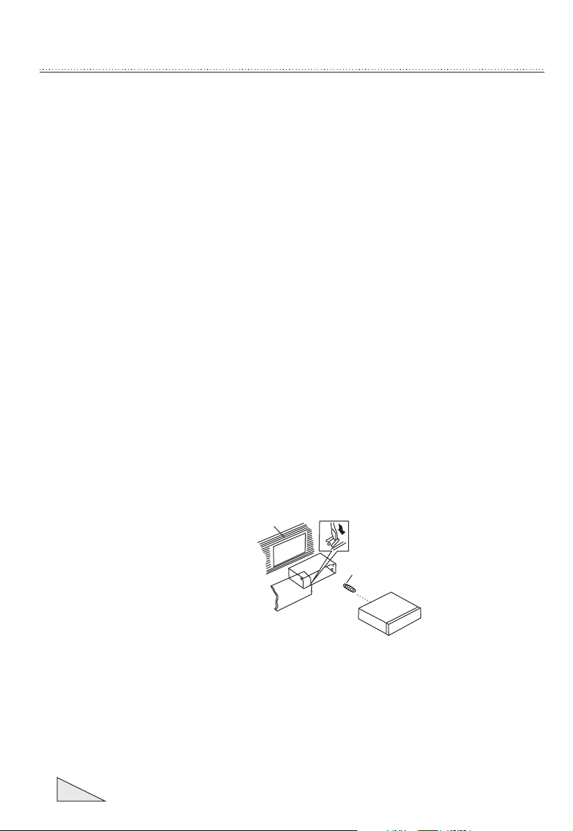
DIN FRONT-MOUNT (Me thod A)
Insta lling the un it
1. Dash board
2. Hold er
After i nserting t he holder in to
the das hboard, se lect the
appro priate tab a ccording t o
the thi ckness of th e dashboar d
mater ial and bend t hem
inwar ds to secure t he holder in
(Fig. 1 )
place .
3. Scre w
02
1
(Fig. 1 )
2
3
Page 4
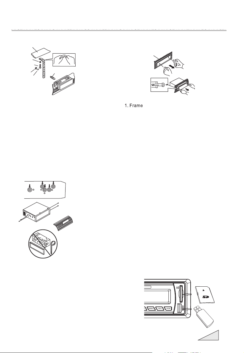
IN STALL AT ION
1
7
4
2
3
(F ig.2)
6
5
1. Dash board
2. Nut (5 mm)
3. Spri ng Washe r
4. Scre w (5 x 25mm)
5. Scre w
6. Stra p
Be sure t o use the stra p to
secur e the back of th e unit in
place . The s trap can be be nt by
hand to t he desired a ngle.
7. Plai n Washer
2
2
3
Rem oving t he unit
1
2
3
(F ig.3)
2. In ser t fingers in to the groov e in the
front of frame and pul l out to remove
the fram e. (When reatt achi ng the
frame , point the si de wi th a groo ve
dow nw ards and att ach it. )
3. Leve r
Insert the levers supp lied with t he
uni t int o the grooves at both sides of
the uni t and show n in f igure unti l they
cli ck . Pullin g th e levers mak es possible
to re mo ve th e unit fro m th e dashb oard.
Faste ning the uni t to the facto ry
radio m ounting br acket:
1. Sele ct a positio n where the sc rew
holes o f the bracke t and the
screw h oles of the ma in unit
becom e aligned (a re fitted) , and
tight en the screw s at 2 places on
each si de. Use eith er truss scr ews
(5 x 5mm) o r flush surf ace screws
(4 x 5mm)
2. Scre w
3. Dash board or Con sole
INPUT THE SD CARD
The SD ob lique angl e keeps
Right ward expos ure, put int o
the SD sl ot and press i t again
to ejec t.
DIN REAR-MOUNT (Met hod B)
Insta llation us ing the scre w holes on
the sid es of the unit
03
Page 5
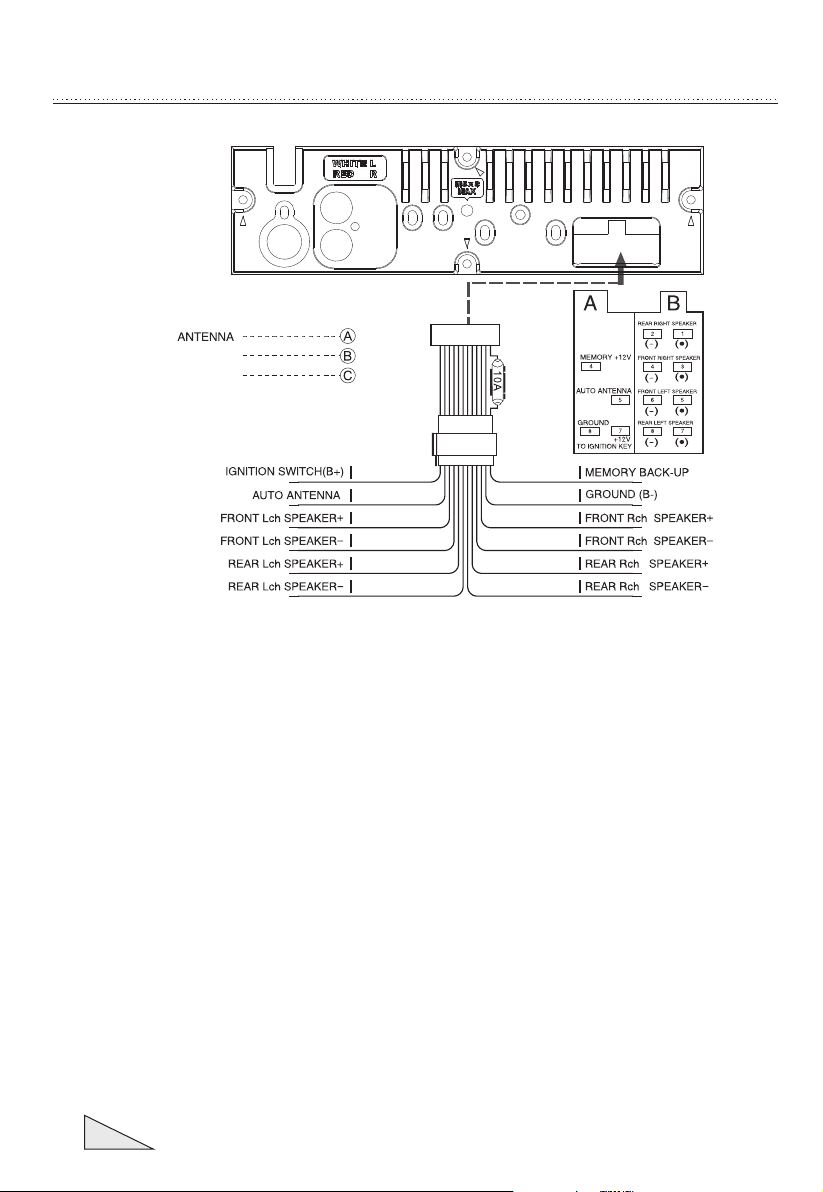
REAR Rch LINE OUT
REAR Lch LINE OUT
AD DITIO NA L INFORMA TI ON
C
A
B
RED YEL LOW
BLU E
WHI TE
WHI TE/B LAC K
GRE EN
GRE EN/B LAC K
BLA CK
GRE Y
GRE Y/B LACK
VIO LET
VIO LET /BLA CK
04
Page 6

GE NERAL O PE RATIONS
FRONT PANEL LAYOUT
2
1
17
3
8
4
19
22
17
Pre ss Rele ase But ton to De tacha ble
10
9
7
6
12 13
1118
14
5
21
20
15
16
1. Po wer B utton
2. Vol ume /Sel Butto n
3. Mo de sw itch
4. Di spl ay Button
5. LC D Dis play
6. Re set B utton
7. Ba nd sw itch
/ID3 se lect
8. Tun e Seek & Tra ck forward B utton
9. Tun e Seek & Tra ck reverse B utton
10.A uto maticall y memory sto ring
11. Play/pau se & Preset Bu tton 1
12.I ntr o & Preset But ton 2
13.R epe at & Preset Bu tton 3
14.R and om & Preset Bu tton 4
15.P res et Button 5
16.P res et Button 6
17.R ele ase Button
18. Mut e Button
19.
AUX IN JA CK
20.
USB con necter
21.
SD/MM C slot
22.
Flash ing LED
05
Page 7

GE NERAL O PE RATIONS
GENERAL OPERATIONS
ON/OFF
Press P OWER butto n (1) to turn on t he unit. Pre ss it more tha n 1 sec ond to turn off.
SOUND ADJUSTMENT
Tur n on (2) can adj ust the desi red volume q uality.
Press S EL butto n (2) will cha nge in the fol lowing ord er.
Optio n:
VOL
(Vo lum e) ( Bass) (T rebl e) (B ala nce)
VOLUME
Adjus t volume lev el by using (2) kno b. Turn the VOL knob to lef t to
decre ase the soun d level, tur n the VOL kn ob to right to i ncrease th e sou nd leve l.
Note: The un it is initia lly set to vol ume mode.
BASS
Press V OL/SEL but ton(2) one t ime. Adjust b ass level by u sing VOL/SEL (2) Knob.
TREBLE
Press V OL/SEL but ton(2) two t imes. Adjus t treble lev el by using VO L/ SEL(2)
Knob
BAS TRE BAL FAD
(F ade r)
VOL/ SEL
BALANCE
Press V OL/SEL but ton(2) thr ee times. Adj ust sound ba lance betw een left and
right s peakers by u sing VOL/SEL (2)Knob .
FADER (optional)
Press S EL butto n(2) four ti mes. Adjust s ound balan ce between f ron t and rea r
speak ers by using V OL/SEL(2)K nob.
DSP OFF
06
Page 8

GE NERAL O PE RATIONS
No te : On R emote Contr ol
AREA SE TUP
In Radi o mode. Pres s SEL button fo r several se conds. LCD show from
BEEP ON AREA USA /EUR. At AREA USA /EUR. You can us e VOL +/- to sele ct the
AREA fre quency.
will be
07
Page 9

GE NERAL O PE RATIONS
SELECT MODE
By pres sing this bu tton(3) to g o to different fu nction mod e:
- Tuner (r adio)
- USB
to go to th is mode USB de vice must be c onnected .
- Memor y Card
to go to th is mode must b e have a Memor y Card in.
- AUX in put
DISPLAY
Press D ISP button (4) to o perate as th e conversi on of each dis pla y mode as f oll ow:
- Time is di splayed fo r 5sec when DI SP ke y is pressed , and it retur ns to i ts
previ ous displa y ( Folder, Fil e name...) u nless DISP key is p ressed aga in.
3) From t he clock mod e, when DISP Key is p ressed for l onger than 1 sec ,
clock m ode switch es to clock Ad justing mo de and the clo ck display
begin s flashing . At this time c lock can be ch anged by pre ssing ( +/- ),
or the EN CODER VOLU ME.
LIQUID CRYSTAL DISPLAY
Exhib it current f requency a nd activat ed functio ns on the disp lay ( 5).
RESET
RESET butt on (6) is plac ed on the hous ing and must b e activate d with eithe r
a ball po int pen or thi n metal obje ct. (Do not us e sharp obje ct to avoid da mag ing
the uni t.) The RESET button ( 6) is to be acti vated for th e fol lowin g rea sons:
- Initi al install ation of the u nit when all w iring is com pleted.
- All the fu nction but tons do not op erate.
- Error s ymbol on the d isplay.
08
Page 10

RA DIO OPE RA TIONS
BAND SELECTION
At tune r mode, pres s BAND butto n (7) to selec t the desire d ban d. Th e
recep tion band wi ll change in t he followi ng order:
STATION S ELECTION
STATION S ELECTION
Durin g radio mode , Press “SEE K ” or “SEEK ”bu ttons shor tly t o autom ati cally
searc h a station, P ress “SEEK ” o r “SEEK ” butt ons more tha n 1 sec ond is
opera ted as manua l turning mo de.
AUTOM ATICAL LY MEMORY STORING & PROGRAM SC ANNING
- Automa tically Me mory Stori ng
Press AM S(MP3) but ton (10) for s everal sec onds, the ra dio search es fr om the
curre nt frequen cy and check s the signal s trength un til one cycl e sea rch is finis hed.
And the n 6 stronges t stations a re stored in to the corre spo nding p res et number
butto n.
- Progr am Scannin g
Press AM S(MP3) but ton (10) sho rtly to scan p reset stat ion . When th e AMS mo de is
carry o ut, “INT” ap pear on LCD di splay, the unit sc an each stor ed st ation f or 5 se conds,
you als o can press th e correspo nding numb er button or AM S button. Your d esi red
stati on wi ll star t playing.
STATION S TORING
Press p reset butt on (11~16)
RADIO M ODE.
M1 ~ M6
- PRESE T MEM ORY is loa ded when key i s pressed fo r less than 1 se cond.
- PRESE T MEM ORY is sav ed when key is p ressed for l onger than 1 s ec.
09
Page 11

US B/SD OPE RA TIONS
USB/SD FLASH MP3 Play ing:
PLAY / PAU SE
Press b utton (11) pause f unction Music t rack play ti me
flash es. Press it a gain to resu m palying, p ress it more t han 1 second i s TOP fu nctio n.
INT
Press b utton (12) : During INT RO ON, INT indica tor comes on a nd be gins
Playi ng the first 1 0sec of each s ong, until t he last song i s played. It b egi ns
playi ng the entir e track from w here INT starte d
RPT
Press p reset butt on (13): Flash play mo de : REPEAT ON / OFF is act ivated.
When R EPE AT ON, R PT IN DIC ATOR come s on and repea ts
music t rack.
RDM
Press p reset butt on (14): and
each tr ack of disc is p layed in ram dom instea d of normal or der.
SELEC T TRACKS
Durin g USB/SD opera tion, pres s SEEK " " butto n or " "
butto n to move to the p revious tr ack or the fol lowing tra ck, Tr ack num ber s hows
on display. Duri ng / , hold to fast
rever se or fast for ward. Musi c play start s from when yo u rel ease th e but ton.
USB SD SEEK " " (8 ) button or SE EK " " (9)
is acti vated. INDIC ATOR
the cur rent
Durin g RANDOM ON, R DM INDICATOR is turne d on
(8) SEEK (9)
Press p reset butt on (15- 16) :
- MP3 MOD E : 10 TR ACK UP / DOWN is acti vated.
When th e total trac k is 10 or less, K EY is i nactivat ed.
10
Page 12

RD S OPERA TI ONS
11
Page 13

SP ECIFI CA TION
General
Power Sup ply Requi rements: DC 14. 4V, Negat ive Ground
Load Impe dance:
Maximum O utput Power:
Chassis D imensions: 178 x 130x 50mm (W x D x H)
Current D rain: 5A
4 ohms
7W x 4(CH)
Tone Controls
Bass (at 10 0Hz): +10dB / -10 dB
Tre ble (at 10K ): +10dB / -10 dB
USB/SD MUSIC Player
Signal to N oise Ratio: More than 6 0dB
Channel S eparation: More than 6 0dB
Frequen cy Response: 20Hz - 20KH z
FM Radio
Frequen cy Coverage (MHz): 87.5 - 10 8MHz
IF : 10.7MHz
Sensiti vity (S/N-30dB): 12dBu
Stereo Se paration: >30dB
Remarks:
Specifications su bject to change witho ut notice
12
Page 14

 Loading...