

Page 1
Operating Instructions
Bedienungsanleitung
Instructions de Service
Type 1150
Process and Program controller
Page 2

We reserve the right to make technical changes without notice.
Technische Änderungen vorbehalten.
Sous resérve de modification techniques.
© 2004 Bürkert Werke GmbH & Co.
Operating Instructions 0507/02_EU-EN_00804664
Page 3

Table of Contents
Process and Program Controller
Type 1150
C
ONTENTS
GENERAL NOTES .................................................................................................................................................................................................................................5
Typographical conventions ............................................................................................................................................................................................ 6
Safety instructions
Protection from damage by electrostatic charging
Scope of delivery
Warranty conditions
................................................................................................................................................................................................................... 6
......................................................................................................................... 7
....................................................................................................................................................................................................................... 7
................................................................................................................................................................................................................ 7
SYSTEM DESCRIPTION ......................................................................................................................................................................................................... 9
Function description.............................................................................................................................................................................................................. 10
Technical data
Order table
............................................................................................................................................................................................................................... 11
......................................................................................................................................................................................................................................... 15
INSTALLATION, COMMISSIONING AND MAINTENANCE......................................................................................... 17
General notes ............................................................................................................................................................................................................................. 18
Location and climatic conditions
Close mounting
Assembly
Installation
Accessories
Maintenance
......................................................................................................................................................................................................................... 18
.......................................................................................................................................................................................................................................... 18
........................................................................................................................................................................................................................................ 19
.................................................................................................................................................................................................................................. 20
.................................................................................................................................................................................................................................. 20
.......................................................................................................................................................................... 18
1150 - 1
Page 4

CONTENTS
ELECTRICAL CONNECTIONS
................................................................................................................................................................................ 21
Connection diagram............................................................................................................................................................................................................ 22
Terminal Strip Numerical Assignment
OPERATION AND CONTROLLER FUNCTIONS
.......................................................................................................................................................... 22
........................................................................................................................ 25
Operation.............................................................................................................................................................................................................................................. 26
Displays and controls.......................................................................................................................................................................................................... 26
Overview of operation ......................................................................................................................................................................................................... 28
Entering values and selecting settings.............................................................................................................................................................. 31
Setpoint input .............................................................................................................................................................................................................................. 32
Recording ........................................................................................................................................................................................................................................ 33
Operation “Controller“....................................................................................................................................................................................................... 34
Setpoint ............................................................................................................................................................................................................................................. 34
Manual mode ............................................................................................................................................................................................................................... 34
Operating „program controller/generator“................................................................................................................................................ 36
Program editor............................................................................................................................................................................................................................ 36
Starting the program............................................................................................................................................................................................................. 39
Overview of operation ......................................................................................................................................................................................................... 40
Shifting the program profile ........................................................................................................................................................................................... 41
PARAMETERIZATION
CONFIGURATION
............................................................................................................................................................................................................ 43
........................................................................................................................................................................................................................... 47
Parameters and functions at the configuration level.................................................................................................................. 48
Analog inputs
Controller
Generator
Limit comparators
Outputs
Logic functions
............................................................................................................................................................................................................................... 51
........................................................................................................................................................................................................................................... 56
.......................................................................................................................................................................................................................................... 60
................................................................................................................................................................................................................... 64
................................................................................................................................................................................................................................................ 67
........................................................................................................................................................................................................................... 69
Math and logic module
C-level control
Display
................................................................................................................................................................................................................................................. 78
Interfaces
Device data
Recording
2 - 1150
..................................................................................................................................................................................................... 74
............................................................................................................................................................................................................................. 76
.......................................................................................................................................................................................................................................... 81
.................................................................................................................................................................................................................................... 82
......................................................................................................................................................................................................................................... 83
Page 5

CONTENTS
OPTIMIZATION
..................................................................................................................................................................................................................................... 85
Self-optimization....................................................................................................................................................................................................................... 86
Oscillation method.................................................................................................................................................................................................................. 86
Step response method....................................................................................................................................................................................................... 86
Starting self-optimization ................................................................................................................................................................................................ 88
Canceling self-optimization ........................................................................................................................................................................................... 88
Check of the optimization............................................................................................................................................................................................. 89
RETROFITTING OF MODULES
............................................................................................................................................................................... 91
Safety notes .................................................................................................................................................................................................................................. 92
Identifying the module
Removing the back panel from the housing
Slot assignment
Retrofitting of modules
....................................................................................................................................................................................................... 92
......................................................................................................................................... 93
........................................................................................................................................................................................................................ 94
........................................................................................................................................................................................................ 94
1150 - 3
Page 6

CONTENTS
4 - 1150
Page 7

GENERAL NO TES
GENERAL NOTES
Typographical conventions ............................................................................................................................................................................................ 6
Safety instructions
Protection from damage by electrostatic charging
Scope of delivery
Warranty conditions
................................................................................................................................................................................................................... 6
......................................................................................................................... 7
....................................................................................................................................................................................................................... 7
................................................................................................................................................................................................................ 7
1150 - 5
Page 8

GENERAL NOTES
Typographical conventions
Symbols
Indicates procedure(s) that you must carry out.
ATTENTION!
NOTE
CAUTION!
Indicates information, where failure to observe, your safety or the proper function of the
device will be compromised.
Indicates important additional information, tips and recommendations.
This device is sensitive to electrostatic discharge (ESD). Contact with an electrically
charged personnel or object will damage this device. In the worst case, immediate damage
or failure on commissioning will occur .
Representation
Menu items
Texts relating to screen representations are shown in italics (e .g. Exit program).
Factory Preset Parameters
Factory presets or setting at delivery (E.g.: 0 ... 9999, where 9999 is the factory setting at delivery).
Safety instructions
Please observe the notes in these operating instructions together with the conditions of use and permitted
data that are specified in the data sheets for the Process and Program Controller and for the respective
pneumatically operated valve, in order that the device will function perfectly and remain operable for a long
time:
•
Keep to standard engineering rules in planning the use of and operating the device!
•
Installation and maintenance work are only allowed by specialist personnel using suitable tools!
•
Observe the current regulations on accident prevention and safety for electrical devices during
operation and maintenance of the device!
•
Switch off the supply voltage in all cases before intervening in the system!
•
T ak e suitable precautions to prev ent inadvertent operation or damage by unauthorized action!
•
Make sure that after an interruption to the electrical or pneumatic supply , the process is configured to
resume in a well-defined, controlled manner!
6 - 1150
Page 9
Protection from damage by electrostatic charging
This device contains electronic components that are sensitive to electrostatic discharge (ESD). Contact
with electrostatically charged persons or objects will damage these components. In the worst case, they
will be immediately destroyed or will fail after commissioning.
Observe the requirements of EN 100 015 - 1 in order to minimize the possibility of, or avoid, damage from
instantaneous electrostatic discharge. Also take care not to touch components that are under supply
voltage.
Scope of delivery
Immediately after receipt of a shipment, make sure that the contents are undamaged and match the
scope of delivery stated on the packing slip.
If there are discrepancies, please contact immediately our customer service:
Bürkert Fluid Control Systems
Service Department
Chr.-Bürkert-Str . 13-17
GENERAL NOTES
D-76453 Ingelfingen
T el.: 07940 10-111, F ax: 07940 10-448, Email info@de.b uerkert.com
or maybe local Bürkert Rep. See back page for contact information in other countries.
W arranty conditions
This document contains no warranty statements. Please refer to our general sales and business
conditions. A prerequisite for validity of the warranty is use of the device als intended with observance of
the specified conditions of use.
ATTENTION!
The warranty covers only f aultless condition of the Process and Program controller. No
liability will be accepted for consequential damage of any kind that may arise from
failure or malfunctioning of the device.
1150 - 7
Page 10

GENERAL NOTES
8 - 1150
Page 11

SYSTEM
DESCRIPTION
SYSTEM DESCRIPTION
Function description.............................................................................................................................................................................................................. 10
Technical data
Order table
............................................................................................................................................................................................................................... 11
......................................................................................................................................................................................................................................... 15
1150 - 9
Page 12
SYSTEM DESCRIPTION
Function description
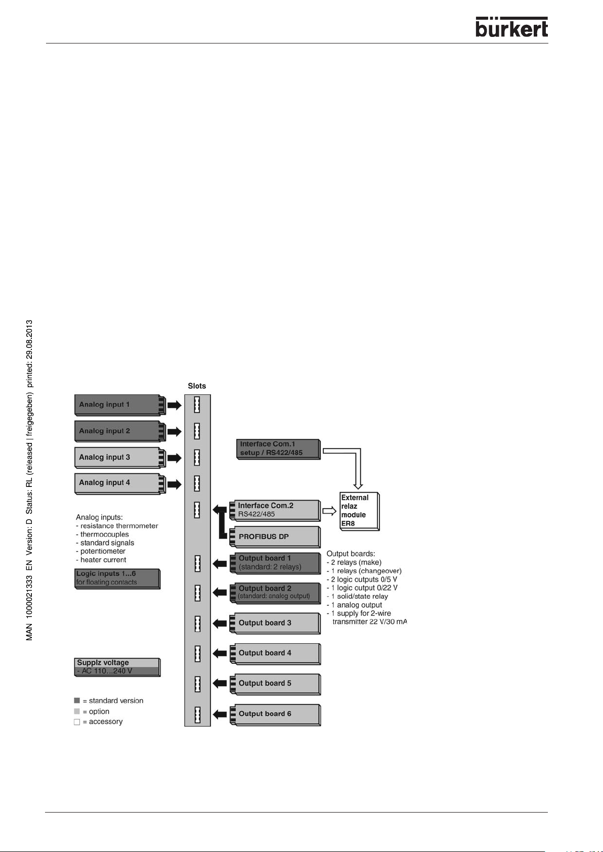
T ype 1150 is a process and progr am controller with up to four controller or program channels. The
instrument is built to the format 144 mm x 130 mm for a standard 92 mm x 92 mm panel cut-out and a
mounting depth of 170 mm.
The display is a 5" color screen with 27 colors. The lay out of the screen templates can be individually
adapted and adjusted. Two freely configurable screen templates make it possible to customiz e the placing
of texts, process values, background pictures and icons.
A maximum of 4 analog inputs and 6 logic inputs are available, as well as six expansion slots for switched
or analog outputs.
A setup program is available for direct configuration via a PC. Linearizations for the usual transmitter
outputs are stored within the instrument, four customer-specific linearization tables can be programmed.
A math and logic module can be used to adapt the instrument to a very wide range of control tasks.
A serial interface RS422/485 or Profibus-DP can be used to integrate the instrument into a data network.
Modules can be retrofitted quite simply by the user.
The electrical connection is made at the back of the instrument, via plug-in screw terminals.
Block structure
10 - 1150
Page 13
Visual Representation
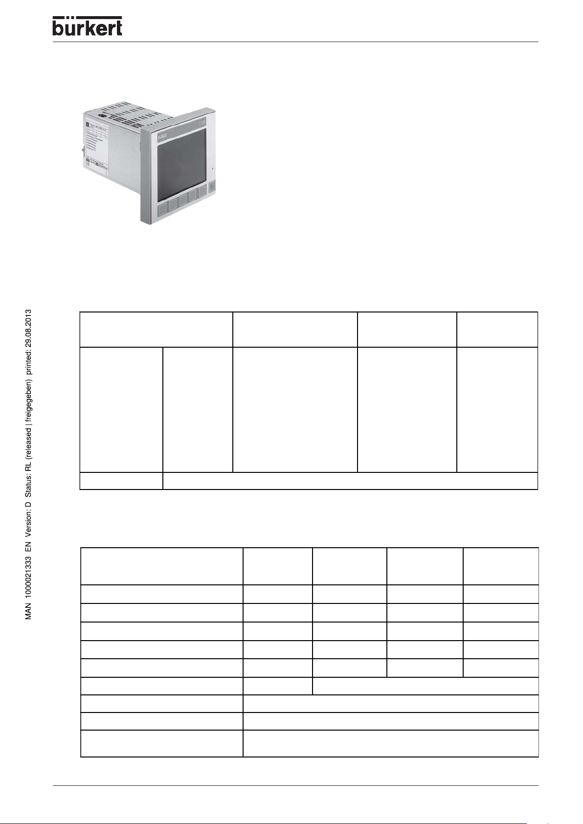
Technical data
Thermocouple input
SYSTEM DESCRIPTION
Designation Measurement range Meas. accuracy
Fe-CuN i "L "
Fe-CuN i "J "
Cu-CuNi "U"
Cu-CuNi "T"
NiCr-Ni "K"
NiCr-CuNi "E"
NiCrSi-NiSi "N"
Pt10Rh-Pt "S"
Pt13Rh-Pt "R"
Pt30Rh-Pt6Rh "B"
W5Re-W26Re "C"
W3Re-W25Re "D"
W3Re-W26Re
Cold junction Pt 100 internal, external or constant
DIN EN 60584
DIN EN 60584
DIN EN 60584
DIN EN 60584
DIN EN 60584
DIN EN 60584
DIN EN 60584
DIN EN 60584
1
With 250 msec sampling time.
-200 to +900°C
-200 to +1200°C
-200 to +600°C
-200 to +400°C
-200 to +1372°C
-200 to +1000°C
-200 to +1300°C
0 to 1768°C
0 to 1768°C
0 to 1820°C
0 to 2320 °C
0 to 2495 °C
0 to 2400 °C
0.25%
0.25%
0.25%
0.25%
0.25%
0.25%
0.25%
0.25%
0.25%
0.25%
0.25%
0.25%
0.25%
Input for resistance thermometer (RTD)
Designation Connection
circuit
Pt100 DIN EN 60751 2-wire/3-wire -200 to +850°C
Measurement
range
Meas. accuracy1Ambient
0.05%
1
Ambient
tempera ture
error
100 ppm/K
100 ppm/K
100 ppm/K
100 ppm/K
100 ppm/K
100 ppm/K
100 ppm/K
100 ppm/K
100 ppm/K
100 ppm/K
100 ppm/K
100 ppm/K
100 ppm/K
temperature
error
50 ppm/K
Pt 50,500, 1000 DIN EN 60751 2-wire/3-wire -200 to +850°C
Cu50 2-wire/3-wire -50 to +200°C
Ni100 DIN 43 760 2-wire/3-wire -60 to +250°C
KTY11-6 2-wire -50 to +150°C
PtK9 2-wire lithium-chloride transducer
Sensor lead resistance max. 30 ohms per lead for 2-wire or 3-wire circuit
Meas. current 250 A
Lead compensation is not required for 3-wire circuit. With a 2-wire circuit, the lead resistance can be
1
With 250 msec sampling time.
compensated in software by a correction of the process value.
0.1%
0.1%
0.05%
1.0%
50 ppm/K
50 ppm/K
50 ppm/K
50 ppm/K
1150 - 11
Page 14
SYSTEM DESCRIPTION
Input for standard signals
Designation Measurement range Meas. accuracy
Voltage 0 to 10 V
Current 4 to 20 mA, voltage drop 1 V
Heater current 0 to 50 mA AC
Potentiometer min. 100 max. 10 k
-10 to +10 V
-1 to +1 V
0 to +1 V
0 to 100 mV
-100 to +100 mV
Input resitance R
0 to 20 mA, voltage drop 1 V
1
With 250 msec sampling time.
100 k
E
0.05 %
0.05 %
0.05 %
0.05 %
0.05 %
0,05 %
0.1 %
0.1 %
1 %
Logic inputs
Floating contacts
Measurement circuit monitoring
In the event of fault, the outputs move to a defined (configurable) status.
1
Ambient
temperature
error
100 ppm/K
100 ppm/K
100 ppm/K
100 ppm/K
100 ppm/K
100 ppm/K
100 ppm/K
100 ppm/K
100 ppm/K
Sensor Overrange /
underrange
Thermocouple
Resistance thermometer
Voltage 2 to 10V
0 to 10V
Current 4 to 20 mA
0 to 20 mA
recognized - not recognized
Outputs
Relay
contact rating
contact life
Logic
current limiting
Solid-state relay
contact rating
protection circuitry
Voltage
output signals
load resistance
Current
output signals
load resistance
Supply voltage for 2-wire
transmitter
voltage
current
0/5 V
20 mA
Probe or lead short-circuit Probe or lead break
-
-
-
-
-
changeover contact or 2 x make
3A at 250 V AC resistive load
150.000 operations at rated load
or 0/22 V
30 mA
1 A at 230 V
varistor
0 to 10 V / 2 to 10 V
500
R
Last
0 to 20 mA / 4 to 20 mA
450
R
Last
22 V
30 mA
12 - 1150
Page 15
Controller
Controller type single-setpoint controller
double-setpoint controller, modulating controller, proport ional controller,
proportional controller with integrated actuator driver
Controller structures P/PD/PI/PID/I
A/D converter dynamic resolution up to 16 Bit
Sampling time 250 msec
50 msec, 150 msec, 250 msec (configurable)
Color screen
Resolution 320 x 240 pixels
Size (screen diagonal) 5" (12.7 cm)
No. of colors 27 colors
Electrical data
SYSTEM DESCRIPTION
Supply voltage (switchmode PSU) AC 48 to 63 Hz, 110 to 240 V -15/+10%
Electrical safety to DIN EN 61 010, Partl 1
Power consumtion max. 30 VA
Data backup flash memory
Electrical connection at rear, via plug-in screw terminals
Electromagnetic compatibility
interference emission
interference immunity
overvoltage category III, pollution degree 2
conductor cross-selection max. 2.5mm
with core ferrules (length: 10mm)
EN 61 326
Class B
to industrial requirements
Interface COM1
Interface type PC-Interface or RS 422/RS 485
Protocol MOD-Bus
Baud rate 9600, 19200, 38400
Device address 1 to 255
Minimum response time 0 to 500 ms
Interface COM2
2
MOD bus
Interface type RS 422/RS 485
protocol MOD-Bus
Baud rate 9600, 19200, 38400
Device address 1 to 255
Profibus DP
Device address 1 to 128
Data transmission rate 12 MBaud
1150 - 13
Page 16
SYSTEM DESCRIPTION
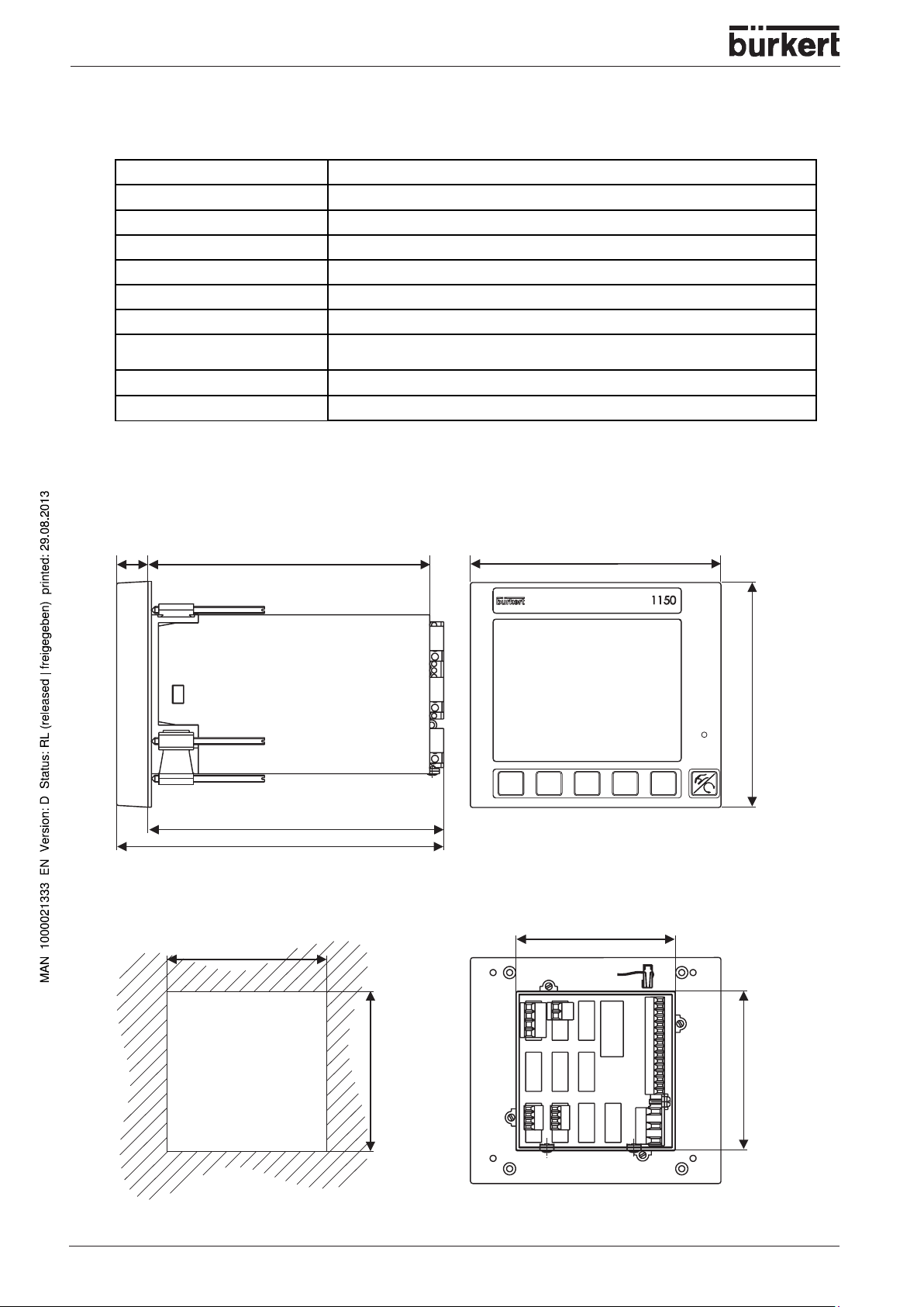
Housing
Housing type housing and back panel: metal for panel mounting as per DIN 43700
Front bezel plastic to UL 94 V0 144 mm x 130 mm
Mounting depth 170 mm
Panel cut-out 92+
Ambient/storage temperature range -5 to 50 °C / -40 to +70 °C
Climatic conditions rel. humidity 75 % annual mean, no condensation
Operating position horizontal
Enclosure protection to EN 60 529,
Weight (fully fitted) approx. 1400 g
Membrane keypad polyester film, resistant to normal washing and cleaning agents
Dimensions
0,8
0,8
x 92+
mm
front IP 65, rear IP 20
18 162
170
188
Panel cut-out
to DIN ISO 43 700
+0,8
92
0
Front viewSide view
144
130
Rear view
91.5
setup plug
14 - 1150
+0,8
0
92
91.5
Page 17
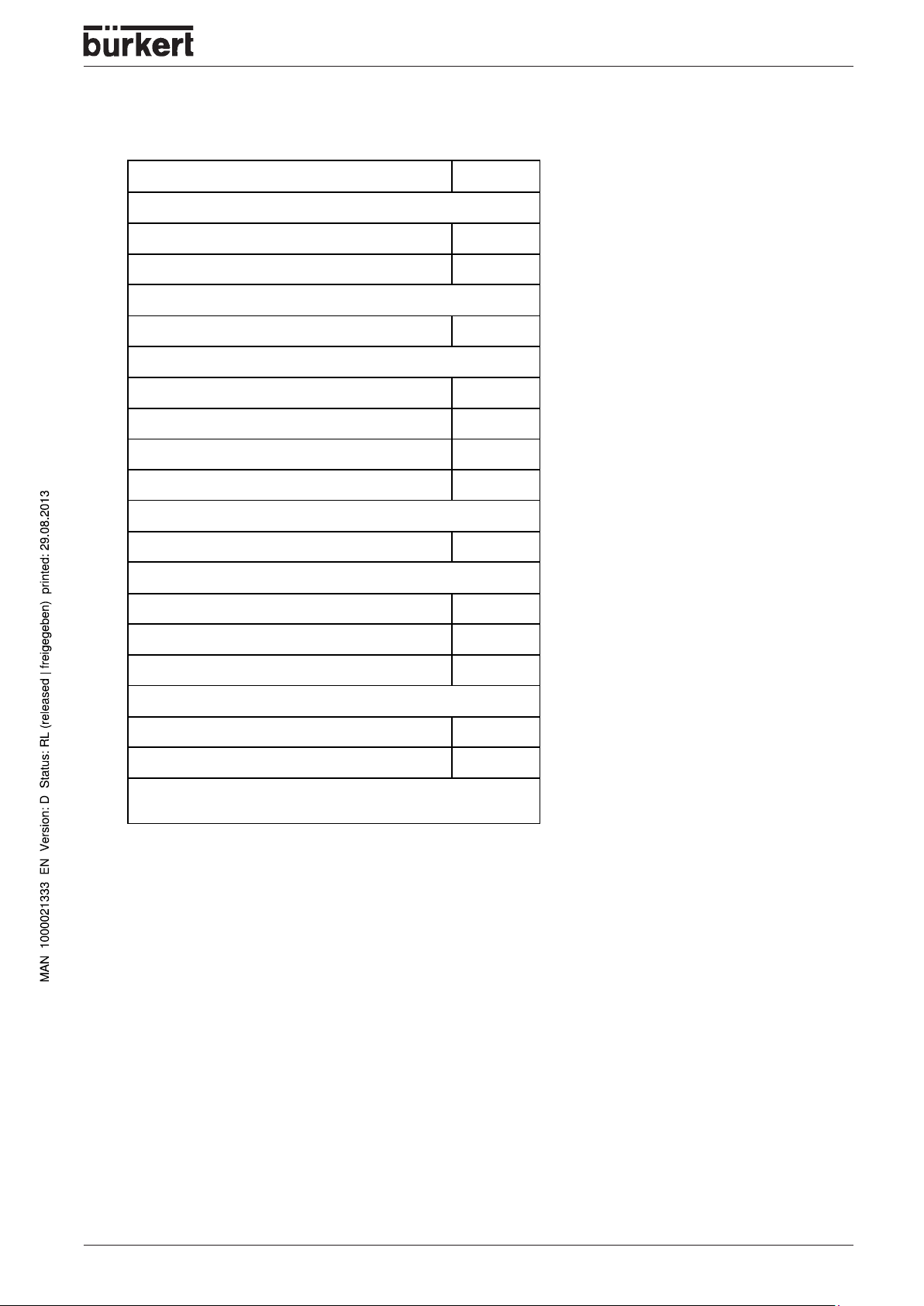
Order table
Process and program controller Type 1150 ID-No.
Basic unit
20 to 30 V AC/DC 787703
110 to 240 V 48 to 63 H z 787704
Input modules
1 analog inpu t 787750
Output modules
1 relay, changeover 787751
1 solid-state relay 787752
2 relay, n.o. 787753
1 analog output 787754
SYSTEM DESCRIPTION
Interface
Profibus DP 787755
Added optional functions *
Controller channels 3+4 787756
Recording fu nctio n 787757
Math and logic module 787758
Accessories
PC-Interface for setup program 787759
Setup software with Program editor 787760
Configuration o f adde d opti onal func tion s is onl y poss ible by mea ns of
*
the Setup-Software PC edi tor.
1150 - 15
Page 18

SYSTEM DESCRIPTION
16 - 1150
Page 19

INSTALLATION, COMMISSIONING AND MAINTENANCE
INSTALLATION,
COMMISSIONING
AND MAINTENANCE
General notes ............................................................................................................................................................................................................................. 18
Location and climatic conditions
Close mounting
Assembly
Installation
Accessories
Maintenance
......................................................................................................................................................................................................................... 18
.......................................................................................................................................................................................................................................... 18
........................................................................................................................................................................................................................................ 19
.................................................................................................................................................................................................................................. 20
.................................................................................................................................................................................................................................. 20
.......................................................................................................................................................................... 18
1150 - 17
Page 20
INSTALLATION, COMMISSIONING AND MAINTENANCE
General notes
ATTENTION!
• This device should only be installed or repaired by qualified personel using the correct
tools!
• Always disconnect the power this device before servicing or changing signal
connections!
• Failure or interf erence may result from contamination, short circuit, voltage interruption
or faulty/missing wiring termination.
• Check for loose or improper electrical connections or under voltage if unit does not
power up.
Location and climatic conditions
• The conditions at the location must meet the requirements specified in the technical data.
• The ambient temperature at the location should be - 5 to + 50 °C with a relative humidity below 75%
Close mounting
• Minimum spacing of panel cut-outs
horizontal min. 54 mm
vertical min. 54 mm
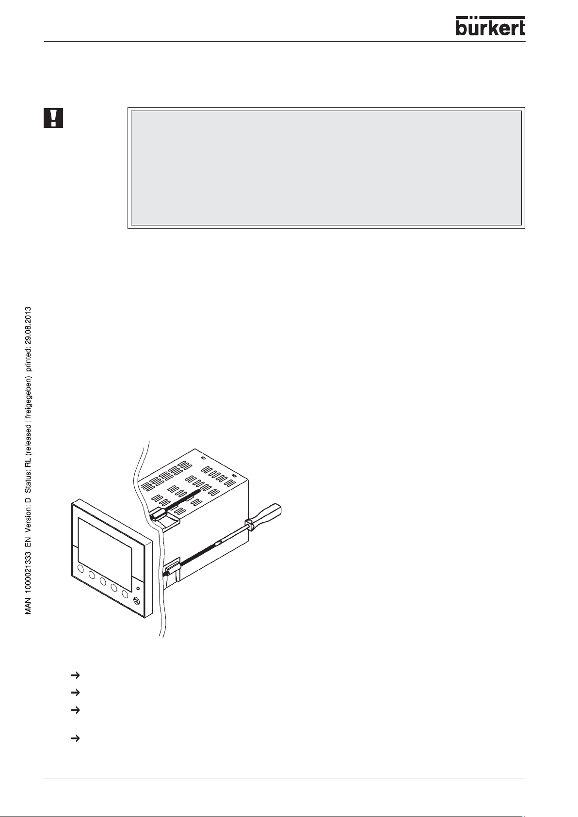
Assembly
From the bac k, fit the seal that is supplied onto the instrument.
Insert the instrument from the front into the panel cut-out.
18 - 1150
From behind the panel, slide the mounting brac kets into the guides on the sides of the housing. The flat
faces of the mounting brackets must lie against the housing.
Push the mounting brackets up to the bac k of the panel, and tighten them e venly with a scre wdriv er .
Page 21

Installation
INSTALLATION, COMMISSIONING AND MAINTENANCE
ATTENTION!
• The choice of cable - the installation and the electrical connection must conform to the requirements of
VDE 0100 “Regulations on the Installation of P ower Circuits with Nominal V oltages below 1000 V” or the
appropriate local regulations.
• The electrical connection may only be carried out by properly qualified personnel.
• The instrument must be disconnected/isolated electrically incase of accidental contact with live parts.
• A current-limiting resistor interrupts the supply circuit in the event of a short-circuit. Ho we v er , the load
must be fused for the maximum relay current to prevent the contacts of the output relay from becoming
welded in the event of a short-circuit.
• Electromagnetic compatibility conforms to the standards and regulations cited in the technical data
(see Chapter Technical data).
• Run input, output and supply cables separately and not parallel to one another .
• All input and output signal cables must be shielded twisted pairs to prevent crosstalk, electrical noise
and interferences.
• The shield of all transmission lines must be connected on the instrument side to potential earth.
• The PE terminal on the instrument must be connected to earth ground. This cab le must ha ve at least
the same conductor cross-section as used for the supply cables. Grounding and earthing leads must be
wired in a star configuration to a common earth point that is connected to the protective earth of the
electrical supply . Do not loop earth or ground connections, i.e . do not run them from one instrument to
another.
Please observe the relevant safety regulations and electrical installation codes for your
area.
• Do not connect any additional loads to the supply terminals of the instrument.
• The instrument is not suitable for use in areas with an explosion hazard (Ex areas).
• In addition to faulty installation, incorrect programming/configuration of the controller (setpoint, data of
the parameter and configuration levels, internal alterations) can also interfere with the correct operation
of dependent processes, or even cause damage. Safety devices should always be provided that are
independent of the controller (such as overpressure valves or temperature monitors/limiters) and only
capable of adjustment by authorized personnel.
• Since adaptation (self-optimization) cannot be expected to handle all possible control loops, an unstable
process parameterization is theoretically possible. The stability of the actual value derived from the selftune should therefore be checked.
• The measurement inputs of the controller must not exceed a maximum potential of 30 V A C or 50 V DC
against PE.
1150 - 19
Page 22
INSTALLATION, COMMISSIONING AND MAINTENANCE
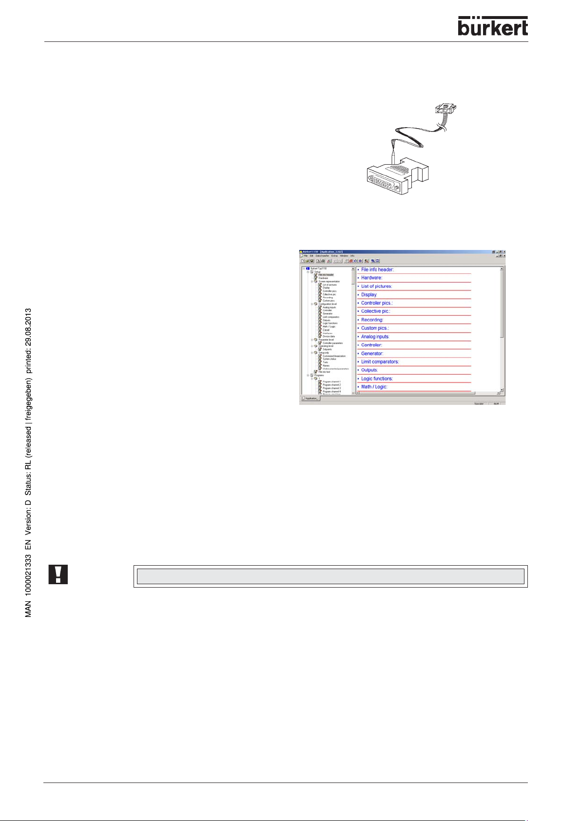
Accessories
PC Interface
PC interface for setup program
Setup programs
Setup program with program editor
Maintenance
Cleaning
The front panel can be cleaned with normal commercial washing, rinsing and cleaning agents. It has a
limited resistance to organic solvents (e.g. methylated spirits, white spirit, P1, xylol etc.). Do not use highpressure cleaning equipment.
Disposal
ATTENTION!
Please refer to local bylaws/regulations for proper disposal of device.
20 - 1150
Page 23

ELECTRICAL CONNECTIONS
ELECTRICAL
CONNECTIONS
Connection diagram............................................................................................................................................................................................................ 22
Terminal strip numerical assignment
............................................................................................................................................................. 22
1150 - 21
Page 24
ELECTRICAL CONNECTIONS
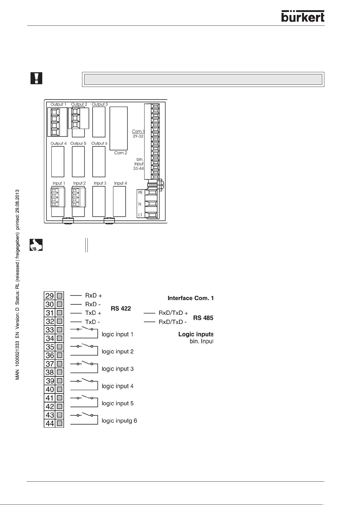
Connection diagram
ATTENTION!
NOTE
The electrical connection must only be carried out by properly qualified personnel.
The instrument version can be identified by means of the type code (See nameplate on
the housing).
Terminal strip numerical assignment
22 - 1150
Page 25
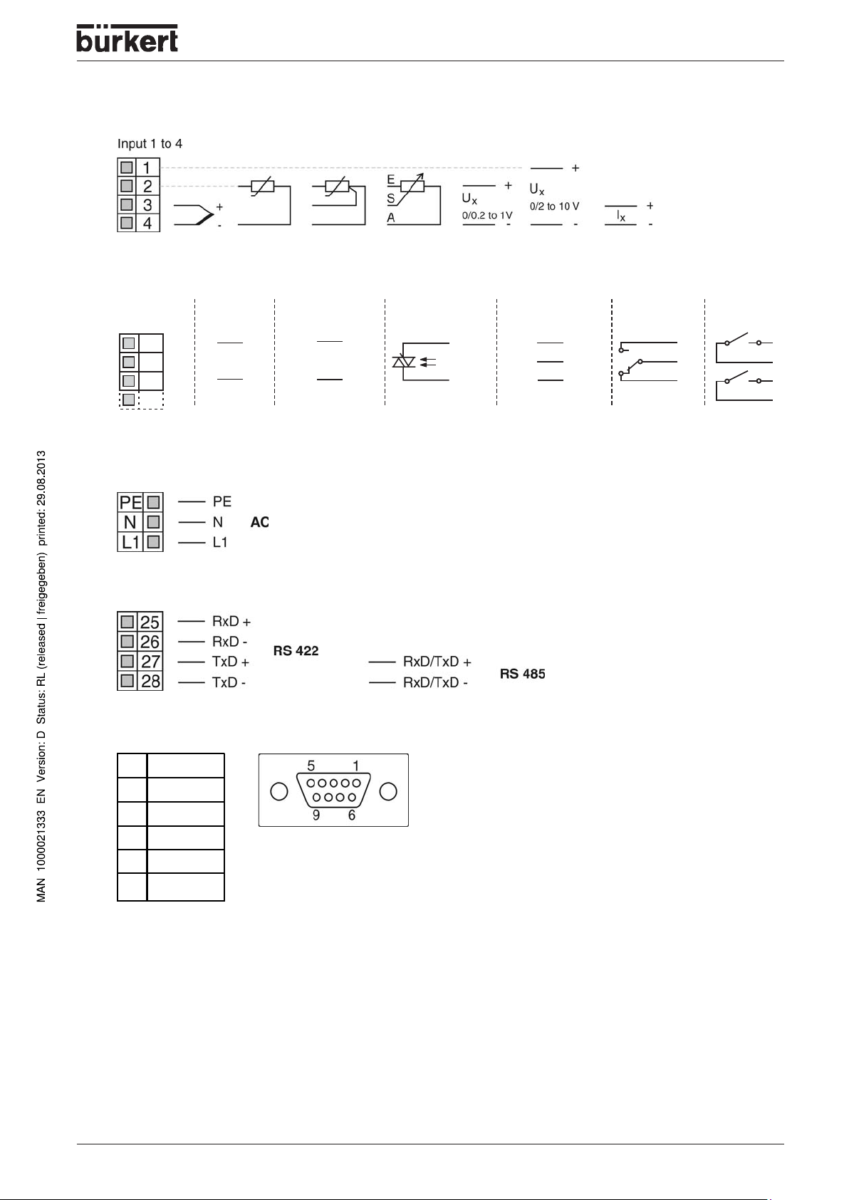
Analog inputs
1 analog
output
1 logic output
0/22 V *
1 solid/state relay
230 V/1 A
2 logic outputs
0/5 V
1 changeover 2 makeOutput
1 to 6
X
X
X
X
5
6
K1
7
8
K2
9
10
11
12
S
Ö
P
13
15
GND
A1
16
17
19
20
GND
A
22
24
-
+
0/2 - 10 V
0/4 - 20 mA
* or supplz for 2-wire transmitter
23
21
18
14A2
Outputs
ELECTRICAL CONNECTIONS
Supply voltage
Interface COM.2
Profibus-DP
Pin Assignment
3 RxD/TxD-P
4RTS
5DGND
6VP
8 RxD/TxD-N
1150 - 23
Page 26

ELECTRICAL CONNECTIONS
24 - 1150
Page 27

OPERATION AND CONTROLLER FUNCTIONS
OPERATION AND
CONTROLLER FUNCTIONS
Operation.............................................................................................................................................................................................................................................. 26
Displays and controls.......................................................................................................................................................................................................... 26
Overview of operation ......................................................................................................................................................................................................... 28
Entering values and selecting settings.............................................................................................................................................................. 31
Setpoint input .............................................................................................................................................................................................................................. 32
Recording ........................................................................................................................................................................................................................................ 33
Operation “Controller“ ....................................................................................................................................................................................................... 34
Setpoint ............................................................................................................................................................................................................................................. 34
Manual mode ............................................................................................................................................................................................................................... 34
Operating „program controller/generator“................................................................................................................................................ 36
Program editor............................................................................................................................................................................................................................ 36
Starting the program............................................................................................................................................................................................................. 39
Overview of operation ......................................................................................................................................................................................................... 40
Shifting the program profile ........................................................................................................................................................................................... 41
1150 - 25
Page 28
OPERATION AND CONTROLLER FUNCTIONS
Operation
Displays and controls
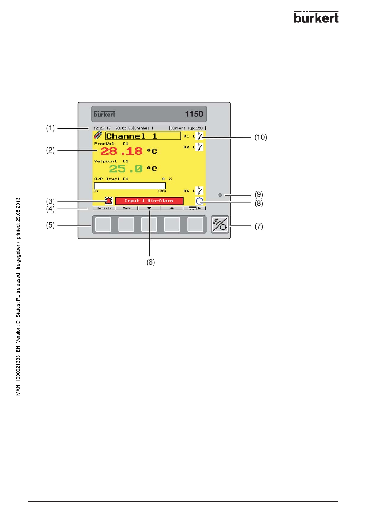
Front view
Displays and controls
(1)
Status line
with time, date, name of screen template and instrument name
(2)
Color screen (screen templates can be configured)
Factory setting for fix ed-setpoint controller: process value, setpoint, output (bar graph)
Factory setting for program controller: process value, setpoint, program number/name,
segment number, remaining programm time
(3)
Info/alarm symbol
(4)
Title
Current meaning of the softkeys
(5)
Keys
(Softkeys) with various interpretations in the colot screen
(6)
Info/alarm symbol
Display of infos (blue) or alarms (red)
(7)
EXIT/manual key
for manual mode, navigation, and for aprogram pause
(8)
Operating mode/state
(9)
Po wer LED
lights up green when voltage is applied
(10)
26 - 1150
Status indicators of the outputs (configurable)
Page 29
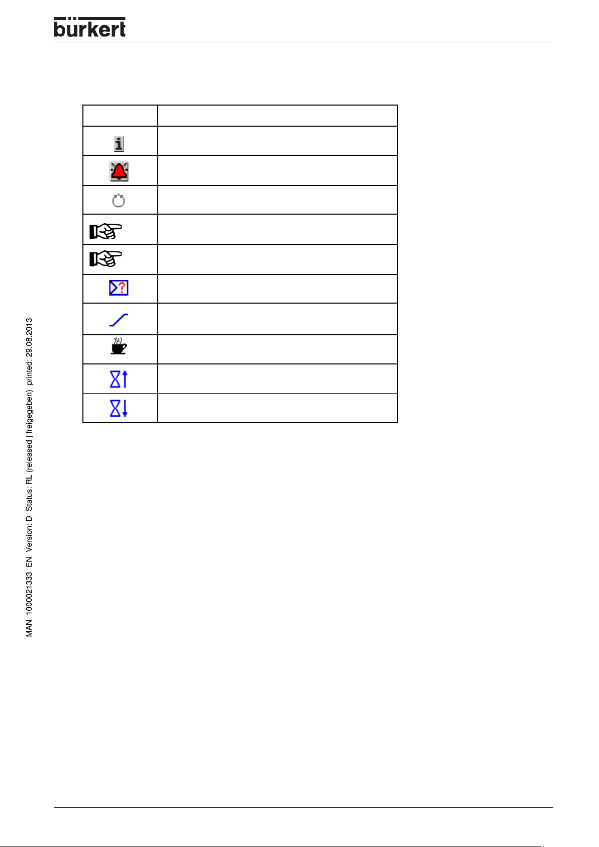
Symbols in display
Symbol Meaning
Info
Alarm is present
Automatic mode/Program is ru nning
OPERATION AND CONTROLLER FUNCTIONS
(blue)
(green)
Manual mode /"Manua l" operating m ode
Controller manual mode
Self-optimization is a ctive (symbol flash es)
Ramp function is active
Program pause
Actuator open (modulating controller)
Actuator closed (modulating controller)
1150 - 27
Page 30
OPERATION AND CONTROLLER FUNCTIONS
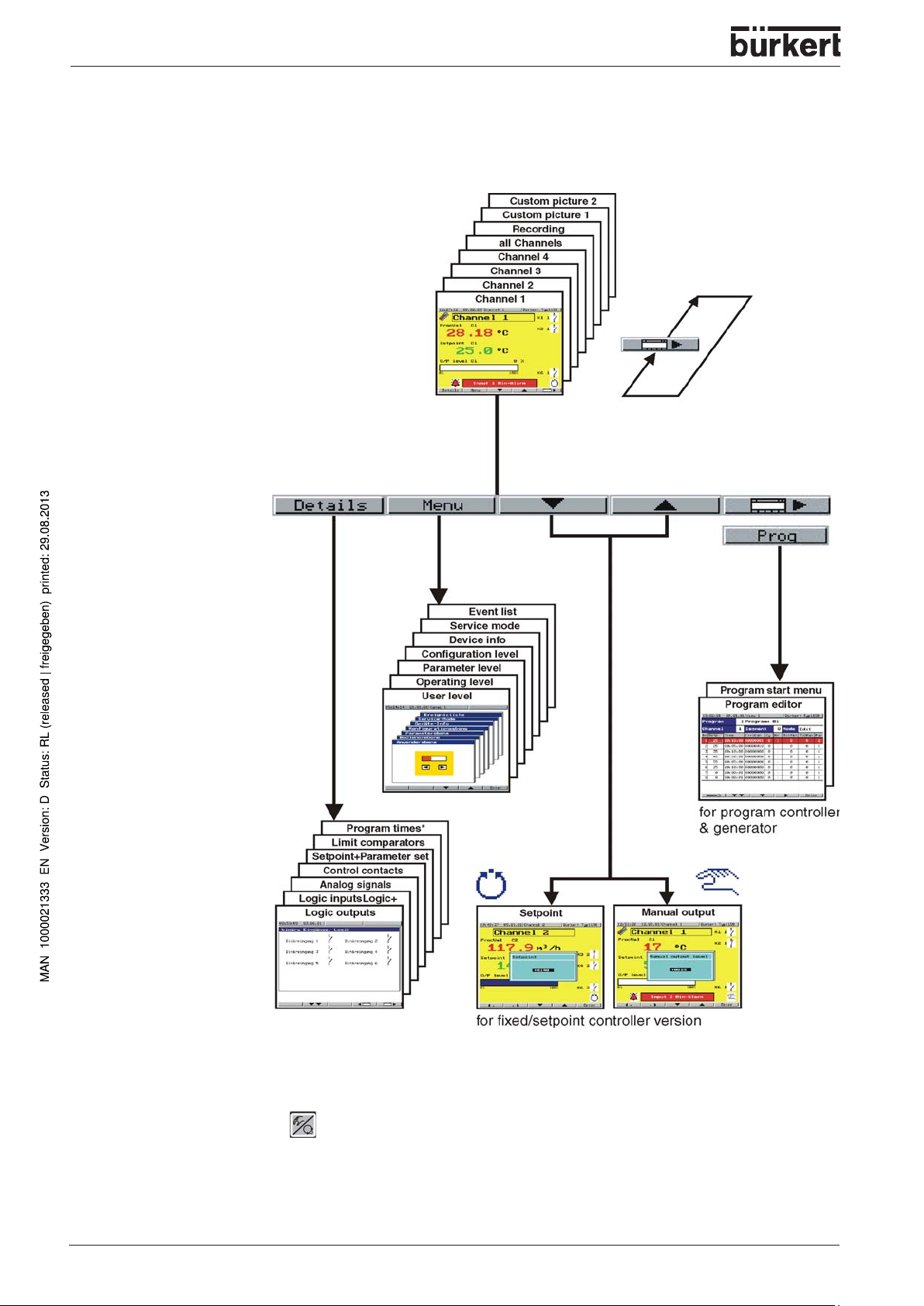
Overview of operation
Screen operating loop
Menu
Program
start menu
Details
see Chapter
Configuration/Display
Setpoint/
Manual output
28 - 1150
(> 2 s) = back to the screen operating loop
Time Out = If no key is pressed the display will automatically return to the
screen operating loop after a definable time.
Page 31

OPERATION AND CONTROLLER FUNCTIONS
Screen operating loop
The operating loop contains the screen templates for a maximum of four controller channels, the collective
picture of all the active controller channels, the recording function as well as two freely definable screen
templates. The screen templates can be individually switched into display.
(see Chapter Configuration/Display)
Meaning of the keys
:
- additional functions of the softkeys
- start/cancel self-optimization for the channel that is displayed
- acknowledge alarm messages and limit comparators
- step on one segment (program controller)
- controller manual mode (program controller)
Details
The states and values of the various process variab les are presented in a clear and structered manner .
* Screens only available for process controllers
- scroll screen down
1150 - 29
Page 32

OPERATION AND CONTROLLER FUNCTIONS
Menu
•
User level
With the help of this screen template, the user can compile parameters that have to be frequently
altered, through the setup program. This screen template is only displa yed when appropriately
configured.
•
Operating level
Here the setpoints for all four controller channels are defined and self optimization is started
(see Chapter
•
Parameter level
The controller parameters for the controller channels are defined here (see Chapter
•
Configuration level
The instrument is adapted to the control task here (see Chapter
•
Device info
Information on hardware equipment, software version and instrument options are shown here.
•
Service mode
This screen template can only be accessed by service personnel.
•
Event list
Different events (e.g. alarm messages, limit comparator signals) are documented here.
“Self-optimization“
).
“Parameterization“
“Configuration“
).
).
30 - 1150
Page 33

OPERATION AND CONTROLLER FUNCTIONS
Entering values and selecting settings
Entering values
Parameters can be altered in a number of screen templates:
Select parameters
Increase parameter value with
Decrease parameter value with
The longer the key is pressed the f aster the v alue changes . Approx. 2 sec after releasing the key, the
entry will be automatically accepted.
Parameters can be altered within their range of v alues or within the maximum displa yab le values (e . g. tw o
decimal places: -99.99 to +99.99).
Shifting the decimal point
Increase decimal place with
Decrease decimal place with
Selecting
Select parameter
Move up in selection list with
Move down in selection list with
Confirm entry with
Entering codes and times
Times and codes are entered digit by digit.
Increase or decrease value (digit) with and
On to the next digit with or
Confirm entry with
1150 - 31
Page 34

OPERATION AND CONTROLLER FUNCTIONS
Setpoint input
Configuration in controller
Each controller channel has four setpoints and the provisions to switch between them. Setpoints for the
controller are defined as shown below:
(see Chapter “
Controller and Logic functions“
)
32 - 1150
Page 35

OPERATION AND CONTROLLER FUNCTIONS
Recording
Screen template
The recording function can be used to show the traces of up to four analog signals and the switching
actions of up to three logic signals.
Momentary values of up
to four analog signals
Graphical representation
of the analog signals
Scaling of the analog
signals (switchable)
Time axis
(format hh:mm:ss)
Graphical representation
of the logic signals
Time grid
Keys
- call up history
- switch display for the analog signal scalings
History
Data that have already been recorded can be vie wed here. The recorded time span is shown on the time
axis. The recorded time span depends on the sampling rate (adjustab le) and varies between 12 hours and
a maximum of 1 day.
Shift the trace with , , ,
Call up zoom function with (key field is switched)
Zoom in /zoom out of trace with or
Return to the scroll functions with
Quit history with
1150 - 33
Page 36

OPERATION AND CONTROLLER FUNCTIONS
Operation “Controller“
If the instrument has been configured as a fixed-setpoint controller , the following actions can be perf ormed
in automatic/manual mode:
Altering the setpoint
The active setpoint of a controller channel can be altered in the corresponding screen template. The
controller must be in automatic mode.
Alter setpoint using and
(the meaning of the softkeys changes, an input window appears)
automatic mode
Shift the decimal point using and
New setpoint is automatically accepted after 2 sec or by using
Manual mode
Altering the output
The control loop of the controller channel that is displayed can be interrupted by switching to manual
mode.
Switch to manual mode with (hold key down for at least 2 sec!)
(the symbol for manual mode appears in the operating mode display)
Alter the output with and
(the meaning of the softkeys changes, an input window appears)
34 - 1150
manual mode
Shift the decimal point using and
The new output is automatically accepted after about 2 sec or by using
Page 37

OPERATION AND CONTROLLER FUNCTIONS
Altering the output for modulating controllers
In the case of modulating controllers, the keys are used to directly influence the right and left motion of a
motorized actuator. The output is only indicated if the output f eedback is connected.
- open actuator
- close actuator
The manual mode can be inhibited.
1150 - 35
Page 38

OPERATION AND CONTROLLER FUNCTIONS
Operating „program controller/generator“
If the instrument is configured as a program controller/generator, progr ams hav e to be created first, by
using the internal program editor or the setup program.
Program editor
General
50 programs with up to 99 segments can be programmed; a total of 1000 segments can be implemented.
Programs are created by programming setpoints and segment times, segment by segment.
Furthermore, the states of the control contacts 1 — 8 and the active parameter set can be defined for
each segment.
The setpoint profiles can be output either as a ramp or a step (configurable).
Output as a ramp has been chosen for the following diagrams.
Tolerance band
To monitor the process value, a tolerance band can be applied around the setpoint profile f or each
segment.
If the upper or lower limit is infringed, a tolerance band signal is generated, which is internally processed
or produced via an output.
(see Chapter
36 - 1150
“Outputs and Logic functions“
)
Page 39

Program editor
OPERATION AND CONTROLLER FUNCTIONS
Call up with
Select program using the cursor keys
Select program channel using the cursor keys
Number of program channel
edit program
Program number and name
Number of program
segments
Entry mode
- edit
- temporary alteration
Segment setpoint
Segment number
- call up additional softkey functions
Parameter set number
Lower and upper tolerance band
Number of repeat cycles (Cy) with
start segment (No.)
Control contacts 8 — 1 (1=On)
Segment time
1150 - 37
Page 40

OPERATION AND CONTROLLER FUNCTIONS
Entering a new program
The segments are edited in sequence when creating a new program.
Append a new segment to the last segment of the profile trace with
Copying segments
Existing segments can be copied and inserted in another position in the program. The segment that was
copied is inserted above the cursor position.
Position the cursor on the segment to be copied
Copy segment with
Position the cursor on the desired position
Insert segment with
Inserting segments
A new segment can be inserted above the cursor position into an existing sequence of segments .
Insert segment with
Removing segments
Delete marked segment with
Entering repeat cycles
A group of segments that are arranged in sequence can be repeated up to 99 times or repeated endlessly
(input: -1). The repeat cycles are progr ammed in the last segment of the group .
Example: S02 - S04 are to be repeated once.
Edit segment 4
Set number of repeat cycles to Cy=1
Set start segment of repeat to No.=2
Checking the program profile
The program segments entered in the table can be graphically displayed and checked. Repeat cycles are
not taken into account for the display.
Show program profile with
38 - 1150
Page 41

OPERATION AND CONTROLLER FUNCTIONS
Starting the program
Immediate start of program
The program displayed on the screen in the basic status is started.
Start program with
A program can also be selected, started and canceled via the logic functions. The logic function “Progr am
selection” has priority over the settings in the menu “Program start”.
(see Chapter “Logic functions“)
Selecting and starting the program
The representation of the program selection can be configured as a list or an icon.
(see Chapter
“Device data”
)
Call up program selection with
Select program using the cursor keys
Start program with 2x the program starts immediately at the start
start program
Starting the program with time input
A program can be started at a specific point of time. There are two configurable options:
1. Start at a specified date and time
2. Start with a specified start delay in hours, minutes and seconds.
(see Chapter
NOTE
Call up program selection with
Select program using the cursor keys
Change to menu “Program start” with
“Generator”)
The settings are reset to their standard values after the start of the program.
start program
Enter start time/start date or start delay, start segment and remaining segment time
Start program with
1150 - 39
Page 42

OPERATION AND CONTROLLER FUNCTIONS
Overview of operation
The diagram below provides an overview of the different operating modes and operating options of a program controller .
Many operating options can also be implemented via the logic functions.
Buttons and can be accessed via “Details”.
Basic status
In basic status the system state is defined, with the following factory settings for all program channels:
controller, control contacts and limit comparators are inactiv e
the controller setpoints are 0
parameter set 1 is active for all controllers
The system state can be modified via the setup program.
Temporary alterations
T emporary alterations are modifications to the current program in the program editor . They are not stored in
the program memory, i.e. modifications will be lost after a restart.
In the case of alterations concerning the current segment, the setpoint sequence is automatically adapted.
40 - 1150
Page 43

OPERATION AND CONTROLLER FUNCTIONS
Shifting the program profile
The function “External setpoint with correction” can be used to shift the program profile upwards or
downwards.
The external setpoint is defined via an analog signal (see Chapter “Controller”).
1150 - 41
Page 44

OPERATION AND CONTROLLER FUNCTIONS
42 - 1150
Page 45

PARAMETERIZATION
PARAMETERIZATION
1150 - 43
Page 46

PARAMETERIZATION
Parameter sets
General
Two parameters sets can be stored f or each controller channel.
Access code
Factory-set code:
0001
The access code can be modified via the setup program.
Parameter level / Controller 1 (2...4) / Parameter set 1 (2)
Parameter Value range Factory setting Meaning
Controller structure 1 P, I, PD, PI, PID PID Only PI and PID can be implemented on modulating
Proportional band 0 - 9999 Digit 0 Digit Size of the proportional band
Derivative time 0 - 9999 sec 80 sec Determines the derivative component of the controller output
Reset time 0 - 9999 sec 350 sec Determines the integral component of the contoller output
Cycle time 0 - 9999 sec 20 sec When using a switched output, the cycle time should be
Contact spacing 0 - 999 Digit 0 Digit The spacing between the two control contacts for 2-setpoints
controllers.
Proportional band = 0 means that the controller structure is
ineffective! (limit comparator response)
In the case of proportional controllers, the proportional band
must be > 0.
signal.
signal.
chosen so that a) the pulsed energy flow to the process does
not cause any intermissible fluctuations of the process value
and b) the switching elements are not overloaded.
or modulating controllers, or proportional controllers with an
integrated actuator driver.
Switching differential 0 - 999 Digit 1 Digit Hysteresis for switching controllers with proportional band = 0
Actuator time 5 ... 3000 sec 60 sec T he actually utilized operating time of the regulating valve for
Working point - 100 ... + 100 % 0 % Output level for P and PD controllers
Output level limiting 0 ... 100 % 100 % The maximum limit for the output level.
- 100 ... + 100 % - 100 % The minimum limit for the output level.
Minimum relay ON
time
0 ... 60 sec 0 sec Limits the frequency of switching for switched outputs.
modulating controllers or proportional controllers with an
integrated actuator driver.
(when x = then y = Y0)
44 - 1150
Page 47

Controller structure 2 / ...
PARAMETERIZATION
Controller structure 2 P, I, PD, PI,
Proportional band 0 - 9999 Digit 0 Dig it
Derivative time 0 - 9999 s 80 sec
Reset time 0 - 9999 s 350 sec
Cycle time 0 - 9999 s 20 sec
Switching differential 0 - 999 Digi t 1 Digit
Minimum rel ay ON ti me 0 - 60 s 0 sec
NOTE
The parameter display on the instrument depends on the controller type selected.
(see Chapter
PID
“Controller“
PID The parameters refer to the second controller outp ut for 2-setpoint
)
and modulating controllers.
1150 - 45
Page 48

PARAMETERIZATION
46 - 1150
Page 49

CONFIGURATION
CONFIGURATION
Parameters and functions at the configuration level.................................................................................................................. 48
Analog inputs
Controller
Generator
Limit comparators
Outputs
Logic functions
............................................................................................................................................................................................................................... 51
........................................................................................................................................................................................................................................... 56
.......................................................................................................................................................................................................................................... 60
................................................................................................................................................................................................................... 64
................................................................................................................................................................................................................................................ 67
........................................................................................................................................................................................................................... 69
Math and logic module
C-level control
Display
................................................................................................................................................................................................................................................. 78
Interfaces
Device data
............................................................................................................................................................................................................................. 76
.......................................................................................................................................................................................................................................... 81
.................................................................................................................................................................................................................................... 82
..................................................................................................................................................................................................... 74
Recording
......................................................................................................................................................................................................................................... 83
1150 - 47
Page 50

CONFIGURATION
Parameters and functions at the configuration level
General
The following applies to the representation of parameters and functions at the configuration level:
The parameter is not displayed or cannot be selected if
• the instrument features do not permit the function assigned to the parameter .
Example:
Output 3 cannot be configured if no output 3 is available in the instrument.
• the parameter is irrelevant to the function that has been configured.
Example:
Analog input 1 is configured to “Pt100”, which means that displa y start and end for standard signals
cannot be selected.
NOTE
Some parameters are only available for a fixed-setpoint controller (with or without ramp
function) or a program controller/generator . For fixedsetpoint controllers , these parameters
and settings are marked by a superscript “F” (e.g. rampF), for program controllers /generators
by a “P”.
Access code
Factory-set code: 0002
Selectors
Selectors are menus which fold down when an individual parameter is selected.
Two standard selectors are defined for the configur ation tables below , f or reasons of clarity:
E.G. Analog selector
Switched off
Analog Imp. 1
...
Analog Imp. 4
Math 1
...
Math 8
Process value C1
Setpoint C1
Ramp end C1
Contro l d ev. C1
Output C1
Process value C2
Setpoint C2
Ramp end C2
Contro l d ev. C2
Output C2
Process value C3
Setpoint C3
Ramp end C3
Contro l d ev. C3
Output C3
Switched off
Measurement of analog input 1
...
Measurement of analog input 4
Result of math formula 1
...
Result of math formula 8
Process value for controller 1
Setpoint for controller 1
Ramp end value for controller 1
Control deviation for controller 1
Output for controller 1
Process value for controller 2
Setpoint for controller 2
Ramp end value for controller 2
Control deviation for controller 2
Output for controller 2
Process value for controller 3
Setpoint for controller 3
Ramp end value for controller 3
Control deviation for controller 3
Output for controller 3
48 - 1150
Page 51

CONFIGURATION
Process value C4
Setpoint C4
Ramp end C4
Control dev. C4
Output C4
Y cascade C1
...
Y cascade C4
Setpoint 1 C1
...
Setpoint 4 C1
Setpoint 1 C2
...
Setpoint 4 C2
Setpoint 1 C3
...
Setpoint 4 C3
Setpoint 1 C4
...
Setpoint 4 C4
Setpoint 1 PCh1
...
Setpoint 1 PCh4
Setpoint 2 PCh1
...
Setpoint2 PCh4
P
P
P
P
Seg. end val. PCh1
...
Seg. end val. PCh4
Output 1 C1
Output 2 C1
Output 1 C2
Output 2 C2
Output 1 C3
Output 2 C3
Output 1 C4
Output 2 C4
RemSegT PCh1
...
RemSegT PCh4
Seg. Time PCh1
...
Seg. Time PCh4
Program time
RemProgT
P
P
P
P
P
P
Analog value
Internal Pt100
Sampling ti me
Process value for controller 4
Setpoint for controller 4
Ramp end value for controller 4
Control deviation for controller 4
Output for controller 4
Standardized output with cascade control for controller 1
...
Standardized output with cascade control for controller 4
Setpoint 1 for controller 1
...
Setpoint 4 for controller 1
Setpoint 1 for controller 2
...
Setpoint 4 for controller 2
Setpoint 1 for controller 3
...
Setpoint 4 for controller 3
Setpoint 1 for controller 4
...
Setpoint 4 for controller 4
Setpoint 1 for program channel 1
...
Setpoint 1 for program channel 4
Setpoint 2 for program channel 1
...
P
P
Setpoint 2 for program channel 4
Current final segment value for program channel1
...
Current final segment value for program channel 4
Controller output 1 for controller 1
Controller output 2 for controller 1
Controller output 1 for controller 2
Controller output 2 for controller 2
Controller output 1 for controller 3
Controller output 2 for controller 3
Controller output 1 for controller 4
Controller output 2 for controller 4
Remaining segment time for progam channel 1 (in seconds)
...
Remaining segment time for progam channel 4 (in seconds)
Segment time for program channel 1 (in seconds)
...
Segment time for program channel 4 (in seconds)
Total program time (in seconds)
Remaining run time of program (in seconds)
any analog value (from adress)
Temperature measurement of internal Pt100
Sampling time of instrument
1150 - 49
Page 52

CONFIGURATION
E.G. Binary selectors
Switched off
Output 1 C1
Output 2 C1
Output 1 C2
Output 2 C2
Output 1 C3
Output 2 C3
Output 1 C4
Output 2 C4
Limit comp. 1
...
Limit comp. 16
Contr. contact 1
...
Contr. contact 8
Logic input 1
...
Logic input 6
Logic 1
...
Logic 8
Binary logic value
Program end
Ramp end 1
...
Ramp end 4
Tolerance band
Manual mode C
...
Manual mode C
Transmitter
Logic OFF
Logic ON
P
F
F
P
Switched off
Controller output 1 for Controller 1
Controller output 2 for Controller 1
Controller output 1 for Controller 2
Controller output 2 for Controller 2
Controller output 1 for Controller 3
Controller output 2 for Controller 3
Controller output 1 for Controller 4
Controller output 2 for Controller 4
Controller output 1
...
P
P
1
4
Limit comparator 16
Control contact 1
...
Control contact 8
Logic input 1
...
Logic input 6
Result of logic linkage 1
...
Result of logic linkage 8
any binary logic value (from address)
Program end signal
Ramp end signal for controller 1
...
Ramp end signal for controller 4
Signal on going above/below tolerance band
Controller 1 in manual mode / program pause
...
Controller 4 in manual mode / program pause
Signal always active
Logic 0
Logic 1
Definition of program times
Different times are defined for the prog ram controller/generator , which can be internally processed and
displayed.
(1) Program time
(2) Remaining program time
(3) Segment time
(4) Remaining segment time
50 - 1150
Page 53

Analog inputs
CONFIGURATION
Configuration
Analog inputs
Controller
Generator
Limit comparators
Outputs
Logic functions
Math / Logic
C-level
Display
Interfaces
Device data
Recording
Depending on the instrument version, up to four analog inputs are a vailable. The
analog inputs are numbered in sequence (input 1 — 4) according to their slot
assignment.
Analog input 1 (2 to 4) / ...
Value / selection Description
Probe
No function No function
RTD 3 - wire
RTD 2-wire Resistance thermometer in 2-wire circuit
RTD 4-wire Resistance thermometer in 4-wire circuit
T/C int. Thermocouple (internal cold junction)
T/C ext. Thermocouple (external cold junction)
T/C const. Thermo couple (constant cold junction)
Pot Potentiometer
Heater current Heater current 0 to 50 mA AC
0 to 20 mA 0 to 20 mA
0 to 10 V 0 to 10 V
0 to 1 V 0 to 1 V
0 to 100 mV 0 to 100 mV
- 10 to + 10 V - 10 V to + 10 V
- 1 to + 1 V - 1 to + 1 V
- 100 to + 100 mV - 100 to + 100 mV
4 to 20 mA 4 to 20 mA
2 to 10 V 2 to 10 V
0,2 to 1 V 0,2 to 1 V
20 to 100 mV 20 to 100 mV
- 6 to 10 V - 6 to 10 V
- 0,6 to 1 V - 0, 6 to 1 V
- 60 to + 100 mV - 60 to + 100 mV
Resistance thermometer in 3-wire circuit
Factory-set on analog input 2 to 4: No function
1150 - 51
Page 54

CONFIGURATION
Analog input 1 (2 to 4) / ...
Value / selection Description
Linearization
Linear
Pt100
Pt100 JIS
Ni100
Pt500
Pt1000
Ni1000
Pt50
CU50
Pt K9
KTY11-6
Fe-CuNi J
NiCr-CuNi E
NiCr-Ni K
NiCrSi-NiSi N
Cu-CuNi T
Pt30Rh-Pt6Rh B
Pt13Rh-Pt R
Pt10Rh-Pt S
Cu-CuNi U
Fe-CuNi L
W5Re_W26Re C
W3Re_W25Re D
W3Re_W26Re
C-level
Customized 1
Customized 2
Customized 3
Customized 4
For customized linearizaton (e.g. „customized 1“) a maximum of 20 knee-points can
be implemented, or a 5th order polynominal functi on programmed (only with setup
program).
„C-level“ linearization is used for the C-level control with a zircon dioxide sensor.
For the linearization „KTY11-6“, the resistance is 2 k at 25 °C. The resistance
value can be adapted via the parameter „KTY: at 25°C / 77°F.
Offset
- 1999 to 0 to + 9999 The offset is used to correct a measured value by certain amount upwards or
NOTE
The controller uses the corrected value (l.e. displayed value) f or its computation. This value
downwards.
Example:
Measured Displayed
value Offset value
294,7 + 0,3 295,0
295,3 - 0,3 295,0
does not correspond to the actual measured value.
If incorrectly applied, this can result in impermissible values of the control variable.
52 - 1150
Page 55

Analog input 1 (2 to 4) / ...
Value / selection Description
Range
CONFIGURATION
Start
to + 9999
- 1999
End
- 1999 to + 9999
The instrumen t will chang e over earli er to the res ponse de fined for
overrange / underrange if the range is restri cted.
Example:
Pt100 (Range: - 200 to + 8 50 ° C). An alarm message is to be generated
for temperatures outside the range 15 to 200 °C.
Range start: 15
Range end: 200
Display
Start
- 1999 to 0
End
- 1999 to 100
to + 9999
to + 9999
On transducers with standard si gnal an d on po tentiome ters, a display
value is assigned to the physical signal .
Example: 0 to 20 mA = 0 to 1500 °C.
The range of the physical signal ca n be 20 % wider or narr ower without
generating an out-of-range si gnal.
Filter
0 to 0,6 to 100 s To adjust the digital input filter (0 s = filter off). 63 % of the alternations
are accounted for after 2x filter time cons tant at a sign al step ch ange.
When the filter time constant is large:
- high damping of distur bance si gnal s
- slow reaction of the process value displ ay to process value chang es
- low limit-frequency (2nd ord er low-pass fi lter)
TK constant val ue
0 to 50 to 100 Temperature of the external cold-junction thermostat.
TK external
Analog input 1
Analog input 2
Analog input 3
Analog input 4
Measurement of the c ol d-ju nction temperature with an temperature
probe.
Heater current monitoring (output)
No function.
Output 1
...
Output 12
The heater current is evaluated using a curren t transforme r with a
standard signal output, wh ich can be monito red by linkin g the anal og
input with a limit comparator.
The measurement is always made when the he ating co ntact is c losed .
The measurement is retaine d until the next measureme nt.
Correction value KTY
0 to 400
1 k * Correction value
1150 - 53
Page 56

CONFIGURATION
Analog input 1 (2 to 4) / ...
Value / selection Description
Recalibration
Start
- 1999 to 0
End
- 1999 to 1
to + 9999
to + 9999
(See below for explanation)
NOTE
As opposed to all the other settings, entry of the start and end value is linked to the latest
measurement at the input concerned.
As a rule, these values cannot be adopted by another instrument.
Customized recalibration
A signal is processed electronically (conversion, linearization …) to produce a measured value via the
analog inputs of the controller. This measured v alue enters into the computations of the controller and can
be visualized on the displays (measured value = displayed value).
This fixed relationship can be modified if required, i.e. the position and the slope of the measurement
characteristic can be altered.
Procedure
Apply two measurement points ((1), (3)), one after another , to the controller; they should be as f ar apart as
possible.
At these measurement points, enter the required display v alue (start value, end value) in the controller. A
reference instrument is most convenient for determining the measured values M1 and M2.
Measurement conditions must remain stable during programming.
54 - 1150
Page 57

CONFIGURATION
Programming
(1) Move to measurement point
(2) Enter start value
(3) Move to measurement point
(4) Enter end value E
1)
If start value=0 or end value=1 is to be set, then the value must first be altered using or
to enable correction.
1)
1)
NOTE
If recalibration is carried out without a reference instrument, the offset must be taken into
account when moving to measurement point (3).
To cancel recalibration, the start and end values have to be prog rammed to the same v alue. This
automatically sets the start value to 0 and the end value to 1.
Any subsequent recalibration will otherwise be based on the corrected characteristic.
1150 - 55
Page 58

CONFIGURATION
Controller
Configuration
Analog inputs
Controller
Generator
Limit comperators
Outputs
Logic functions
Math / Logic
C-level
Display
Inter faces
Device data
Recording
The following are set here: controller type, input v ariables of the controller , the
setpoint limits, conditions for manual mode and the presettings for selfoptimization
of the four controller channels.
Controller 1 (2 to 4) / Configuration
Value / selection Description
Controller type
2 point process controller
3 point process controller
3 point step
Position control
Continuous
2 point process controller
3 point process controller
3 point step automatic controller
Continuous automatic controller with integrated position control
Continuous automatic controller
Control action
Direct
Inverse
Direct:
The controller output Y is > 0 when the process value is smaller than the setpoint
(e.g. cooling).
Inverse:
The controller output Y is > 0 when the process value is larger than the setpoint
(e.g. heating).
Inhibit manual mode
Free
Inhibited
If the manual mode is inhibited, changing over to "manual" is not possible from
the keys or via the logic input.
Manual output
- 100 to 101 Defines the output after changing over to manual mode.
101 = last output
Range output
- 100 to 0 to 101 Output on out-of-range.
101 = last output
56 - 1150
Page 59

Controller 1 (2 to 4) / Configuration
Value / selection Description
Dead band
CONFIGURATION
0 to 100
External setpoint
without correction
with correction
Setpoint
Start value
- 1999 to 0
End value
- 1999 to 400 to + 9999
to + 9999
The output movement is suppressed within the dead band;
e.g. with noisy signals.
The dead band is only effective for controller structures with an I-component.
External setpoint input without correction
External setpoint input with correction
External setpoint with correction:
External setpoint + seponit 1 = present setpoint
The external setpoint is corrected up or down from the keypad (setpoint 1). The
display shows the present setpoint.
Activating the function:
Controller 1 / Inputs / External setpo int
Setpoint limiting prevents the input of values outside the defined range.
Output level
Start value
- 1999 to 0
End value
- 1999 to 100
to + 9999
to + 9999
Cascade controller
No function
Master controller 1
Slave controller 1
Master controller 2
Slave controller 2
NOTE
The setpoint limits are not effective if the setpoint is set by the pc via the interface.
In case of correction of an external setpoint the limitation is valid for the sum of both
(setpoint + correction).
Output standardization for cascade control:
If the controller channel serves as a master controller, then the controller output
signal (output 0 to 100 %) must be scaled to match the setpoint range of the
slave controller.
Activates cascade control and defines the control channel as a master or sl ave
controller for cascade 1 or 2.
1150 - 57
Page 60

CONFIGURATION
Controller 1 (2 to 4) / Inputs
Value / selection Descriptio n
Process value
(Analog selector)
Analog inp. 1
Defines the source for the process value of the control channel.
External setpoint
(Analog selector)
Switched off
Activates the external setpoint input and defines the source for the external
setpoint.
Program setpoint
(Analog selector)
Setpt.1 P ROF1
Assigns one of the four available profile traces to the controller channel.
"No funct." means that the controller channel responds as for fixed-setpoint
control.
Controller 1 (2 to 4) / Inputs
Value / selcetion Description
Manual output
(Analog selector)
Switched off
Output feedback
(Analog selector)
Switched off
The manual output is defined through an analog signal, instead of via the keys or
the interfaces.
Defines the source for output feedback.
Output feedback must be configured in the case of a proportional controller with
integral actuator driver.
Additive disturbance
(Analog selector)
Switched off
Defines the source for the additive disturbance.
Multiplicative disturbance
(Analog selector)
Switched off
Defines the source for the multiplicative disturbance.
58 - 1150
Page 61

Controller 1 (2 to 4) / Self-optimization
Value / selection Description
Method
CONFIGURATION
Oscillation
Step response
One of two procedures can be selected for self-optimization.
(see Chapter Optimization)
Self-optimization
Enabled
Inhibited
If the function is inhibited, self-optimization cannot be started from the keys or the
logic input..
Output 1 for "Tune"
Relay + logic
Solid-state
Analog
The type of the physical output for the signal of the controller output 1 has to be
defined.
Output 2 for "Tune"
Relay + logic
Solid-state
Analog
The type of the physical output for the signal of the controller output 2 has to be
defined.
Steady output
- 100 to 0 to + 100 % Initial output level with step response
Step size
10 to 20 to 100 % Step size with step response
1150 - 59
Page 62

CONFIGURATION
Generator
Configuration
Analog inputs
Controller
Generator
Limit comparators
Outputs
Logic functions
Math / logic
C-level
Display
Interfaces
Device data
Recording
The basic function of the instrument is defined here. The instrument with all the
available controller channels can be oper ated as a fixed setpoint controller , program
controller or program generator .
Furthermore, ramp functions (fixed-setpoint controller) can be activated for the individual controller channels with different parameters defined for the program controller/
generator.
Function / ...
Value / selection Description
Function
Fixed-setpt.contr.
Progr.contr.
Progr.gen.
Basic instrument function
Ramp function
A rising or a falling ramp function can be implemented. The ramp-end value is determined by the setpoint
input.
The ramp function can be stopped and canceled via the logic functions (see Chapter “Logic functions”).
NOTE
The ramp function is interrupted on a probe break, or for manual mode. The outputs react the
same as for overrange/underrange (user configurable).
60 - 1150
Page 63

Ramp / Ramp controller 1 (2 to 4)
Value / selection Description
CONFIGURATION
Function
Inactiv
Activ
Unit of slope
K / minute
K / hour
K / day
Ramp slope
0 to 9999
F
Defines whether the ramp function is to be activated for the corresponding
controller channel.
F
Defines the unit of the slope in kelvin per unit of time.
F
Amount of slope
Program / ...
Value / se le ctio n Des crip tio n
Program start
Program start
At process value
Response for range
Continue
Program stop
P
Program start at the first programmed setpoint.
The present process value from program channel 1 is accepted as the first
setpoint.
P
Response of the program run to out-of-range.
NOTE
F
= Parameter only a vailab le for fixed-setpoint controller.
P
= Parameter only av ailable f or program controller / generator.
1150 - 61
Page 64

CONFIGURATION
Program / ...
Value / selection Description
Response to power failure
Prog. canceled
Continue
Standstill
Continue X %
Continue PV
Response of the program run on a power failure.
Program canceled:
Program run canceled; instrument switches to basic status.
Continue:
The program continues from the point at which it was canceled a t the t ime of the
supply failure.
Standstill:
Outputs, limit comparators, control conta cts and con trol ler re spond as was
defined in the system status " Basi c stat us" .
A message appears asking you to either ca ncel program or resume it .
Continue at deviation < X %:
The program continues from the point at which it was interr upt ed at t he time of
the power failure, if the deviation between the process value before and after the
power failure does not exceed a programmable percentage value (process value
deviation) on program channel 1. If this value is exceeded, the instrument goes
into standstill.
Continue at process value:
This sign of the gradient (falling or rising edge) at the time of the power failure is
stored in the event of a power failure. After the s upply volta ge has been rest ored,
the program is checked from the beginning to find matching process values and
setpoints on program channel 1. The program continues from the point at which
the process value matches the setpoint and the s i gn of t he gradient corres ponds
to the gradient that was stored.
P
Process value deviation
0 to 10 to 100 % Maximum deviation on a restart after a power failure
Setpoint input
Setpoint ramp
Setpoint step
P
P
(continue at deviation < X %)
Setpoint ramp: Setpoint step:
62 - 1150
Page 65

Program / ...
Value / selection Description
CONFIGURATION
Start at time
No
Yes
Program end time
- 1 to 0 to 9999 s Duration of program end signal
Function control
Generator control
Control contact 1
...
Control contact 8
P
Starts the program after an adjustable start delay, or at a time that can be
defined (start with time delay).
Setting the Clock:
(see Chapter Device data)
P
-1 = continous signal until acknowledgement
(see Chapter Outputs)
P
(.../Controller 1 to 4, .../1 to 16. Limit comparator
Defines when controllers and limit comparators are active.
Generator control:
This function is only active in "Automatic mode";
Otherwise as per defined system status for the basic status in the setup program.
Control contact:
This function is only active if the control contact is in the "ON" condition.
1150 - 63
Page 66

CONFIGURATION
Limit comparators
Configuration
Analog inputs
Controller
Generator
Limit comparators
Outputs
Logic functions
Math / logic
C-level
Display
Interfaces
Device data
Recording
Limit comparators (limit monitors, limit contacts) can be used to monitor an input
variable (limit comparator process value) against a fixed limit or another variable
(limit comparator setpoint). When a limit is e xceeded, a signal can be output or an
internal controller function initiated.
16 limit comparators are available.
Limit comparator functions
Limit comparator scan have different switching functions.
lk1 … lk6 Monitoring referred to the limit comparator setpoint
lk7/lk8 Monitoring referred to a fixed value AL
w limit comparator setpoint, AL = limit value
AL limit value
x limit comparator process value
X
Sd
switching differential
64 - 1150
Page 67

1. (2 to 16.) Limit comparator / ...
Value / selection Description
LK function
CONFIGURATION
No function
LK type 1
...
LK type 8
-1999 to 0
to +9999 Limit value to be monitored.
Limit comparator function.
Switching differential
0 to 1 to 100 Switching differential Xsd.
Action
Absolute
Relative
See explanation on next page.
Range response
Relay OFF
Relay ON
Function on over / underrange.
Switch-on delay
0 to 9999s
Delays the switch-on edge by a definable time period.
Switch-off delay
0 to 9999s
Delays the switch-off edge by a definable time period.
Acknowledgement
none
when inactive
when active
Pulse ti me
0 to 9999s
LK process value
(Analog selector)
Switched off
LK setpoint
(Analog selector)
Switched off
NOTE
Range response:
signal on over / underrange“ of the outputs has priority (see Chapter
none:
The limit comparator is automatically reset.
when inactive:
The limit comparator must be acknowledged; acknowledgement is only possible
in the inactive condition.
when active:
The limit comparator must be acknowledged; acknowledgement is also possible
in the active condition.
The limit comparator is automatically reset after an adjustable time period.
Limit comparator process value.
Limit comparator setpoint.
If a limit comparator is connected to an output, then the setting “Output
Outputs
).
1150 - 65
Page 68

CONFIGURATION
Absolute
At the time of alteration, the limit comparator acts in accordance with its function.
Relative
The limit comparator is in the OFF status. An alteration of the limit value or the (limit comparator) setpoint
could cause the limit comparator to switch ON. Such a reaction will be suppressed, and this condition is
maintained until the (limit comparator) process value has moved away from the switch-on region (gray
area).
Example:
Monitoring the (controller) process value x with function lk4
Setpoint alteration w
a) Initial condition
b) Condition at the time of the alternation
The limit comparator remains “OFF” although the process value is within the switch-on region!
w
1
2
c) Stabilized condition
The limit comparator again operates in accordance with its function.
This function also prevents a limit comparator from being triggered during the start-up phase.
66 - 1150
Page 69

Outputs
CONFIGURATION
Configuration
Analog inputs
Controller
Generator
Limit comparators
Outputs
Logic functions
Math / logic
C-level
Display
Interfaces
Device data
Recording
Configuration of the instrument outputs are subdivided into analog outputs (max. 6)
and logic outputs (max. 12). Display and numbering of the outputs depends on the
assignment of the output slots Output 1- 6.
Numbering of the outputs
Plug-in board with
Slot
Output 1 Analog output 1 Logic output 1 Logic output 1+7
1 analog output 1 logic output 2 logic output
Output 2 Analog output 2 Logic output 2 Logic output 2+8
Output 3 Analog output 3 Logic output 3 Logic output 3+9
Output 4 Analog output 4 Logic output 4 Logic output 4+10
Output 5 Analog output 5 Logic output 5 Logic output 5+11
Output 6 Analog output 6 Logic output 6 Logic output 6+12
Analog outputs / Analog output 1 (2 ... 6) / ...
Value / selection Description
Function
(Analog selector)
Analog inp. 1
Signal
0 to 10 V
2 to 10 V
0 to 20 mA
4 to 20 mA
Signal for range
Factory-set for analog output 2 to 6: Switched off
Physical output signal
0 to 101 %
NOTE
Signal on going above / below range
Signal for range:
If the output is a controller output, the controller switches over to manual
mode and produces an output level that can be defined.
see Chapter “
Controller
”
1150 - 67
Page 70

CONFIGURATION
Analog outputs / Analog output 1 (2 to 6) / ...
Value / selection Description
Zero point
- 1999 to 0 to + 9999 A physical output si gnal is as signed to the value range of a output variable.
Example:
Setpoint 1 (value range: 150 to 500°C) is to be output via the analog output
(0 to 20 mA).
i.e.: 150 to 500 °C = 0 to 20 mA
Zero point: 150 / End value: 500
End value
- 1999 to 100 to + 9999 A physical output signal is assigned to the value range of a output variable.
Example:
see above "Zero point"
Offset
- 1999 to 0 to + 9999 Value of the parallel shift applied to the analog output values.
NOTE
Zero point resp. end value - Example:
Setting with controller outputs for cooling.
The following settings have to be defined for double-setpoint controllers:
Zero point: 0 / End value: -100
Logic outputs / Logic output 1 (2 to 12) / ...
Value / selection Description
Function
(Binary selector)
Outp. 1 contr. 1
Factory-set for logic output 2 to 12: Switched off
Output mode
none
Time delay
Pulse
Time delay:
The switch-on / switch-off edges can be delayed by a definable time period.
Pulse:
A definable pulse / pause ratio can be applied to the output.
ON time
- 1999 to 0 to + 9999 Delay of switch-on edge or pulse time.
OFF time
- 1999 to 0 to + 9999 Delay of switch-off edge or pulse time.
68 - 1150
Page 71

Logic functions
CONFIGURATION
Configuration
Analog inputs
Controller
Generator
Limit comparators
Outputs
Logic functions
Math / logic
C-level
Display
Interfaces
Device data
Recording
Switching Action
Functions are assigned here to the logic signals of the logic inputs, limit
comparators and logic functions (formula).
In addition, the functions for control contacts, tolerance band signal and program
end signal are defined for program controllers/generators.
In the case of the fixed-setpoint controller , the ramp end signals can ha v e functions
assigned.
The functions are arranged in two groups:
Edge-triggered functions
The logic function reacts to switch-on edges.
The following functions are edge-triggered:
• Start/stop of self-optimization
• Acknowledgement of limit comparators
• Program start/stop/cancel
• Segment change
State-triggered functions
The logic function reacts to switch-on or switch-off states.
• All remaining functions
1150 - 69
Page 72

CONFIGURATION
Combined logic functions
The functions are implemented through the
combination of up to four control variables.
Any control variable can be selected. The states
Z1 to Z4 are assigned to the control variables in
descending order of the control variables (see list
on the right).
Example:
The process value is to be selected via a logic
input and the state of one limit comparator.
This results in the following assignment:
Z1 - logic input 1
Z2 - limit comparator 1
Setpoint/process value switching
Setpoint Process value Z2 Z1
Setpoint 1
Setpoint of system status
External setpoint
Setpoint 2 Analog input 2 0 1
Setpoint 3 Analog input 3 1 0
Setpoint 4 Analog input 4 1 1
0 = contact open / OFF
1 = contact closed / ON
NOTE
If switching between two setpoints or two process values is required, only one logic function
has to be configured.
If more than two logic functions are configured to setpoint switching or process value
switching, only the first two (see list “Control variable - State”) are significant.
configured controller process value
of controller channel
00
70 - 1150
Page 73

Program selection
Program Z4 Z3 Z2 Z1
Program 1 0 0 0 0
Program 2 0 0 0 1
Program 3 0 0 1 0
Program 4 0 0 1 1
... ... ... ... ...
Program 16 1 1 1 1
0 = contakt open / OFF
1 = contakt closed / ON
Multifunctional logic functions
Logic functions can cover several functions
simultaneously . The desired function can be marked
CONFIGURATION
Select/delete function with
Confirm with
1150 - 71
Page 74

CONFIGURATION
Selection of functions
Logic input 1 (2 to 6) / ...
Limit comparator (2 to 16) / ...
Logic 1 (2 to 8) / ...
Control contact 1 (2 to 8) / ...
T olerance band signal / ...
Program end signal / ...
Ramp end signal 1 (2 to 4) / ...
Value / selection Description
Start Tune C1
Cancel Tune C1
Manual/Auto C1
Inhibit Manual C1
Start Tune C2
Cancel Tune C2
Manual/Auto C2
Inhibit Manual C2
Start Tune C3
Cancel Tune C3
Manual/Auto C3
Inhibit Manual C3
Start Tune C4
Cancel Tune C4
Manual/Auto C4
Inhibit Manual C4
Ramp stop C1
Cancel ramp C1
Setpoint switching C1
Proc. val. switching C1
Paramset switching C1
Ramp stop C2
Cancel ramp C2
Setpoint switching C2
Proc. val. switching C2
Paramset switching C2
Ramp stop C3
Cancel ramp C3
Setpoint switching C3
Proc. val. switching C3
Paramset switching C3
Ramp stop C4
Cancel ramp C4
Setpoint switching C4
Proc. val. switching C4
Paramset switching C4
Key inhibit
Level inhibit
Te xt display
Display off
Display changeover
Acknowledgement LK
Prg.Auto/Man. switching
Inhibit prgramm start
Program st a rt
Program st o p
Program cancel
Program selection
Fast forward
Segment change
Start self -opti mizati o n for control ler 1
Cancel self-optimization for controll er 1
Changeover to manual mode for controller 1
Inhibit manual mode for controller 1
Start self -opti mizati o n for control ler 2
Cancel self-optimization for controll er 2
Changeover to manual mode for controller 2
Inhibit manual mode for controller 2
Start self -opti mizati o n for control ler 3
Cancel self-optimization for controll er 3
Changeover to manual mode for controller 3
Inhibit manual mode for controller 3
Start self -opti mizati o n for control ler 4
Cancel self-optimization for controll er 4
Changeover to manual mode for controller 4
Inhibit manual mode for controller 4
Ramp stop for controller 1
Ramp OFF for controller 1
Setpoint switching for controller 1
Process value switching for controller 1
Parameter set switching for controller 1 (0 = parameter set 1)
Ramp stop for controller 2
Ramp OFF for controller 2
Setpoint switching for controller 2
Process value switching for controller 2
Parameter set switching for controller 2 (0 = parameter set 1)
Ramp stop for controller 3
Ramp OFF for controller 3
Setpoint switching for controller 3
Process value switching for controller 3
Parameter set switching for controller 3 (0 = parameter set 1)
Ramp stop for controller 4
Ramp OFF for controller 4
Setpoint switching for controller 4
Process value switching for controller 4
Parameter set switching for controller 4 (0 = parameter set 1)
Key inhibit
Level inhibit
Te xt display
Screen OFF
Switch over screen templates
Acknowledgement of limit comparators
Changeover between automatic and manual
Program cannot be started
Program st art
Program st op
Program cancel
Program selection (see below)
Dynamic speed increase of programm sequence
Segment change
72 - 1150
Page 75

Logic input 1 (2 to 6) / ...
Limit comparator 1 (2 to 16) / ...
Logic 1 (2 to 8) / ...
Control contact 1 (2 to 8) / ...
T olerance band signal / ...
Program end signal / ...
Ramp end signal 1 (2 to 4) / ...
Value / selection Description
CONFIGURATION
Inhibit program star t
Program st a rt
Program st o p
Program cancel
Program selection
Fast forward
Segment change
Display text
Standard text
Te xt 1
...
Text 100
No text
Delay
0 to 9999 s
Message
No
Yes
Alarm
No
Yes
Program cannot be started
Program start
Program stop
Program cancel
Programselection (see below)
Dynamic speed increase of program sequence
Segment change
System texts according to functio n
Definable texts (only via setup program)
No entry in event list
An info or an alarm is only act i vated with del ay
(see "Message types")
Defines whether an info is produced when the logi c f unct i on i s ac ti vated.
Defines whether an alarm message i s produ ced when t he l ogi c f unct i on i s
activated.
Alarms must be acknowledged.
Message types
• Should the info be displayed immediately:
just set info to “yes”
• Should the info be displayed after a delay:
set info to “yes” and enter delay time
• Should the alarm be displayed immediately:
just set alarm to “yes”
• Should the alarm be displayed after a delay:
set alarm to “yes” and enter delay time
• Should the info change to alarm after a delay time:
set info and alarm to “yes” and enter delay time.
1150 - 73
Page 76

CONFIGURATION
Math and logic module
Configuration
Analog inputs
Controller
Generator
Limit comp ara tor s
Outputs
Logic functions
Math / logic
C-level
Display
Interfaces
Device data
Recording
Special controller types (differential, ratio , humidity , C-le vel controller) or
mathematical formula and logic combinations are configured here.
C-level control and math/logic formula (math and logic module) are extras.
The results of the calculations can be called up, under the variables “Math X”
(math formulae) and “Logic X” (logic formulae) (X=1 — 8).
Math / logic 1 (2 to 8) / ...
Value / selection Description
Function
No function
Differ. (a-b)
Ratio (a/b)
Humidity (a;b)
C-level
Math formula
Logic formula
No function
Difference control (a-b)
Ratio control (a/b)
Humidity control (a;b)
C-level control
Math formula (only via setup program)
Logic formula (only via setup program)
Va riable a
(Analog selector)
Switched off
Variab le a
Va riable b
(Analog selector)
Switched off
Variab le b
Range start
- 1999 to + 9999
Definition of a value range for the result of the mathematical calculation.
If the value range is exceeded, an out-of-range condition will be signaled.
Range end
- 1999 to + 9999 Definition of a value range for the result of the mathematical calculation.
If the value range is exceeded, an out-of-range condition will be signaled.
Linearization
Linear
74 - 1150
The mathematical calculation can be combined with a (customer-specific)
linea r i z at i o n ta bl e.
(see Chapter Analog inputs/Probe)
Page 77

CONFIGURATION
Ratio control
Control is always based on variable a.
The math module forms the ratio of the measurements of a and b (a/b) and produces the setpoint for the
controller. The ratio is made a v ailable as a v alue, via the function “Math X”, and can be displayed.
The required ratio a/b is programmed as the setpoint (ratio setpoint) in the setpoint definition.
Humidity control
The humidity controller receives the process value from a psychrometric humidity probe, through the
mathematical combination of wet bulb and dry bulb temperatures.
V ariable a - dry temperature
V ariable b - wet temperature
Enabling the math and logic module
The math and logic module can be enabled through the code or the setup program.
Extras
Enable device options
1150 - 75
Page 78

CONFIGURATION
C-level control
Configuration
Analog inputs
Controller
Generator
Limit comparators
Outputs
Logic functions
Math / logic
C-level
Display
Interfaces
Device data
Recording
C-level control is used for the control of carbon in the atmosphere of a gas coking
furnace. The C-level is determined through the o xygen measurement with a zircon
dioxide sensor and measurement of the sensor temperature.
C-level control is an extra.
C-level calculation
The calculations of the controller are based on the following:
E = 0.0992 T { -lg (PCO) + 1.995 + 0,15 Cp + lg(Cp) } mVK + 816.1 mV
E - e.m.f. of the zircon dioxide sensor
T - sensor temperature in K
Pco- partial pressure CO in percentage of volume
Cp- carbon level
Sequence control
Operation using a zircon dioxide sensor is subject to a fix ed time schedule . The sensor has to be “flushed”
at regular intervals (cycle time) to ensure faultfree measurement.
During flushing and the subsequent recovery time, the controller is in manual mode. The latest
measurement is stored. The a v erage value of the most recent outputs is produced.
During flushing, the output variable logic 1 is “1” The flushing procedure can be controlled b y linking it to an
output.
76 - 1150
Page 79

Value / selection Description
Sensor voltage
CONFIGURATION
(Analog selector)
Switched off
Source for the voltage signal of the zircon dioxide sensor.
Sensor temperature
(Analog selector)
Switched off
Source for the temperature signal of the zircon dioxide
CO measurement
(Analog selector)
Switched off
Source for the measurement signal of the CO content
CO content
0 to 30 to 9999 If the CO content is not measured, a fixed value can be defined here
Correction value
0 to 1 to 9999 The correc tion value is a C-l evel determined through reference measurement
Cycle time
0 to 9999 min.
Cycle time for sensor flushing
Flushing time
0 to 9999 min.
Flushing time for sensor flushing
Recovery time
0 to 9999 min.
Recovery time for sensor flushing
1150 - 77
Page 80

CONFIGURATION
Display
Configuration
Analog inputs
Controller
Generator
Limit comparators
Outputs
Logic functions
Math / logic
C-level
Display
Interfaces
Device data
Recording
Value / selection Description
The time-dependent screen saving is defined here. In addition, time-out and the
sequence of the different screen templates can be defined. The representations on
the controller pictures 1 - 4 and on the collective picture can be adapted to suit individual requirements.
Contrast
0 to 22 to 31 Contrast of color screen
Contin ous op er at io n f rom
hh:mm:ss
06:30:00
Switch-on time for screen
Contin ous op er at io n u nt il
hh:mm:ss
22:00:00
Switch-off time for screen
Screen saving
0 to 9999 min.
If no key is pressed for a specified time, the screen switches off. The screen
comes on automatically when a key is pressed.
The function is not active with continous operation.
0 = no function
Time-Out
0 to 60 to 9999 sec The instrument automatically returns to the display of the screen operating loop if
no key is pressed for a specified time.
0 = no time-out
Automatic channel changeover
0 to 9999 sec
The screen templates of the operating loop are automatically switched over after
a selectable time.
0 = switched off
Display after a reset
Last picture
Controller pic. 1
Controller pic. 2
Controller pic. 3
Controller pic. 4
Collective pic.
Recording
Custom pic. 1
Custom pic. 2
Last picture before power-off is shown
Controller channel 1
Controller channel 2
Controller channel 3
Controller channel 4
All channels as a group picture
Recording (extra code)
Freely configurable screen template 1
Freely configurable screen template 2
78 - 1150
Page 81

Value / selection Description
Operation loop
CONFIGURATION
... / Controller pic. 1
... / Controller pic. 2
... / Controller pic. 3
... / Controller pic. 4
... / Collective pic.
... / Recording
... / Custom pic. 1
... / Custom pic. 2
Yes
No
The screen templates that are to appear in the screen operating loop can be
selected.
Controller pictures / Controller picture 1 (2 to 4) / ...
Value / selection Description
Analog value 1
... / Display (Analog selector)
Process value C1
... / Decimal place
xxx.x
Analog value 2
... / Display (Analog selector)
Setpoint C1
Display for fixed-setpoint controller:
Analog value 1
Analog value 2
Analog value 3
Logic values
... / Decimal place
xxx.x
Analog value 3
... / Display (Analog selector)
Output C1
... / Decimal place
xxxx.
Logic value 1 to 6
(Binary selector)
Output 1 C1
Program value 1
Segment
RemSegT PCh1 to PCh4
SegTime PCh1 to PCh4
Program time
RemProgT
Program value 2
Segment
RemSegT PCh1 to PCh4
SegTime PCh1 to PCh4
Program time
RemProgT
P
P
Display for program controller:
Analog value 1
Analog value 2
Program
value 1
Logic value
Program
value 2
1150 - 79
Page 82

CONFIGURATION
Collective picture / Controller 1(2 to 4) / ...
Value / selection Description
Va lue c olumn 1
(Analog selector)
Ramp end C1
Decimal point column 1
XXX.X
Va lue c olumn 2
(Analog selector)
Setpoint C1
Decimal point column 2
XXX.X
Va lue c olumn 3
(Analog selector)
Output C1
Decimal point column 3
XXXX
Decimal point
Display:
Controller 1
Controller 2
Controller 3
Controller 4
Column 1 Column 2 Column 3
If the value that is to be displayed can no longer be represented with the user-programmed decimal point,
then the number of decimal places will be automatically reduced. If , subsequently, the measured value
decreases, the number of decimal places increases to the preprogrammed value of the decimal point.
80 - 1150
Page 83

Interfaces
CONFIGURATION
Configuration
Analog inputs
Controller
Generator
Limit comparators
Outputs
Logic functions
Math / logic
C-level
Display
Interfaces
Device data
Recording
The interface parameters for the standard RS422/485 interface (MODbus 1) and an
optional RS422/485 (MODbus 2) or Profibus-DP interface have to be configured in
order to communicate with PCs, bus systems and peripheral devices.
MODbus / ...
Value / selection Description
Protocol
MODBUS
MODBUS int.
Modbus integer:
All values are transferred in the integer format
Baud rate
9600
19200
38400
Data format
8-1-none
8-1-odd
8-1-even
8-2-none
(data bits)-(stop bits)-(pari ty)
Device address
0 to 1 to 255
Minimal response time
0 to 500 msec
Minimum time that elapses between the request of a device in the data network
and the response of the controller.
PROFIBUS-DP / ...
Value / selection Description
Device address
0 to 1 to 255
Data transmission rate
12 MBaud
1150 - 81
Page 84

CONFIGURATION
Device data
Configuration
Analog inputs
Controller
Generator
Limit comparators
Outputs
Logic functions
Math / logic
C-level
Display
Interfaces
Device data
Recording
Value / selection Description
Basic settings such as supply frequency or temperature unit are made here.
Device designation
(16-character text) any text
Supply frequency
50 Hz
60 Hz
Country-specific supply fr equency of supply voltage.
Temperature unit
°C
°F
Unit for temperature values
Program selection
Icon
Text list
A program can be selected in the program start menu either graphically via
icons, or via a text list.
Sampling time
50 ms
150 ms
250 ms
Required basic sampling time
The sampling time possible depends on the number of active controller channels
and the utilization of the math and logic module.
The actual sampling time is shown under "System sampling time".
System sampling time
(Time display) Actual sampling time of device.
Date and time
Date dd.mm.y y
Time hh:mm:ss
Real-time clock with calendar
Summer time
Switched off
Time definition
Automatic
Start date tt.mm.jj
Start time h h:mm :ss
End date tt.mm.jj
End time hh:mm:ss
82 - 1150
Determines how to change over to summer time.
Details for the changeover through time definition.
Page 85

Recording
CONFIGURATION
Configuration
Analog inputs
Controller
Generator
Limit comparators
Outputs
Logic functions
Math / logic
C-level
Display
Interfaces
Device data
Recording
The recording function permits the visualization of up to four analog and three logic
signals. The signal sources are defined here.
Analog value 1 (2 to 4) / ...
Value / selection Description
Function
(Analog selector)
Switched off
Recording of analog signals
Scaling start
- 1999 to 22
to + 9999
Defines the lower and upper limit on the y-axis.
The screen templates "Recording" (operating loop) can be used to switch
between the scaling of the analog values for the graphical display of the traces.
Scaling end
- 1999 to 22 to + 9999
Decimal place
XXX.X
Unit
(4-character text)
%
Value / selection Description
Any 4-character sequence can be specified
Logic value 1, logic value 2, logic value 3
(Binary selector)
Switched off
Recording of logic signals
Storage rate
1 to 6 to 60 sec Defines the time span between the measurement points.
1150 - 83
Page 86

CONFIGURATION
84 - 1150
Page 87

OPTIMIZATION
OPTIMIZATION
Self-optimization....................................................................................................................................................................................................................... 86
Oscillation method.................................................................................................................................................................................................................. 86
Step response method....................................................................................................................................................................................................... 86
Starting self-optimization ................................................................................................................................................................................................ 88
Canceling self-optimization ........................................................................................................................................................................................... 88
Check of the optimization............................................................................................................................................................................................. 89
1150 - 85
Page 88

OPTIMIZATION
Self-optimization
Oscillation method
Self-optimization SO establishes the optimum controller parameters for PID or PI controllers.
Depending on the controller type, the following controller parameters can be defined:
Reset time (Tn), derivative time (Tv), proportional band (Xp), cycle time (Cy), filter time constant (dF)
The controller selects one of two procedures (a or b), depending on the size of the control deviation:
a) SO in start-up phase b) SO at setpoint
Start of SO Start of SO
Switching
line
Step response method
This type of optimization involves determining the control parameters through an output step that is
applied to the process. First a steady output is produced until the process value is “steady” (constant).
Afterwards, an output step (step size - user defined), which can be defined by the user, is automatically
applied to the process. The resulting response of the process v alue is used to calculate the control
parameters.
Self-optimization establishes the optimum control parameters for PID or PI controllers, in accordance with
the selected control structure.
Depending on the controller type, the following control parameters can be defined:
Reset time (Tn), derivative time (Tv), proportional band (Xp), cycle time (Cy), filter time constant (dF)
Optimization can be started from any system status and can be repeated as often as is required.
The controller outputs (analog, relay, solid-state), the steady output and the step size (min. 10%) have to
be defined.
Principal applications of the step response method
Optimization instantly after “power on”, during the start-up phase considerable time savings, setting:
steady output = 0 %.
The process does not readily permit oscillations (e.g. highly insulated furnaces with small losses, long
oscillation period)
Process value must not exceed setpoint. If the output (with stabilized setpoint) is known, an overshoot
can be avoided through the following adjustment:
steady output + step size <= output in stabilized condition
86 - 1150
Page 89

OPTIMIZATION
NOTE
With output type “solid-state”, the cycle time during optimization is reduced to 8 x the
sampling time.
With the “relay” output type, care has to be taken that the process value is not influenced by
the switching cycle time, otherwise optimization cannot be completed successfully.
Solution: Reduce the cycle time Cy, until the process value is no longer influenced. (Manual
mode can be used for the adjustment!)
Start of self-optimization after power-on and during the start-up phase
Start of self-optimization during operation
1150 - 87
Page 90

OPTIMIZATION
Starting self-optimization
Start at the operating level
Select the controller channel in
Start self-optimization for the selected controller channel with
/ Operation level / Self-optimization / Controller number 1 to 4
/ Status / „Active“
Start from the operating loop
Change the screen template for the required controller channel with (press repeatedly , if
necessary!)
Press
Press
Start self-optimization for the required controller channel with
Pressing resets the significance of the softkeys.
NOTE
The controller outputs types have to be defined f or self-optimization. They also ha v e to be
enabled for the corresponding controller channel f or self-optimization to start.
(see Chapter „
Controller
“).
Canceling self-optimization
Switch the “Status” parameter at the operating level to “inactive” or press again.
88 - 1150
Page 91

OPTIMIZATION
Check of the optimization
The optimum adaptation of the controller to the process can be checked b y recording the start-up phase
with the control loop closed. The diagr ams below indicate possible adjustment errors and how these can
be corrected.
The control response of a third-order control loop of a PID controller is shown as an example. Howe ver , the
procedure for adjusting the controller parameters can also be applied to other control loops.
Xp too large
Xp too small
Cy too large
Tn, Tv to small
Tn, Tv too large
optimum adjustment
1150 - 89
Page 92

OPTIMIZATION
90 - 1150
Page 93

RETROFITTING OF MODULES
RETROFITTING OF
MODULES
Safety notes .................................................................................................................................................................................................................................. 92
Identifying the module
Removing the back panel from the housing
Slot assignment
Retrofitting of modules
....................................................................................................................................................................................................... 92
......................................................................................................................................... 93
........................................................................................................................................................................................................................ 94
........................................................................................................................................................................................................ 94
1150 - 91
Page 94

RETROFITTING OF MODULES
The following steps are necessary for retrofitting modules:
Safety notes
ATTENTION!
ATTENTION!
Only qualified personnel are permitted to install retrofit modules.
The modules can be damaged by electrostatic discharge. A void electrostatic charge during
installation and removal. Carry out retrofitting on a workbench that is properly grounded and
follow ESD precautionary measures.
Identifying the module
Identify the module by the Sales. No. affix ed to the pac kaging
Modules Code Sales No. Board No.
Universal input 787 750 00403612
Outputs:
1 relay (changeover contact)
Solid-rate relay 230 V/1A
2 relays (n.o.) make
1 analog output
1
2
3
5
787 751
787 752
787 753
787 754
00401153
00401185
00397011
00403601
PROFIBUS-DP 64 787 755 00401264
92 - 1150
Page 95

Removing the back panel from the housing
Pull off the pluggable connector
Loosen screws (do not remove (1) and (2)!)
RETROFITTING OF MODULES
Fold back panel upwards and take it off
1150 - 93
Page 96

RETROFITTING OF MODULES
Slot assignment
The slots for the individual modules are printed on the back panel of the housing:
Slot Module Function
Input 1
...
Input 4
Output 1
...
Output 6
Com 2 RS422/485
1
Number of output, if two outputs are available on the board.
Universal input Analog input 1
Outputs Output 1+7
PROFIBUS-DP
Ethernet
Retrofitting of modules
Remove dummy module or existing module by using a screwdriver or similar tool.
...
Analog input 4
1
...
Output 6+12
Interface 2
1
94 - 1150
Page 97

RETROFITTING OF MODULES
Push module into the vacant slot until the pluggable connector snaps into place
Hook the back panel into the slots provided on the top edge and close it.
Tighten the screws
1150 - 95
Page 98

Bürkert Company Locations
Contact addresses / Kontaktadressen
Germany / Deutschland / Allemange
Bürkert Fluid Control System
Sales Centre
Chr.-Bürkert-Str. 13-17
D-74653 Ingelfingen
Tel. + 49 (0) 7940 - 10 91 111
Fax + 49 (0) 7940 - 10 91 448
E-mail: info@de.buerkert.com
International
Contact addresses can be found on the internet at:
Die Kontaktadressen finden Sie im Internet unter:
Les adresses se trouvent sur internet sous :
www.burkert.com
Page 99

The smart choice
of Fluid Control Systems
www.buerkert.com
 Loading...