

Page 1

Page 2

1. The Encore Family
2. The RBRX Encore
3. Warranty
4. Safety
5. Front & Rear Panels
6. User Interface
7. Installation & Operation
8. System Configuration
9. Presets Configuration
10. Menu Structure
11. Routing and Block Diagram
12. Technical Specification
Page 3

1 - 1
About Encore 1
Welcome to the Encore family!
Encore is a modern, high-quality range of products designed around a common
hardware and software platform.
The Encore family includes:
§ Audio processors
§ RDS coders
§ Stereo generators
§ Rebroadcast receivers
§ Audio backup devices
§ Modulation analysers
§ …and is growing all the time!
Encore uses high-quality components, robust hardware and an innovative user
interface, which provides many benefits to broadcast technology users.
Modules and components are common to all products in the range – meaning ease of
service and minimal need to stock replacement parts.
For example, if you have an RDS coder, a modulation monitor and a backup audio
device, the same power supply, the same audio board and the same DSP board is used
in each one!
The rear panel is the same on every product. This means wiring can be standardised,
installation is simple and easy.
Front panels are consistent across the range – with OLED screens, LED displays, a scroll
knob and a few soft-keys, every products is easy to operate.
Encore has been designed to be very simple and intuitive to set up and operate –
everything is where you’d expect it to be and is easy to understand and use. Once
you’ve used one Encore product you can use them all!
The user interface is designed around the concept of ‘System’ and ‘Presets’ menus,
where the System menu is the same for every product and contains all the audio level
settings, the versatile and exclusive ‘Events and Alarms’ section as well the
communications, monitoring and telemetry system.
Page 4

1 - 2
All product-specific settings are contained within the ‘Presets’ menu – providing an
automobile radio -like interface which works just as well for profiles in an RDS encoder as
it does for settings in an audio processor, a modulation monitor or rebroadcast receiver.
The web remote control interface is common across all products, as is the API and the
internal language, so it’s simple to interface the whole Encore range of products with
your common monitoring and telemetry system.
Every Encore product includes, as standard:
§ Backup audio
§ Events and Triggers –based Telemetry
§ Comprehensive communication section
§ Analogue and Digital audio interfaces
§ Ethernet, USB and RS232 connectivity
§ Interactive Web remote system
§ SNMP and TelNet support
A common hardware and software family of products, which are easy to set up, easy to
use, easy to maintain and easy to service.
Innovation, usability, quality, and confidence are what you get from Encore!
Page 5

2 -1
The RBRX Encore 2
The award winning RBRX1 was widely regarded as the best rebroadcast receiver on the
market, so improving on it has been no easy task. The RBRX Encore offers all the features
of the RBRX1 - and then some.
This premium rebroadcast receiver has two tuner cards as standard and a whole host of
new industry first features, including but not limited to dual tuner diversity blending using
advanced polarisation multi-path cancelling techniques. There's still the multi-band L-R
adaptive stereo noise reduction pioneered by the RBRX1.
The user has full control of dozens of audio and RF settings, including audio and IF
bandwidths, de-emphasis and blending for stereo, HF and ultrasonic noise. Control of
blending levels and attack & release times is also possible.
For re-transmission applications, the RBRX Encore adds DSP enhanced MPX outputs that
reconstruct a clean peak level and bandwidth limited waveform, eliminating worries
about studio transmitter link overshoots. We had amazing feedback from users about
the RBRX1's sound quality. You'll be pleased to know the RBRX Encore is even better,
thanks to its enhanced DSP audio limiter and stereo generator, both with continued
industry leading levels of backend aliasing distortion.
§ 2 DSP tuners now offer full diversity reception from both antenna inputs.
§ Increased RDS encoder capabilities with more monitor and decode facilities if
you wish to use it as an analyser or monitor.
§ Enhanced DSP audio limiter & stereo generator for even clearer sound quality.
§ Unique ‘FMSI’ signal processing to recover good quality stereo reception from
noisy or weak signals.
Page 6

3 - 1
Warranty 3
Please ensure the warranty registration process is completed upon receipt of this product. To do so, go
to www.bwbroadcast.com/warranty with your product’s serial number to hand. BW Broadcast warrants
the mechanical and electronic components of this product to be free of defects in material and
workmanship for a period of up to ten years from the original date of purchase, in accordance with the
warranty regulations described below. If the product shows any defects within the specified limited
warranty period that are not due to normal wear and tear and/or improper handling by the user, BW
Broadcast shall, at its sole discretion, either repair or replace the product. If the warranty claim proves
to be justified, the product will be returned to the user. The freight will be paid by BW Broadcast within
the first 2 years, thereafter freight will be the responsibility of the customer. Warranty claims other than
those indicated above are expressly excluded.
Note: The warranty registration process must be carried out as described above to enable warranty
cover for 10 years. Otherwise, a 2-year warranty period applies.
Return authorisation number: To obtain warranty service, the buyer (or his authorised dealer) must
contact BW Broadcast during normal business hours BEFORE returning the product. All inquiries must be
accompanied by a description of the problem. BW Broadcast will then issue a return authorisation
number. Subsequently, the product must be returned in its original shipping carton, together with the
return authorisation number to the address indicated by BW Broadcast.
Warranty regulations: Any product deemed eligible for repair or replacement by BW Broadcast under
the terms of this warranty will be repaired or replaced within 30 days of receipt of the product at BW
Broadcast. If the product needs to be modified or adapted in order to comply with applicable
technical or safety standards on a national or local level, in any country which is not the country for
which the product was originally developed and manufactured, this modification/adaptation shall not
be considered a defect in materials or workmanship. The warranty does not cover any such
modification/adaptation, irrespective of whether it was carried out properly or not. Under the terms of
this warranty, BW Broadcast shall not be held responsible for any cost resulting from such a
modification/adaptation. Free inspections and maintenance/repair work are expressly excluded from
this warranty, in particular, if caused by improper handling of the product by the user. This also applies
to defects caused by normal wear and tear, in particular, of faders, potentiometers, keys/buttons and
similar parts. Damages/defects caused by the following conditions are not covered by this warranty:
Misuse, neglect or failure to operate the unit in compliance with the instructions given in BW Broadcast
user or service manuals. Connection or operation of the unit in any way that does not comply with the
technical or safety regulations applicable in the country where the product is used. Damages/defects
caused by force majeure or any other condition that is beyond the control of BW Broadcast. Any repair
or opening of the unit carried out by unauthorized personnel (user included) will void the warranty. If an
inspection of the product by BW Broadcast shows that the defect in question is not covered by the
warranty, the inspection costs are payable by the customer. Products that do not meet the terms of this
warranty will be repaired exclusively at the buyer’s expense. BW Broadcast will inform the buyer of any
such circumstance.
Warranty transferability: This warranty is extended exclusively to the original buyer (customer of retail
dealer) and is not transferable to anyone who may subsequently purchase this product. No other
person (retail dealer, etc.) shall be entitled to give any warranty promise on behalf of BW Broadcast.
Claims for damages: Failure of BW Broadcast to provide proper warranty service shall not entitle the
buyer to claim (consequential) damages. In no event shall the liability of BW Broadcast exceed the
invoiced value of the product.
Other warranty rights and national law: This warranty does not exclude or limit the buyer’s statutory
rights provided by national law, in particular, any such rights against the seller that arise from a legally
effective purchase contract. The warranty regulations mentioned herein are applicable unless they
constitute an infringement of national warranty law.
Page 7

4 - 1
Safety 4
MAINS VOLTAGE: The Encore products operate from an AC power source between 110 and 240 V.
These power supplies use an IEC plug. The wiring format is:
Ground - GREEN/YELLOW
Neutral - BLUE
Live - BROWN
SWITCHED MODE POWER SUPPLY HAZARD Please note that the power supply unit in this equipment is of
the switched mode variety and has lethal voltages present internally. The switched mode supplies are
universal input fully approved type. They are non-serviceable modules and should be replaced if they
fail.
FUSES Only use fuses with the specified voltage and current ratings as stated on the back panel. Failure
to do so may increase the risk of equipment failure, shock and fire hazard.
TOXIC HAZARD This equipment may include R.F. components that may contain Beryllium oxide which is
a highly toxic substance that could be hazardous to health if inhaled or ingested. Care should be taken
when replacing or discarding such devices. Seek expert advice from the manufacturer should you
physically damage a device that contains Berillyium Oxide.
OTHER SAFETY CONSIDERATIONS Do not operate this equipment in the presence of flammable gases,
fumes or liquids Do not expose this equipment to rain or water.
CE CONFORMANCE This device complies with the requirements of the
1995/5/EC Radio and Telecommunications Terminal Equipment (R&TTE). The
equipment will meet or exceed the following standards: EN 60215:1996 (Safety
Requirements for Radio Transmitting Equipment), EN301489-11 (ERM/EMC for
Radio Equipment, Part 11 Specific Conditions for FM Transmitters), EN 302 0182 ERM (Transmitting Equipment for FM Radio Broadcasting service)
WEEE COMPLIANCE BW Broadcast Ltd is registered with Northern Compliance PCS
number WEE/P3438PR/ SCH and has been issued with WEE/FA0268RX as its unique
producer ID by the appropriate environment agency. BW Broadcast Ltd full comply
with it explicit responsibilities, subject to WEEE Collections Policy outlined in their
General Terms and Conditions of Sale, when it sells Electrical and Electronic
Equipment (EEE) to B2B customers in the UK and EU.
This appliance has been designed and manufactured with high quality materials
and components that can be recycled and reused.
Electronic appliances are liable to contain parts that are necessary in order for the system to work
properly but which can become a health and environmental hazard if they are not handled and
disposed of in the proper way. Consequently, please do not throw your inoperative appliance with the
household waste. Having purchased this appliance, it is your responsibility to dispose of this equipment
appropriately.
CAUTION: To reduce the risk of electrical shock, do not remove the cover. No user serviceable parts
inside. Refer servicing to qualified personnel.
WARNING: To reduce the risk of fire or electrical shock, do not expose this appliance to rain or moisture.
!
Page 8

4 - 2
DETAILED SAFETY INSTRUCTIONS:
All the safety and operation instructions should be read before the appliance is operated.
Retain Instructions: The safety and operating instructions should be retained for future reference.
Heed Warnings: All warnings on the appliance and in the operating instructions should be adhered to.
Follow instructions: All operation and user instructions should be followed.
Water and Moisture: The appliance should not be used near water (e.g. near a bathtub, washbowl,
kitchen sink, laundry tub, in a wet basement, or near a swimming pool etc.). The appliance should not
be exposed to dripping or splashing and objects filled with liquids should not be placed on the appliance.
Ventilation: The appliance should be situated so that its location or position does not interfere with its
proper ventilation. For example, the appliance should not be situated on a bed, sofa, rug, or similar
surface that may block the ventilation openings, or placed in a built-in installation, such as a bookcase
or cabinet that may impede the flow of air through the ventilation openings.
Heat: The appliance should be situated away from heat sources such as radiators, heat registers, stoves,
or other appliance (including amplifiers) that produce heat.
Power Source: The appliance should be connected to a power supply only of the type de- scribed in the
operating instructions or as marked on the appliance.
Grounding or Polarisation: Precautions should be taken so that the grounding or polarisation means of
an appliance is not defeated.
Power-Cord Protection: Power supply cords should be routed so that they are not likely to be walked on
or pinched by items placed upon or against them, paying particular attention to cords and plugs,
convenience receptacles and the point where they exit from the appliance.
Cleaning: The appliance should be cleaned only as recommended by the manufacturer. Wash your
hands.
Non-use Periods: The power cord of the appliance should be unplugged from the outlet when left unused
for a long period of time.
Object and Liquid Entry: Care should be taken so that objects do not fall and liquids are not spilled into
the enclosure through openings.
Damage Requiring Service: The appliance should be serviced by qualified service personnel when:
§ The power supply cord or the plug has been damaged;
§ Objects have fallen, or liquid has been spilled into the appliance;
§ The appliance has been exposed to rain;
§ The appliance does not appear to operate normally or exhibits a marked change in
performance;
§ The appliance has been dropped, or the enclosure damaged.
Servicing: The user should not attempt to service the appliance beyond that is described in the Operating
Instructions. All other servicing should be referred to qualified service personnel.
Page 9
5 - 1
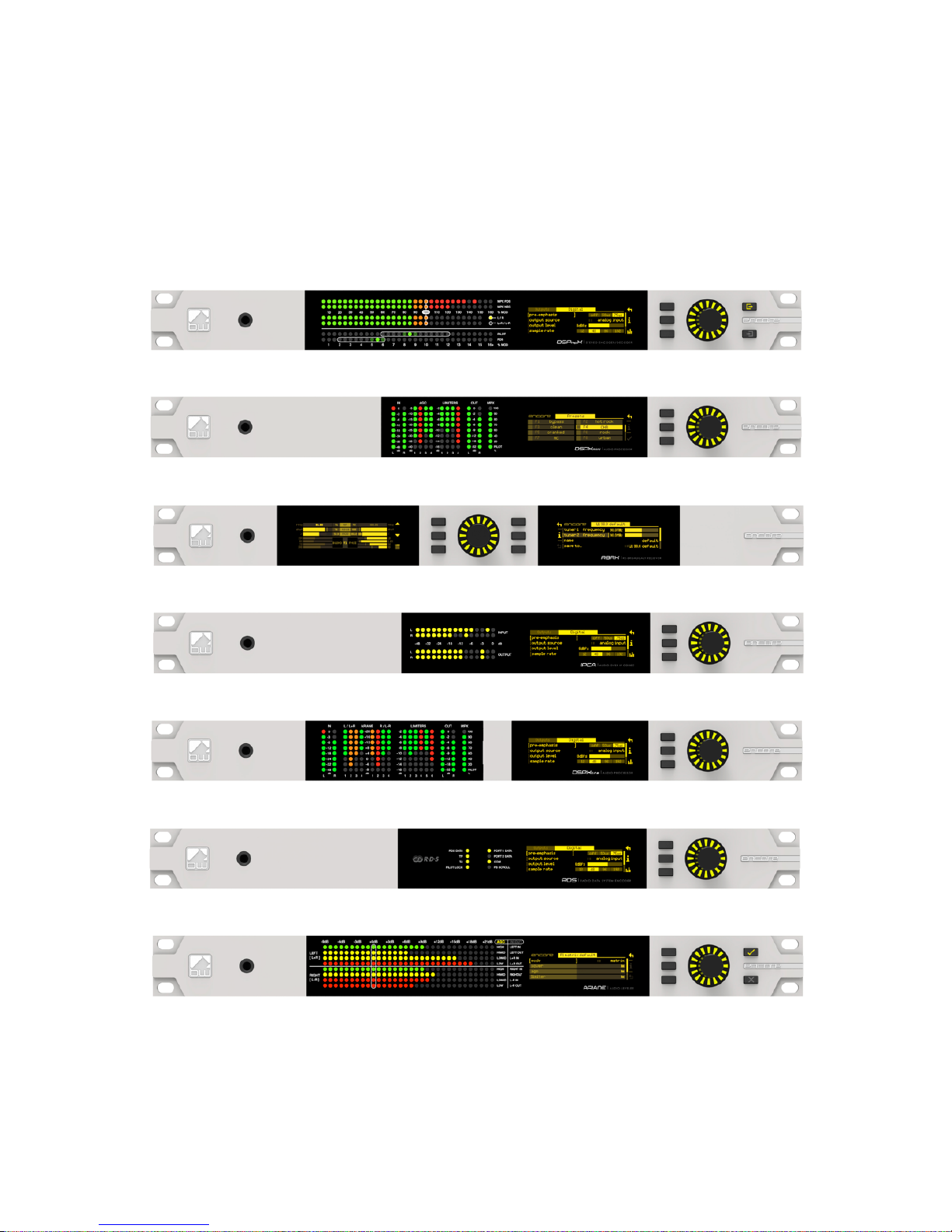
Front & Rear Panels 5
The Encore range uses several versions of the front panel, each using similar components
and featuring the same method of operation.
!
Multicolour LED
matrixes for level
displays
OLED displays for
menu system and
analysis
Scroll knob, LED ring and
buttons for control and
setup
Headphon e
output for high
quality audio
monitoring
Page 10
5 - 2
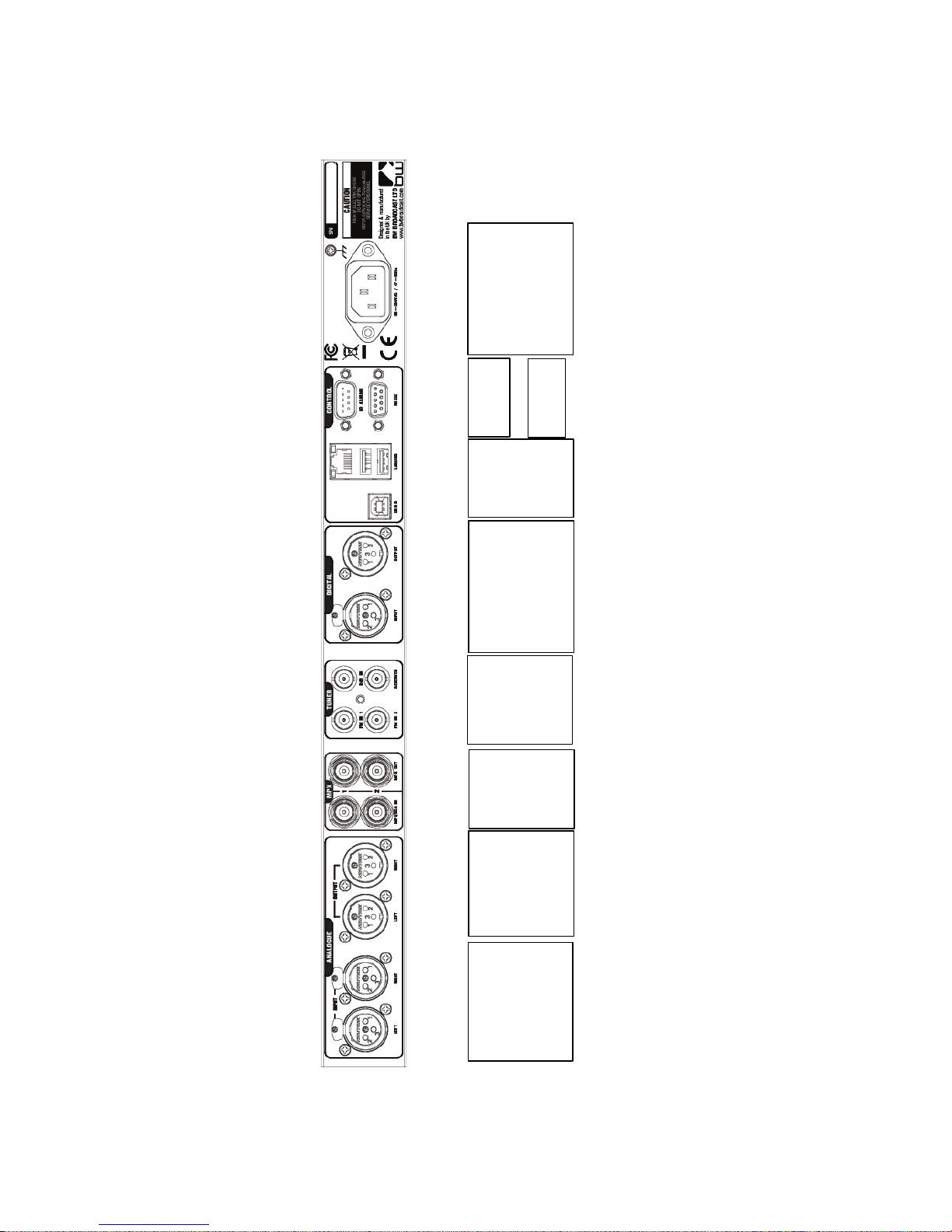
Note: Some connectors on the rear panel are non-functional where appropriate to the
product.
Analog audio
inputs
Pin 1 0v
Pin 2 + (hot)
Pin 3 – (cold)
Analog
audio
outputs
Pin 1 0v
Pin 2 + (hot)
Pin 3 – (cold)
MPX
inputs
and
outputs
(BNC)
Antenna
inputs
(BNC)
AES/EBU Digital
input and output
Pin 1 0v
Pin 2 + (hot)
Pin 3 – (cold)
USB
and
Ethernet
(LAN)
Events &
Triggers
Mains power
(IEC)
90-260v AC, 25w
RS232
Page 11
6-1
User Interface 6
6
NAVIGATING
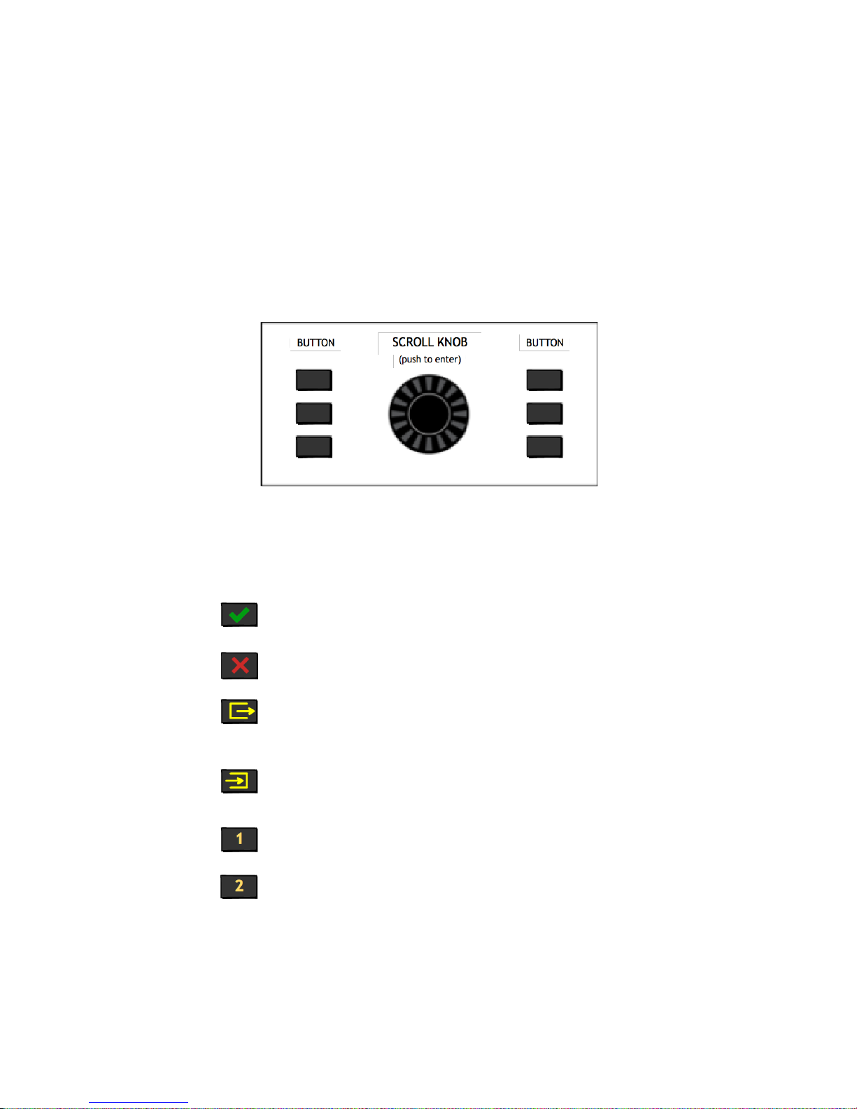
The Encore products have an intuitive interface based around a pushable scroll knob,
surrounded by a ring of LEDs, with a series of buttons. Some products have three buttons,
some five and some six.
The buttons can be ‘soft keys’, and perform various functions denoted by icons shown
adjacent to them in the displays, or may be function-specific - in which case the buttons
are illuminated with the following symbols:
ONLINE
OFFLINE
DECODE
ENCODE
INPUT 1
INPUT 2
Audio is passing through the unit and is being
processed.
Input is connected to output and audio is not being
processed.
The unit is operating as a stereo generator, or
encoder, producing a composite (MPX) output
signal from the analog or digital inputs!
The unit is operating as a stereo decoder,
producing discrete left and right, analog and
digital outputs from a composite signal input.!
Switches the unit to tuner 1 or MPX input 1.!
Switches the unit to tuner 2 or MPX input 2.!
Page 12
6-2
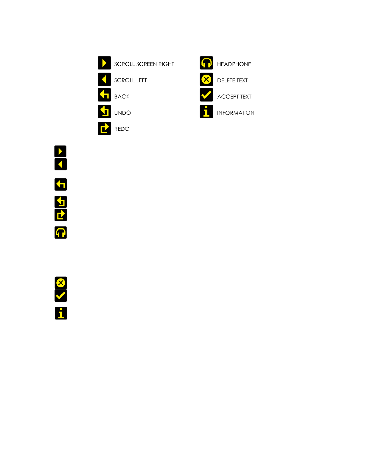
The icons that can be shown against the softkeys are as follows:
If the ‘scroll screen left’ or ‘right’ icons are displayed, this indicates that there are
additional screens available. Pressing these buttons slides the displays to and
from these other screens.
‘Back’ will move back up one step in a menu tree.
‘Undo’ and ‘redo’ are typically used in an audio processor to perform an
‘A/B comparison’ between two presets, or between a modified and an
unmodified preset.
The ‘headphone’ button, when pressed, will cause the icon to flash indicating
that the headphone level may be directly adjusted by rotating the scroll knob
(rather than having to enter the System | Audio menu as described in Section 8).
This mode will time out after 5 seconds of inactivity, or when the button is pressed
again.
The ‘delete text’ and ‘accept text’ buttons are used when the virtual ‘qwerty’
keyboard is being employed to add or modify text, perhaps to name a preset or
to enter other alpha-numeric strings such as email addresses etc.
While navigating the menus, if an ‘info’ help-text is available for that parameter,
the ‘i’ symbol will illuminate next to a softkey. Pressing this softkey will show the
information; pressing it again (or pressing ‘back’) will dismiss the info.
The Encore’s high-quality OLED displays show various levels and parameters, plus allow
selection and editing of the various settings throughout the unit.
The menu system is navigated by rotating the knob to highlight an item and pushing it to
open a submenu, or to select the parameter for editing.
While in a submenu, pressing the ‘back’ softkey will return to the parent menu.
Page 13
6-3
EDITING A PARAMETER
To edit a parameter, navigate to it in the menu using the knob - square brackets [ … ]
will surround the currently highlighted parameter. Press the knob to select the
parameter, then rotate the knob to change it.
Changes happen immediately as you turn the knob; press the knob again to keep the
change; alternatively press the ‘back’ softkey to revert without changing.
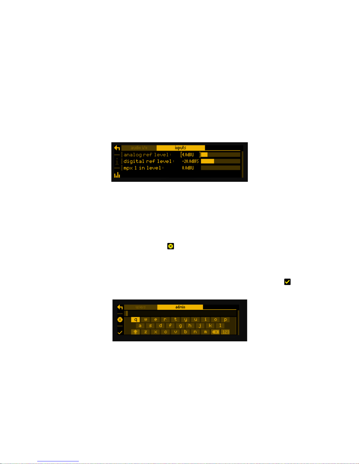
The parameter setting will be shown on the OLED screen, numerically and with a
progress bar, as shown below:
EDITING A TEXT FIELD
When editing a text field, such as the system name or a preset name, a ‘qwerty’
keyboard will be shown on the OLED display.
Highlight the letter to be used by turning the knob and press to select. To delete a letter,
use the softkey adjacent to the ‘X’ icon .
To switch to a numerical keyboard, select the ‘123’ button with the scroll knob and press
to select.
To accept and save the new text, press the softkey indicated by the ‘check' icon .
Page 14
7 - 1
Installation 7
The RBRX Encore is extremely versatile, and be used in a number of ways:
§ Monitor receiver;
§ Rebroadcast receiver;
§ Stereo coder;
§ RDS generator;
§ A combination of these!
Please see section 11 for a comprehensive routing diagram.
Page 15

7 - 2
7.1 QUICK SETUP
To get you started, here is a description of the unit’s configuration with some common
uses:
CONFIGURING AS A MONITOR RECEIVER
1. From the home screen, highlight ‘presets’ and push the knob to enter the
presets submenu.
2. Preset 1 will be highlighted, along with the frequency that tuner 1 is currently set
to. Press the knob to enter the preset 1 submenu.
3. Scroll to highlight ‘tuner 1 frequency’, press the knob to select, then turn it to
enter the desired frequency. Press the knob to save this, then press ‘back’ three
times to return to the home screen.
4. Enter ‘system’, ‘audio i/o’. Highlight ‘outputs’ and press the knob to open the
submenu.
5. If you’re using the analog outputs, change ‘an output source’ to ‘tuner 1’; if
using the digital output, change ‘dig output source’ to ‘tuner 1’. You may also
need to change the ‘digital sample rate’ to that the equipment to which is
connected requires.
6. If you’d also like to monitor via headphones, set ‘headphone source’ to ‘tuner 1
audio’.
7. Connect a receive antenna to the rear-panel ‘FM1 IN’ connector.
8. Connect the analog, or digital outputs to a suitable amplifier/speakers or
mixing desk etc.
Note: The diagram shows only one antenna connected; The RBRX Encore has two
antenna inputs and two separate tuners – later in this manual we will learn the benefits
and applications of this.
Listen with pleasure!
Page 16

7 - 3
CONFIGURING AS A REBROADCAST RECEIVER
…with the received composite audio feeding the transmitter.
1. Carry out actions 1 through 3 in Section 7.1 above, to set tuner 1 to the
frequency of the transmission you wish to rebroadcast.
2. From the home screen, enter the ‘system’ menu and navigate to the ‘audio i/o’
submenu.
3. Enter the ‘outputs’ submenu.
4. Set the ‘mpx 1 source’ to ‘mpx generator’.
5. Set ‘mpx out level’ to your desired level.
6. Navigate to ‘MPX generator’, enter that menu and set the source to ‘tuner 1
audio’.
8. Set the pilot level to your desired level, probably 9%.
9. Press ‘back’ three times to return to the home screen.
Note: You could set ‘mpx 1 source’ to ‘tuner 1 mpx’ – then the received mpx signal
would pass through the unit unmolested; however you will not then be able to feel the
benefit of the complex ‘FMSI’ dsp-based signal processing, which can recover very
good stereo audio from a poor or noisy receive signal.
This is because, in the RBRX Encore, the ‘FMSI’ dsp signal processing is carried out in the
demodulated audio domain. We recommend you take advantage of this powerful
feature.
Connect the rear-panel ‘mpx1 output’ socket to your transmitter, and connect a
receive antenna to the rear panel ‘FM 1 IN’ connector.
Of course, if you’re using the RBRX Encore as a rebroadcast receiver, you can still
configure it as a monitor at the same time. You could also configure the audio and/or
headphone outputs to carry audio from tuner 2, which could be on another frequency,
including the frequency you’re transmitting, so you can hear your transmitted audio!
Page 17

7 - 4
The two tuners in the RBRX Encore are fully independent and can be set up on two
different frequencies (unless you’re using the ‘Diversity’ feature).
This gives you the opportunity of having a main and a backup frequency for
rebroadcast.
To do this, connect an antenna pointing at your main site to tuner 1, and set that tuner
to the main frequency.
Connect another antenna to tuner 2, pointing at your backup site, and tuned to that
site’s frequency.
Set the audio routing as above, but in addition, navigate to System | Events, and set up
an event the trigger of which is RSSI 1 – the signal strength being received by Tuner 1.
Set the condition to be ‘less than’, and the value to be one below which you consider
that signal to be too poor to use – say 30dBuV.
Set On Delay to maybe 5s, leave Load Preset at ‘none’, and set Revert to ‘delay’. Set
this delay to 5s.
In Set/Change, select ‘mpx gen src’, and set the To field to ‘tuner 2 audio’.
Now, when the signal being received by Tuner 1 drops below 30dBuV (such as when
that transmitter has gone off air) the RBRX Encore will wait 5 seconds, then switch to
relaying the signal being received on Tuner 2.
When the transmitter Tuner 1 is listening for returns, the RBRX will wait 5 seconds and then
return to relaying the main transmitter.
We suggest using delays of around 5 seconds to preclude false switching because of
noise bursts or if the transmitter takes time to stabilise when it returns to air.
In the same Events section, you could also set up the RBRX Encore to email you when
the main transmitter’s signal fails.
More anon.
!
Page 18

7 - 5
CONFIGURING AS A STEREO GENERATOR
1. Go to ‘system ‘, ‘audio i/o’, ‘outputs’, and set ‘mpx 1 source’ to ‘mpx
generator’.
2. In ‘system’, ‘mpx generator’, set source to ‘analog audio’ or ‘digital audio’
depending on how you’re feeding the unit.
3. Scroll to, and set your desired pilot level.
If you wish to add or modify RDS information to your composite stereo signal,
please then do the following:
4. From the home screen, navigate to ‘presets’, ‘preset 1’, ‘rds’… and set the RDS
parameters as you need.
5. Then back in ‘mpx generator’, set the RDS level to the percentage you need,
probably 2-4%.
And that’s it.
A more detailed description of the configuration of the RBRX Encore follows:
!
Page 19

THE SYSTEM MENU
This menu contains all the fundamental unit configuration settings, and should be the first
place you go after taking the Encore out of its box!
These settings are peculiar to the installation, perhaps the transmitter site itself, as
opposed to the following ‘Presets’ section (Section 9) which are particular to the exact
usage and model of the unit.
Power the unit up, and from the home screen, highlight and press the ‘system’ button:
You’ll now see a list of submenus:
Audio i/o: Contains all audio input and output settings, as well as output
routing selections.
(Not present in all Encore products)
MPX generator: Settings for the mpx (‘composite’) generator.
(Not present in all Encore products)
Events: A comprehensive events/alarms/scheduling system.
Time: Manually setting the unit time and date, or automatically setting
this via ntp.
Users: Set up admin user and standard users.
Communication: A sub menu containing settings for identity, ethernet,
email, web remote, snmp, telnet, logging and RS232.
About: Unit information and power supply status.
Note: Certain menu items will be different or not present in some products, as
appropriate to their features.
Let’s take some time to discuss the contents of each of these menus:
Page 20

8.1 AUDIO I/O
(Certain menu items are omitted in some products in the Encore range).
Within this there are two submenus – ‘inputs’ and ‘outputs’.
‘Inputs’ allows you to set the operating level of the unit when referenced to the rest of
your installation. For both analog and digital reference level, please set these to your
maximum normal operating level.
For example, if you will be feeding analog audio into the unit that may reach but never
exceed +12dBu, set the ‘analog ref level’ to +12. (For PPM users, PPM4=+4, PPM5=+8,
PPM6=+12).
Similarly, if your digital levels may meet but not exceed -10dBFS, set ‘dig ref level’ to -10.
‘Outputs’ allows you to set output levels from each physical output, and choose what
source feeds those outputs.
The sections of this submenu are:
An (analog) output source: none
analog audio
digital audio
tuner 1 audio
tuner 2 audio
test tone (a 1kHz sine wave)
diversity
Analog output level: -18dBu to +24dBu
Dig (digital) output source: none
analog audio
digital audio
tuner 1 audio
tuner 2 audio
test tone
diversity
Dig output level: -20dBFS to 0dBFS
Dig output sample rate: 48kHz
96kHz
192kHz
MPX 1 source: none
mpx in 1*
tuner 2 mpx*
mpx generator
pilot tone
rds
MPX 1 out level: 0dBu to +12dBu**
Page 21

MPX 2 source: none
mpx in 1*
tuner 1 mpx*
tuner 2 mpx*
mpx generator
pilot tone
rds
MPX 2 out level: 0dBu to +12dBu**
Headphones source: none
analog audio
digital audio
tuner 1 audio
tuner 2 audio
test tone
diversity
Headphone level: 0 to 100%
For convenience, the headphone source and headphone level settings are duplicated
directly under the ‘audio i/o’ menu.
* Note that if ‘tuner 1(or 2) mpx’, or ‘mpx in 1’ is selected as the source for an mpx
output, the received signal merely passes through the unit, unaffected by the ‘fmsi’
signal processing (please see section 9 of this manual).
** The mpx output level adjustments only affect the output of the internal mpx
generator. If the mpx (1 or 2) output source is set to ‘tuner 1 (or 2) mpx’, the output level
is fixed at +6dBu.
8.2 MPX GENERATOR
(Not present in all Encore products)
This menu controls the on-board stereo generator (‘MPX’ meaning multiplex, sometimes
known as ‘composite’).
The stereo generator includes a composite clipper. With a drive level of 0dB, this has no
effect; above that it will become active and clip the MPX signal. The clipper contains
RDS/SCA protection filters, also there is a pilot protection filter option.
The audio clipper protects the MPX generator from peak excursions and overshoots in
the source audio. It is distortion-cancelling and anti-aliased.
Furthermore, there is an ‘overshoot compensator’ which handles any overshoots from
the main clipper, and restricts the audio bandwidth to 15kHz.
The MPX generator menu contains the following parameters:
Page 22

Source: none
analog audio
digital audio
tuner 1 audio
tuner 2 audio
diversity
test tone
Preemphasis: 50uS, 75uS, off.
Pilot level: 0 to 12% in 0.1% increments
RDS level: 0 to 5% in 0.1% increments
Audio clip drive 0 to 12
O-sh compensate drv -3 to 9
(overshoot compensation drive)
Comp (composite) clipper drive: -0.5 to 2
Pilot protection no / yes
8.3 EVENTS
This is a very comprehensive monitoring, events and alarms section. It allows changes to
be made to the configuration of the Encore unit resulting from external sources via the
Events and Triggers port, or from conditions detected from incoming signals – be they via
the tuners or the audio inputs.
It is really a telemetry system in itself. As events can be triggered from external sources,
you can use it to monitor other equipment in your facility, even door-open sensors,
intruder alarms, in fact anything that can pull one of the four input pins to 0v.
The system is designed in a very intuitive, conversational way. “When this happens, for
this long, do these things. Then when it’s stopped for this long, do that.”
In the ‘events’ menu, the first sub-menu is ‘GPO pin config’. In this section, with the
‘mode’ parameter, you can determine what each of the four GPO pins do:
1. Switch as an event action (see later);
2. Track tuner 1 signal strength;
3. Track tuner 2 signal strength;
4. Track analog input level;
5. Track digital input level.
6. Track unit temperature.
With option 1, the pin is a ‘digital’ output (i.e. either ‘on’ or ‘off’). With options 2 through
6, the pins act in an analog manner, outputting 0 – 5v which will track whatever signal
you have selected.
Page 23
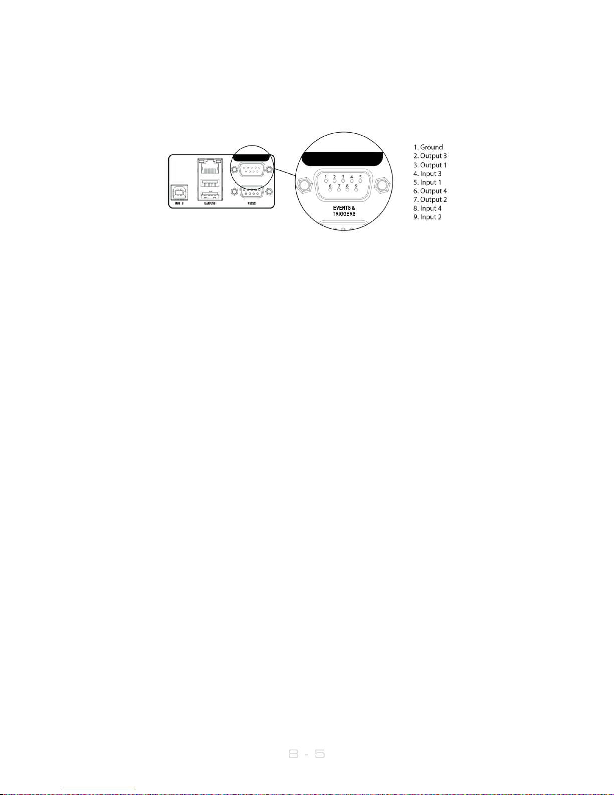
The other option available in this menu is ‘polarity’ – where you can set each pin to
output either active Hi-Z (high impedance) or active low (i.e. connected to 0v).
The Events and Triggers port pinouts are:
Next is the list of the 8 available events, each of which can perform a variety of actions
when triggered.
Please highlight and select one of the events.
To set up an event:
1. For now, leave the ‘active’ setting ‘off’.
2. Select from the list what you want to ‘trigger’ the event; the choices are tuner
signal strengths, tuner audio levels, analog and digital inputs and outputs, unit
temperature and the status of the GPI pins.
3. Then select what ‘condition’ should cause the trigger – more than, less than
or in some cases equal to or not equal to.
4. Next, set the ‘value’ – the range here varies according to the trigger type.
5. Next is the time to wait after triggering before the event is activated (for
example, wait for 15 seconds of silence before activating the event).
6. ‘revert’ determines what happens when the trigger condition ends – does the
unit go back to its previous condition, and if it does, is it immediate or delayed?
7. Next you can set this revert delay.
The next parameters set what actions the event causes. You can set it to do any or all of
the following:
load a different preset;
change tuner frequencies;
change various output sources;
switch one of the GPO pins;
send an email;
send an snmp trap message.
Note that if you select ‘load preset’ as an action, the ‘revert’ function is greyed out and
not available. This is because a change of preset can involve a change of frequency of
Page 24

both tuners, so in this case there’s no way the Encore can know when or if the event
trigger has ended.
When you’re happy with the event setup, return to the top of the event menu, and
switch it to ‘active’.
Exit from the ‘events’ menu by repeatedly pressing ‘back’ until you reach the home
screen.
8.4 TIME
This menu allows you to set the unit’s time and date, or if it has network access to an ntp
server, to use that.
The following parameters can be accessed:
uptime: A display of the time, in hours, minutes and seconds that the
Encore has been powered up.
time: Allows manual setting of date and time.
ntp: off / on (whether to use ntp or not)
update now: ‘run’ – pressing this forces an immediate update of system
time via the ntp server.
host: the ntp hostname, e.g pool.ntp.org or an IP address.
period: How often an ntp time update occurs – every 1hr, 12hrs or
24hrs.
8.5 USERS
This menu allows you to define parameters for people who will have access to the
Encore unit, and who will be able to log in via the web remote.
There are four users available:
admin A ‘power-user’ who is able to edit/change settings as well
as view all screens;
user 1, 2, 3 These users can be limited to either merely viewing settings and
screens, or controlling them in the same way the admin user can.
However, a non-admin user with ‘control’ privilege cannot add or
change any other user’s details.
Within the users menu, you are able (if you’re an admin) to set the users’ password, their
email addresses and their privileges.
Page 25

[In an imminent firmware release, ‘security’ will be implemented which will utilise these
settings more comprehensively].
8.6 COMMUNICATION
This menu contains the following submenus:
Identity: Allows a unit name, site number and lat/long (‘GPS position’) to be
set. This is useful when managing multiple units via the web
interface, and when receiving emails from the ‘events’ section, so
it’s obvious where the email came from.
Ethernet: Allows you to set the following parameters, relevant to the IP
network the Encore is connected to:
DHCP: ‘on’ if your network has a DHCP server from which the Encore
will be able to derive network parameters automatically; set to
‘no’ to define these settings manually.
DNS: ‘on’ to use the dns server derived above, or ‘off’ to manually enter
a DNS server.
IP: Manually enter he unit’s IP number.
Subnet mask: Manually enter the unit’s subnet mask appropriate to your
network.
Gateway: Manually enter the gateway IP number (usually the IP number
of your router).
DNS 1: Manually define one DNS server IP number.
DNS 2: Manually define an alternate DNS server.
MAC: A display of the unit’s mac address
Link: Shows ‘up’ if the unit’s ethernet connectivity is working, ‘down’ if
not.
Email: Allows you to set up the email communication of the
Encore:
Sender: the email address of the Encore, e.g encore-
01@stationname.com
Mail method: ‘BW’ to allow the unit to send emails via the BW Broadcast
monitoring system; ‘SMTP’ if you wish to send the
emails via your own SMTP server;
Page 26

(if ‘SMTP’ is selected, further settings will appear allowing you to specify
the name of this server, it’s authentication method and if necessary the
SMTP password).
Test: This submenu allows you to send a test email to one of the
users (previously defined in 7.1.5 ‘Users’ in this manual).
Web remote: Here you can turn on or off access to the Encore
by the ‘Encore web remote’ software, and to define the
port that this web remote will use – default is the common
http port 80.
SNMP: Settings for using Simple Network Management Protocol, to
allow the Encore to communicate with other
telemetry and monitoring systems.
The SNMP ‘MIB’ file is accessible when the unit
has an ethernet connection, by navigating to http://[unit
IP]/Encore.mib
Telnet: Set Telnet access on or off, and define the port.
Logging: Sets up a UDP connection to an external logging server,
and/or log to file o via a serial connection.
RS232: Enable/disable the rear-panel RS232 (serial) connector, and
sets the baudrate to be used.
8.7 ABOUT
A display of unit details, serial number, hardware and software versions etc. This
information may be requested by a BW Broadcast support technician if you need live
assistance. The OLED ‘sleep’ timeout is also set here.
RESTART AND FACTORY RESET
There is also a ‘restart’ and a ‘reset to defaults’ command in this menu. Beware – ‘reset
to defaults’ will remove any settings you have modified in Presets, and everything you
have entered in System.
…which includes the Ethernet settings – so this isn’t a good thing to do if you’re
connected remotely, as you may lose IP connectivity.
STATUS
This submenu shows values of current hardware parameters:
PSU voltage; PSU current; PSU power; fan voltage; fan state; temperature; plus fan speed
control – which should be left set to ‘auto’ unless otherwise advised by a BW Broadcast
support technician.
Page 27

9 - 1
Presets Configuration 9
THE ‘PRESETS’ MENU
This menu can be thought of the same way as a set of presets on a car radio or
standard hi-fi tuner. These settings are particular to the stations or frequencies being
received.
From the home screen, highlight the ‘presets’ button, and press the knob.
You will be presented with the following screen:
This shows the list of presets – those prefixed with the letter F are factory presets, the prefix
U indicates a user preset location.
The rest of the preset locations will become visible if you scroll down the list.
To the left of each preset name is the ‘status block’.
The current preset is shown highlighted – if you scroll away from this, the status block to
the left of the preset name remains filled to indicate that this is the preset that is currently
loaded.
If this block shows the letter A, this indicates that the preset has been selected by an
‘action’ from the ‘events’ section of the RBRX Encore (see section 8 in this manual).
If the block shows the letter S, the preset has been selected by a ‘schedule’ event.
If a preset has been edited but not saved, an asterisk * is shown in this block.
If multiple statuses are active, the priority is: A, S, *, .
In addition, in this screen, softkey 5 shows the i symbol. Pressing this will display extra
information about the highlighted preset, such as tuner 2 frequency, RDS station name (if
available) and date/time the preset was created and last used.
Page 28

9 - 2
The factory presets cannot be overwritten, however they may be used as good starting
points for you to create your own presets, which can then be saved in one of the user
preset locations.
The factory presets are:
F1: Default: Contains a group of settings determined to provide good
performance in strong receive signal conditions.
F2: Soft: Settings which apply light processing designed to enhance the
receive signal under less than perfect conditions.
F3: Hard: Settings which apply much more signal processing, to enhance
and restore extremely poor signals.
F4: Measure: Signal processing is bypassed, to allow measurements of the
incoming signal with it unaffected by any processing within the RBRX
Encore.
9.1 LOADING A PRESET
To load a preset, scroll to it using the knob, when your desired preset is highlighted, press
softkey 6 – which you may have noticed is now displaying a ‘tick’ icon.
Or you can scroll to the preset and press the knob – this will load the preset and enter
preset edit mode.
If you have a user preset loaded, and you then load one of the factory presets, the
receive frequency and deemphasis setting is not altered. The RBRX Encore will in this
case apply the rest of the processing and refinements contained within that factory
preset.
!
Page 29

9 - 3
9.2 EDITING A PRESET
To edit a preset, scroll to it and press the knob. This action will load the preset too – as the
configuration is actually edited ‘live’.
As soon as a preset is modified, an asterisk * appears in the status block, and softkey 6
displays the undo icon.
An asterisk will also be shown in the top line of the edit screens as soon as any
modification is made, to remind you that the preset is in a modified state.
Pressing the ‘undo’ button will revert the preset (and therefore the live state of the RBRX
Encore) to its unmodified and saved state. Once pressed, the ‘redo’ symbol is shown
against softkey 6. Guess what happens if you press it!
If you attempt to exit the preset edit menu and load another preset before saving your
changes, a warning dialog box will appear, informing you that if you continue, your
changes will be lost, and asking if you wish to continue, or go back to save your
modified preset.
Once you press the knob to enter the preset edit mode, the first submenu shows:
Tuner 1 frequency: Allows quick-setting of tuner 1 receive frequency.
Tuner 2 frequency: Allows quick-setting of tuner 2 receive frequency.
Preset name: Selecting this brings up a ‘qwerty’ keyboard, so that an
optional friendly name can be appended to the default
preset name, which is U1 98.0, for example. The first part of
the preset name is always the preset number followed by
the frequency of tuner 1.
Save to: Allows the settings contained within the current preset to be
saved back to itself (not if it’s a factory preset) or to any
other user preset slot.
Note: If you try to save to a preset slot other than the one you’ve modified, a pop-up will
warn you that you are about to overwrite the contents of that preset, and asking you if
you’re OK with that.
Copy t1 to t2: Causes the immediate copy off all tuner 1 settings to
tuner 2.
This is useful if you have set up all your settings in tuner 1 and wish to duplicate them in
the other – either for use in ‘diversity’ (see 8.4 in this manual) or if the second tuner is
going to be used to receive a second frequency as a backup (obviously you’d only
have to change the tuner’s frequency then).
Diversity: Sub-menu which contains ‘diversity active yes/no switch
and the ability to adjust diversity weightings. Please see
section 8.4, below, for a detailed explanation of this
powerful feature.
Page 30

9 - 4
9.3 TUNER 1 AND TUNER 2
The contents of the ‘tuner 1’ and ‘tuner 2’ menus are identical:
Frequency: Another place to set the tuner’s frequency.
Deemphasis: Set de-emphasis to suit your region, 50 or 75µS. For test and
measurement purposes, it’s also possible to select ‘off’.
Note: the following advanced functions allow access deep under the hood to the many
complex and advanced processing parameters that makes the RBRX Encore unique in
its performance as a rebroadcast receiver.
These parameters have been set up in the factory presets F1 to F4 by our design team,
and do not necessarily need to be adjusted by the user.
We include them here for use by power users who wish to delve deep, and create
extremely complex and specific presets.
Channel EQ: An adaptive filter to improve reception when multipath
interference is being encountered. On/Off.
Mpath suppression: Reduced audibility of distortion caused by multipath
interference. On/off.
Noise blanker: Detects and supresses noise pulses. On/off.
Audio trim: Fine adjust of the tuner’s audio level to account for
discrepancies in the deviation level of the received signal.
IF filter: Settings for the IF bandwidth of the tuner. Entering this submenu will
allow you to manually adjust the bandwidth, or set it to ‘auto’.
Stereo blend: A system for the simple handling of stereo reception in weak signal
conditions. Does not recover stereo signal, merely modifies stereo
separation to mask the effects of the poor signal. Parameters are:
Time: Defines the weak signal handling for the level detector and
noise/multipath detectors.
Mod: Enables modulation dependency and sets sensitivity.
Level: Sets level sensitivity and enables slow and fast timing.
Noise: Sets noise sensitivity and timing.
Multipath: Sets multipath sensitivity and timing.
Min: Optionally allows a minimum amount of stereo separation
reduction under good signal conditions.
Max mode: Disables stereo blend function, for test and measurement purposes.
Page 31

9 - 5
St improvement: A submenu containing controls for a complex, proprietary DSP-
processing system (FM Stereo Improvement, ‘FMSI’) which
improves stereo performance in less than perfect signal conditions.
You can select ‘hi blend’ or ‘FMSI’. The ‘hi blend’ setting provides settings for the
traditional method of FM weak signal handling, in which the HF component of the left
and right audio channels is ‘blended’ together to reduce noise, or hiss, which becomes
prevalent in the stereo domain. The parameters for hi blend are:
Time: Defines the weak signal handling response times for the level
detector and noise and multipath detectors. Fast and slow
response times are available for dual timer functionality, with
enable options for the level, noise and multipath parameters.
Level: Sets the level sensitivity and enables slow and fast timing.
Noise: sets the noise sensitivity and enables slow and fast timing.
Multipath: as above, for multipath.
Max: sets the maximum amount of blend to occur in very poor signal
conditions.
Min: optionally defines the minimum amount of blend, as realised in
good signal conditions.
The ‘FMSI’ alternative introduces an advanced, multiband processing system for
recovering good audio quality and stereo performance from weak or noisy signals. The
parameters are:
Blend time: Defines the weak signal handling response times.
Blend gain: Defines the weak signal handling sensitivity for the four available
audio bands.
Blend bias: Defines how the system operates with good quality reception but
low modulation levels.
The performance of the Stereo Improvement can be monitored on two screens (one for
each tuner), which are available on the left OLED display:
!
Page 32

9 - 6
Meters on this screen are:
IFBW: IF bandwidth.
USN: Ultra-Sonic Noise – sometimes known as MPX noise.
RSSI: Signal Strength.
MPTH: Multipath.
..in the ‘blend’ section of the screen:
SM: Soft Mute.
HC: High Cut.
SB: Stereo Blend.
HB: High Blend.
..in the ‘fmsi’ section of the screen:
LO: Low band.
2.2k: The 2.2kHz band.
5k: The 5kHz band.
HI: High band.
We recommend for normal use, FMSI is selected. Indeed, our factory presets ‘f1 default’
and ‘f3 hard’ employ this to good effect.
Please note that since Stereo Improvement (FMSI) operates in the demodulated audio
domain, its benefits are not available if you select ‘tuner mpx’ as a source for one of the
mpx outputs. Even if you are using an mpx output to feed your transmitter, we
recommend selecting ‘mpx generator’ as the source for the MPX output, and ‘tuner 1(or
2) audio’ as the MPX generator source (see section 7.1).
Softmute: Settings to control how the signal will mute if the signal deteriorates.
High cut: Timing and quality sensitivity settings for a low pass filter, which can help
with weak signal handling.
Low cut: A high pass filter, useful for removing subsonic noise.
!
Page 33

9 - 7
9.4 RDS
This submenu allows you to set the RDS/RBDS parameters of the MPX/composite output
signals.
It’s very clever, in that it allows you, if you wish, to use some of the RDS parameters being
received, and others locally generated.
This means that you could, for example, set a slightly different PS (station name) for the
rebroadcasted signal, so you can tell by looking at the radio’s display which particular
transmitter you’re tuned to, or to alter the AF (alternative frequency) list to make it more
efficient by not including frequencies not audible within that transmitter’s service area –
all the time maintaining the rest of the original RDS data.
To set all locally-generated RDS info, please set ‘source’ to ‘local’;
To set all received RDS info, set to ‘rec’d’ (the tuner which is supplying this data is the
one set as the source of the MPX generator [see section 7.2]);
To set a mixture of the two, please set this parameter to ‘custom’, then enter the custom
data you wish to use in the rest of the RDS parameters.
Please note: If the MPX generator is receiving it’s audio from either the analog or digital
inputs (described in section 7.2), obviously there is no received RDS data. In this case, the
RBRX Encore will derive the RDS data solely from the ‘local’ settings.
So if you are using the analog or digital inputs as a backup source, it’s important that all
the ‘local’ parameters are set, otherwise when you’re on backup audio there won’t be
any RDS!
This does mean that you could be very clever, and slightly alter your station’s PS (station
name) in the ‘local’ PS setting, maybe add a *, so that you have an indication on your
radio that the station has gone to backup audio!
RDS SETTINGS
Encoding: rds/rbds (rbds for the US, rds for rest of world)
Source: off no rds.
local all data locally generated.
rec’d all data as received.
custom you choose the mixture of local or original
data.
PI source: local locally-specified PI code.
rec’d received PI code.
PI: enter local PI code.
PS source: local locally specify PS (station name).
rec’d use received PS.
PS: enter local PS.
Page 34

9 - 8
Stereo source: local locally specify ‘stereo’ setting.
rec’d use received ‘stereo’ setting.
Stereo: off/on setting to use if ‘local’ selected.
Dynamic pty src: local locally specify dynamic pty (program type).
rec’d use received setting.
Dynamic pty: off/on setting to use if ‘local’ selected.
TA source: local locally specify ta (traffic announcement)
setting.
rec’d use received setting.
TA: off/on setting to use if ‘local’ selected.
TP source: local locally specify tp (traffic programme) setting.
rec’d use received setting.
TP: off/on setting to use if ‘local’ selected.
MS source: local locally specify music/speech setting.
rec’d use received setting.
MS: music/speech setting to use if ‘local’ selected
PTY source: local locally specify pty (program type).
rec’d use received pty.
PTYRDS: program type list to use if locally generated, in rds
format.
PTYRBDS: program type list to use if locally generated, in rbds
(US) format.
PTYN source: local locally specify (pty name – more specific pty
name) setting.
rec’d use received ptyn setting.
PTYN: ‘qwerty’ keyboard allows entry of more specific pty name.
RT source: local locally specify Radio Text info.
rec’d use received RT info.
RT: Radio Text info to use if ‘local’ selected.
AF: allows entry of alternative frequency list.
!
Page 35

9 - 9
9.5 DIVERSITY
!
This powerful feature enhances the performance of the RBRX Encore, adding single
frequency diversity.
In some circumstances, it is desirable to provide the receiver with two RF inputs carrying
the same signal, and allow the receiver to dynamically and intelligently ‘choose’ which
signal is the best one to use.
Situations where this may be beneficial include particularly distant reception, where
atmospheric conditions may cause reception to deteriorate because of ‘ducting’ –
causing fade-outs, situations where there is a tidal water path between transmitter and
receiver, and sites where local topography or building clutter can cause polarisation
changes and increase multipath distortion.
Such problems can be ameliorated by the installation of two receive antennas, perhaps
one high up a tower and the other low down, or one vertically polarised and the other
horizontal.
The RBRX Encore utilises powerful digital signal processing to analyse the signals being
received by both tuners, and seamlessly switches between them to provide the best
possible useable signal.
This decision is based on an average of certain criteria including signal strength,
multipath, USN (ultrasonic noise, sometimes called ‘MPX noise’) over a rolling 1-second
window; tuners are switched by crossfading from one to the other, this action taking
10mS.
The weightings of these criteria are preset, but can be adjusted if you require by
entering the ‘weighting’ submenu under ‘diversity’.
If you wish to use the diversity feature, please switch ‘diversity’ to ‘on’, in the menu at
presets | preset x (see section 8.0), and select ‘diversity’ in the source selections for the
Page 36

9 - 10
mpx generator source and the audio output sources, as appropriate, as described in
Section 7 of this manual.
Note that once ‘diversity’ is switched on, the frequency of tuner 2 will be automatically
locked to that of tuner 1. A pop-up warning will appear if this action will change the
frequency of tuner 2.
We recommend in this case that you use the ‘copy t1 to t2’ function (described in 8.2
above) initially, to ensure both tuners are setup identically; you can of course
subsequently modify the parameters if you wish.
The performance of the diversity system can also be monitored on the tuner status
display, by means of a sliding bar, which represents the ‘quality’ of the signal being
received by the tuners.
The tuner with the best quality reception will be the one being routed to the ‘diversity’
output; on this display, the ‘active’ tuner and its frequency is highlighted.
This concludes the description of the ‘preset’ menu.
Take a few moments rest, you’ve earned it!
...
....
.....
!
Page 37

10 - 1
Menu Structure 10
SYSTEM >
AUDIO I/O >
INPUTS >
analog ref level (-18dBu to +12dBu)
digital ref level (-30dBFS to -10dBFS)
mpx1 in level (0 to +12dBu)
OUTPUTS >
an output source (none/analog audio/digital audio/tuner 1 audio/tuner2
audio/diversity/test tone)
an output level (-18dBµ to +24dBµ)
dig output source (none/analog audio/digital audio/tuner 1 audio/tuner2
audio/diversity/test tone)
dig output level (-20dBFS to 0dBFS)
dig sample rate (48kHz/96kHz/192kHz)
mpx 1 source (none/mpx in 1/tuner 2 mpx/mpx generator/pilot tone/rds)
mpx 2 source (none/mpx in 1/tuner 1 mpx/tuner 2 mpx/[mpx
generator/pilot tone/rds)
mpx 1 level (0dBµ to +12dBµ) 8dBu
mpx 2 level (0dBµ to +12dBµ)[8dBu
headphone source (none/analog audio/digital audio/tuner 1 audio/tuner 2
audio/diversity/test tone)
headphone level (0-100%)
headphone source (none/analog audio/digital audio/tuner 1 audio/tuner 2 audio/test
tone)
headphone level (0-100%)
MPX GENERATOR >
source (none/analog audio/digital audio/tuner 1
audio/tuner 2 audio/diversity/test tone)
preemphasis (50uS/75uS/off)
pilot level (0 to 12%)
rds level (0 to 5%)
audio clip drive (0 to 12dB)
o-sh comp drv (-3 to 9)
comp clipper drive (-0.5 to 2.0dB)
Pilot protection (no/yes)
EVENTS >
GPO PIN CONFIG >
PIN 1..4 >
mode (dig/ana)
polarity [if ‘dig’ selected above] (HiZ/low)
analog output [if ‘ana’ selected above] (rssi 1/rssi 2/modulation
1/modulation 2/analog input/digital input)
EVENT 1…8 >
active (off/on)
trigger (rssi 1/rssi 2/modulation 1/modulation 2/usn 1/usn 2/multipath
1/multipath 2/analog input/digital input/rds pi 1/rds p1 2/rds ta 1/rds
ta 2/gpi 1/gpi 2/gpi 3/gpi 4)
condition (equal to/not equal to) or (more than/less than)
value (on/off) or [value appropriate to trigger]
on delay (0 to 60s)
revert (yes/no/delay)
delay time (0 to 12s)
load preset (F1 to F4 and U1 to U8)
set/change (none/analog out src/digital out src/mp1 out src/mpx2 out
src/mpx gen src)
to [dependent on choice above]
set GPO pin (none/pin1/pin2/pin3/pin4)
email (none/admin/user1/user2/user3)
send snmp (yes/no)
Page 38

10 - 2
SYSTEM cont… >
TIME >
uptime (display of dd:hh:mm:ss)
time set (hh: mm: ss: mm/dd/yyyy)
ntp (off/on)
update now run [command]
host [name or IP number]
period (1hr/12hr/24hr)
USER >
ADMIN >
password pass [default]
email (email address)
USER 1…3 >
password pass (default)
email (email address)
privilege (view/control)
COMMUNICATIONS >
IDENTITY >
system name (qwerty)
site number (qwerty)
lat/long (xxx.xxx yyy.yyy)
ETHERNET >
dchp (off/on)
dns (off/on)
ip
subnet mask
gateway
dns 1
dns 2
mac
link [down/up]
EMAIL >
sender (qwerty)
mail method (bw/smtp)
smtp server
authenticated (yes/no)
smtp password
TEST >
recipient (admin/user1/user2/user3)
send test test [command]
WEB REMOTE >
active (off/on)
port 80
SNMP >
enable (off/on)
port 161
community
read only (off/on)
name (qwerty)
description (qwerty)
TELNET >
active (off/on)
port 23
LOGGING >
serial (on/off)
file (on/off)
filename/location
udp (off/on)
udpip
udpport
test logging run (command)
RS232 >
active (yes/no)
baudrate (9600/19200/57600/38400/115200)
ABOUT >
product
serial#
bootloader
hardware
Page 39

10 - 3
SYSTEM > ABOUT cont…>
os ver
media engine ver
front panel ver
power supply ver
sleep timeout (15s – 5h)
STATUS > [displays of current psu statuses)
psu voltage
psu current
psu power
fan voltage
fan state
fan speed control (off/low/med/high/auto)
temperature
restart [command]
reset to defaults [command]
SLEEP [immediate lock/sleep]
PRESETS >
F1…F4, U1…U8 >
tuner 1 freq (87.5-108MHz)
tuner 2 freq (87.5-108MHz)
name [qwerty]
save to (U1 to U8)
copy t1 to t2 OK [immediate command]
TUNERS>
DIVERSITY >
active (on/off)
WEIGHTING >
rssi (0-100%)
multipath (0-100%)
usn (0-100%)
TUNER 1 > [tuner 2 menu identical]
frequency (87.5 to 108MHz)
deemphasis (off/50uS/75uS)
channel eq (off/on)
mpath suppression (off/on)
noise blanker (off/on
audio trim (-1 to 1dB)
IF FILTER >
mode (fixed/auto)
IF bandwidth (51-311kHz)
min bandwidth (56-114kHz)
nominal bandwidth (151-311kHz)
ctrl sensitivity (50-150%)
ll sensitivity (50-150%)
attack (150-440uS)
boost on mod (50 to 100kHz)
STEREO BLEND >
TIME >
slow attack (60 to 2000mS)
slow release (0.12s to 12.5s)
fast attack (1 to 120mS)
fast release (2 to 500mS)
MOD >
mode (off/on)
start (10 to 100%)
slope (10% to 100%)
shift (5 to 100%)
LEVEL >
mode (off/on)
start (off/fast/slow/dual)
slope (6-30dB)
MULTIPATH >
mode (off/fast/slow/dual)
start (0 to 80%)
slope (10 to 100%)
Page 40

10 - 4
PRESETS > TUNERS > STEREO BLEND cont…>
MIN >
mode (off/on/forced)
limit (6dB to 40dB)
ST IMPROVEMENT >
RECOVERY MODE (high blend/fmsi)
HIGH BLEND >
TIME >
slow attack (0.06 to 2s)
slow release (0.12 to 12.5s)
fast attack (1 to 120mS)
fast release (2 to 500mS)
MOD >
mode (off/on)
start (10 to 100%)
slope (10 to 100%)
shift (5% to 100%)
LEVEL >
mode (off/on)
start (off/fast/slow/dual)
slope (6-30dB)
MPATH >
mode (off/fast/slow/dual)
start (0 to 80%)
slope (10 to 100%)
MAX >
mode (off/on/forced)
limit (0 to 40dB)
FMSI >
BLEND TIME >
attack (10 to 1000mS)
decay (10 to 1000mS)
BLEND GAIN >
band 1..4 (50-150%)
BLEND GAIN
band 1..4 (-25 to +25%)
SOFTMUTE >
TIME
slow attack (0.06 to 2s)
slow release (0.12 to 12.5s)
fast attack (1 to 120mS)
fast release (2 to 500mS)
LEVEL
mode (off/on)
start (off/fast/slow/dual)
slope (6-30dB)
NOISE
mode (off/fast/slow/dual)
start (0 to 80%)
slope (10 to 100%)
MPATH
mode (off/fast/slow/dual)
start (0 to 80%)
slope (10 to 100%)
MAX
mode (off/on/forced)
limit (0 to 40dB)
HIGH CUT >
TIME
slow attack (60 to 2000mS)
slow release (0.12s to 12.5s)
fast attack (1 to 120mS)
fast release (2 to 500mS)
Page 41

10 - 5
MOD
mode (off/on)
PRESETS > TUNERS > HIGH CUT cont…>
start (10 to 100%)
slope (10% to 100%)
shift (5 to 100%)
LEVEL
mode (off/on)
start (off/fast/slow/dual)
slope (6-30dB)
MULTIPATH >
mode (off/fast/slow/dual)
start (0 to 80%)
slope (10 to 100%)
MIN >
mode (off/on/forced)
limit (6dB to 40dB)
LOW CUT >
max mode (off/on)
max limit (30-500Hz)
min mode (off/on)
min limit (30-500Hz)
RDS >
encoding (rds/rbds)
source (off/local/rec’d/custom)
pi source (local/rec’d)
pi (0000 TO FFFF)
ps source (local/rec’d)
stereo source (local/rec’d)
artificial head source (local/rec’d)
artificial head (off/on)
compressed source (local/rec’d)
compressed source (off/on)
dynamic pty source (local/rec’d)
dynamic pty (off/on)
ta source (local/rec’d)
ta (off/on)
tp source (local/rec’d)
tp (off/on)
ms source (local/rec’d)
ms (off/on)
pty source (local/rec’d)
ptyrds [choice table]
ptyrbds [choice table]
ptyn [qwerty entry]
rt source (local/rec’d)
rt [qwerty]
AF >
af source (local/rec’d)
count [# of AFs]
1a (enter freq)
1b
2a
2b
3a
3b
…
13b
!
Page 42

11 - 1
!
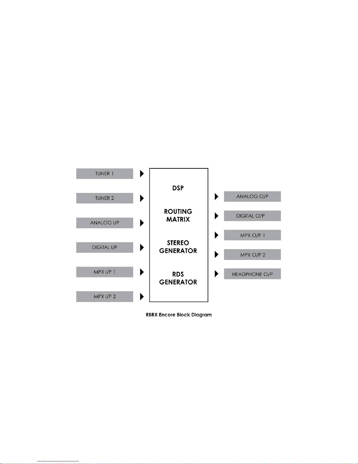
Routing & Block Diagram 11
Please see below for an audio, RF and RDS data routing diagram.
This can help you understand the enormous capabilities of the Encore family of
products!
Page 43

11 - 2
!
!
Page 44

12 - 1
Technical Specification 12
Encore family specifications. Certain parameters are irrelevant in some products.
TUNER (Dual)
Inputs 2 x 50 ohm, BNC female
Tuning range 65-108MHz in 50kHz or 100kHz steps
IF bandwidth 56kHz - 311kHz dynamic or fixed
De-emphasis 75µs, 50µs or Off
SNR (Mono/Stereo) -79dB / -60dB
THD (Mono/ Stereo) 0.011% / 0.16%
Stereo Separation >50dB
Adjacent / alternate channel rejection 70dB / 74dB
RF input level RF 0.5V to 2V
ANALOG INPUT
Nom. input level +4 dBµ
Max input level +24 dBµ
Connectors XLR balanced EMI suppressed
A/D conversion 24 bit
Distortion <0.01%
ANALOG OUTPUT
Analog output 0-24 dBµ adjustable
Connectors XLR balanced EMI suppressed
D/A conversion 24 bit
Audio monitoring output on jack +12dB maximum
DIGITAL INPUT (AES/EBU)
Sampling rate 32-192 kHz (MPX over AES ready)
Connector XLR balanced EMI suppressed
Nominal input level -20 dBFS
DIGITAL OUTPUT (AES/EBU)
Sampling rate 32-192 kHz (MPX over AES ready)
Connector XLR balanced EMI suppressed
Level -32 - 0 dBFS adjustable
MPX / RDS
Output level 0 - 12 dBµ adjustable
MPX outputs 2 x BNC EMI suppressed
D/A conversion 192KHz, internally oversampled
Stereo separation >60 dB 20Hz - 15 kHz
MPX inputs 2 x BNC EMI suppressed
A/D conversion 192KHz, internally oversampled
Pilot output BNC software switched with MPX2 output
REMOTE CONTROL
Connectors Serial, USB A, USB B, RJ45
Protocols HTTP (browser, mobile, API), SNMP, TELNET, FTP, SMTP,
RS232
PHYSICAL
Power 90-260vAC, 50/60Hz, 25w IEC connector.
Size (inch) 19W x 1.73H x 9.84D
Size (mm) 482W x 44H x 200D
Weight 1.6kg
Page 45

12 - 2
This manual was written by Andy Linton. © BW Broadcast Ltd. 2017. E&OE.
Encore products are manufactured in the UK by BW Broadcast Ltd. IO Centre, Croydon Road,
Croydon, CR0 4WQ, UK. Tel: +44 208 253 0290. US toll-free: 1-866 376 1612.
Email: support@bwbroadcast.com
‘Encore’ is a trademark of BW Broadcast Ltd.
 Loading...