


1473 T
Table of contents
 Loading...
Bush 1473 T, 1435, CTV 3459, 1434, 1474 T Manual
...
BUSH 1433
General Information
Also Covers
Bush 1434, 1435, 1473 T, 1474 T, 1435 GTV
Alba CTV 3409, CTV 3459
Goodmans GTV 3409, GTV 3459
11 AK08 & 11AK20 Chassis
Safety Notes
DO NOT CHANGE ANY MODULE UNLESS
THE SET IS SWITCH OFF.
The mains supply side of the switch mode
power supply transformer is live. Use an
isolating transformer. The receivers fulfill
completely the sfety requirements.
Safety precautions
Servicing of this TV should only be carried out
by a qualified person.
• Components marked with the warning symbol
on the circuit diagram are critical for safety
and must only be replaced with an identical
component.
• Power resistor and fusable resistors must be
mounted in an identical manner to the original
component.
• When servicing this TV, check that the EHT
does not exceed 26 KV.
TV set switched off:
Make short-circuit between HV-CRT clip and
CRT ground layer.
Short 0808 (150µF) before changing IC801 or
other components in primary side of SMPS.
Measurements
Voltage readings and oscilloscope traces are
measured under following conditions. Antenna
Signal 60 dBuV from colorbar generator. (100%
white, 75% color saturation)
Brightness, contrast, color set for a normal
picture. Mains supply, 220V AC, 50 Hz.
Service Adjustments
The following preset adjustment procedures are
not required during installation and should be
made, if necessary, after servicing.
WARNING
EHT SHOCK HAZARD The EHT must be safely
discharged before attemping to disconnect the
EHT lead from the tube anode.
Clip one end of a convenient lead, such as a
meter lead, to the tube earthing strap on the
tube body, fold back the suction cap and
discharge the EHT through the lead.
Press in one side of the spring clip which
protects into the tube cavity to ease removal of
the EHT connector.
IMPORTANT
Do not disturb the tube neck adjustments as
these have been set for optimum performance
during the tube manufacture.
Before attemping the following adjustments, the
receiver should be tuned with the brightness,
contrast and colour controls adjusted for the
best picture and all measurements are to be
made after a warm-up period of approximately 5
minutes, unless stated otherwise.
- 60 dBmV signal at any channel frequency
- Color bar pattern and 1 KHz sound signal
- Mains 220-240V AC, 50Hz
The adjustments should be carried out in the
following order for convenience.
SMPS SYSTEM VOLTAGE
1) Set the BCS (Brightness, Contrast, Satura-
tion) and VOL (Volume) to minimum.
2) Check the voltage at the shorted pins of
socket PL602 (TP1)
3) If necessary, adjust VR801 112 ± 0.5V
DC
(14”
and 15 models)
4) Set the BCS and VOL to normal picture and
sound
VISION DEMODULATOR AND AFC
1) Set the pattern generator for 10mV, 38.9 MHz
(B/G models) or 39.5 MHz (for I models) or
38.0 MHz (for 0/K models) RF output
2) Connect the RF output of the pattern
generator to any one input of SAW filter and
connect the other input of SAW filter to
ground through 10 nF capacitor (No antenna
input applied)
3) Check the voltage at the base of 0201 (TP2)
4) Adjust VL401 for 3.5 ± 0.1 Voc
2) PICTURE GEOMETRY AND FOCUS
1) Set the pattern generator for centre-cross,
circle and cross-hatch composite pattern.
2) Adjust VR702 for vertical size, VR701 for
vertical linearity, VR401 for horizontal
centering and focus potentiometer (on EHT
transformer) for optimum focusing.
TUNER AGC
1) Check the voltage at pin lof TUNER (TP4)
2) Adjust VR402 for 1V less than maximum.
SCREEN VOLTAGE
1) Set the pattern generator for grey scale.
2) Set the BCS (Brightness, Contrast, Satura-
tion) to minumum.
3) Measure cathode voltages on the CRT base
board by using a 1/1000 probe.
4) Adjust screen pot of FBT for 175 ± 2V reading
on maximum cathode voltage.
CRT BASEBOARD:CUT-OFF VOLTAGES AND
WHITE BALANCE
1) Set the pattern generator for grey scale.
2) Set the BCS (Brightness, Contrast, Satura-
tion) to minumum.
SECAM L MODULE (L/L’ AND B/G) OR (L/L’
AND K1) (11SL02)
1) Set the pattern generator for the colour bar
pattern at system PAL B/G and at frequency
of 63.75MHz.
2) Tune the receiver for the best picture.
3) Switch pattern generator to system SECAM L
and the receiver to SYS2 mode.
4) Connect the frequency counter to pin 13 of
IC101.
5) Adjust VL101 for 72.3MHz reading and
VR101 for no interference on the screen.
MAIN PCB FAULT FINDING GUIDE
AT FIRST CHECK ALL THE SUPPLY VOLTAGES, THEN CHECK FOLLOWING RELEVANT
POINTS FOR TROUBLE SHOOT!NG. TROUBLES SHOULD BE THE SAME AT ALL CHANNELS.
TROUBLE CHECK POINTS
NO PICTURE, N0 SOUND.............................................. TUNER VOLTAGES, INPUT/OUTPUT SIGNALS OK Q401, 1C401
NO PICTURE, SOUND OK ............................................. INT CVBS IN, IC401, SCREEN VOLTAGE
NO COLOUR ................................................................... IC401, IC402, IC403, X401
NO VERTICAL DEFLECTION......................................... 26 V, R711., PL701, IC701
VERTICAL LINEARITY.................................................... C705, VR701
VERTICAL SIZE .............................................................. R704, VR702
VERTICAL SHIFT ............................................................ VR703
VERTICAL FOLD............................................................. 26V, R711
HORIZONTAL LINEARITY .............................................. L601, C606
HORIZONTAL SIZE ......................................................... C603, SYSTEM VOLTAGE (112V)
HORIZONTAL FOLD ....................................................... SYSTEM VOLTAGE (112V)
FLUE PICTURE ............................................................... TR602, G3 (FOCUS), EHT, FLAMENT VOLTAGE
DARK PICTURE .............................................................. TR602 G2 (FOCUS), BRIGNES, CONTRAST VOLTAGE
NOISY PICTURE ............................................................. AGC V O LTAGE, RF SIGNAL
VERTICAL/HORIZONTAL SYNC. ................................... IC401
INTERFERENCE ............................................................. TUNER (TU201)
NO SOUND ...................................................................... R303, IC401. (PIN5), IC301
LOW SOUND ................................................................... IC401 (PIN5, SOUND CONTROL VOLTAGE), R303, IC301
SOUND DISTORTION..................................................... R303, IC301., 26V
POP NOISE ..................................................................... Q301, C307
CONTRAST ..................................................................... IC401 (PIN25)
BRIGHTNESS.................................................................. IC401 (PIN17)
COLOUR .......................................................................... IC401 (PIN26)
AUTO TUNING ................................................................ Q501
MEMORY ......................................................................... IC502
BAND SELECT ................................................................ IC503
NO VIDEO AT SCART ..................................................... SET AV MODE, CHECK IC401 (PIN5), (PIN6)
NO SOUND AT SCART ................................................... IC401 (PIN6)
MISSING CHARACTER AT TELETEXT ......................... SIGNAL AT PIN8 OF IC101
REMOTE CONTROL ....................................................... BATTERY, IR DIODE, CURRENT PATH OF IR DIODE
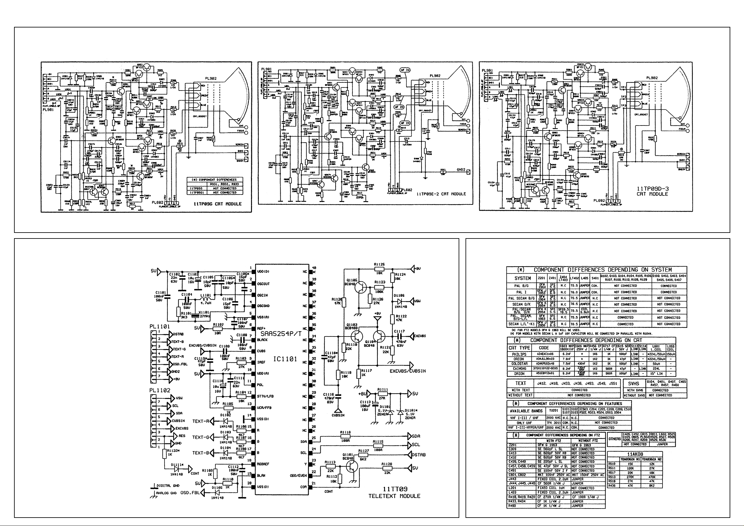
11TP09D-2 CRT MODULE COMPONENT USED FOR 14-15” CRT MODELS
PL902 3862021300 SOCKET CRT (MINI NECK)
COMPONENT DIFFERENCES DEPENDING ON CRT TYPES
COMPONENTS USED WITH 14” PHILIPS A34EAC01X06 CRTS
C603 3036227078 CAP MKP 6.2NF 1.6KV 3.5%
C606 3033344038 CAP MKP 330NF 400V J
C615 3051010832 SER 100PF 50V J
R456 3311620437 RES CF 1.6K 0W25 J
R717 3311020437 RES CF 1K 0W25 J
L601 4091411110 LINEARTY COIL 224L/150uH
4013150017 LOSS COIL 150uH
COMPONENT USED WITH 14” ORION A34JLL90X23 (W) CRTS
C603 3032827078 CAP MKP 7.8NF 1.6KV 3.5%
C606 3033344038 CAP MKP 430NF 400V J
C615 3054700836 CAP SER 47PF 50V J
R456 3311220437 RES CF 1K2 0W25 J
R717 3311020437 RES CF 1K 0W25 J
L601 4091411110 LINEARiTE COIL 224/50uH
COMPONENT USED WITH 14” GOLDSTAR A34KPU02XX46 CRTS
C603 3037527038 CAP MKP 7.5NF 1.6KV 3.5%
C606 3034341538 CAP MKP 430NF 250V J
C615 3051010832 CAP SER 100PF 50V J
R456 3311220437 RES CF 1K2 0W25 J
R717 3311020437 RES CF 1K 0W25 J
L601 4090109000 LINEARTY COIL 50uH
COMPONENT USED WITH 15” ORION A36JSW90X01 CRTS
C603 3036227038 CAP MKP 6.2NF 1.6KV 3.5%
C606 3033344038 CAP EL 330NF 400V J
C615 3051010832 CAP SER 100PF 50V J
R456 3311620437 RES CF 1.6K 0W25 J
R717 3315610437 RES CF 560R 0W25 J
L601 4091611100 LINEARITE COIL 15” LIN
11TP09G CRT MODULE COMPONENT USED FOR 14” CRT MODEL
PL902 3862021010 SOCKET CRT (NARROW NECK)
COMPONENT USED WITH 14” CAIHONG 37SX11OY22-DC05 CRTS
C603 3038227038 CAP MKP 8.2NF 1.6KV 3.5%
C606 3033344038 CAP EL 330NF 400V J
C615 3054700836 CAP SER 47PF 50V J
C901 3056810030 CAP SMD 680PF 50V J
C903 3055610030 CAP SMD 560PF 50V J
C905 3051020030 CAP SMD 1NF 50V J
C910 3051020030 CAP SMD 1NF 50V J
C911 3051020030 CAP SMD 1NF 50V J
C912 3051020030 CAP SMD 1NF 50V J
C913 NOT CONNECTED
C914 NOT CONNECTED
C915 NOT CONNECTED
C916 3052210030 CAP SMD 220PF 50V J
C917 3052210030 CAP SMD 220PF 50V J
C918 3052210030 CAP SMD 220PF 50V J
R456 3311220437 RES CF 1.2K 0W25 J
R717 RES CF 1K 0W25 J
R902 3311510830 RES SMD 150R 1/8W J
R909 3311510830 RES SMD 150R 1/8W J
R916 3311510830 RES SMD 150R 1/8W J
R907 3351032137 RES MO 10K 2W J
R914 3351032137 RES MO 10K 2W J
R915 3353993137 RES MO 3.9R 3W J
R921 3351032137 RES MO 10K 2W J
R922 3311510830 RES SMD 150R 1/8W J
R923 3313320830 RES SMD 3K3 1/8W J
R926 3313300830 RES SMD 33R 1/8W J
R931 NOT CONNECTED
R932 NOT CONNECTED
R933 NOT CONNECTED
L601 4090109000 LINEARITE COIL 224/50UH
4031001905 LOW FOCUS FBT
CRT Differences
Item Part No. Description
CPU & Adjustments
uC (MICROCONTROLLER):
The microcontroller hardware that is member of
the ST6 family has a TV receiver control
software with menu control. It controls the
chassis through IIC bus, PWM outputs and I/O
ports. Dominant features of controller are control
of optional teletext, outputs for OSD, IR control
signal receiving, and internal EEPROM.
The controller has IIC communication port at
#40 , #41 and OSD driver (R,G,B,FBI) at # 22, #
23, # 24, # 25. PWM control outputs are tuning
# 34; vertical linearity adjustment # 1; AGC
adjustment # 2. Other control outputs are Muting
- video ident # 3; led driver # 4; system switches
# 5, # 6, # 8, # 19, # 20, # 36; tuner switches #
18, # 19 and inputs are AFC information from IF
#9; keyboard # 10, # 11, # 13, # 14; scart mode
ident (4/3-16-9) #38, #39; horizontal sync # 26;
vertical # 27; infrared #35 and reset # 33.
The uC starts system according to option diodes
configuration (D501, D503, D505, D506, D508).
The controller has also a software which is able
to control some service adjustments: R, G, B
gain; R, G cut off; vertical position; vertical
linearity; horizontal position; vertical amplitude;
AGC; language selection for teletext.
For enter to service mode followed procedure
must be act within four seconds:
1 - Press volume down button on the keyboard;
2 - Press ‘prog’ button on the R/C hand set;
3 - Press ‘- -‘ button on the R/C hand set;
4 - Press “TV” button on the R/C hand set;
Parameters can be sellected by program up and
down, parameter adjustments can be done by
volume up and down buttons. Memorizing the
adjusted parameters can be done by pressing
red button. For exit from service mode Press
“TV “ button.
BUSH 1433
CRT Differences Tables
CRT Module Diagrams
Text Module Diagram
Loading...