


8
DNAGNITAREPO,NOITALLATSNI
ROFSNOITCURTSNIECIVRES
SEIRES8V
RELIOBDERIF-LIO
gnikeesnehW.reilppusliororotcartnocgnitaehruoyllac,reliobotsriaperroecivresroF
gnitaRnonwohssarebmuNlaireSdnarebmuNledoMrelioBedivorp,reliobnonoitamrofni
.reliobehtfopotnodetacollebaL
rebmuNledoMrelioB rebmuNlaireSrelioB etaDnoitallatsnI
____-____8V_ _______6
rotcartnoCgnitaeH rebmuNenohP
sserddA
As an
ENERGY
®
Partner,
STAR
Burnham Hydronics
has determined that the
V83S, V83WM, V84S,
V84WM, V85S, V85WM,
V86S, V86WM and V87
meet the ENERGY STAR
guidelines for Energy
efciency established by the
United States Environmental
Protection Agency (EPA).
®
8142824R10.5-4/07
Price - $3.00

IMPORTANT INFORMATION - READ CAREFULLY
All boilers must be installed in accordance with National, State and Local Plumbing, Heating
and Electrical Codes and the regulations of the serving utilities. These Codes and Regulations
may differ from this instruction manual. Authorities having jurisdiction should be consulted
before installations are made.
In all cases, reference should be made to the following Standards:
USA BOILERS
A. Current Edition of American National Standard ANSI/NFPA 31, “Installation of Oil
Burning Equipment”, for recommended installation practices.
B. Current Edition of American National Standard ANSI/NFPA 211, “Chimneys, Fireplaces,
Vents, and Solid Fuel Burning Appliances”, For Venting requirements.
C. Current Edition of American Society of Mechanical Engineers ASME CSD-1, “Controls and
Safety Devices for Automatically Fired Boilers”, for assembly and operations of controls
and safety devices.
D. All wiring on boilers installed in the USA shall be made in accordance with the National
Electrical Code and/or Local Regulations.
CANADIAN BOILERS
A. Current Edition of Canadian Standards Association CSA B139, “Installation Code for Oil
Burning Equipment", for recommended Installation Practices.
B. All wiring on boilers installed in Canada shall be made in accordance with the Canadian
Electrical Code and/or Local Regulations.
The following terms are used throughout this manual to bring attention to the presence of
hazards of various risk levels, or to important information concerning product life.
REGNAD
suodrazahyltnenimminasetacidnI
tluserlliw,dediovatonfi,hcihwnoitautis
i
.egamadytreporp
laitnatsbusroyrujnisuoires,htaedn
.egamad
GNINRAW
suodrazahyllaitnetopasetacidnI
dluoc,dediovatonfi,hcihwnoitautis
royrujnisuoires,htaednitluser
reporplaitnatsbus
.egamadyt
NOITUAC
ECITON
.sdrazahyrujnilanosrep
ECITON
.snoitcurtsniesehthtiwecnadroccanidetarepo
suodrazahyllaitnetopasetacidnI
tluseryam,dediovatonfi,hcihwnoitautis
ytreporproyrujnironimroetaredomni
nosnoitcurtsnilaicepssetacidnI
ecnanetniamro,noitarepo,noitallatsni
otdetalertontubtnatropmierahcihw
.launamsihtfokcabehtnodetnirpsihcihwfoypoca,ytnarrawdetimilasahreliobsihT
dnadeniatniam,dellatsnineebsahreliobehtfiylnodilavsireliobsihtrofytnarrawehT
rpgnirutcafunamehtotdetubirttaebyamsnoitcesnoritsacnotsurecafruS
ehttceffatonseoddnalamronsitsurecafruS.egarotsgnirudnoitasnednocsa
reliobafoytivegnolroecnamrofrep
.
2
llewsasseco

REGNAD
rosihtfoytinicivehtnisdiuqilrosropavelbammalfrehtoroenilosagesuroerotsTONOD
.ecnailpparehtoyna
GNINRAW
ytreporpesuacnacecnanetniamroecivres,noitaretla,tnemtsujda,noitallatsnireporpmI
illawollofoteruliaF.efilfossolroyrujnilanosrep,egamad
anosrepesuacnacredro
raendetsopdnanoitidnocelbigelnierutaretildnalaunamsihtpeeK.ecnailppa
.naicinhcetecivresdnarenwoybecnereferrofecnailppa
reporpehtnisnoitcurtsn
,snoitcurtsnilladnatsrednudnadaeR.htaedroyrujnil
dedivorperahcihwslaunamsrerutcafunamtnenopmocnideniatnocesohtllagnidulcni
sihtgnicivresrogniniatniam,gnitarepo,pu-gnitrats,gnillatsnierofebecnailppaehthtiw
efasetarepootecivresdnaecnanetniamralugerseriuqerreliobsihT
.launamsihtnideniatnocsnoitcurtsni
epxenaybylnodemrofrepebtsumecivresdna,ecnanetniam,noitallatsnI
.ycnegaecivresrorellatsnielbaegdelwonkdnadelliks
ordyhfonoitallatsnidnatuoyalehtnielbaegdelwonk
.reliobynafonoitallatsnitpmetta
ievlavfeilererusserpasselnuetelpmoctonsinoitallatsnI
.sliatedrof
opserehtsitI
.detelpmocsinoitallatsniehtnehwylreporpgnitarepoeradnadellatsni
olfelbitsubmocnonoitallatsnirofelbatiussireliobsihT
.gniteprac
oD
.detalumuccasahelacsrotoosfidenaelc
.slortnocroreliobehtretlarohtiwrepmatton
mahcnoitsubmocegamadtonod,reliobsihtgninaelcnehW
ehtwolloF.yl
,decneir
snosrepylnodnasrotcartnoctnetepmocybdengisedebdluohssmetsysgnitaehllA
dluohssmetsysgnitaehcin
gnippatehtotnidellatsnis
launamsihtfosnoitceSmirTdnagnipiPeeS-noitcestnorfforenroctfelpotnodetacol
yltcerroceraslortnocllatahteesotrotcartnocgnillatsniehtfoytilibisn
noreliobllatsnitonoD.gniro
.nosaesgnitaehehtfotratsehttaylbareferp-raeyaecnotsaeltasyaweulftcepsnI
ebdluohssyaweulfreliobdnametsystneveht,rebmahcnoitsubmocehtfoedisniehT
tegratraerro/dnarenilreb
.yletaidemmidecalperebtsumnoitalusnirebmahcnoitsubmoc,degamadfI.llaw
ebyamsaroraeyaecnotsaeltadekcehcebtsumslortnoCdnarenruBliO
.detatissecen
oslortnoctnesbaroderepmujhtiwtinuetarepotonoD
nuetarepotonoD
.retaw
.ecnailppaehtybraengnikrowrognicivresnehw
.secivedytefasr
ottcejbusneebsahecivedro,tnenopmoc,hctiws,lortnocynafiti
niatnocleufehtdnanoitsubmocfostcudorp,noitcurtsnocfoslairetamecnailppA
edla,sedixonegortin,edixonomnobrac,slatemyvaeh,acilis,animula
rehtodnastcefedhtrib,recnacesuacotainrofilaCfoetatsehtotnwonkera
ro/dnasedyh
hcihwdnayrujnisuoiresrohtaedesuacnachcihwsecnatsbuslufmrahrocixotrehto
tnempiuqednasrotaripser,gnihtolcytefasreporpesusyawlA.mrahevitcudorper
3

GNINRAW
TABLE OF CONTENTS
epipynawercsnutonoD.erusserphgihrednuretawtohyrevsniatnocreliobsihT
ylevitisoptuohtiwreliobsihtfostnenopmocynatcennocsidottpmettaronsgnittif
nirussa
ihT.reliobehtfoerusserp
.loocerayehtsselnustnenopmocynahcuottonoD.gnitareposireliobeht
dnagnihtolcevitcetorpraewsyawlA.erusserponsahdnaloocsiretawehtg
.seirujnidlacstneverpotreliobsihtgnicivresropugnitrats,gnillatsninehwtnempiuqe
dnaerutarepmetehtenimretedotseguagerutarepmetdnaerusserpehtnoylertonoD
nehwtohyrevemocebhcihwstnenopmocsniatnocreliobs
sihtfI.yrujnignidlacsfoksirehtesaercniserutarepmetretawhgiH
awcitsemodrofretaehsselknatahtiw
mirTdnagnipiPeeS.gnipipretaehsselknatniylreporpdellatsniebtsumevlav
liatedroflaunamsihtfosnoitceS
.s
poefasrofriahserfsdeenreliobsihT
.rianoitalitnevdnanoitsubmocetauqedarofsnoisivorp
nwollaotyrassecensieulfyenmihcdetcurtsbonudnanaelcA
.ycneiciffes'reliob
reliobsihT
orpparo;rehtaewdlocnidednettanutfelebtondluohsmetsys
.evitareponi
eraerehtosdellatsniebtsumdnanoitare
deppiuqesireliob
gniximcitamotuadnarotalugerwolfa,ylppusret
nimetsystnevdevorppanaotdetcennocdnadetnevylreporpebtsumecnailppasihT
.me
tsystnevdevorppanafoecnesbaehthtiwreliobetarepotonoD.noitidnocdoog
dluoctahtsemufsuoixo
ehtgniniatniamdrawotetubirtnoclliwdnaylefastnevotefilfossolroyrujniesuac
tondnanwodtuhsotreliobehtesuacyamhcihwslortnochtiwdeilppussi
gnitaeheht,ytilibissopasisepipnezorfoteudegamadfI.ecivrestuohtiwtrats-er
dnasdraugefasetairp
sireliobehtfiegamadtneverpotmetsysgnitaehehtnodellatsniebdluohssmrala
esacknarc,enilosagesutonoD.ylnolioleuf2.oNnrubotdengisedsireliobsihT
.
reliobsihtnirepaproegabragnrubreveN.enilosaggniniatnoclioynaro,sgniniard
leufsuoesagynaottrevnoctonoD.)laoc,doow.e.i(leufdilosynaottrevnoctonoD
ebdluohs,.cte,sparcsdoow,repap,sgar,sirbedelbammalfllA.)PL,saglarutan.e.i(
.sdrazaheriffoeerfdnanaelcaerareliobehtpeeK.semitllatareliobehtforaelctpek
.detelpmocsiecivresnehw
TABLE OF CONTENTS
I. Pre-Installation .........................................10
II. Knockdown Boiler Assembly ....................12
III. Packaged Boiler Assembly .........................26
IV. Water Boiler Piping & Trim ......................31
V. Steam Boiler Piping & Trim ......................36
VI. Tankless & Indirect Water Heater Piping ..38
VII. Venting & Air Intake Piping .....................41
VIII. Electrical ...................................................44
4
wdrazahlaitnetopaevahroodgniwsrenrubhtiwdeppiuqesreliobllA
derongifihcih
gninepoerofeB.efilfossolroyrujnilanosrep,egamadytreporperevesesuacnac
renrubfogniriflatnediccatneverpotreliobothctiwsecivresffonrut,roodgniws
yletelpmocrenetsafroodgniwsnethgitoteruseB.rebmahcnoitsubmocehtedistuo
IX. Oil Piping .................................................63
X. System Start-Up ........................................65
XI. Maintenance & Service Instruction ...........74
XII. Boiler Cleaning .........................................78
XIII. Trouble Shooting ......................................80
XIV. Repair Parts ...............................................81
XV Appendix
Low Water Cut Off ....................................97

TABLE 1A: DIMENSIONAL DATA (SEE FIGURES 1A THRU 1D)
Boiler
Model No.
Dimensions
See Figures 1A - 1D
Water Content - Gallons
Heat Transfer
Surface Area
- Sq. Ft.
Approximate
Shipping Weight
(LB.)
"A"
"B"
"C"
Steam
Boiler
Water
Boiler
Steam Boiler
V82
12-1/8"
6-5/8"
5"
10.0
450
V83
17-1/8"
9-1/8"
6"
10.3
12.8
15.88
542
V84
22-1/8"
11-5/8"
6"
12.4
15.7
22.92
634
V85
27-1/8"
14-1/8"
7"
14.6
18.5
29.96
726
V86
32-1/8"
16-5/8"
7"
16.7
21.4
37.00
818
V87
37-1/8"
19-1/8"
8"
18.8
24.2
44.04
910
V88
42-1/8"
21-5/8"
8"
20.9
27.1
51.08
1002
V89
47-1/8"
24-1/8"
8"
23.0
30.0
58.12
1094
NOTE: 1
The V82 Boiler is available as a packaged water boiler only.
22Maximum working Pressure: Steam: 15 PSI; Water: 30 PSI Shipped From Factory (Std.),
40 PSI Optional, 50 PSI Optional
Boiler
Model No.
*
Burner Capacity
I=B=R NET Ratings
Minimum Chmney
Requirements
AFUE %
GPH
MBH
DOE Heating
Capacity MBH
Water
MBH
Steam
MBH
Steam
Sq. Ft.
Round
In. Dia.
Rectangle
In. x In.
Height
Ft.
Steam
Water
V82W
0.60
70
61
6
8 x 8
15
82.1
V83W
1.05
147
123
107
6
8 x 8
15
82.6
V83S
V83WM
0.75
105
91
79
68
283
6
8 x 8
15
85.1
86.0
V84W
1.35
189
159
138
7
8 x 8
15
83.2
V84S
V84WM
1.05
147
127
110
95
396
6
8 x 8
15
85.3
86.1
V85W
1.65
231
196
170
7
8 x 8
15
83.9
V85S
V85WM
1.35
189
164
143
123
512
7
8 x 8
15
85.4
86.2
V86W
1.90
266
227
197
8
8 x 8
15
84.6
V86S
V86WM
1.65
231
201
175
151
629
7
8 x 8
15
85.7
86.3
V87S
V87W
2.10
294
252
219
189
787
8
8 x 8
15
84.7
85.0
V88S
2.35
329
266
200
833
8
8 x 12
15
V88W
2.35
329
275
239
8
8 x 12
15
V89S
2.60
364
298
224
933
9
8 x 12
15
V89W
2.60
364
299
260
9
8 x 12
15
*
Boiler Model Suffi x: S=Steam at standard rate, W=Water, WM=Water at minimum rate
Dimensions
Boiler
Model No.
V82
V83
V84
V85
V86
V87
V88
V89
NOTE: 1
See Figures 1A - 1D
"A"
12-1/8"
17-1/8"
22-1/8"
27-1/8"
32-1/8"
37-1/8"
42-1/8"
47-1/8"
The V82 Boiler is available as a packaged water boiler only.
Maximum working Pressure: Steam: 15 PSI; Water: 30 PSI Shipped From Factory (Std.),
40 PSI Optional, 50 PSI Optional
"B"
6-5/8"
9-1/8"
11-5/8"
14-1/8"
16-5/8"
19-1/8"
21-5/8"
24-1/8"
"C"
5"
6"
6"
7"
7"
8"
8"
8"
Water Content - Gallons
Steam
Boiler
10.3
12.4
14.6
16.7
18.8
20.9
23.0
Water
Boiler
10.0
12.8
15.7
18.5
21.4
24.2
27.1
30.0
Heat Transfer
Surface Area
- Sq. Ft.
Steam Boiler
15.88
22.92
29.96
37.00
44.04
51.08
58.12
Approximate
Shipping Weight
(LB.)
450
542
634
726
818
910
1002
1094
TABLE 1B: RATING DATA
Minimum Chmney
Burner Capacity
Boiler
Model No.
*
V82W
V83W
V83S
V83WM
V84W
V84S
V84WM
V85W
V85S
V85WM
V86W
V86S
V86WM
V87S
V87W
V88S
V88W
V89S
V89W
*
Boiler Model Suffi x: S=Steam at standard rate, W=Water, WM=Water at minimum rate
GPH
0.608484
1.05
0.75
1.35
1.05
1.65
1.35
1.90
1.65
2.10
2.35
2.35
2.60
2.60
MBH
147
105
189
147
231
189
266
231
294
329
329
364
364
DOE Heating
Capacity MBH
70
123
91
159
127
196
164
227
201
252
266
275
298
299
I=B=R NET Ratings
Water
MBH
107
138
110
170
143
197
175
219
239
260
61
79
Steam
MBH
68
95
123
151
189
200
224
Steam
Sq. Ft.
283
396
512
629
787
833
933
Requirements
Round
In. Dia.
6
6
6
7
6
7
7
8
7
8
8
8
9
9
Rectangle
In. x In.
8 x 8
8 x 8
8 x 8
8 x 8
8 x 8
8 x 8
8 x 8
8 x 8
8 x 8
8 x 8
8 x 12
8 x 12
8 x 12
8 x 12
Height
Ft.
15
15
15
15
15
15
15
15
15
15
15
15
15
15
AFUE %
Steam
85.1
85.3
85.4
85.7
84.7
Water
82.1
82.6
86.0
83.2
86.1
83.9
86.2
84.6
86.3
85.0
5
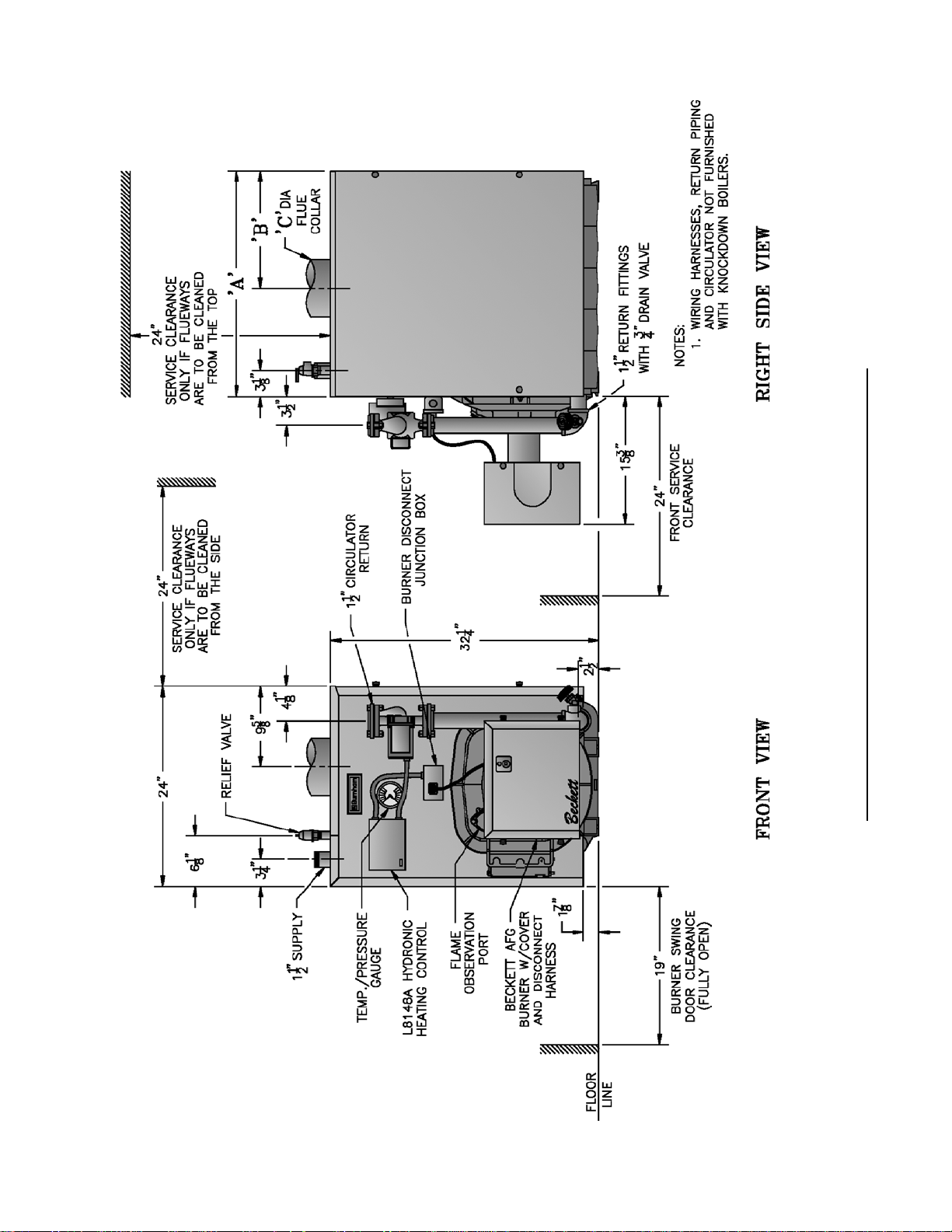
Figure 1A: V82 thru V89 Water Boiler without Tankless Heater
6
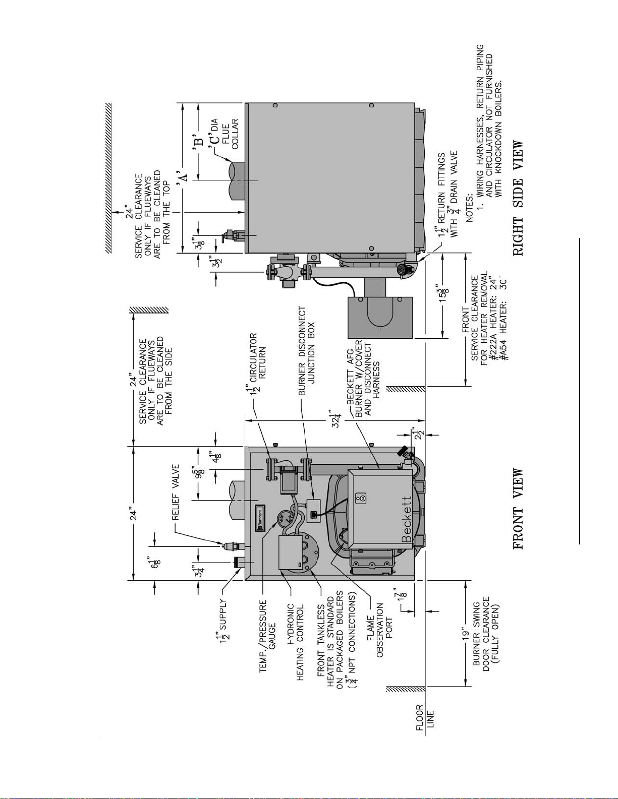
Figure 1B: V83 thru V89 Water Boiler with Front Tankless Heater
7
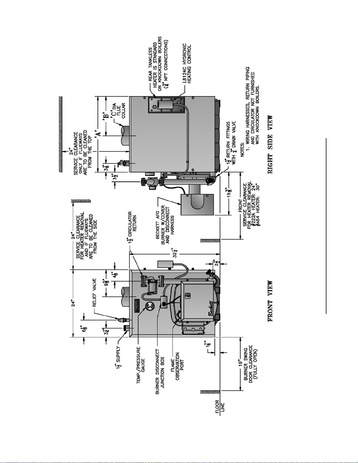
Figure 1C: V83 thru V89 Water Boiler with Rear Tankless Heater
8

Figure 1D: V83 thru V89 Steam Boiler with or without Tankless Heater
9
SECTION I: PRE-INSTALLATION
A. INSPECT SHIPMENT carefully for any signs of
damage.
1. All equipment is carefully manufactured, inspected
and packed. Our responsibility ceases upon delivery
of crated boiler to the carrier in good condition.
2. Any claims for damage or shortage in shipment
must be fi led immediately against the carrier by the
consignee. No claims for variances from, or shortage
in orders, will be allowed by the manufacturer
unless presented within sixty (60) days after receipt
of goods.
B. LOCATE BOILER in front of fi nal position before
removing crate. See Figures 1A thru 1D.
1. LOCATE so that vent pipe connection to chimney
will be short and direct.
2. BOILER IS SUITABLE FOR INSTALLATION
ON COMBUSTIBLE FLOOR. Boiler cannot be
installed on carpeting.
3. FOR BASEMENT INSTALLATION, provide
a solid elevated base, such as concrete, if fl oor is
not level, or if water may be encountered on fl oor
around boiler.
4. PROVIDE SERVICE CLEARANCE of at least
24” clearance from front jacket panel for servicing
and removal of front tankless heater (increase to
30" for #A54 heater). If boiler is equipped with
a rear tankless heater, provide at least 24" service
clearance on the right side of the boiler. Boiler
fl ueways may be cleaned either from the top or from
the right side. Provide at least 24" clearance from
either the right side of the boiler or the top of the
boiler for cleaning fl ueways.
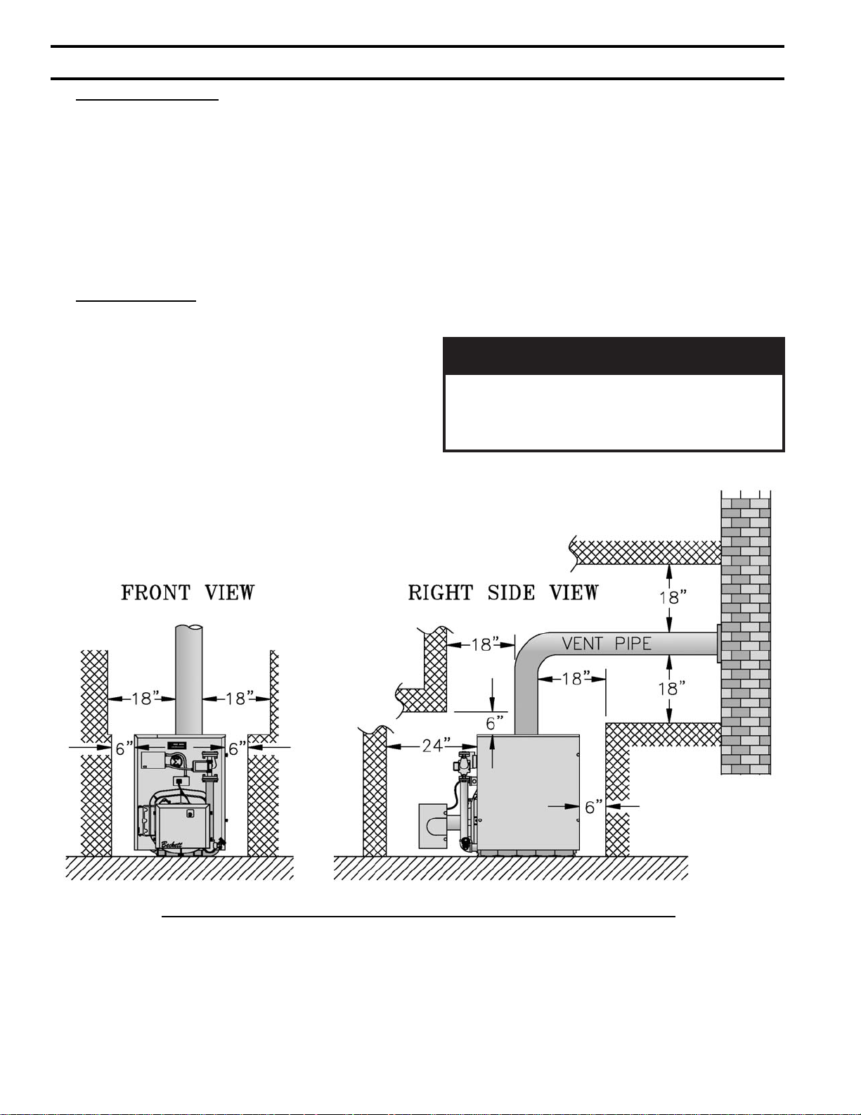
5. For minimum clearances to combustible materials.
See Figure 2.
ECITON
tnevllawelgnisrofsignitnevotecnaraelC
yamecnaraelc,desusitnevLepyTfI.epip
ehtybderiuqermuminimehtotdecudereb
.rerutcafunamepiptnev
Figure 2: Minimum Installation Clearances To Combustible Materials (Inches)
NOTES:
1. Listed clearances comply with American
National Standard ANSI/NFPA 31, Installation of
Oil Burning Equipment.
2. V8 Series boilers can be installed in rooms with
clearances from combustible material as listed
10
above. Listed clearances cannot be reduced for
alcove or closet installations.
3. For reduced clearances to combustible material,
protection must be provided as described in the
above ANSI/NFPA 31 standard.

C. PROVIDE COMBUSTION AND VENTILATION
AIR. Local and National Codes may apply and should
be referenced.
GNINRAW
noitalitnevdnanoitsubmocetauqedA
reporperussaotdedivorpebtsumria
efasniatniamotdnanoitsubmoc
etriatneibma
yhfosecruos
.derots
1. Determine volume of space (boiler room). Rooms
communicating directly with the space in which
the appliances are installed, through openings not
furnished with doors, are considered a part of the
space.
Volume(ft3) = Length(ft) x Width(ft) x Height(ft)
2. Determine total input of all appliances in the space.
Add inputs of all appliances in the space and round
the result to the nearest 1000 BTU per hour.
3. Determine type of space. Divide Volume by total
input of all appliances in space. If the result is
greater than or equal to 50 ft3/1000 BTU per hour,
then it is considered an unconfi ned space. If the
result is less than 50 ft3/1000 BTU per hour then the
space is considered a confi ned space.
4. For boiler located in an unconfi ned space of a
conventionally constructed building, the fresh
air infi ltration through cracks around windows
and doors normally provides adequate air for
combustion and ventilation.
5. For boiler located in a confi ned space or an
unconfi ned space in a building of unusually tight
construction, provide outdoor air.
a. Outdoor air for combustion may be provided
with an optional Burnham V8 Inlet Air
Accessory Kit, Part Number 611280031 (ONLY
AVAILABLE WITH BECKETT BURNER).
See Section VII for installation details.
or
.serutarepm
roenilosagerehwreliobllatsnitonoD
ro,sdiuqilrosropavelbammalfrehto
,sehcaelb.e.i(snobracord
rodesuera).cte,srenetfoscirbaf
b. Outdoor air may be provided with the use of two
permanent openings which communicate directly
or by duct with the outdoors or spaces (crawl or
attic) freely communicating with the outdoors.
Locate one opening within 12 inches of top
of space. Locate remaining opening within 12
inches of bottom of space. Minimum dimension
of air opening is 3 inches. Size each opening per
following:
i. Direct communication with outdoors.
Minimum free area of 1 square inch per
4,000 BTU per hour input of all equipment
in space.
ii. Vertical ducts. Minimum free area of 1
square inch per 4,000 BTU per hour input of
all equipment in space. Duct cross-sectional
area shall be same as opening free area.
iii. Horizontal ducts. Minimum free area of 1
square inch per 2,000 BTU per hour input of
all equipment in space. Duct cross-sectional
area shall be same as opening free area.
Alternate method for boiler located within
confi ned space. Use indoor air if two
permanent openings communicate directly
with additional space(s) of suffi cient volume
such that combined volume of all spaces
meet criteria for unconfi ned space. Size each
opening for minimum free area of 1 square
inch per 1,000 BTU per hour input of all
equipment in spaces, but not less than 100
square inches.
6. Louvers and Grilles of Ventilation Ducts
a. All outside openings should be screened and
louvered. Screens used should not be smaller
than 1/4 inch mesh. Louvers will prevent the
entrance of rain and snow.
b. Free area requirements need to consider the
blocking effect of louvers, grilles, or screens
protecting the openings. If the free area of the
louver or grille is not known, assume wood
louvers have 20-25 percent free area and metal
louvers and grilles have 60-75 percent free area.
c. Louvers and grilles must be fi xed in the open
position, or interlocked with the equipment to
open automatically during equipment operation.
11
SECTION II: KNOCKDOWN BOILER ASSEMBLY
A. REMOVAL OF BARE BOILER FROM SKID
1. Boiler is secured to skid with 4 bolts, 2 in front and
2 in rear of shipping skid, see Figure 3. Remove all
bolts.
Figure 3: Knockdown Boiler Removal from Skid
2. Tilt boiler to right and to rear. Using right rear leg
as pivot, rotate boiler 90° in a clockwise direction,
and lower left side of boiler to fl oor. Tilt boiler and
remove skid.
B. MOVE BOILER TO PERMANENT POSITION
by sliding or walking.
C. TEST BOILER FOR LEAKS before installing
controls, trim, and jacket, and before connecting to
heating system.
1. Loosen nuts on tie rods until only fi nger tight.
2. Install pressure gauge (at least 50 PSI capacity),
a hose to the city water and a valve in the supply
tapping. Plug remainder of tappings.
3. Fill boiler with water and apply a pressure of at least
10 PSI but no more than 50 PSI gauge pressure.
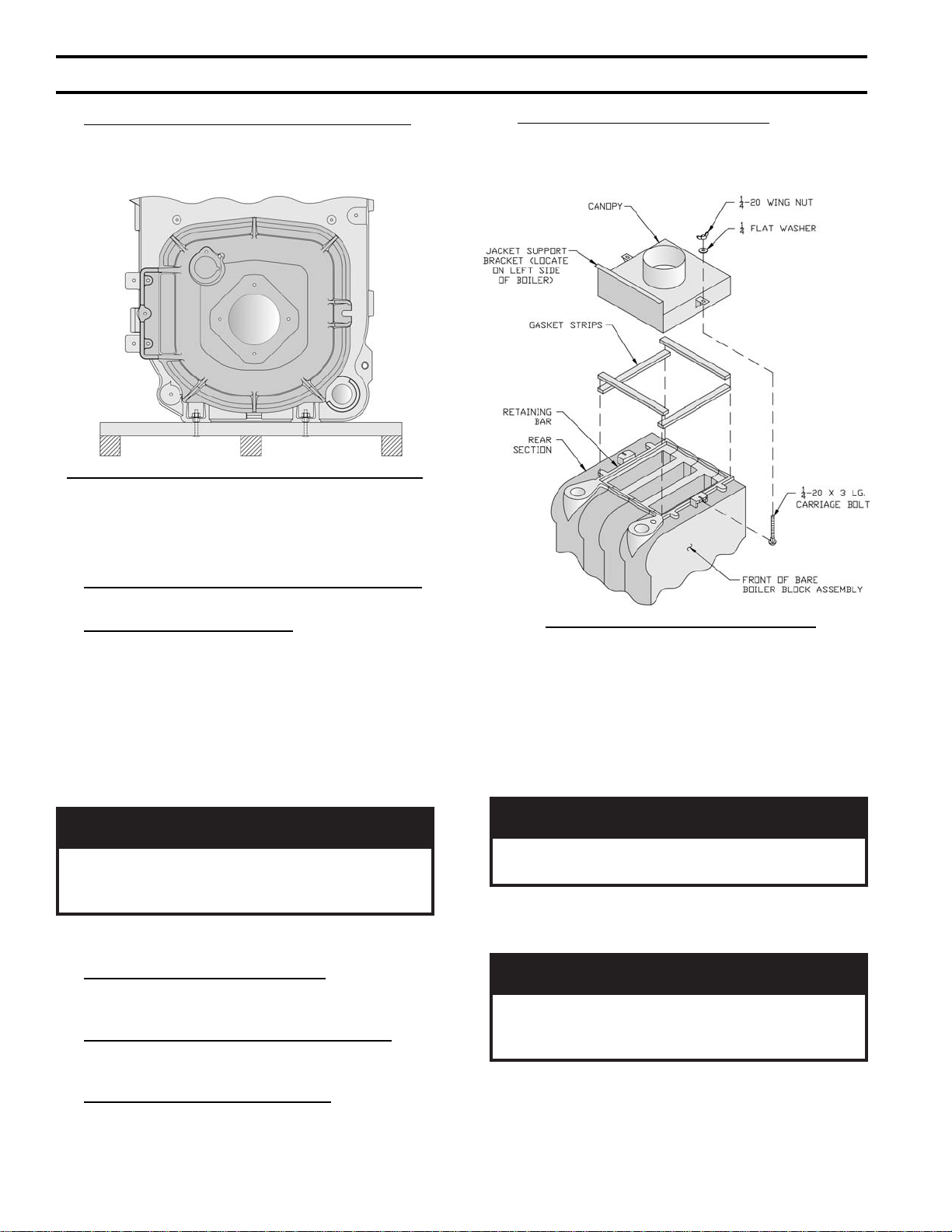
G. INSTALL AND SECURE CANOPY with gasket
and hardware provided to ensure gas tight seal — see
Figure 4.
Figure 4: Boiler Canopy Installation
1. Cut two (2) strips 13 ¾” long from the roll of gasket
insulation. Place one (1) strip across the top of the
front section and the other across the rear section as
shown in Figure 4.
2. Cut the remainder of the roll into two (2) equal
pieces. Place each piece along the sides, allowing
the ends to overlap the front and rear pieces.
GNINRAW
reliobedisnitfelriaonsierehttahterussA
roftsettonoD.skaelrofgnikcehcnehw
.riadezirusserphtiwskael
4. Examine boiler carefully inside and outside for leaks
or damage due to shipment or handling.
D. DRAIN WATER FROM BOILER. Remove gauge,
valve and plugs from those tappings to be used. Leave
other tappings plugged or bushed according to Figure 5.
E. INSPECT JOINTS BETWEEN SECTIONS. All
joints are factory sealed. If there are any spaces due to
shipment or handling, seal them with boiler putty.
F. INSPECT FLUE COVER PLATES for tightness.
If loose, retighten mounting hardware. If fl ue plate or
sealing rope is damaged, repair or replace as needed.
12
NOITUAC
ybegakcolbyaweulfynawollatonoD
.teksag
3. Position canopy body within the retaining bar which
borders the fl ueway openings on top of the bare
boiler block assembly.
ECITON
tfelgnicafebtsumtekcarbtroppustekcaJ
tonlliwtekcaJ.4erugiFees-reliobfoedis
rbfitif
4. Secure canopy to boiler with two (2) 1/4" - 20 x 3"
long carriage bolts, 1/4" fl at washers and 1/4" - 20
wing nuts provided.
.yltcerrocdetneirotonsitekca
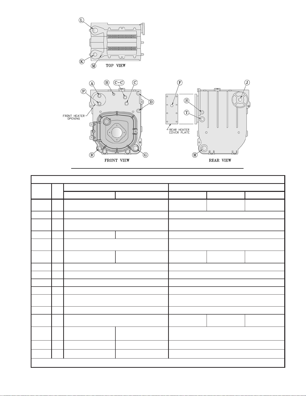
gnippaT
noitacoL
A"¾
B"¼
C"¾
C-C"¾
D"½
F"¾
G"½1
H"½1
J"½1
K"2
L"2
M"¾
P"¾
R"¾
Figure 5: Boiler Tapping Locations and Usage (Knockdown Boilers Only)
SGNIPPATFOESOPRUP
eziS
TPN
retaeH-noNretaeH/wretaeH-noNretaeHtnorFretaeH
gulPhsulFgulPhsulFA/N
A/NlortnoCgnitarepOA6004LA/NA/N
deggulP-gnippaT.xuA
)nruteRtceridnI(
relioBmaetSrelioBretaW
)OCWLeborP(timiLerusserP
)OCWLtaolF(deggulP
eguaGerusserP eguaGerusserP/erutarepmeT
.dtSOCWLeborP
)OCWLtaolF(deggulP
)OCWLeborP(ssalGeguaGretaW
nruteRdeggulP
deggulP-ffowolBecafruS gulPhsulF
)noitceS9urht3(ylppuStnorF )noitceS9urht3(ylppuStnorF
evlaVytefaS evlaVfeileR
deggulP-gnippaTyrailixuA
)taolF(OCWLdna,lorterusserP,ssalGeguaGretaW
)nruteRlanoitpO(evlaVniarDrof"¾otdehsuB nruteR
)noitceS5urht3(ylppuSdnoceSlanoitpO,deggulP
)noitceS9urht6(ylppuSdnoceSderiuqeR
deggulP-gnippaT.xuA
)nruteRtceridnI(
*
A8418L
lortnoCgnitarepO
-gnippaT.xuA
deggulP
raeR
C4218L
lortnoCgnitarepO
A/N
A/N
gulPhsulF
C4218L
lortnoCgnitarepO
)noitceS9urht3(deggulP
A/N
deggulP-gnippaTyrailixuA
-gnippaT.xuA
deggulP
*
S"½
T"1
timiLtceridnI
ylppuStceridnI
retaeHsselknaTfoueilnI
timiLtceridnI
*
ylppuStceridnI
*
A/N
A/N
13
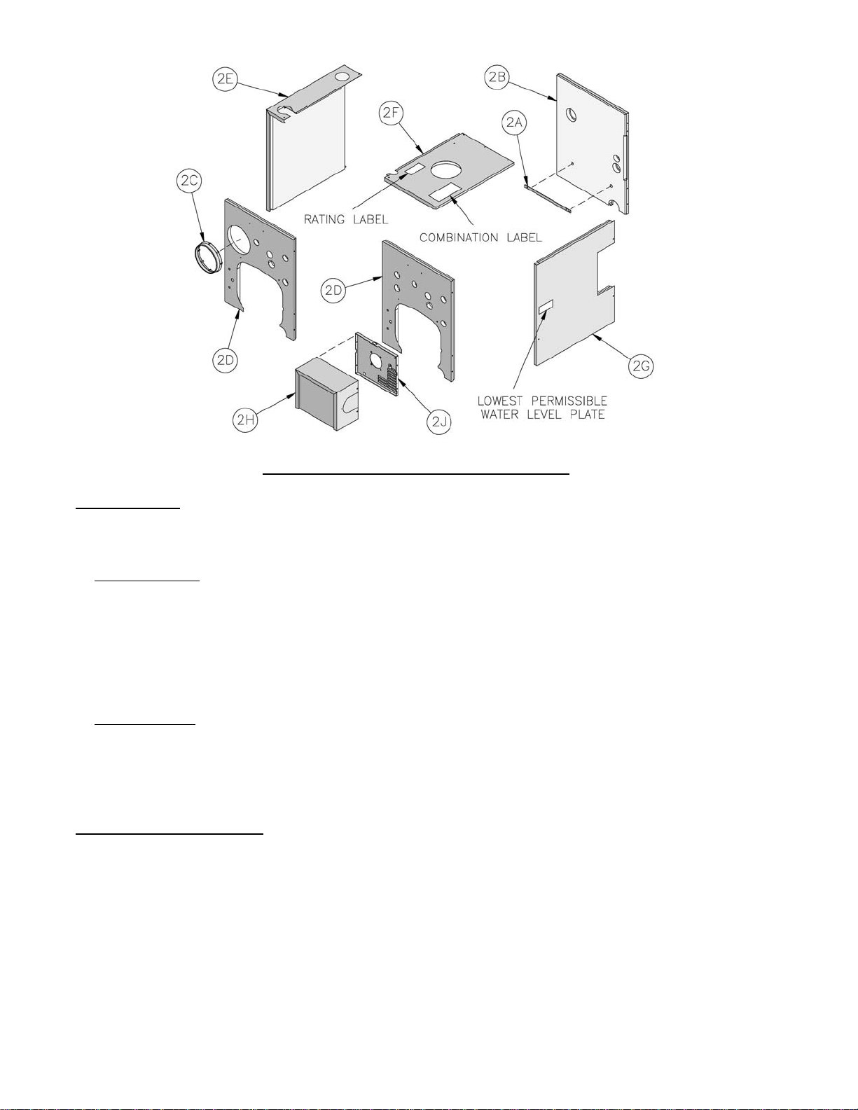
Figure 6: Knockdown Boiler Jacket Assembly
H. INST ALL TRIM. The following steam or water trim
will be concealed or inaccessible after boiler jacket is
installed, see Figure 5 for boiler tapping locations and
usage.
1. STEAM BOILER — Top tappings:
a. Tapping "L" — Install 2" NPT plug in rear
section top supply tapping on boiler sizes V83
thru V85, if only one supply riser is used.
b. Tapping “M” — Install ¾” NPT coupling and
¾” NPT x 8” long nipple into ¾” NPT tapping
located next to front section top supply tapping
— all boiler sizes.
2. WATER BOILER — Top tappings:
a. Tapping “L” — Install 2” NPT plug in rear
section top supply tapping — all boiler sizes.
b. Tapping “M” —Install ¾” NPT x 8” long nipple
into ¾” NPT tapping located next to front section
top supply tapping — all boiler sizes.
I. INSTALL BOILER JACKET. (See Figure 6).
1. Remove burner swing door and hinge assembly.
Remove one (1) 5/16"-18 fl ange nut and washer
from right side latching stud and one (1) 5/16"-
18 x 3½" cap screw on left side used for securing
burner swing door to the boiler section. Swing door
open and remove 5/16" hairpin cotter from rear
hinge pin. While holding swing door remove hinge
pin and set door aside. Remove two (2) 5/16" -
18 x ¾" long cap screws securing the hinge bracket
to the boiler section.
2. Install jacket rear panel support bracket. (See Figure
6, Item 2A). Align bracket with two (2) 5/16" - 18
tapped holes in rear section and secure with two (2)
5/16" - 18 x 1/2" long cap screws.
3. Install jacket rear panel. (See Figure 6, Item 2B).
Align holes in jacket rear panel and support bracket.
Secure with two (2) #8 x 1/2" long sheet metal
screws.
4. Jacket Front Panel
a. Install black plastic collar extension to jacket
front panels for 7-13/16" diameter tankless
heater opening. (See Figure 6, Items 2C and
2D). Engage two (2) of the collar retaining
tabs over raw edge of jacket opening. Provide
support behind the panel with one hand while
applying pressure on collar to snap each tab
over edge of opening until all eight (8) tabs are
securing collar.
b. Install jacket front panel. Locate two (2) 11/32"
diameter holes, one round, one obround, on front
panel approximately 16” up from the bottom of
the panel. Align these holes with the similarly
located 5/16" - 18 tappings on the front section.
Secure with two (2) 5/16" - 18 x 1/2" long cap
screws.
5. Install jacket left side panel. (See Figure 6, Item
2E). Fold panel at perforation keeping insulation
inward. Align left side panel mounting holes with
the front and rear panel holes. Secure with #8 x ½”
long sheet metal screws.
14
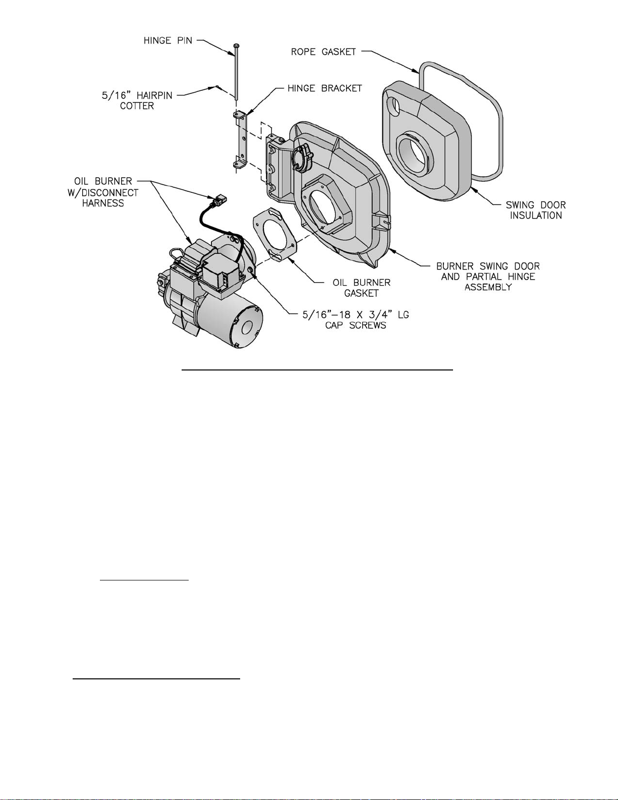
Figure 7: Oil Burner Installation (Beckett Burner Shown)
6. Install jacket top panel. (See Figure 6, Item 2F).
Place jacket top panel on boiler and secure to front,
rear and left side panels with #8 x ½” long sheet
metal screws.
7. Install jacket right side access panel. (See Figure
6, Item 2G). Align right side panel mounting holes
with front and rear panel holes. Secure with #8 x ½”
long sheet metal screws.
8. Attach the labels shipped in the instruction envelope
as follows:
a. Locate both the Rating Label and Combination
Warning Label (P/N 8142803). Remove paper
backing from the labels and apply to the jacket
top panel in approximate locations shown in
(Figure 6, Item 2F).
b. On steam boilers only; locate Lowest Permissible
Water Level Plate (Form No. 1204 shipped in
Steam Trim Carton). Align plate with two 1/8"
diameter holes located near the front edge; in
line with the lower sight glass tapping, of the
jacket right side access panel. Attach plate with
two (2) #8 x 1/2" long sheet metal screws. (See
Figure 6, Item 2G).
J. INSTALL BECKETT OIL BURNER. (See Figure
7).
1. Check target wall and combustion chamber blanket.
If any damage or movement occurred during
shipment, replace as needed.
2. Locate burner swing door and hinge assembly
removed in Paragraph I, No. 1. Check the burner
swing door insulation and rope gasket for damage
and adhesion. If damaged, replace insulation or
gasket. If insulation or gasket is loose, reattach to
swing door with RTV 732 or 736 silicone caulk.
3. Install burner swing door in reverse order from
Paragraph I, No. 1.
4. Use the following procedure to properly close
and secure the burner swing door after it has been
removed and re-installed for Field Assembly
(Knockdown Boiler) or opened for inspection,
cleaning or fi eld service (refer to Figures 11A and
11B):
Step 1. Lift the door up unto the built-in cast ramp/
door rest (protruding from the bottom of the front
section casting - see Figure 11A), while rotating
the articulated hinge and door to the right and
engaging the slot (on right side of door) unto the
5/16" stud protruding from the front section.
Step 2. Use one hand to help hold door in position
by applying pressure directly to the door while
re-installing the securing hardware with your
opposite hand. Always install right side
latching hardware (5/16" fl ange nut and
fl at washer) fi rst, then install left side hinge
hardware (5/16" x 3-1/2" lg. hex head fl ange
bolt) second. Apply additional pressure while
hand tightening the hardware as far as possible,
then release the pressure.
15

ECITON
ekamroodgniwsrenrubgnirucesnehW
Step 3. Use a hand wrench to tighten door hardware
and always start with the right side fl ange
nut fi rst (see fi gure 11B). Use an alternating
tightening method from right side fl ange nut
to left side fl ange bolt to tighten door equally
until sealed without applying excessive torque.
Never tighten left side fl ange bolt fi rst or tighten
either piece of hardware 100% without using the
alternating tightening method described above.
5. Place oil burner gasket on burner and align holes.
NOITUAC
.teksagtuohtiwrenrubllatsnitonoD
6. Insert oil burner into the opening of the burner
swing door. Align holes and install four (4) 5/16”
- 18 x ¾” long cap screws. Level burner and fully
tighten all four (4) screws.
7. Install oil nozzle in burner, inspect electrodes and
head setting.
REGNAD
elzzonlionaevahtonseodrenrubehT
deilppus,elzzonlioreporpehT.dellatsni
elzzonehtnidellatsniebtsum,esool
httuohtiwrenrubetarepotonoD.rotpada
.renrubehtnidellatsnielzzonlioreporp
e. Remove nozzle line electrode assembly.
f. Remove Beckett MD(V1) or MB(L1) Head.
g. Remove plug from nozzle adapter and install
.sedishtobnoyllauqeni-nwardsirooderus
K. INSTALL CARLIN 102CRD OIL BURNER. (See
e
the proper nozzle. Refer to Table 6 for proper
nozzle. The nozzle must be securely installed
to assure leak free joints between the nozzle and
adapter. When installing the nozzle, be careful
not to bump or move the burner electrodes.
h. Inspect and measure burner electrodes. Refer
to Figure 27A for the proper electrode setting.
Readjust electrode setting to the proper
dimensions if necessary.
i. Reinstall Beckett MD(V1) or MB(L1) Head.
j. Reinstall nozzle line electrode assembly.
k. Connect copper connector tube.
l. Inspect Beckett head setting on left side of
burner by insuring the blue line MD(V1) or the
line on the label MB(L1) are aligned, readjust if
necessary.
m. Tighten knurled nut.
n. Swing igniter closed, rotate tabs and tighten two
(2) igniter screws.
o. Replace burner cover and tighten burner cover
knobs.
Figure 7).
Follow instructions in Paragraph J, Steps 1 through 6.
7. Install oil nozzle in burner, inspect electrodes and
head setting.
REGNAD
16
a. Select the proper oil nozzle for the installation.
Two (2) oil nozzles are supplied loose with each
knockdown V83 - V86 boiler. Either nozzle may
be used with water boilers. Steam boilers must
use the lower input nozzle. The lower input
nozzle will provide greater boiler effi ciency
and for steam boilers, reduce boiler corrosion.
However, boiler output will be reduced. Refer
to Table 1B for ratings. The nozzle input is
stamped on the hex fl at of the nozzle.
NOITUAC
ehttadetarepoebylnotsumsreliobmaetS
etargnirifehtgnisaercnI.tupnirewol
detareleccanitluserlliwtupnisihtevoba
ytnarrawehtdiovlliwdnanoisorrocreliob
.reliobehthtiwdedivorp
b. Loosen burner cover knobs and remove cover.
c. Loosen two (2) igniter latching screws, rotate
tabs and swing open igniter about hinge.
d. Loosen knurled nut and disconnect copper
connector tube.
elzzonlionaevahtonseodrenrubehT
deilppus,elzzonlioreporpehT.dellatsni
elzzonehtnidellatsniebtsum,esool
e
httuohtiwrenrubetarepotonoD.rotpada
.renrubehtnidellatsnielzzonlioreporp
NOITUAC
ehttadetarepoebylnotsumsreliobmaetS
etargnirifehtgnisaercnI.tupnirewol
detareleccanitluserlliwtupnisihtevoba
ytnarrawehtdiovlliwdnanoisorrocreliob
.reliobehthtiwdedivorp
Steam Boilers Only
Knockdown V87 - V89 boilers are provided with
one nozzle, installed in the burner, that provides
the same fi ring rate as the water boiler of the
same size.
a. Installation/Removal of Drawer Assembly
i. Loosen screws, rotate latches and swing
open the transformer.
Disconnect the fl ared fi tting to the oil line
and remove the aluminum thumb-nut from
the nozzle line. Remove the combustion
head assembly from the air tube. Rotating
the assembly upside down will ease
removal. Inspect the nozzle for size and
type, refer to Table 6 of this manual.
ii. To change a nozzle, loosen the clamp screw
on the retention ring assembly and slide the
retention ring off the adaptor.
Install and tighten the proper nozzle in
the adaptor. See Table 6 of this manual.
Be careful not to damage the electrode
insulators or to bend the wires.
iii. Replace the retention ring assembly, slipping
one of the riveted arms through the 1/8-inch
gap between the electrode tips. This arm
should be straight up. Also, be sure that the
retention ring clamp is tight against the
shoulder on the adaptor. Then tighten the
clamping screw.
iv. Check the electrode settings specifi ed as
follows and shown in Figure 27B. 1/8-inch
gap, 1/4-inch above the nozzle centerline,
and 3/16-inch ahead of the nozzle tip.
v. Re-install the combustion head assembly
into the air tube. It may be necessary to turn
nozzle line assembly upside down to ease
insertion into the air tube. Then the threaded
adapter on the end of the nozzle line is
passed through the opening in the left side of
the housing.
vi. Run the aluminum (knurled) thumb-nut onto
the nozzle line and tighten hand-tight.
vii. Connect the fl ared fi tting on the copper oil
line to the nozzle line and tighten.
viii. Swing the transformer to the closed position,
rotate latches and tighten screws.
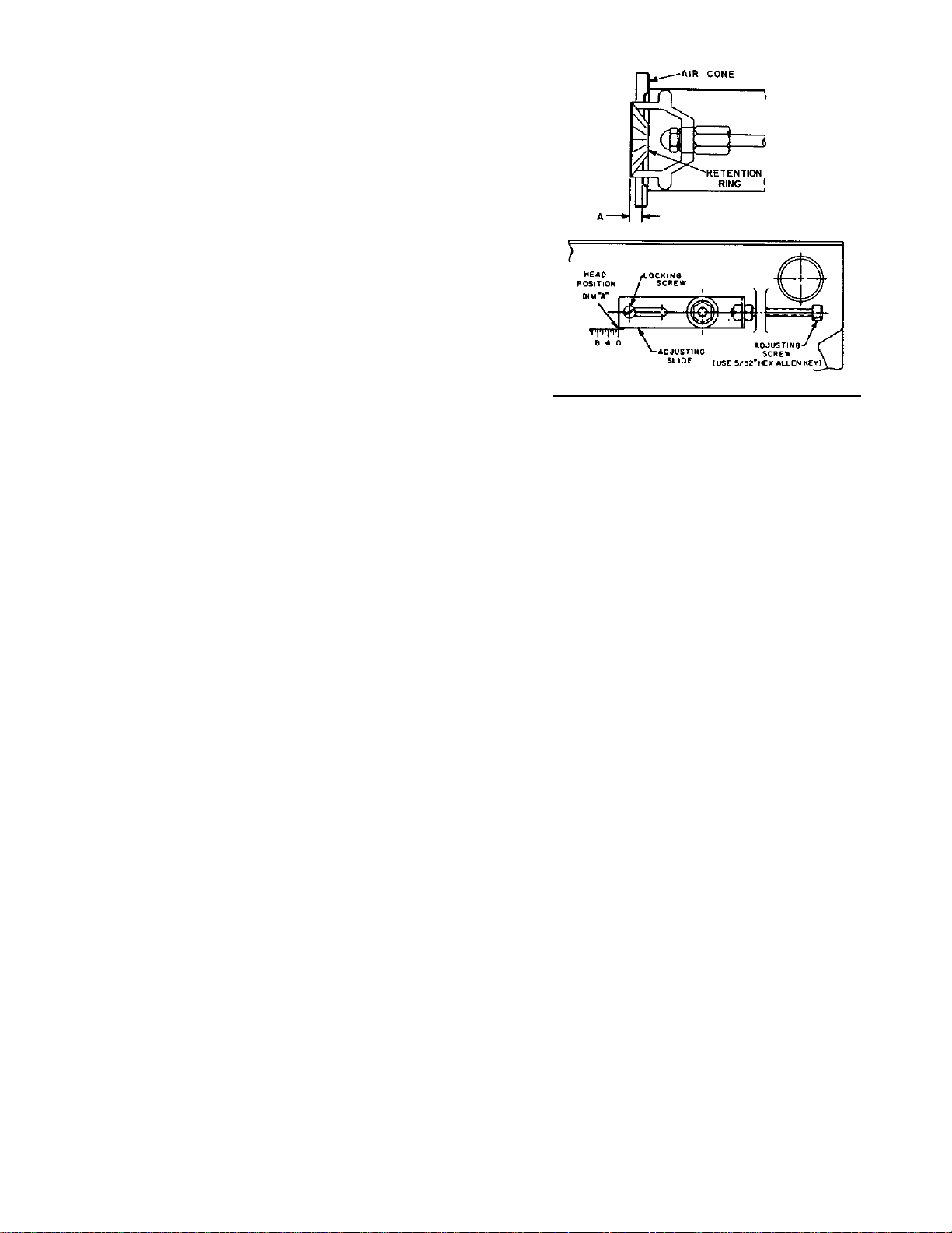
b. Combustion Head Setting/Adjustment
i. Verify combustion head setting, refer to
Table 6 of this supplement. Read the scale
embossed in the housing, which is calibrated
in 1/16-inch divisions (dimension ‘A’)
the position of the fl ame retention ring in
relation to the air cone can be determined at
a glance. Refer to Figure X.
ii. By moving the electrode and combustion
head assembly forward or backward, the
location of the fl ame retention ring relative
to the throttle ring can be controlled. Refer
to Figure 7A.
By loosening the locking screw and thumb-
nut and turning the adjusting screw using a
5/32-inch allen wrench, the assembly can be
Figure 7A: Combustion Head Adjustment
moved to the required position.
Turn the adjusting crew clockwise to move
the combustion head forward, increasing the
‘A’ dimension, counterclockwise will pull
the head back, decreasing the ‘A dimension.
To lock in place, fi rst tighten the thumb-nut
and then the locking screw.
c. Initial Air Shutter/Band Setting
i. The air shutter has a pointer which indicated
the percent of opening against a calibrated
scale (9 = 90%, fully open = 100%). The
setting is locked in place by a screw just
above the fuel unit.
ii. The air band is adjusted by loosening the
screw, rotating the air band and then locked
in place after fi nal adjustment. Refer to
Table 6 of this manual for initial settings.
iii. The burner is now set at the approximate
air band setting for the gallonage indicated.
During fi nal adjustment, using combustion
testing equipment, the air band may need
minor adjustment to achieve the desired
effi ciency.
Water Boilers Only
Knockdown V87 - V89 boilers are provided
with one nozzle, installed in the burner, that
provides the same fi ring rate as the steam
boiler of the same size.
Inspect the installed nozzle and assure that
the nozzle is the correct size and type as
specifi ed in Table 6 of this manual. The
nozzle input is stamped on the hex fl at of the
nozzle.
Refer to Paragraph K, 7, a for burner drawer
assembly removal.
17

L. INSTALL CARLIN ELITE EZ OIL BURNER.
(See Figure 7).
Follow instructions in Paragraph J, Steps 1 through 6.
7. Inspect oil nozzle, electrodes and head setting/
change fi ring rate.
REGNAD
elzzonlionaevahtonseodrenrubehT
deilppus,elzzonlioreporpehT.dellatsni
elzzonehtnidellatsniebtsum,esool
.renrubehtnidellatsnielzzonlioreporp
NOITUAC
etargnirifehtgnisaercnI.tupnirewol
detareleccanitluserlliwtupnisihtevoba
.reliobehthtiwdedivorp
Steam Boilers Only
Steam boilers must use the lower input nozzle.
The lower input nozzle will provide greater
boiler effi ciency and for steam boilers, reduce
boiler corrosion. However, boiler output will be
reduced.
Burners for knockdown V83 - V86 steam boilers
are shipped with the lower (standard) fi ring rate
nozzle installed. Knockdown V87 - V89 boilers
are provided with one nozzle, installed in the
burner, that provides the same fi ring rate as the
water boiler of the same size.
a. Installation/Removal of Drawer Assembly
i. Loosen screws, rotate latches and swing
open the transformer.
ii. The combustion head assembly can be
removed with the blower wheel access cover
in place or removed. If the access cover is
removed, the head assembly will not have to
be rotated.
Disconnect the fl ared fi tting to the oil line
and remove the aluminum thumb-nut from
the nozzle line. Remove the combustion
head assembly from the air tube. Rotating
the assembly upside down will ease
removal.
iii. Loosen the clamp screw on the retention
ring assembly and slide the retention ring off
the adaptor.
Install and tighten the proper nozzle in
the adaptor. See Table 6 of this manual.
Be careful not to damage the electrode
insulators or to bend the wires.
iv. Replace the retention ring assembly, slipping
one of the riveted arms through the 1/8-inch
gap between the electrode tips. This arm
should be straight up. Also, be sure that
the retention ring clamp is tight against the
shoulder on the adaptor. Then tighten the
clamping screw.
v. Check the electrode settings specifi ed as
follows and shown in Figure 27C. 1/8-inch
gap, 1/4 to 5/16-inch above the nozzle
centerline, and fl ush to 1/16-inch ahead of
ehttuohtiwrenrubetarepotonoD.rotpada
ehttadetarepoebylnotsumsreliobmaetS
ytnarrawehtdiovlliwdnanoisorrocreliob
b. Combustion Head Positioning Bars
the nozzle tip.
vi. Re-install the combustion head assembly
holding it upside down while inserting
into the housing. The fl ame retention ring
end of the assembly must be lifted and
guided through the throttle cone (a reduced
diameter) in the end of the air tube. DO
NOT FORCE IT.
vii. After attaching the proper positioning bar,
refer to Paragraph 7,b, run the thumb-nut
onto the nozzle line and tighten it lightly.
Connect the fl ared fi tting on the copper oil
line to the nozzle line and tighten.
i. The Elite EZ-1HP and EZ-2HP burners are
supplied with the proper positioning bar
installed onto the housing that matches the
high (standard) input oil nozzle installed in
the burner. A second positioning bar and
nozzle for the lower (minimum) fi ring rate
is shipped loose for the V83-V86 models,
attached the burner.
Verify that the installed positioning bar
matches the high input oil nozzle installed
in the burner or replace them both with the
nozzle and positioning bar that matches
the lower fi ring rate, refer to Table 6 of this
manual.
The remaining bar(s) should be placed in
the rear of the housing or junction box for
future use in the event the fi ring rate must be
changed.
In the case of the EZ-1HP, the proper head
positioning bar is still matched by the size
of the nozzle, not the input. For example, if
nozzle size is 0.75 GPH, input @ 150 psi is
approximately 0.90 GPH and the proper bar
is 0.75 GPH.
ii. Model EZ-1HP Positioning Bars: 0.50
GPH, 0.60-0.65 GPH, 0.75 GPH, 0.85-1.00
GPH, 1.10-1.25 GPH, 1.35-1.50 GPH, 1.65
GPH.
iii. Model EZ-2HP Positioning Bars: 1.50
GPH, 1.65-1.75 GPH, 2.00 GPH, 2.25 GPH.
18
c. Initial Air Band Setting
i. The nozzle size in GPH INPUT is printed
directly on the air band. Loosen the locking
screw, move the air band until the pointer
on the air shutter and housing lines up with
the appropriate GPH INPUT. Tighten the
locking screws.
ii. The Elite burners use calibrated air bands
marked in nozzle sizes. Models EZ-1HP
and EZ-2HP have air bands calibrated to
deliver the proper amount of air for their
specifi c pump pressure. The air bands on
H.P. models are designed to be set by the
rating stamped on the nozzle.
iii. The burner is now set at the approximate
air band setting for the gallonage indicated.
During fi nal adjustment, using combustion
testing equipment, the air band may need
minor adjustment to achieve the desired
effi ciency.
Water Boilers Only
Select the proper oil nozzle for the installation.
Burners for knockdown V8 water boilers are
shipped with the high (standard) input oil nozzle
installed in the burner.
A second oil nozzle for the lower (minimum)
fi ring rate is shipped loose for the V83 - V86
models, attached to the burner. Either nozzle
may be used with water boilers. The lower
(minimum) input nozzle will provide greater
boiler effi ciency. However, boiler output will be
reduced. Refer to Table 1B for fi ring rates. If
the higher rate is desired, inspect the installed
nozzle and assure that the nozzle is the correct
size and type as specifi ed in Table 6 of this
manual. The nozzle input is stamped on the hex
fl at of the nozzle.
If the lower (minimum) input is desired, remove
the nozzle which was factory installed. Locate
the lower (minimum) fi ring rate nozzle that is
supplied loose. Confi rm the nozzle is the proper
size and type for the lower fi ring rate as specifi ed
in Table 6 of this manual. Install the proper
nozzle in the burner nozzle adaptor.
Refer to Step 7a for burner drawer assembly
removal.
M. INSTALL RIELLO OIL BURNER. (See Figure 7).
Follow instructions in Paragraph J, Steps 1 through 6.
7. Install oil nozzle in burner, inspect electrodes and
head setting.
REGNAD
elzzonlionaevahtonseodrenrubehT
deilppus,elzzonlioreporpehT.dellatsni
elzzonehtnidellatsniebtsum,esool
ehttuohtiwrenrubetarepotonoD.rotpada
.renrubehtnidellatsnielzzonlioreporp
NOITUAC
ehttadetarepoebylnotsumsreliobmaetS
etargnirifehtgnisaercnI.tupnirewol
detareleccanitluserlliwtupnisihtevoba
ytnarrawehtdiovlliwdnanoisorrocreliob
.reliobehthtiwdedivorp
Steam Boilers Only
Steam boilers must use the lower input
nozzle. The lower input nozzle will provide
greater boiler effi ciency and for steam
boilers, reduce boiler corrosion. However,
boiler output will be reduced.
Burners for knockdown V83 - V86 steam
boilers are shipped with the lower (standard)
fi ring rate nozzle installed. Knockdown
V87 - V89 boilers are provided with one
nozzle, installed in the burner, that provides
the same fi ring rate as the water boiler of the
same size.
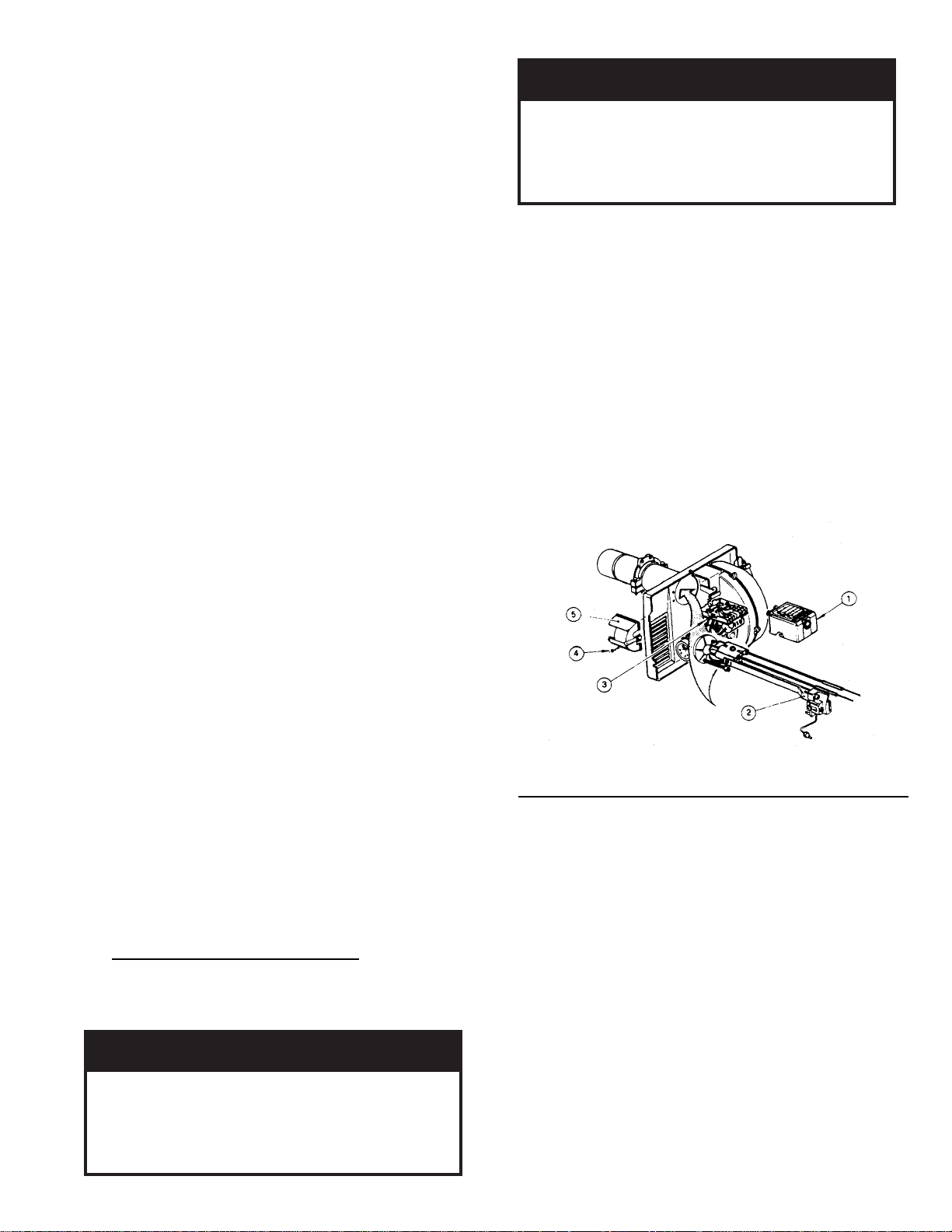
a. Installation/Removal of Drawer assembly, refer
to Figure 7B.
Figure 7B: Installation/Removal of Drawer Assembly
i. Removal:
• Disconnect oil delivery tube nut from
pump.
• Loosen SCREW (3), and then unplug
PRIMARY CONTROL (1) by carefully
pulling it back and then up.
• Remove the AIR TUBE COVER
PLATE (5) by loosening the retaining
SCREW (4) (Two SCREWS-Model F5).
• Loosen SCREW (2), and then slide the
complete drawer assembly out of the
combustion head as shown.
ii. Installation:
To insert drawer assembly, reverse the
procedure in Step i above.
b. Nozzle Replacement, refer to Figure 7C.
19
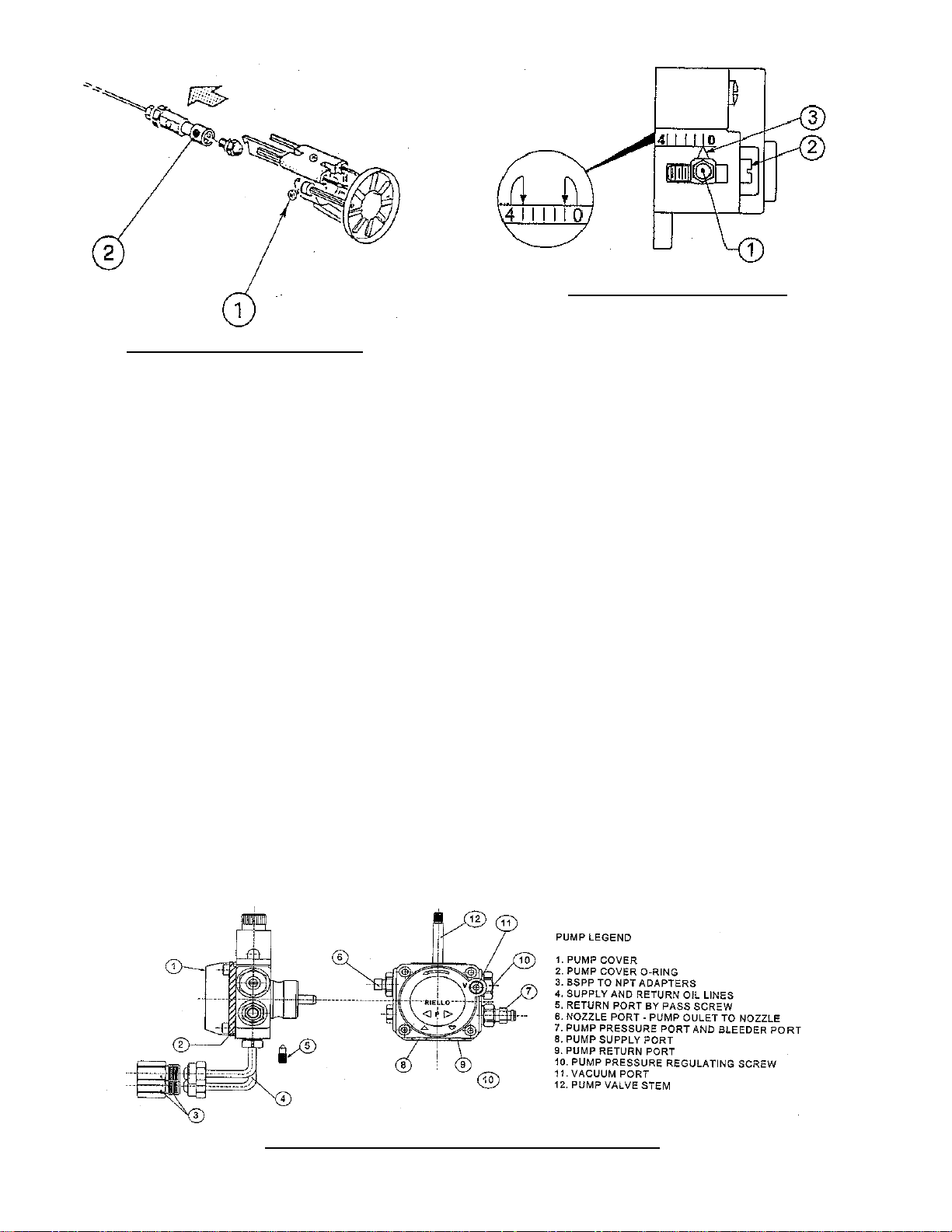
Figure 7C: Nozzle Replacement
i. Remove the nozzle adapter (2) from the
drawer assembly by loosening the screw (1).
ii. Remove existing nozzle from nozzle
adapter.
iii. Insert the proper nozzle into nozzle adapter
and tighten securely (Do not over tighten).
iv. Replace adapter, with nozzle installed, into
drawer assembly and secure with screw (1).
c. Inspect and measure burner electrodes. Refer to
Figure 27D for the proper electrode settings.
d. Re-install Drawer Assembly into Comustion
Head per Step 7c above.
e. Insertion Depth, verify the distance between
the tip of the end cone is equal to the distance
specifi ed in Table 6 of this manual.
f. Turbulator Setting, refer to Figure 7D.
i. Confi rm the turbulator setting is correct
for standard higher (maximum) input
oil nozzle installed in the burner. If the
lower (minimum) input is desired, readjust
turbulator setting to index mark specifi ed in
Table 6 of this manual.
ii. Loosen nut (1) and turn screw (2) until the
index marker (3) is aligned with the correct
index number in the Burner Setup Chart
(Table 6).
Figure 7D: Turbulator Setting
iii. Retighten the retaining nut (1).
MODEL F3 NOTE: Zero and three are scale
indicators only. From left to right the fi rst line is
3 and the last line 0.
MODEL F5: Same as above, except, scale
indicators are 0 and 4.
MODEL F10: Same as above, except, scale
indicators are 0 and 5.
i. Pump Connections and Port Identifi cation,
refer to Figure 7E.
This burner is shipped with the oil pump
set to operate on a single line system. To
operate on a two-line system the bypass
plug must be installed.
WARNING: Do not operate a single line system
with the by-pass plug installed. Operating a
single line system with the by-pass plug installed
will result in damage to the pump shaft seal.
NOTE: Pump pressure was factory pre-set but
must be checked at time of burner start-up. A
pressure gauge is attached to the PRESSURE/
BLEEDER PORT (7) for pressure readings. Two
PIPE CONNECTORS (4) are supplied with the
burner for connection to either a single or twoline system. Also supplied are two ADAPTORS
(3), two female ¼” NPT to adapt oil lines to
burner pipe connectors. All pump port threads
are British Parallel Thread design. Direct
connection of NPT threads to the pump will
damage the pump body.
20
Figure 7E: Pump Connections and Port Identifi cation

Riello manometers and vacuum gauges do not
require any adapters, and can be safely connected
to the pump ports. An NPT x metric adapter
must be used when connecting other gauge
models.
g. Replace Burner Cover and Tighten Burner Cover
Screws.
Water Boilers Only
Select the proper oil nozzle for the installation.
Burners for knockdown V8 water boilers are
shipped with the high (standard) input oil nozzle
installed in the burner.
A second oil nozzle for the lower (minimum)
fi ring rate is shipped loose for the V83 - V86
models, attached to the burner. Either nozzle
may be used with water boilers. The lower
(minimum) input nozzle will provide greater
boiler effi ciency. However, boiler output will be
reduced. Refer to Table 1B for fi ring rates. If
the higher rate is desired, inspect the installed
nozzle and assure that the nozzle is the correct
size and type as specifi ed in Table 6 of this
manual. The nozzle input is stamped on the hex
fl at of the nozzle.
If the lower (minimum) input is desired, remove
the nozzle which was factory installed. Locate
the lower (minimum) fi ring rate nozzle that is
supplied loose. Confi rm the nozzle is the proper
size and type for the lower fi ring rate as specifi ed
in Table 6 of this manual. Install the proper
nozzle in the burner nozzle adaptor.
Proceed to Step c for burner drawer assembly
removal.
N. INSTALL TRIM AND CONTROLS WITH
BECKETT BURNER. - Steam Boiler Only (see
Figures 1D & 5).
1. Thread the pressure gauge into the ¼” NPT tapping
"B", of the front section. Tighten with wrench
applied to the square shank of the gauge.
NOITUAC
.sgnidaeretaruccaninitluseryamsiht
2. Thread 1½” NPT x ¾” NPT bushing and a ¾” NPT
drain valve into the 1½” NPT tapping located in the
lower right corner of the front section. Tighten with
wrench.
ECITON
maetsnonruteretasnednocdradnats
.sreliob
3. Thread safety valve, as shown in Figure 1D, into ¾"
NPT coupling and ¾” NPT x 8” nipple previously
installed in Paragraph H, No. 1, step b. Tighten
with wrench. Pipe discharge as shown in Figure
14. Installation of the safety (relief) valve must be
consistent with ANSI/ASME Boiler and Pressure
Vessel Code, Section IV.
GNINRAW
ebtsumgnipipegrahcsidevlavytefaS
folaitnetopetanimileotroolfraendepip
aeraynaniepiptonoD.snrubereves
lla
tsnitonoD.ruccodluocgnizeerferehw
.spacrosgulp,sevlavffo-tuhsyna
4. Install probe type Low Water Cut-Off (LWCO) if so
equipped.
GNINRAW
snoitcurtsnis’rerutcafunamehtdaeR
reporprofOCWLeborpehthtiwdekcap
nolfeTesuTONOD.noitacilppaepodepip
nac
nolfetfoesU.sdaerhteborpnoepat
.lanoitareponiOCWLeborpehtredner
a. Thread probe into ¾” NPT tapping "C" located
on the front section, down and to the right of
the pressure gauge. Slip the low water cut-off
(LWCO) control over the probe and clamp in
place. Connect the wire(s) between the probe and
control per the manufacturer’s instructions.
b. Install the gauge glass using the two ½” NPT
tappings to the right of the probe LWCO.
5. Install fl oat-type LWCO, if so equipped.
See Figure 8.
a. Install nipples and unions in "D" Tappings.
b. Mount hardware to low water cut-off body.
Install assembly.
c. Install water gage glass on low water cut-off
assembly's tee fi ttings.
6. Install Pressure Limit Control.
-esaceguagehtoterusserpylppatonoD
rofdesusi"H"gnippaTnoitcesraerrewoL
a. Float LWCO only: Remove ¼" NPT plug from
top of Low Water Cut-Off. Install Syphon and
Limit into this tapping. See Figure 8.
b. Probe LWCO only: Install Limit in Tapping "A"
using ¾" NPT x 3" long nipple, ¾" NPT elbow,
¾" NPT x ¼" NPT bushing, and syphon. See
Figure 9.
c. Do not tighten the limit by holding the case;
apply a wrench to the brass hex below the case.
d. Level an L404A pressure limit by carefully
bending the syphon until the limit's leveling
indicator hangs freely with its pointer directly
over the index mark inside the back of the case.
21
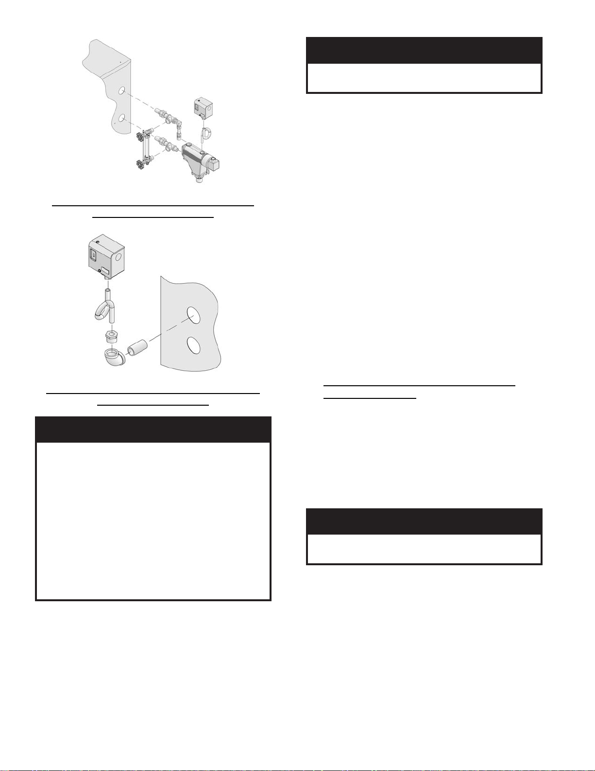
Figure 8: Float-Type Low Water Cut-Off and
Pressure Limit Installation
Figure 9: Pressure Limit Installation for Probe
LWCO Equipped Boilers
ECITON
oD.ebutdelaes
ton
.efillufesustifodneehtta
rucrem
.hsartehtnitimildlo
.ebutdelaesa
.2051-864-008-1
e. An L404F pressure limit does not require
leveling.
7. On units with a heater opening, install the aquastat
controller well in the ½" NPT or ¾” NPT tapping in
tankless heater plate or cover plate. Slip the bulb of
the aquastat into the well and secure the control in
place with the set screw.
22
od,ebutdelaesaniy
ton
tnemeganametsawlacolruoytcatnoC
gnidragersnoitcurtsnirofytirohtua
GNINRAW
otnidetresniyllufebtsumblubtatsauqA
.lleweht
8. Connect the fi eld wiring to the pressure limit, the
LWCO, the R8239A Control Center/J-box and the
burner J-box or burner disconnect J-box.
If equipped with tankless heater, connect fi eld
wiring from the aquastat control to the R8239A
Control Center transformer terminals or oil burner
primary control's "T-T" terminals.
Make the wiring connections as shown in Figures
19, 20 and 21.
NOTE:
• The R7184P Primary Control has pre-installed
"T-T" jumper resistor. To activate "T-T"
terminals, "T-T" jumper must be removed. To
remove, use side cutting pliers to cut jumper (see
Figure 28).
• Do not remove (cut) "T-T" jumper unless
wiring diagram indicates a direct connection
from thermostat and/or tankless heater aquastat
control to the oil burner primary control's "T-T"
terminals.
Refer to Paragraph S for details on use of burner
disconnect junction box provided with all
knockdown boiler builds.
O. INSTALL TRIM AND CONTROLS WITH
BECKETT BURNER. - Water Boilers Only (See
Figures 1A, 1B, 1C and 5).
1. Thread ½” NPT pipe plugs into gauge glass tappings
in the upper right side of front section.
aniyrucremniatnocstimiLerusserPA404L
hsartehtnitimilecalp
sniatnoctahttimilagnicalpersitimilsihtfI
ruoyecalp
2. Thread ¾” NPT pipe plug in probe low water cut off
tapping (just left of gauge glass tappings).
3. Thread combination pressure/temperature gauge into
¼” NPT tapping. Tighten with wrench applied to the
square shank of the gauge.
NOITUAC
sihtfolasopsidreporpehtdnagnilcycer
niyrucremgniniatnoctimildlonaforo,timil
ta.cnIllewyenoHllac,snoitseuqevahuoyfI
4. Screw drain valve into ¾" NPT side outlet of the
1½” NPT x 90° elbow (note - lower front section
tapping “G” is used for standard return on water
boilers).
5. If circulator (not supplied with boiler) is to be
mounted directly to 1½" NPT boiler return tapping
"G", use the piping arrangements outlined in steps a.
thru e. as follows: (see Figures 13A, 13B and 13C)
a. Thread 1½” NPT x 3” long nipple and 1½”
NPT x 90° elbow with ¾" NPT side outlet
into the return tapping and tighten with a pipe
wrench.
-esaceguagehtoterusserpylppatonoD
.sgnidaeretaruccaninitluseryamsiht

b. Thread 1½” NPT x 15” long nipple into the 1½"
NPT x 90° elbow and tighten with a pipe wrench.
c. Thread one of the circulator fl ange onto the
nipple and tighten with a pipe wrench. Position
fl ange so that the bolt slots are parallel to the
boiler front.
d. Place a circular fl ange gasket in the fl ange
groove on the circulator and mount the circulator
on the fl ange. Note that this is the return piping
and the fl ow arrow on the circulator should point
down Ð. Fasten circulator with 7/16” - 14 x 1½"
long cap screws and 7/16" - 14 nuts.
e. Fasten the second circulator fl ange and gasket to
the circulator.
6. Install relief valve, as shown in Figure 1A, 1B, and
1C, onto ¾” NPT x 8” nipple previously installed in
Paragraph H, No. 2, step b. Tighten with wrench.
Pipe discharge as shown in Figures 13A, 13B
and 13C. Installation of the relief valve must be
consistent with ANSI/ASME Boiler and Pressure
Vessel Code, Section IV.
GNINRAW
ebtsumgnipipegrahcsidevlavytefaS
folaitnetopetanimileotroolfraendepip
aeraynaniepiptonoD.snrubereves
llatsnitonoD.ruccodluocgnizeerferehw
.spacrosgulp,sevlavffo-tuhsyna
7. On units without a heater opening, install the well
into the ¾” NPT tapping "A" located on the front of
the boiler in the upper left corner. See Figures 1A
and 5. Tighten the well and insert the control’s bulb
into the well. Secure control to well with set screw.
GNINRAW
NOTE:
• Do not remove (cut) "T-T" jumper on R7184P
Primary Control for application 9a or 9b
above.
c. Refer to Paragraph S for details on use of burner
disconnect junction box provided with all
knockdown boiler builds.
P. INSTALL TRIM AND CONTROLS WITH
CARLIN 102CRD BURNER.
Follow instructions in Paragraph N, Steps 1 through 7.
Steam Boilers Only (see Figures 1D and 5).
8. Connect Field Wiring
a. Steam Boiler with Hydrolevel CG450 LWCO,
Carlin Burner.
Connect the fi eld wiring to the pressure limit, the
LWCO, R8239C Control Center and the burner
disconnect J-box or directly to burner J-box on
burners less disconnect harness (power cord).
If equipped with tankless heater, connect fi eld
wiring from the aquastat control to the R8239C
Control Center’s “R-G” terminals. Make the
wiring connections as shown in Figure 19A.
b. Steam Boiler with McDonnell & Miller
PS-801 or McDonnell & Miller 67 LWCO,
Carlin Burner.
Connect the fi eld wiring to the LWCO, the
pressure limit and the burner disconnect J-box.
If equipped with tankless heater, connect fi eld
wiring from the aquastat control to the oil burner
primary control’s “T-T” Terminals. Make the
wiring connections as shown in Figures 20A, and
21A.
c. Refer to Paragraph S for details on use of burner
disconnect junction box provided with all
knockdown boiler builds.
otnidetresniyllufebtsumblubtatsauqA
.lleweht
8. On units with a heater opening, install the well in
the ½" NPT or ¾” NPT tapping on the tankless
heater plate or cover plate. See Figures 1B, 1C and
5. Tighten the well and insert the control’s bulb into
the well. Secure control to well with set screw.
9. Connect Field Wiring.
a. Water boilers without tankless heater and with
front tankless heater. Connect the fi eld wiring
from the circulator to the aquastat control and
from the control to the burner disconnect J-box
or directly to the burner J-box. Make the wiring
connections as shown on Figures 22, 23A and
23D.
b. Water boilers with rear tankless heater. Connect
the fi eld wiring from a standard junction box
or burner disconnect J-box to the circulator,
aquastat control and burner. Make the wiring
connections as shown on Figure 23B.
Water boilers Only (see Figures 1A, 1B, 1C and 5).
Follow instructions in Paragraph O, Steps 1 through 7
9. Connect Field Wiring
a. Water boilers without tankless heater and with
front tankless heater. Connect the fi eld wiring
from the circulator to the aquastat control and
from the control to the burner disconnect J-box
or directly to oil burner primary control on
burners less disconnect harness (power cord).
Make the wiring connections as shown on
Figures 22A and 23B .
b. Water boilers with rear tankless heater. Connect
the fi eld wiring from a standard junction box
or burner disconnect J-box to the circulator,
aquastat control and burner. Make the wiring
connections as shown on Figure 23E.
c. Refer to Paragraph S for details on use of burner
disconnect junction box provided with all
knockdown boiler builds.
23

Q. INSTALL TRIM AND CONTROLS WITH
CARLIN ELITE EZ BURNER.
Follow instructions in Paragraph N, Steps 1 through 7.
Steam Boilers Only (see Figures 1D and 5).
8. Connect Field Wiring
a. Steam Boiler with Hydrolevel CG450 LWCO,
Carlin Burner.
Connect the fi eld wiring to the pressure limit, the
LWCO, R8239C Control Center and the burner
disconnect J-box or directly to burner J-box on
burners less disconnect harness (power cord).
If equipped with tankless heater, connect fi eld
wiring from the aquastat control to the R8239C
Control Center’s “R-G” terminals. Make the
wiring connections as shown in Figure 19.
b. Steam Boiler with McDonnell & Miller
PS-801 or McDonnell & Miller 67 LWCO,
Carlin Burner.
Connect the fi eld wiring to the pressure limit,
the R8239C Control Center, the LWCO and
the burner disconnect J-box. If equipped with
tankless heater, connect fi eld wiring from
the aquastat control to the oil burner primary
control’s “T-T” Terminals. Make the wiring
connections as shown in Figures 20 and 21.
c. Refer to Paragraph S for details on use of burner
disconnect junction box provided with all
knockdown boiler builds.
Water boilers Only (see Figures 1A, 1B, 1C and 5).
Follow instructions in Paragraph O, Steps 1 through 7.
9. Connect Field Wiring
a. Water boilers without tankless heater and with
front tankless heater. Connect the fi eld wiring
from the circulator to the aquastat control and
from the control to the burner disconnect J-box
or directly to oil burner primary control on
burners less disconnect harness (power cord).
Make the wiring connections as shown on
Figures 22 and 23A.
b. Water boilers with rear tankless heater. Connect
the fi eld wiring from a standard junction box
or burner disconnect J-box to the circulator,
aquastat control and burner. Make the wiring
connections as shown on Figure 23B.
c. Refer to Paragraph S for details on use of burner
disconnect junction box provided with all
knockdown boiler builds.
R. INSTALL TRIM AND CONTROLS WITH
RIELLO BURNER.
Follow instructions in Paragraph N, Steps 1 through 7.
Steam Boilers Only (see Figures 1D and 5).
8. Connect Field Wiring
a. Steam boiler with Hydrolevel CG450 or
McDonnell & Miller 67 LWCO, Riello Burner.
Connect the fi eld wiring to the pressure limit,
the LWCO, R8239C Control Center and the
burner disconnect J-box or directly to oil burner
primary control on burners less disconnect
harness (power cord). If equipped with tankless
heater, connect fi eld wiring from the aquastat
control to the R8239C Control Center’s “R-G”
terminals. Make the wiring connections as shown
in Figures 19 and 21.
b. Steam boiler with McDonnell & Miller PS-801
LWCO, Riello Burner.
Connect the fi led wiring to the pressure limit,
the R8239C Control Center, the LWCO and the
burner J-box. If equipped with tankless heater,
connect fi eld wiring from the aquastat control to
the R8239C Control Center’s “R-G” terminals.
Make the wiring connections as shown in Figure
20.
c. Refer to Paragraph S for details on use of burner
disconnect junction box provided with all
knockdown boiler builds.
Water Boilers Only (see Figures 1A, 1B, 1C and 5).
Follow instructions in Paragraph O, Steps 1 through 7.
9. Connect Field Wiring
a. Water boilers without tankless heater and with
front tankless heater. Connect the fi eld wiring from
the circulator to the aquastat control and from the
control to the burner disconnect J-box or directly
to oil burner primary control on burners less
disconnect harness (power cord). Make the wiring
connections as shown on Figures 22 and 23A.
b. Water boilers with rear tankless heater. Connect the
fi eld wiring from a standard junction box or burner
disconnect J-box to the circulator, aquastat control
and burner. Make the wiring connections as shown
on Figure 23B.
c. Refer to Paragraph S for details on use of burner
disconnect junction box provided with all
knockdown boiler builds.
S. BURNERS SUPPLIED BY BURNHAM utilize
a burner disconnect harness that is pre-wired into the
burner junction box and primary control. Packed in the
canopy carton is the mating burner disconnect junction
assembly and mounting hardware for use with these
burners.
If you are using a burner with the disconnect harness,
complete the following assembly instructions for
mounting the mating burner disconnect junction box,
see Figure 10.
24
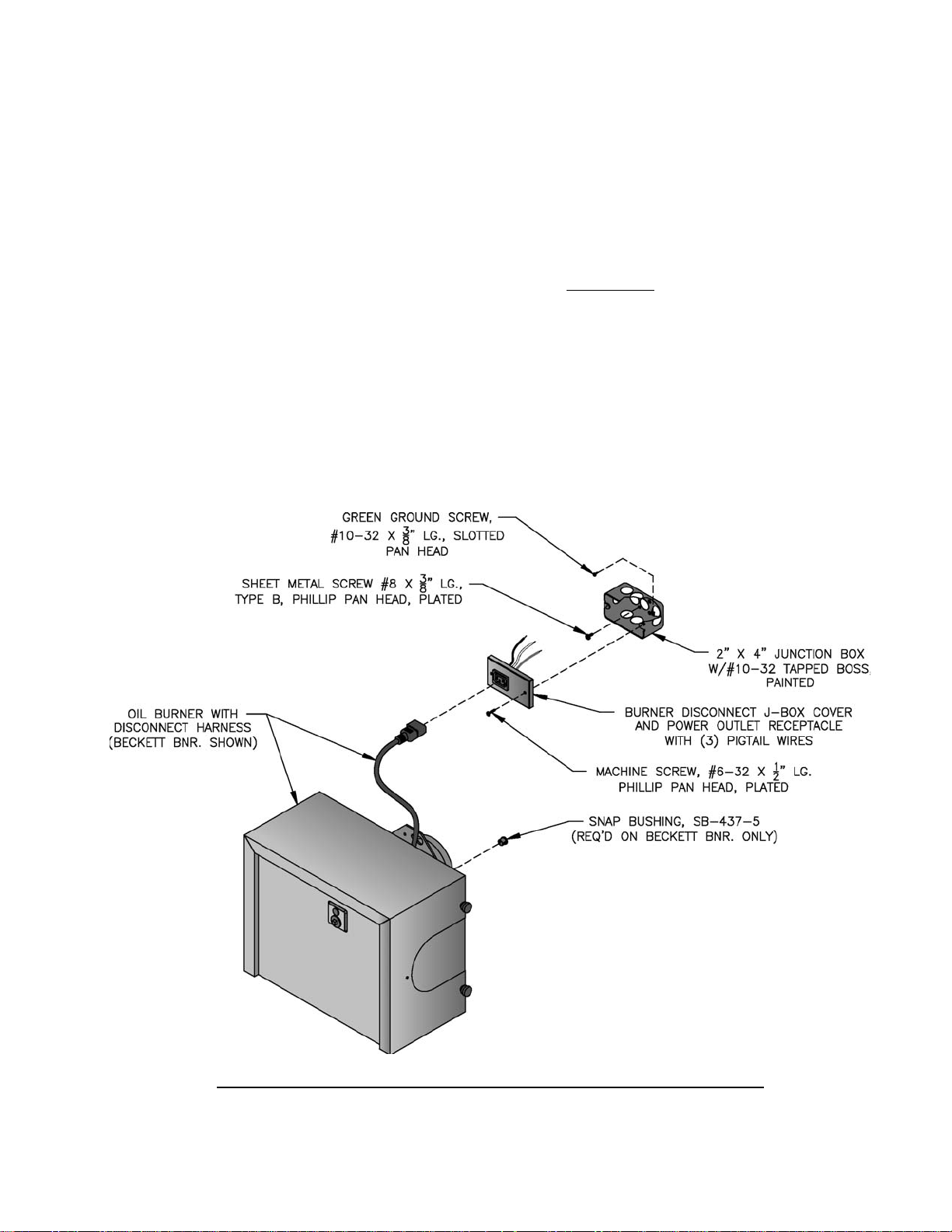
1. Remove (2) #6 x 1/2" lg. machine screws and J-box
cover from junction box.
2. Secure 2" x 4" junction box to jacket front panel
with (2) #8 x 3/8" lg. sheet metal screws using prepunched holes below tridicator or pressure gauge
tapping.
3. Complete the fi eld wiring phase of Paragraphs N &
O (Beckett), P (Carlin 102CRD), Q (Carlin Elite
EZ) or R (Riello) Install end of harness from low
water cut-off (LWCO), R8239A Control Center
or Aquastat Control into appropriate knockout of
burner disconnect junction box according to source,
refer to Figures 1A thru 1D.
4. Use wire nuts to connect wires from control or
power source to (3) pigtail wires connected to spade
terminals on rear of power outlet receptacle. Make
the connections as shown in appropriate wiring
diagram based on boiler confi guration, refer to
Figures 19 thru 23F.
5. Secure J-box cover to junction box with (2) #6 x ½"
lg. machine screws.
6. Insert mating end of burner disconnect harness
(power cord) into power outlet receptacle on J-box.
7. Install snap bushing into 7/16" diameter hole in
upper right corner of burner enclosure back plate
on all Beckett burners, see Figure 10. On certain
builds, 18/2 wire from L4006A Aquastat Control
mounted in rear heater will pass through this snap
bushing and connect to "T-T" terminals on primary
control, refer to Figures 20 and 21.
IMPORTANT: Remove (cut) jumper resistor on
R7184P Primary Control to activate "T-T" terminals
when making a direct connection from thermostat
and/or tankless heater aquastat control.
Figure 10: Burner Disconnect Junction Box with Power Outlet Receptacle
(Mated to Burners with Disconnect Harness)
25
SECTION III: PACKAGED BOILER ASSEMBLY
A. REMOVE CRATE.
1. Remove all fasteners at crate skid.
2. Lift outside container and remove all other inside
protective spacers and bracing. Remove draft
regulator box and miscellaneous trim bag containing
safety or relief valve, and pipe fi ttings.
B. REMOVE BOILER FROM SKID.
1. Boiler is secured to base with 4 bolts, 2 in front and
2 in rear of shipping skid, see Figure 11. Remove all
bolts.
Figure 11: Packaged Boiler Removal from Skid
2. Tilt boiler to right and to rear. Using right rear leg
as pivot, rotate boiler 90° in a clockwise direction,
and lower left side of boiler to fl oor. Tilt boiler and
remove crate skid. Care should be exercised to
prevent damage to jacket or burner.
NOITUAC
reliobpmubtonoD.reliobpordtonoD
.roolftsniagatekcaj
C. MOVE BOILER TO PERMANENT POSITION
by sliding or walking.
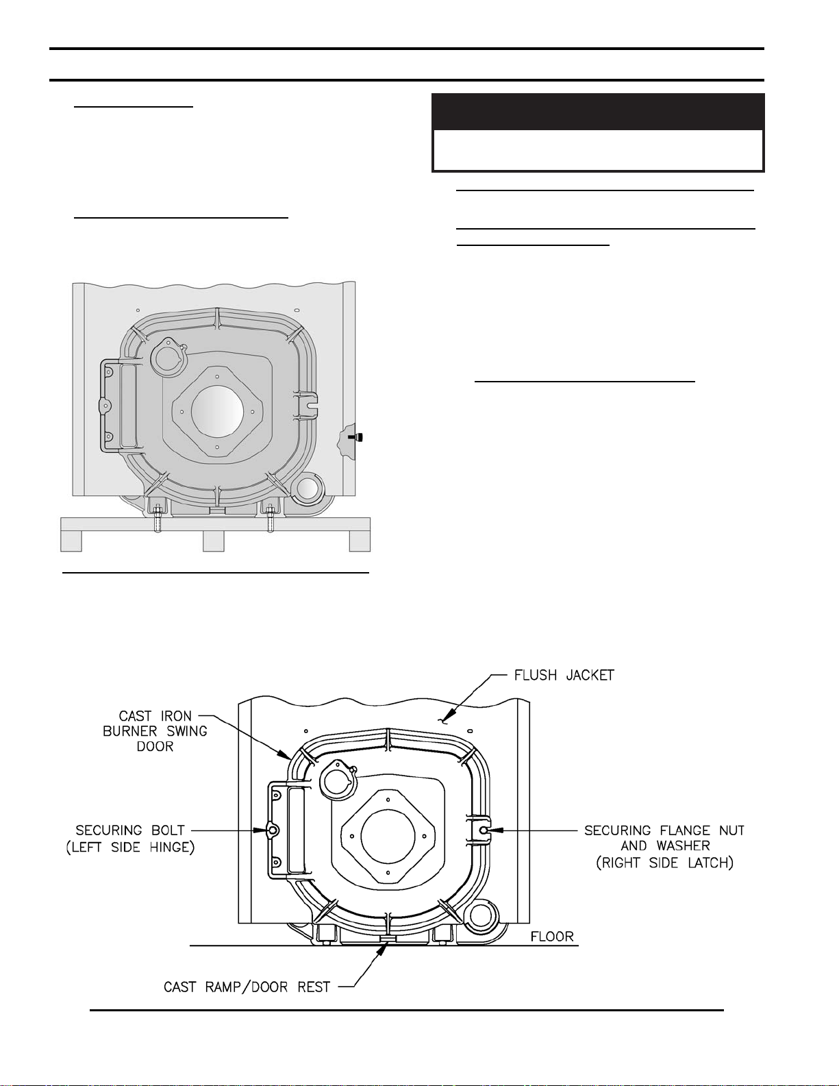
D. PROCEDURE TO OPEN, CLOSE AND SECURE
BURNER SWING DOOR with articulated hinge.
Throughout this manual you will be instructed to
open and close the burner swing door for various
reasons. There is a proper and improper method to
closing and securing the burner swing door after it
has been removed and re-installed for Field Assembly
(Knockdown Boiler) or opened for inspection, cleaning
or fi eld service.
1. TO OPEN BURNER SWING DOOR (see Figures
11A and 11B).
Step 1. Loosen and remove right side latching
hardware (5/16" fl ange nut and washer).
Step 2. Loosen and remove left side hinge hardware
(5/16" x 3-1/2" lg. hex head fl ange bolt).
Step 3. The duel pivot articulated hinge allows right
side of door to be pulled outward and rotated
to the left all in one motion. To do so, place
your right hand under burner air tube and lift up
slightly to help carry the weight of the door and
burner. Use your left hand to grasp the door's
left side hinge fl ange, pull outward to rotate the
hinge, this motion will move the door outward
and to the left approximately 3" (see Figure 11B,
Position 2).
Figure 11A: Partial Front View - Burner Swing Door Mounted to Boiler - Fully Closed and Secured
26
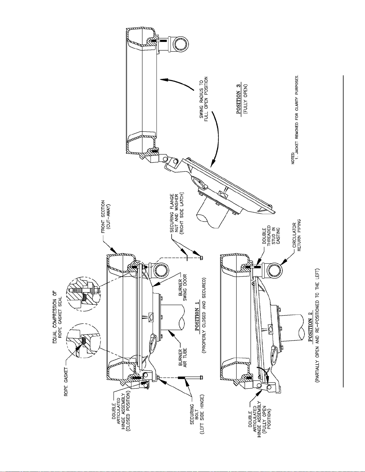
Figure 11B: Top View - Burner Swing Door Mounted to Cast Iron Block Assembly (Jacket Removed for Clarity)
27
Step 4. From this position the door can be swung
clear of the vertical circulator return piping to
provide full access to the combustion chamber
and burner head (see Figure 11B, Position 3).
2. Perform routine inspection, service or cleaning as
necessary.
3. To close Burner Swing Door (see Figures 11A and
11B):
Step 1. From the fully open position, rotate Burner
Swing Door toward the closed position. Make
sure that the articulated hinge is rotated to the
extreme left position to allow the door to clear
the vertical circulator return piping as shown in
Figure 11B, Position 2.
Step 2. Grasp the door's left side hinge fl ange
in your left hand and place your right hand
under the burner air tube to lift upward. Lift
the door up unto the built-in cast ramp/door
rest (protruding from the bottom of the front
section casting - see Figure 11A), while rotating
the articulated hinge and door to the right and
engaging the slot (on right side of door) unto the
5/16" stud protruding from the front section.
Step 3. Use one hand to help hold door in position
by lifting up on rear burner housing or applying
pressure directly to the door while re-installing
the securing hardware with your opposite hand.
Always install right side latching hardware
(5/16" fl ange nut and fl at washer) fi rst, then
install left side hinge hardware (5/16" x 31/2" lg. hex head fl ange bolt) second. Apply
additional pressure while hand tightening the
hardware as far as possible, then release the
pressure.
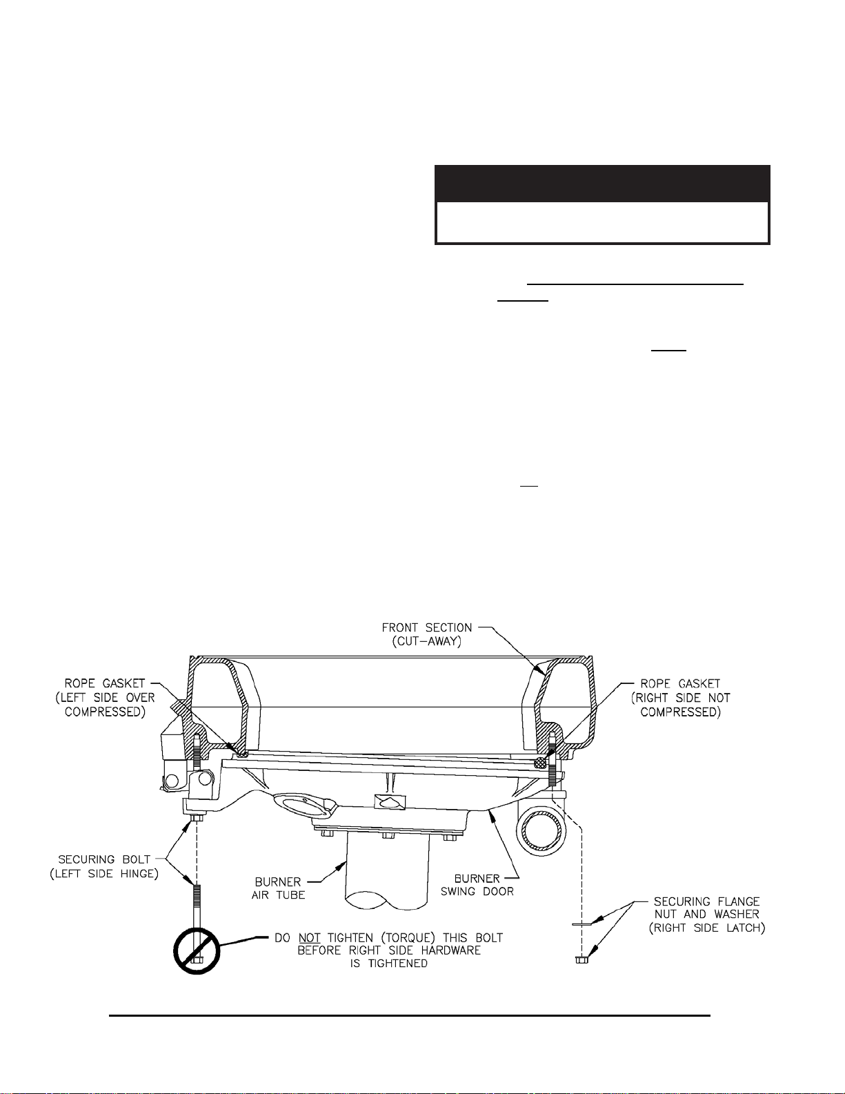
ECITON
ekamroodgniwsrenrubgnirucesnehW
.sedishtobnoyllauqeni-nwardsirooderus
Step 4. Use a hand wrench to tighten door hardware
and always start with the right side fl ange
nut fi rst. Use an alternating tightening method
from right side fl ange nut to left side fl ange
bolt to tighten door equally until sealed without
applying excessive torque. Never tighten left
side fl ange bolt fi rst or tighten either piece of
hardware 100% without using the alternating
tightening method described above.
Failure to follow the prescribed procedure could
cause thread damage to casting or a leak in the
door seal. If left side fl ange bolt is tightened
before right side fl ange nut, right side of door
can not be drawn-in to provide an air tight seal,
as shown in Figure 11C. Applying excessive
torque will only cause thread damage.
28
Figure 11C: Top View - Burner Swing Door Fully Closed but Not Properly Secured or Sealed

E. INSPECT COMBUSTION CHAMBER TARGET
WALL AND LINER, AND SWING DOOR
GASKET.
1. Open burner swing door using procedure previously
outlined in Paragraph D of this section.
2. Using a fl ashlight, inspect the rear target wall and
liner. The target wall should be rigidly secured to
the rear boiler section. The combustion chamber
liner should be evenly distributed in the boiler
chamber. If either is damaged, they must be
replaced.
3. Inspect ceramic rope located on the swing door.
The rope must be evenly distributed around the
perimeter of the door groove and cannot bunch or
overhang. There must not be a gap where the two
ends of the rope meet. Repair or replace if the rope
is damaged or if there is a gap between the ends.
F. INSPECT NOZZLE AND ELECTRODES /
CHANGE FIRING RATE FOR BECKETT
BURNERS. Refer to Section II, Paragraph J, No. 7,
steps b through o for nozzle installation, electrode and
head setting inspection.
Steam Boilers Only
Packaged V83 - V86 steam boilers are shipped with
the lower (standard) fi ring rate nozzle installed.
Packaged V87 - V89 boilers are provided with one
nozzle, installed in the burner, that provides the
same fi ring rate as the water boiler of the same size.
Inspect the installed nozzle and assure that the
nozzle is the correct size and type as specifi ed in
Table 6 of this manual.
Inspect and measure burner electrodes. Refer to
Figure 27 of this manual for the proper electrode
settings.
Close the burner swing door and securely seal the
door to the boiler front section by reinstalling the
hardware and securing the door using procedure
previously outlined in Paragraph D of this section.
Water Boilers Only
Packaged V8 water boilers are shipped with the
higher input oil nozzle installed in the burner.
A second oil nozzle for the lower (minimum) fi ring
rate is shipped loose for the V83 - V86 models,
attached to the burner. Select the proper oil
nozzle for the installation. The lower (minimum)
input nozzle will provide greater boiler effi ciency.
However, boiler output will be reduced. Refer to
Table 1B for ratings. If the higher rate is desired,
inspect the installed nozzle and assure that the
nozzle is the correct size and type as specifi ed in
Table 6 of this manual.
If the lower (minimum) input is desired, remove
the nozzle which was factory installed. Locate the
lower (minimum) fi ring rate nozzle that is supplied
loose. Confi rm the nozzle is the proper size and
type for the lower fi ring rate as specifi ed in Table
6 of this manual. Install the proper nozzle in the
burner nozzle adaptor.
G. INSPECT NOZZLE AND ELECTRODES
/ CHANGE FIRING RATE FOR CARLIN
102CRD BURNERS. Refer to Section II, Paragraph
K, No. 7, steps b through d for nozzle installation,
electrode and head setting inspection.
Follow instructions in Paragraphs A through E.
Steam or Water Boilers
Packaged V87 - V89 steam boilers are provided
with one nozzle, installed in the burner, that
provides the same fi ring rate as the water boiler of
the same size.
Inspect the installed nozzle and assure that the
nozzle is the correct size and type as specifi ed in
Table 6 of this manual.
H. INSPECT NOZZLE AND ELECTRODES /
CHANGE FIRING RATE FOR CARLIN ELITE
EZ BURNERS. Refer to Section II, Paragraph L, No.
7, steps a through c for nozzle installation, electrode
and head setting inspection.
Follow instructions in Section III, Paragraphs A through
E.
Steam Boilers Only
Packaged V83 - V86 steam boilers are shipped with
the lower (standard) fi ring rate nozzle installed.
Packaged V87 - V89 boilers are provided with one
nozzle, installed in the burner, that provides the
same fi ring rate as the water boiler of the same size.
Inspect the installed nozzle and assure that the
nozzle is the correct size and type as specifi ed in
Table 6.
Water Boilers Only
Packaged V8 water boilers are shipped with the
higher input oil nozzle installed in the burner.
A second oil nozzle for the lower (minimum) fi ring
rate is shipped loose for the V83 - V86 models,
attached to the burner. Select the proper oil
nozzle for the installation. The lower (minimum)
input nozzle will provide greater boiler effi ciency.
However, boiler output will be reduced. Refer
to Table 1B For fi ring rates. If the higher rate is
desired, inspect the installed nozzle and assure that
the nozzle is the correct size and type as specifi ed in
Table 6.
29

If the lower (minimum) input is desired, remove
the nozzle which was factory installed. Locate the
lower (minimum) fi ring rate nozzle that is supplied
loose. Confi rm the nozzle is the proper size and
type for the lower fi ring rate as specifi ed in Table
6. Install the proper nozzle in the burner nozzle
adaptor.
I. INSPECT NOZZLE AND ELECTRODES
/ CHANGE FIRING RATE FOR RIELLO
BURNERS. Refer to Section II, Paragraph M, No. 7,
steps a through g for nozzle installation, electrode and
head setting inspection.
Steam Boilers Only
Packaged V83 - V86 steam boilers are shipped with
the lower (standard) fi ring rate nozzle installed.
Packaged V87 - V89 boilers are provided with one
nozzle, installed in the burner, that provides the
same fi ring rate as the water boiler of the same size.
Inspect the installed nozzle and assure that the
nozzle is the correct size and type as specifi ed in
Table 6 of this supplement.
Water Boilers Only
Packaged V8 water boilers are shipped with the
higher input oil nozzle installed in the burner.
A second oil nozzle for the lower (minimum) fi ring
rate is shipped loose for the V83 - V86 models,
attached to the burner. Select the proper oil
nozzle for the installation. The lower (minimum)
input nozzle will provide greater boiler effi ciency.
However, boiler output will be reduced. Refer
to Table 1B for fi ring rates. If the higher rate is
desired, inspect the installed nozzle and assure that
the nozzle is the correct size and type as specifi ed in
Table 6.
If the lower (minimum) input is desired, remove
the nozzle which was factory installed. Locate the
lower (minimum) fi ring rate nozzle that is supplied
loose. Confi rm the nozzle is the proper size and
type for the lower fi ring rate as specifi ed in Table
6. Install the proper nozzle in the burner nozzle
adaptor.
GNINRAW
folaitnetopetanimileotroolfraendepipeb
aeraynaniepiptonoD.snrubereves
llatsnitonoD.ruccodluocgnizeerferehw
.spacrosgulp,sevlavffo-tuhsyna
K. PACKAGED BOILERS WITH PROBE STYLE
LWCO. Install Limit in Tapping "A" using ¾" NPT x
2" nipple, ¾" NPT elbow, ¾" NPT x ¼" NPT bushing,
and syphon included in trim bag. See Figure 9.
1. Do not tighten the limit by holding the case; apply a
wrench to the brass hex below the case.
2. Connect wiring harness from Low Water Cut-Off to
steam pressure limit.
3. Level an L404A pressure limit by carefully bending
the syphon until the limit's leveling indicator hangs
freely with its pointer directly over the index mark
inside the back of the case.
ECITON
aniyrucremniatnocstimiLerusserPA404L
oD.ebutdelaes
ton
.efillufesustifodneehtta
od,ebutdelaesaniyrucrem
ton
.hsartehtnitimildlo
gnidragersnoitcurtsnirofytirohtua
opsidreporpehtdnagnilcycer
.ebutdelaesa
.2051-864-008-1
4. An L404F pressure limit does not require leveling.
hsartehtnitimilecalp
sniatnoctahttimilagnicalpersitimilsihtfI
tnemeganametsawlacolruoytcatnoC
sihtfolas
tsumgnipipegrahcsidevlavfeilerroytefaS
ruoyecalp
niyrucremgniniatnoctimildlonaforo,timil
ta.cnIllewyenoHllac,snoitseuqevahuoyfI
J. INSTALL SAFETY OR RELIEF VALVE IN
TAPPING "M".
Use ¾" NPT x 8" nipple and/or ¾" NPT coupling
included in trim bag. Safety or Relief Valve must
be installed with spindle in vertical position. Pipe
discharge as shown in Figures 13A, 13B, 13C and
14. Installation of the safety or relief valve must be
consistent with ANSI/ASME Boiler and Pressure
Vessel Code, Section IV.
30

SECTION IV: WATER BOILER PIPING AND TRIM
ECITON
.revoyrracretawdnasnoitautculf
enilretaw,esionmetsysevissecxenitluseryamlaunamsihtnideificepssareliobepipoteruliaF
A. EVALUATE THE EXISTING WATER SYSTEM.
Design a piping system and install boiler which will
prevent oxygen contamination of boiler water and
frequent water additions.
1. There are many possible causes of oxygen
contamination such as:
a. Addition of excessive make-up water as a result
of system leaks.
b. Absorption through open tanks and fi ttings.
c. Oxygen permeable materials in the distribution
system.
2. In order to insure long product life, oxygen sources
must be eliminated. This can be accomplished by
taking the following measures:
a. Repairing system leaks to eliminate the need for
addition of make-up water.
b. Eliminating open tanks from the system.
c. Eliminating and/or repairing fi ttings which allow
oxygen absorption.
d. Use of non-permeable materials in the
distribution system.
e. Isolating the boiler from the system water by
installing a heat exchanger.
GNINRAW
tsumgnipipnruterdnaylppusmetsyS
.epipreliobtcerrocotdetcennoceb
ehtgnizissdnemmocermahnruB
pusotrotalucricmetsys
.deredisnocebtsumgnipip
tneiciffusylp
erutarepmetF°02awollaot)MPG(wolf
gnizisnehW.metsysehtnilaitnereffid
erusserpeht,rotalucricmetsyseht
dnadraobesab,srotaidarllafopord
gnitcennoclladnagnibuttnaidar
NOITUAC
morfecnaraelchcni½muminimniatniaM
.slairetamelbitsubmocotgnipipretawtoh
B. CONNECT SYSTEM SUPPLY AND RETURN
PIPING TO BOILER. See Figures 13A, 13B and
13C. Also, consult I=B=R Installation and Piping
Guides.
1. If this boiler is used in connection with refrigeration
systems, the boiler must be installed so that the
chilled medium is piped in parallel with the heating
boiler using appropriate valves to prevent the chilled
medium from entering the boiler. See Figure 12.
Also, consult I=B=R Installation and Piping Guides.
2. If this boiler is connected to heating coils located
in air handling units where they may be exposed
to refrigerated air, the boiler piping must be
equipped with fl ow control valves to prevent gravity
circulation of boiler water during the operation of
the cooling system.
3. If boiler is used with an Alliance™ Indirect-Fired
Domestic Water Heater, install the Alliance™ as
a separate heating zone. Refer to the Alliance™
Installation, Operating, and Service Instructions for
additional information.
4. Use a boiler bypass if the boiler is to be operated
in a system which has a large volume or excessive
radiation where low boiler water temperatures may
be encountered (i.e. converted gravity circulation
system, etc.) The bypass should be the same size as
the supply and return lines with valves located in the
bypass and return line as illustrated in Figures 13A,
13B and 13C in order to regulate water fl ow for
maintenance of higher boiler water temperature.
GNINRAW
elihw,ecivedffo-tucretawwolafoesuehT
wolebsilevelnoitaidarsselnuderiuqerton
.dednemmocerylhgihsi,reliobeht
If a low water cut-off is required, it must be
mounted in the system piping above the boiler. The
minimum safe water level of a hot water boiler is
just above the highest water containing cavity of
the boiler; that is, a hot water boiler must be full of
water to operate safely.
5. If it is required to perform a long term pressure
test of the hydronic system, the boiler should fi rst
be isolated to avoid a pressure loss due to the escape
of air trapped must fi rst be removed from the boiler.
31

To perform a long term pressure test including the
boiler, ALL trapped air must fi rst be removed from
the boiler.
A loss of pressure during such a test, with no
visible water leakage, is an indication that the boiler
contained trapped air.
Figure 12: Recommended Piping for Combination Heating and Cooling (Refrigeration) System
32

Figure 13A: Recommended Water Piping for Circulator Zoned Heating System
33

34
Figure 13B: Recommended Water Piping for Zone Valve Zoned Heating System - Supply Side Circulator

Figure 13C: Recommended Water Piping for Zone Valve Zoned Heating System - Return Side Circulator
35

SECTION V: STEAM BOILER PIPING AND TRIM
GNINRAW
.erutcurts
.sgnitarehtevobatupnireliobmaetsesaercnitonoD
roreliobotegamaddnanoitareporeporpminitluseryamreliobepipylreporpoteruliaF
A. EVALUATE THE EXISTING STEAM SYSTEM.
The single most important factor in determining the
expected life cycle of a steam boiler, is the amount of
fresh water added to the boiler during operation. Fresh
water brings minerals and oxygen into the boiler. These
contaminants greatly accelerate corrosion of the cast
iron boiler sections.
1. Assure that all system radiators, piping and vents are
absolutely leak tight.
a. When a steam boiler is installed in an existing
system, ALL air vents should be replaced at the
same time. This assures that the new boiler will
not be compromised by existing system leaks.
b. If the system contains hidden supply or return
piping (hidden behind walls, buried in concrete,
etc.) pressure test this piping to assure there are
no leaks.
.retawfonoitiddatneuqerf
:gnipip
)1 esuacdnasessertslacinahcemecudninacnoisnapxelamrehtfotneiciffeochgih
,noitallatsni
)2 ehtnidedulcniebtsumgnipipreppocdetalusninufo)ssoltaeh(etarrefsnarttaehhgih
)3 taehroopesuacnacmetsysehtnipudnetahtsexulfdnasetsapgnizarbrogniredlos
,dnaerudecorptuoliobehtgnirud
)4 niatrecnislatemralimissidoteudruccoyamlatemgniniojdaehtfonoisorroccinavlag
2. Repair any leaks in the system.
3. Install accurate water meter on the fresh water
supply to the boiler.
B. CONNECT SYSTEM SUPPLY AND RETURN
PIPING TO BOILER. See Figure 14 for piping
details. Also consult I=B=R Installation and Piping
Guides.
NOITUAC
morfecnaraelchcni½muminimniatniaM
.slairetamelbitsubmocotgnipipretawtoh
ECITON
nieiT.tluserlliwnoisorrocreliobdetareleccA.sreliobmaetsniretawdenetfosesutonoD
.renetfosretawafomaertspureliobehtotylppusretawhserf
reliobleetsdnanorifonoisorrocesuaclliwretawreliobfonoitanimatnocnegyxO
revoctonseodytnarraWdradnatSs'mahnruB.eruliafreliobotdaelnacdna,stnenopmoc
ybdesuacpu-dliub)emil(elacsroretawreliobfonoitanimatnocnegyxoybdesuacsmelborp
reppocfoscitsiretcarahcgniwollofehtredisnoc,gnipipmaetsrofreppocgnisuerofeB
dnangisedmetsysgnipipehtnirofdetnuoccatonfisesionnoitcartnoc/noisnapxe
,reliobehtezisotdesusrotcafpukcipdnagnipiplamron
devomerylhguorohttonfimaetstewdnaenilretawydaetsnuna,gnigrus,refsnart
.desutonerasnoinucirtceleidfiseirtsimehcretaw
36

ECITON
enilretaw,esionmetsysevissecxenitluseryamlaunamsihtnideificepssareliobepipoteruliaF
.revoyrracretawdnasnoitautculf
Figure 14: V83 Thru V89 Recommended Boiler Piping For Gravity Return Steam Boiler
37

SECTION VI: TANKLESS AND INDIRECT WATER HEATER PIPING
A. CONNECT TANKLESS HEATER PIPING as
shown in Figure 15A. See Tables 2A and 2B for
Tankless Heater Rating.
GNINRAW
sselknattaevlavgniximcitamotuallatsnI
rosnrubfoksirdiovaotteltuoretaeh
taretawtohylevissecxeoteudgnidlacs
gniximehtniatniamdnatsujdA.serutxif
sselknatetarepotonoD.snoitcurtsni
.evlavgniximtuohtiwretaeh
THE FOLLOWING GUIDELINES SHOULD BE
FOLLOWED WHEN PIPING THE TANKLESS
HEATER:
1. FLOW REGULATION — If fl ow through the
heater is greater than its rating, the supply of
adequate hot water may not be able to keep up
with the demand. For this reason a fl ow regulator
matching the heater rating should be installed in
the cold water line to the heater. The fl ow regulator
should preferably be located below the inlet to the
heater and a minimum of 3’ away from the inlet
so that the regulator is not subjected to excess
temperatures that may occur during “off” periods
when it is possible for heat to be conducted back
through the supply line. The fl ow regulator also
limits the fl ow of supply water regardless of inlet
pressure variations in the range of 20 to 125 psi.
2. TEMPERING OF HOT WATER — Installation
of an automatic mixing valve will lengthen the
delivery of the available hot water by mixing some
cold water with the hot. This prevents the possibility
of scalding hot water at the fi xtures. In addition,
savings of hot water will be achieved since the user
will not waste as much hot water while seeking a
water temperature. Higher temperature hot water
required by dishwashers and automatic washers is
possible by piping the hot water from the heater
prior to entering the mixing valve. The mixing valve
should be “trapped” by installing it below the cold
water inlet to heater to prevent lime formation in the
valve. Refer to Figure 15A.
3. FLUSHING OF HEATER — All water contains
some sediment which settles on the inside of the
coil. Consequently, the heater should be periodically
s'rerutcafunamehthtiwecnadroccanievlav
back washed. This is accomplished by installing
hose bibs as illustrated and allowing water at city
pressure to run into hose bib A, through the heater,
and out hose bib B until the discharge is clear. The
tees in which the hose bibs are located should be
the same size as heater connections to minimize
pressure drop.
4. HARD WATER — A water analysis is necessary
to determine the hardness of your potable
water. This is applicable to some city water and
particularly to well water. An appropriate water
softener should be installed based on the analysis
and dealer’s recommendation. This is not only
benefi cial to the tankless heater but to piping and
fi xtures plus the many other benefi ts derived from
soft water.
ECITON
eht,noitarepoemitremmusgniruD
nacreliobmaetsanoenilretawlamron
ot"8/5-22morf,"1desiareb
devorpmirof)D1erugiFees("8/5-32
maetsnoecnamrofrepretaehsselknat
.sreliob
nisselknatnisgnittifwobleteertsesU
tcennoctuodna
erussaotsnoi
.gnipipfoecnaraelcetauqeda
38
NOITUAC
ehtfotuptuoehtecuder,emitfodoireptrohsarevo,lliwliocsselknatahtiwretawdrahfoesU
.liocehtfoefillufesuehtecuderdnalioc

Figure 15A: Schematic Tankless Heater Piping
TABLE 2A: TANKLESS HEATER DATA:
Rear Mounted Heater on Steam and Water Boilers
gnitaRretaeH
relioB
ledoM
retaeH
)MPG(
.oN
retaeHurht
)ISP(
maetSretaWmaetSretaW
38V2-1V57.239.37.4
48V2-1V352.37.46.5
58V2-1V52.35.36.54.6
68V2-1V57.357.32.72.7
78V2-1V57.342.78
88V2-1V45.488.9
98V2-1V45.488.9
TABLE 2B: TANKLESS HEATER DATA:
Front Mounted Heater on Water Boilers
porDerusserP
relioB
ledoM
38VA2223 22
48VA2225.322
58VA2224 5.03
68VA2225.433
78V
88V
98V
retaeH
.oN
A2226.433
45A5.563
A22257.404
45A6 5.93
A22257.404
45A6 5.93
retaeH
gnitaR
)MPG(
porDerusserP
retaeHurhT
)ISP(
39

Figure 15B: Alliance™ Water Heater Piping with V8 Boiler
B. CONNECT ALLIANCE™ INDIRECT WATER
HEATER PIPING as shown in Figure 15B.
1. Refer to Alliance™ manual for additional
information.
40

SECTION VII: VENTING AND AIR INTAKE PIPING
A. GENERAL VENTING GUIDELINES
1. Vent system installation must be in accordance
with these instructions and applicable provisions of
local building codes. Contact local building or fi re
offi cials about restrictions and installation inspection
in your area.
2. The V8 is designed to be vented into a fi reclay
tile-lined masonry chimney or chimney constructed
from type L vent or a factory built chimney that
complies with the type HT requirements of UL103.
The chimney and vent pipe shall have a suffi cient
draft at all times, to assure safe proper operation
of the boiler. See Figure 16 for recommended
installation.
a. Install a draft regulator (supplied with boiler)
following the instructions furnished with the
regulator. See Figure 17 for alternate draft
regulator locations.
b. For the V82W, V84W and V86W the minimum
recommended chimney size from Table 1B
is one size larger than the smokebox outlet.
For a vertical vent, place the increaser on the
smokebox outlet collar. Otherwise, locate the
increaser in the horizontal vent at the entrance to
the chimney.
c. With any new or replacement installation the
chimney has to be considered. Chimneys that
have a high heat loss may become less suitable
as the heat loss of the home goes down and the
effi ciency of the boiler installed goes up. Most
homes have a chimney appropriate for the fuel
and the era in which the home was built. That
may have been a coal fi red or an ineffi cient oil
fi red boiler built into a home without insulation
or storm windows. With increasing fuel prices
that home probably has been insulated and fi tted
with storm windows so that the heat loss of the
home has been reduced. This requires less fuel to
be burned and sends less heat up the chimney.
A new boiler probably has a higher effi ciency
than the boiler being replaced. That probably
means that the stack temperature from the
new boiler will be lower than that from the
old boiler and with less room air being drawn
up the chimney to dilute the stack gases. The
combination of a large uninsulated chimney,
reduced fi ring rate, reduced fi ring time, lower
stack temperature and less dilution air can, in
some cases, contribute to the condensing of small
amounts of water vapor in the chimney. Such
condensation, when it occurs, can cause chimney
deterioration. In extreme cases, the chimney
may have to be lined to insulate the chimney and
thus prevent the condensation. The addition of
dilution air into the chimney may assist in drying
the chimney interior surfaces.
A massive chimney on a cold, or exposed outside
wall may have produced adequate draft when it
was fi red with a higher input and greater volumes
of heated gases. With reduced input and volume,
the draft may be severely affected. In one
instance our research showed a new chimney of
adequate sizing produced only .035" W.C. after
30 minutes of continuous fi ring at 13.0% CO
Outside wall chimneys take longer to heat up
and can have .00" W.C. draft at burner startup. You may have to consider a special alloy
chimney fl ue liner with insulation around it and a
stabilizing draft cap or even a draft inducing fan
in severe cases.
d. For the same reasons as in c. above, heat
extractors mounted into the breeching are not
recommended.
3. For minimum clearances to combustible materials
refer to Figure 2.
B. OPTIONAL AIR INTAKE PIPING
INSTALLATION - All air for combustion can be
supplied directly to the burner from outdoors (ONLY
AVAILABLE WITH BECKETT BURNER). See
Figure 18.
GNINRAW
iria
1. General
a. Use 4 inch diameter, single wall galvanized
metal pipe and fi ttings available at most heating
distributors for air intake piping. Maximum
allowable air intake length is 50 equivalent feet.
Each elbow is equal to 6 equivalent feet.
GNINRAW
.htgnelekatni
b. Start at Burner. Work toward air intake terminal.
c. Maintain minimum of ¼ inch per foot slope in
horizontal run to air intake terminal. Slope down
toward air intake terminal.
d. Seal all joints gas-tight, using silicone caulk or
self-adhesive aluminum tape.
.
2
.epipekatniriafoezisecudertonoD
noitsubmocwollofdnadnatsrednu,daeR
ehtnideniatnocsnoitcirtsernoitcurtsn
.launamsihtfonoitceSnoitallatsnI-erP
riaelbawollamumixamdeecxetonoD
41

Figure 16: Recommended Vent Pipe Arrangement and Chimney Requirements
42
Figure 17: Proper and Improper Locations
of Draft Regulator

2. After determining location, cut a hole in the wall to
accept 4 inch air intake pipe. See Figure 18.
3. Remove the metal knockout in right side of burner
cover. Install Burnham Inlet Air Accessory Kit, Part
Number 611280031.
4. Mount the Vacuum Relief Valve Tee Assembly (Part
Number 8116268 included with Kit) or 90° elbow
into the burner inlet ring. See Figure 18.
a. Secure with at least three (3) sheet metal screws
evenly spaced around the burner inlet ring.
b. Assemble the vacuum relief valve balance
weight onto the gate. Refer to the vacuum relief
valve manufacturer's instructions.
c. Mount the vacuum relief valve into the tee and
fasten with a screw and nut in collar tabs. To
ensure proper operation, the gate must be level
across the pivot point and plumb. Refer to
vacuum relief valve manufacturer's instructions.
5. Install remainder of air intake, securing each joint
with at least three (3) sheet metal screws evenly
spaced.
6. Install air intake terminal. See Figure 18.
ECITON
sehcni21tsaeltaebtsumlanimretekatnI
.noitalumuccawonssulpedargevoba
7. Seal all external joints with weatherproof caulk.
GNINRAW
muelorteperehwekatniriaetacoltonoD
elitalov,stnegreted,s'CFC,setallitsid
.tneserperaslacimehcrehtoynarosropav
lliweruliafdnanoisorrocreliobereveS
.tluser
Figure 18: Optional Air Intake Piping Installation - Only Available with Beckett Burner
43

SECTION VIII: ELECTRICAL
REGNAD
ronoitallatsnignitpmettaerofebderewopnuerasnoitcennoclacirtcelellaerussaylevitisoP
lacirtcelellatuokcoL.gnidliubroreliobehtfosnoitcennocrostnenopmoclacirtcelefoecivres
.ffodenrutsirewopecnokcoldaphtiwsexob
GNINRAW
lacisyhpsuoiresnitluseryamreliobehtotsnoitcennoclacirtceleeriwylreporpoteruliaF
.mrah
erofebffosirewopllaerusekaM.ecruosenonahterommorfebyamrewoplacirtcelE
.krowlacirtceleynagnitpmetta
.tcennocsiddesufdezisylreporpahtiwdetcetorpebtsumreliobhcaE
.slortnocgnitareporoytefasynaevitareponiekamrotuopmujreveN
GNINRAW
TON :swollofsalortnocotnideriw
1ehT
A. GENERAL
1. Install wiring and electrically ground boiler in
accordance with requirements of the authority
having jurisdiction, or in absence of such
requirements the National Electrical Code, ANSI/
NFPA 70, and/or the CSA C22.1 Electric Code.
2. Refer to National Electric Code or Local Electric
Codes for proper size and type of wire required.
Follow Code.
3. A separate electrical circuit must be run from
the main electrical service with an over-current
device/disconnect in the circuit. A service switch is
recommended and may be required by some local
jurisdictions.
4. Use anti-short bushings on all wiring passing
through boiler jacket, junction boxes and/or control
boxes.
5. Use armored cable (BX) over all exposed line
voltage wiring.
6. If an Alliance™ indirect water heater is used, use
priority zoning. Do not use priority zoning for
Hydro-Air Systems.
siylppusrewoptlov021fiylreporpnoitcnuftonyamrodegamadebyamlortnocyramirpehT
eht,eriwkcalblortnocyramirpehtotdetcennocebtsumeriw)kcalb(tohdetpurretniV02
V021ehtdnaeriwetihwlortnocyramirpehtotdetcennocebtsumeriw)etihw(lartuenV021
.eriwderlortnocyramirpehtotdetcennocebtsumeriw)der(tohtnatsnoc
7. If boiler is installed in Canada, a blocked vent safety
switch must be installed. Refer to Blocked Vent
Safety Switch Instruction Supplement provided with
boiler (Canada only).
8. Wiring should conform to Figures 19 through 23F.
B. INSTALL A ROOM THERMOSTAT on an
inside wall about four feet above fl oor. Never install
thermostat on an outside wall or where it will be
infl uenced by drafts, hot or cold water pipes, lighting
fi xtures, television, rays of the sun or near a fi replace.
Keep large furniture away from thermostat so there will
be free movement of room air around this control.
Heat Anticipator in Thermostat should be set to match
the requirements of the control to which it is connected.
See Figures 19 thru 23F for desired system and heat
anticipator setting. If system tends to overheat above
the thermostat's temperature setting, reduce heat
anticipator setting by .1 or .2 amps. If system tends to
short cycle without reaching desired room temperature,
increase heat anticipator setting by .1 or .2 amps.
44

Figure 19: Wiring Diagram, Steam, Hydrolevel CG450 Probe LWCO for Beckett Burners
BOILER SEQUENCE OF OPERATION WITH PROBE LWCO
When the thermostat calls for heat, it energizes the R8239C Control Center relay which in turn energizes the cad cell
primary control, bringing on the burner. The burner will operate in the following sequence: Prepurge for the fi rst 10
seconds; fi re until the thermostat is satisfi ed or the limit setting on the high limit is reached; post-purge for the last 10
seconds. When the high limit control restores the circuit on a drop in pressure, the burner will start if the thermostat is
still calling for heat.
The probe low water cut-off will shut down the burner after a 10-15 second delay, if the water level in the boiler drops
below the probe level.
The Hydrolevel CG450 low water cut-off will shut down the burner for 90 seconds every 10 minutes of fi ring time to
allow water level to stabilize. If the water level is too low the burner will not be allowed to restart.
The probe low water cut-off will reset and restart the burner with a call for heat a few seconds after the water is returned to its normal level.
On burner start, if the cad cell does not see fl ame within approximately 15 seconds, primary control will shut burner
down and enter into a recycle mode, after 60 seconds burner will restart and repeat trial for ignition. If after three
(3) trials for ignition, fl ame is not detected, control will enter into restricted mode and must be reset manually before
burner can be restarted.
When there is no demand for heat, the operating control will maintain the boiler water temperature at the selected
setting for proper operation of the domestic water heater, if equipped with optional tankless heater.
45

46
Figure 19A: Wiring Diagram, Steam, Hydrolevel CG450 Probe LWCO for Carlin Burners

Figure 19B: Wiring Diagram, Steam, Hydrolevel CG450 Probe LWCO for Riello Burners
47

Figure 20: Wiring Diagram, Steam, McDonnell & Miller PS-801 Probe LWCO for Beckett Burners
BOILER SEQUENCE OF OPERATION WITH PROBE LWCO
When the thermostat calls for heat, it energizes the cad cell primary control, bringing on the burner. The burner will
operate in the following sequence: Prepurge for the fi rst 10 seconds; fi re until the thermostat is satisfi ed or the limit
setting on the high limit is reached; post-purge for the last 10 seconds. When the high limit control restores the circuit
on a drop in pressure, the burner will start if the thermostat is still calling for heat.
The probe low water cut-off will shut down the burner after a 10-15 second delay, if the water level in the boiler drops
below the probe level.
The probe low water cut-off will reset and restart the burner with a call for heat a few seconds after the water is returned to its normal level.
On burner start, if the cad cell does not see fl ame within approximately 15 seconds, primary control will shut burner
down and enter into a recycle mode, after 60 seconds burner will restart and repeat trial for ignition. If after three
(3) trials for ignition, fl ame is not detected, control will enter into restricted mode and must be reset manually before
burner can be restarted.
When there is no demand for heat, the operating control will maintain the boiler water temperature at the selected setting for proper operation of the domestic water heater, if equipped with optional tankless heater.
108-SPrelliM&llennoDcM
roderetteLeByaMslanimreT
:swolloFsaderebmuN
eriW
roloC
DR5B
KB1H
HW2N
repmuJ3-1C-H
derebmuN
slanimreT
deretteL
slanimreT
48

Figure 20A: Wiring Diagram, Steam, McDonnell & Miller PS-801 Probe LWCO for Carlin Burners
49

50
Figure 20B: Wiring Diagram, Steam, McDonnell & Miller PS-801 Probe LWCO for Riello Burners

Figure 21: Wiring Diagram, Steam, McDonnell & Miller 67 Float LWCO for Beckett Burners
BOILER SEQUENCE OF OPERATION WITH FLOAT LWCO
When the thermostat calls for heat, it energizes the cad cell primary control, bringing on the burner. The burner will
operate in the following sequence: Prepurge for the fi rst 10 seconds; fi re until the thermostat is satisfi ed or the limit
setting on the high limit is reached; post-purge for the last 10 seconds. When the high limit control restores the circuit
on a drop in pressure, the burner will start if the thermostat is still calling for heat. The low water cut-off will shut down
the burner if the water level in the boiler drops too low. The control resets and restarts the burner with a call for heat a
few seconds after the water is returned to its normal level.
On burner start, if the cad cell does not see fl ame within approximately 15 seconds, primary control will shut burner
down and enter into a recycle mode, after 60 seconds burner will restart and repeat trial for ignition. If after three
(3) trials for ignition, fl ame is not detected, control will enter into restricted mode and must be reset manually before
burner can be restarted.
When there is no demand for heat, the operating control will maintain the boiler water temperature at the selected setting for proper operation of the domestic water heater, if equipped with optional tankless heater.
51

Figure 21A: Wiring Diagram, Steam, McDonnell & Miller 67 Float LWCO for Carlin Burners
52

Figure 21B: Wiring Diagram, Steam, McDonnell & Miller 67 Float LWCO for Riello Burners
53

Figure 22: Wiring Diagram, Water without Tankless Heater for Beckett Burners
BOILER SEQUENCE OF OPERATION
A call for heat by the thermostat energizes the L8148A control which in turn energizes the primary control to turn on
the burner. The burner will operate in the following sequence: Prepurge for the fi rst 10 seconds; fi re until the thermo-
stat is satisfi ed or the limit setting on the high limit is reached; post-purge for the last 10 seconds. The circulator will
operate as long as the thermostat is calling for heat. If the thermostat is not satisfi ed and the high limit is reached,
the circulator will continue to operate, and the burner will stop until the high limit is closed by a drop in boiler water
temperature.
On burner start, if the cad cell does not see fl ame within approximately 15 seconds, primary control will shut burner
down and enter into a recycle mode, after 60 seconds burner will restart and repeat trial for ignition. If after three
(3) trials for ignition, fl ame is not detected, control will enter into restricted mode and must be reset manually before
burner can be restarted.
54

Figure 22A: Wiring Diagram, Water without Tankless Heater for Carlin Burners
55

Figure 22B: Wiring Diagram, Water without Tankless Heater for Riello Burners
56

Figure 23A: Wiring Diagram, Water with Front Tankless Heater for Beckett Burners
BOILER SEQUENCE OF OPERATION
A call for heat by the thermostat energizes the L8124C control which in turn energizes the primary control to turn on
the burner. The burner will operate in the following sequence: Prepurge for the fi rst 10 seconds; fi re until the thermo-
stat is satisfi ed or the limit setting on the high limit is reached; post-purge for the last 10 seconds. The circulator will
also operate when the thermostat calls for heat if the boiler water temperature is up to the setting of the low limit in the
L8124C control. If boiler water temperature is below the low limit setting the burner will operate but the circulator will
not, giving preference to the domestic hot water demand.
If the thermostat is not satisfi ed when the high limit is reached the burner will stop but the circulator will continue to
operate until the thermostat is satisfi ed. Any time the boiler water temperature drops below the setting of the low limit
the burner will be energized in order to maintain domestic water temperature.
On burner start, if the cad cell does not see fl ame within approximately 15 seconds, primary control will shut burner
down and enter into a recycle mode, after 60 seconds burner will restart and repeat trial for ignition. If after three
(3) trials for ignition, fl ame is not detected, control will enter into restricted mode and must be reset manually before
burner can be restarted.
57

Figure 23B: Wiring Diagram, Water with Front Tankless Heater for Carlin Burners
58

Figure 23C: Wiring Diagram, Water with Front Tankless Heater for Riello Burners
59

Figure 23D: Wiring Diagram, Water with Rear Tankless Heater for Beckett Burners
BOILER SEQUENCE OF OPERATION
A call for heat by the thermostat energizes the L8124C control which in turn energizes the primary control to turn on
the burner. The burner will operate in the following sequence: Prepurge for the fi rst 10 seconds; fi re until the thermo-
stat is satisfi ed or the limit setting on the high limit is reached; post-purge for the last 10 seconds. The circulator will
also operate when the thermostat calls for heat if the boiler water temperature is up to the setting of the low limit in the
L8124C control. If boiler water temperature is below the low limit setting the burner will operate but the circulator will
not, giving preference to the domestic hot water demand.
If the thermostat is not satisfi ed when the high limit is reached the burner will stop but the circulator will continue to
operate until the thermostat is satisfi ed. Any time the boiler water temperature drops below the setting of the low limit
the burner will be energized in order to maintain domestic water temperature.
On burner start, if the cad cell does not see fl ame within approximately 15 seconds, primary control will shut burner
down and enter into a recycle mode, after 60 seconds burner will restart and repeat trial for ignition. If after three
(3) trials for ignition, fl ame is not detected, control will enter into restricted mode and must be reset manually before
burner can be restarted.
60

Figure 23D: Wiring Diagram, Water with Rear Tankless Heater for Carlin Burners
Figure 23E: Wiring Diagram, Water with Rear Tankless Heater for Carlin Burners
61

Figure 23F: Wiring Diagram, Water with Rear Tankless Heater for Riello Burners
62

SECTION IX: OIL PIPING
A. GENERAL
1. Use fl exible oil line(s) so the burner swing door
can be opened without disconnecting the oil supply
piping.
2. A supply line fuel oil fi lter is recommended as a
minimum for all fi ring rates but a pleated paper fuel
oil fi lter is recommended for the fi ring rates below
1.0 gph to prevent nozzle fouling.
3. Use Flared fi ttings only.
ECITON
4. Use of a high effi ciency micron fi lter (Garber or
equivalent) in addition to a conventional fi lter is
highly recommended.
B. SINGLE PIPE OIL LINES
1. Standard burners are provided with single-stage
3450 rpm fuel units with the bypass plug removed
for single-pipe installations.
2. The single-stage fuel unit may be installed singlepipe with gravity feed or lift. Maximum allowable
lift is 8 feet. See Figure 24.
.sgnittifnoisserpmocesutonoD
rothgitriayletulosbaebtsumgnipipliO
.tluseryamemirpfossolroskael
.yletelpmoctinuleufdnaenildeelB
Figure 24: Single Pipe Oil Line
63

C. TWO PIPE OIL LINES
1. For two piped systems, where more lift is required,
the two-stage fuel unit is recommended. Table
3 (two-stage) and Table 4 (single-stage) show
allowable lift and lengths of 3/8 inch and 1/2 inch
OD tubing for both suction and return lines. Refer
to Figure 25.
TABLE 3: TWO-STAGE UNITS (3450 RPM) -
TWO PIPE SYSTEMS
"H"tfiL
)52.giFeeS(
'0'39'001
'2'58'001
'4'77'001
'6'96'001
'8'06'001
'01'25'001
'21'44'001
'41'63'001
'61'72'001
'81---'67
DO"8/3
)HPG3(gnibuT
TABLE 4: SINGLE-STAGE UNITS (3450 RPM) -
TWO PIPE SYSTEMS
gnibuTfohtgneLmumixaM
"H"tfiL
)52.giFeeS(
DO"8/3
)HPG3(gnibuT
'0'48'001
'1'87'001
gnibuTfohtgneLmumixaM
)52erugiFeeS("R"+"H"
DO"2/1
'2'37'001
'3'86'001
'4'36'001
)52erugiFeeS("R"+"H"
DO"2/1
)HPG3(gnibuT
)HPG3(gnibuT
'5'75'001
'6'25'001
'7'74'001
'8'24'001
'9'63'001
'01'13'001
'11'62'001
'21'12'38
'31---'26
'41---'14
64
Figure 25: Two Pipe Oil Lines

SECTION X: SYSTEM START-UP
GNINRAW
erevesesuacnachcihwdrazahlaitnetopaevahroodgniwsrenrubhtiwdeppiuqesreliobllA
ffonrut,roodgniwsgninepoerofeB.derongifiefilfossolroyrujnilanosrep,egamadytreporp
.rebmahcnoitsubmocehtedistuorenrubfogniriflatnediccatneverpotreliobothctiwsecivres
.detelpmocsiecivresnehwyletelpmocrenetsafroodgniwsnethgitoteruseB
A. ALWAYS INSPECT INSTALLATION
BEFORE STARTING BURNER.
1. Verify that the venting, water piping, oil piping, and
electrical system are installed properly. Refer to
Installation Instructions contained in this manual.
2. Confi rm all electrical, water and oil supplies are
turned off at the source and that the vent is clear
from obstructions.
GNINRAW
llawollofdnadnatsrednu,daeryletelpmoC
erofeblaunamsihtnisnoitcurtsni
.putratsgnitpmetta
B. FILL HEATING SYSTEM WITH WATER.
ECITON
ehtmorftriddnalioehtevomerylreporpot
nacmetsysehtnaelcoteruliaF.metsys
.gnigrusdnasenilretawcitarrenitluser
CLEAN HEATING SYSTEM if boiler water or
condensate return water is dirty or if erratic water lines
or surging exist after a few days of boiler operation.
Refer to Maintenance and Service Instructions Section
of this manual for proper cleaning instructions for
steam and water boilers.
1. STEAM BOILERS — Fill boiler to normal water
line. Refer to Figure No. 1D.
2. HOT WATER BOILERS. Fill entire heating
system with water and vent air from system. Use
the following procedure on a series loop or multizoned system installed as per Figures 13A, 13B and
13C, to remove air from system when fi lling:
a. Close full port ball valve in boiler system piping.
b. Isolate all zones by closing zone valves or shut-
off valves in supply and return of each zone(s).
c. Attach a hose to vertical purge valve in boiler
system piping.
(Note - Terminate hose in fi ve gallon bucket at a
suitable fl oor drain or outdoor area).
d. Starting with one zone at a time, open zone valve
or shut-off valve in boiler supply and return
piping.
e. Open purge valve.
f. Open shut-off valve in cold water supply piping
located between the air scoop and expansion
tank.
g. Allow water to overfl ow from bucket until
discharge from hose is bubble free for 30
seconds.
h. When zone valve is completely purged of air,
close zone valve or shut-off valve. Open zone
valve to the next zone to be purged. Repeat
this step until all zones have been purged. At
completion, open all zone valves.
i. Close purge valve, continue fi lling the system
until the pressure gauge reads 12 psi. Close shutoff valve in cold water supply piping.
GNINRAW
sihtfoerusserpgnitarepomumixamehT
,metsysmaetsaniyllaicepse,tnatropmisitI
.evlavfeiler
lebaLataDEMSAehtnodetsopsireliob
reveN.reliobehtfopotehtnodetacol
roytefasgulptonoD.erusserpsihtdeecxe
ECITON
htiwdeppiuqesienilretawpu-ekamfI
lliwmetsys,evlavgnicudererusserp
tua
.snoitcurtsnis'rerutcafunam
j. Open full port ball valve in boiler system piping.
k. Remove hose from purge valve.
l. Confi rm that the boiler and system have no water
leaks.
C. CHECK CONTROLS, WIRING AND
BURNER to be sure that all connections are tight and
burner is rigid, that all electrical connections have been
completed and fuses installed, and that oil tank is fi lled
and oil lines have been tested.
D. SET CONTROLS with burner service switch turned
“OFF”.
1. SET ROOM THERMOSTAT about 10° above
room temperature.
2. PRESS RED RESET BUTTON on front
of burner cover (or Primary Control for Carlin
evlavllifwolloF.isp21otllifyllacitamo
65

Burners), hold for one (1) second and release to
reset primary control.
3. On STEAM BOILERS:
a. With an L404A1354 - set cut-out pressure
(MAIN scale) on the pressure limit for (2) PSI
and differential pressure (DIFF. scale) below
(2) PSI. These pressures may be varied to suit
individual requirements of the system.
b. With an L404A1651 or an L404F1367 - set cut-
out pressure (MAIN scale) on the pressure limit
for (1) PSI and differential pressure (DIFF.) for
.5 PSI. These pressures may be varied to suit
individual requirements of the system.
4. On STEAM BOILERS WITH TANKLESS
DOMESTIC WATER HEATERS, set boiler
water temperature dial on L4006 operating control
at 190°F (max.). Set differential at 10°.
5. On WATER BOILERS WITHOUT TANKLESS
HEATERS, set high limit dial on L8148 at 180°F.
This temperature may be varied to suit requirements
of installation.
6. On WATER BOILERS WITH TANKLESS
HEATERS, set operating control dial (low limit)
on L8124 at 190°F and high limit dial at 210°F.
Operating control (low limit) must be a minimum of
20° below high limit setting. Set differential at 25°.
proper nozzle size, air settings and fuel pump
pressure setting based on desired fi ring rate.
If the desired fi ring rate is the lower GPH:
1) replace the loose or factory installed high
fi ring rate nozzle with the loose lower fi ring
rate nozzle,
2) change the factory air settings according to
Table 6 and,
3) reduce the oil pump pressure on models V83
and V86 to the pressure setting specifi ed in
Table 6, refer to Paragraph F for details.
3. Carlin 102CRD Burners
a. Inspect Carlin head setting on left side of burner
by reading the scale embossed on the housing.
Refer to Figure 7A and Table 6 of this manual.
b. OPEN ALL OIL LINE VALVES.
c. Attach a plastic hose to fuel pump vent fi tting
and provide a pan to catch the oil.
d. OPEN FLAME OBSERVATION PORT
COVER on burner swing door.
e. Carlin burners for packaged and knockdown
boiler models V87 thru V89 are provided with
one nozzle, installed in the burner, that provides
the same fi ring rate for both the steam and water
boiler builds.
4. Carlin Elite EZ Burners
E. ADJUST OIL BURNER BEFORE STARTING.
1. CHECK BURNER AIR BAND AND AIR
SHUTTER, readjust if necessary, see Table 6 at
rear of manual.
NOITUAC
rofteserarettuhSriAdnadnaBriA
otroirp,sreliobMWrosreliobmaets
.renrubgnitrats
2. Beckett Burners
a. Inspect Beckett head setting on left side of
burner by insuring the blue line MD(V1) or the
line on the label MB(L1) are aligned, readjust if
necessary.
b. OPEN ALL OIL LINE VALVES.
c. Attach a plastic hose to fuel pump vent fi tting
and provide a pan to catch the oil.
d. OPEN FLAME OBSERVATION PORT
COVER on burner swing door.
e. Beckett burners for boiler models V83 thru V86
are factory equipped with (2) nozzles for dual
fi ring rates. On packaged boiler models PV83W
thru PV86W, the higher fi ring rate nozzle is
installed; on knockdown boiler models KV83W/
S thru KV86W/S both nozzles are shipped loose.
Refer to Table 6 at the rear of this manual for
66
NOITUAC
tsumdnatupnimumixamroftessidnaBriA
MWrosreliobmaetsrofdetsujdaereb
.renrubgnitratsotroirp,sreliob
a. Inspect Carlin head setting on left side of burner
to ensure that the proper head positioning bar
rofdetsujdaerebtsumdnatupnimumixam
matches the nozzle that is installed in drawer
assembly. Replace bar if necessary.
b. OPEN ALL OIL LINE VALVES.
c. Attach a plastic hose to fuel pump vent fi tting
and provide a pan to catch the oil.
d. OPEN FLAME OBSERVATION PORT
COVER on burner swing door.
e.. Carlin burners for boiler models V83 thru V86
are factory equipped with (2) nozzles for dual
fi ring rates. On packaged boiler models PV83W
thru PV86W, the higher fi ring rate nozzle is
installed; on knockdown boiler models KV83W/
S thru KV86W/S both nozzles are shipped loose.
Refer to Table 6 at the rear of this manual for
proper nozzle size, air settings and fuel pump
pressure setting based on desired fi ring rate.
If the desired fi ring rate is the lower GPH:
1) replace the loose or factory installed high
fi ring rate nozzle with the loose lower
fi ring rate nozzle,

2) change the factory air settings according to
Table 6 and,
3) check the oil pump pressure and adjust if
necessary to the setting specifi ed in Table 6,
refer to Paragraph F for details.
5. Riello Burners
a. OPEN ALL OIL LINE VALVES.
b. Provide a pan to catch oil.
c. Remove pressure port/bleeder plug from fuel
pump and install Riello Combination Pressure
Gauge and Bleeder Valve Assembly.
d. OPEN FLAME OBSERVATION PORT COVER
on burner swing door.
F. START OIL BURNER.
1. Open vent fi tting on fuel pump.
2. TURN ‘ON’ BURNER service switch and
allow burner to run until oil fl ows from vent
fi tting in a SOLID stream without air bubbles for
approximately 10 seconds.
3. Close vent fi tting and burner fl ame should start
immediately after prepurge is completed. Prepurge
prevents burner fl ame until 10 seconds has elapsed
after initial power is applied to burner. During
prepurge the motor and igniter will operate but the
oil valve will remain closed. Refer to Oil Primary
Control Instructions for more details.
4. Adjust oil pressure.
a. When checking a fuel unit's operating pressure, a
reliable pressure gauge may be installed in either
the bleeder port or the nozzle port. See Figure
26.
Figure 26: Adjusting Fuel Pump Pressure
b. Locate oil pressure adjusting screw and turn
screw to obtain proper pump pressure, refer to
Table 6 at rear of manual.
c. To check the cutoff pressure, deadhead a reliable
pressure gauge onto the copper connector tube
attached to the nozzle port. Run the burner for
a short period of time. Shut the burner off. The
pressure should drop and hold.
d. Remove the gauge and install bleeder port and/or
reconnect the nozzle port line.
G. ADJUST OIL BURNER WHILE OPERATING.
(fl ame present)
1. ADJUST DRAFT REGULATOR for a draft of
— .02” (water gauge) over the fi re after chimney has
reached operating temperature and while burner is
running.
2. READJUST THE AIR BAND on burner for
a light orange colored fl ame while the draft over
the fi re is —.02”. Use a smoke tester and adjust
air for minimum smoke (not to exceed #1) with a
minimum of excess air. Make fi nal check using
suitable instrumentation to obtain a CO
of 11.5 to
2
12.5% with draft of —.02” (water gauge) in fi re
box. These settings will assure a safe and effi cient
operating condition. If the fl ame appears stringy
instead of a solid fi re, try another nozzle of the same
type. Flame should be solid and compact. After all
adjustments are made recheck for a draft of —.02”
over the fi re.
3. READJUST THE HEAD SETTING only if
necessary.
Beckett Burners
a. V82 & V83:
Beckett MB(L1) Head burners have a fi xed head
which are non-adjustable.
b. V84 thru V89:
Beckett MD(V1) (variable) Head burners have
the ability to control air by moving the head. It
might be necessary to move the head forward
or back one position at a time to optimize the
smoke and CO2 readings. See Figure 27A.
Carlin 102CRD Burners
a. V87 through V89
The Carlin 102 CRD-3 Burner has the ability
to control air by moving the head. It might be
necessary to move the head forward or back one
position at a time to optimize the smoke and
CO2 readings.
b. If the fi re is a little too rich, move the
combustion head slightly forward by increasing
dimension “A”. Refer to Figure 27B.
67

Figure 27A: "L1" and "V1" Head Electrode Positioning and Gun Setting (Beckett AFG)
Figure 27B: "L1" and "V1" Head Electrode
Positioning and Gun Setting (Beckett AFG)
Figure 27D: "L1" and "V1" Head Electrode Positioning and Gun Setting (Beckett AFG)
68
Figure 27C: "L1" and "V1" Head Electrode
Positioning and Gun Setting (Beckett AFG)

Carlin Elite EZ Burners
a. Carlin EZ-1HP and EZ-2HP burners use a head
positioning bar to fi x the head setting based
on nozzle size. To adjust this setting, bar must
be changed to the next larger or smaller bar
available. Refer to Section II, Paragraph D for
details.
4. READJUST THE TURBULATOR SETTING only
if necessary.
Riello Burners
a. V82 through V89
Move the turbulator setting forward or back one
position at a time to optimize the smoke and
CO2 readings.
b. Turn “OFF” burner and remove Riello
Combination Pressure Gauge and Bleeder Valve
Assembly. Install pressure port/bleeder plug and
tighten. Start burner again.
5. TURN “OFF” BURNER and remove pressure
gauge. Install gauge port/bleeder plug and tighten.
Start burner again.
GNINRAW
I. TEST CONTROLS.
1. Check thermostat operation. Raise and lower
thermostat setting as required to start and stop
burner.
GNINRAW
deredisnocsireliobehtfonoitallatsnierofeB
slortnocreliobllafonoitarepoeht,etelpmoc
yramirpehtylralucitrap,dekcehcebtsum
.lortnoctimilhgihdnalortnoc
2. VERIFY PRIMARY CONTROL FEATURES
using procedures outlined in Instructions furnished
with control or instructions as follows:
a. FEATURES AND CONTROLS
i. The R7184 is a microprocessor-based
control. The indicator light provides
diagnostic information for lockout, recycling
and patented cad cell status. There is a
manual reset button to exit the Lockout
Mode and enter the Idle Mode (see Figure
28).
.gnitareposirenrubelihw
6. FLAME FAILURE
The V8 boiler controls operate the burner
automatically. If for unknown reasons the burner
ceases to fi re and the reset button on the primary
control has tripped, the burner has experienced
ignition failure.
GNINRAW
.tohyrevsirebmahc
H. CHECK FOR CLEAN CUT OFF OF
BURNER.
1. AIR IN THE OIL LINE between fuel unit and
nozzle will compress when burner is on and will
expand when burner stops, causing oil to squirt from
nozzle at low pressure as burner slows down and
causing nozzle to drip after burner stops. Usually
cycling the burner operation about 5 to 10 times will
rid oil line of this air.
2. IF NOZZLE CONTINUES TO DRIP, repeat
Paragraph I, No. 1. If this does not stop the
dripping, remove cut-off valve and seat, and wipe
both with a clean cloth until clean, then replace
and readjust oil pressure. If dripping or after burn
persist replace fuel pump.
sgnittifenillioynaevomerronesooltonoD
Figure 28: R7184 Terminals, LED and Reset Button
ii. Pump Priming Cycle: To facilitate purging
nehwrenrubehttratsottpmettatonoD
tinuehtnehw,detalumuccasahliossecxe
noitsubmocehtnehwro,ropavfollufsi
air from the oil lines and fi lters, the R7184
can be placed in a purge routine by pressing
and releasing the reset button during the
safety check, delayed valve-on, ignition or
carry-over periods.
iii. Limited Recycle: This feature limits the
number of recycle trials (for each call
for heat) to a maximum of three trials. If
the fl ame is lost three times and does not
successfully satisfy a call for heat, the
R7184 locks out.
iv. Limited Reset (Restricted Mode): In order
to limit the accumulation of unburned oil in
the combustion area, the control can only be
reset three times. The reset count returns to
zero each time a call for heat is successfully
completed.
• To reset from Restricted Mode: Press and
hold the reset button for 30 seconds.
When the LED fl ashes twice, the device
has reset.
69

v. T-T Jumper: Select models have pre-
installed T-T jumper resistor. To remove,
use side-cutting pliers to cut jumper (See
Figure 28).
vi. Diagnostic LED: The indicator light on oil
primary control provides lockout, recycle
and cad cell indications as follows:
• Flashing at 1 Hz (½ second on, ½ second
off): system is locked out or in Restricted
Mode.
• Flashing at ¼ Hz (2 seconds on, 2 seconds
off): control is in Recycle Mode.
• On: cad cell is sensing fl ame.
• Off: cad cell is not sensing fl ame.
vii. Cad Cell Resistance Check: For proper
operation it is important that the cad cell
resistance is below 1600 ohms. During a
normal call for heat, once the control has
entered the Run Mode, press and release the
reset button. Indicator light will fl ash 1 to 4
fl ashes. See Table 5 for equivalent cad cell
resistance.
TABLE 5: CAD CELL RESISTANCE WHEN
SENSING FLAME
sehsalFsmhoniecnatsiseRlleCdaC
1004nahtsseL
2008nahtsseldna004nahteroM
30061nahtsseldna008nahteroM
40005nahtsseldna0061nahteroM
b. CHECK OIL PRIMARY CONTROL
NOITUAC
enilfodrazahlaitnetopehtoteuD
decneirepxe,deniartaylno,egatlov
ehtmrofrepdluohsnaicinhcetecivres
.skcehcytefasgniwollof
• Check contacts between ignitor and the
electrodes.
• Check the oil pump pressure.
• Check the piping to the oil tank.
• Check the oil nozzle, oil supply and oil
fi lter.
ii. Check Safety Features
Safe Start:
• Place a jumper across cad cell terminals.
• Follow procedure to turn on burner.
Burner must not start, indicator light turns
on and control remains in Idle Mode.
• Remove jumper.
iii. Simulate Ignition or Flame Failure:
• Follow procedure to turn on burner.
• Close hand valve in oil supply line.
• Failure occurs, device enters Recycle
Mode. Indicator light fl ashes at ¼ Hz rate
2 seconds on, 2 seconds off).
• Device tries to restart system after
approximately 60 seconds.
• After third Recycle Mode trial, safety
switch locks out within safety switch
timing indicated on label and control
enters Restricted Mode. Indicator light
fl ashes at 1 Hz rate (½ second on, ½
second off). Ignition and motor stop and
oil valves closes.
• To reset from Restricted Mode: Press and
hold the reset button for 30 seconds.
When the LED fl ashes twice, the device
has reset.
iv. Cad Cell Check: See Figure 29.
70
elbaecivres-dleifonsniatnoclortnocsihT
.trapatiekatottpmettatonoD.strap
tonsinoitarepofilortnoceritneecalpeR
.debircsedsa
i. Preliminary Steps
• Check wiring connections and power
supply.
• Make sure power is on to the controls.
• Make sure limit control is closed.
Figure 29: Cad Cell Location

• Perform cad cell resistance check as
outlined in control feature. If
resistance is below 1600 OHMS and
burner runs beyond safety cut-out time,
cad cell is good.
• If safety switch shuts down burner and
resistance is above 1600 OHMS, open line
switch to boiler. Access cad cell under
ignitor, clean face of cad cell and see that
cell is securely in socket. Check gasket
around perimeter of ignitor lid for proper
seal. If gasket is missing or damaged,
replace gasket. Room light can effect cad
cell resistance. Reset safety switch.
• Close line switch to boiler. If burner starts
and runs beyond safety switch cut-off
time, cell is good. If not, install new cell.
v. Power Failure Check: After Flame is
established, turn the power off to the control/
burner. The burner should shut down safely.
When power is restored a normal ignition
sequence should be started.
3. WARNING — Check High Limit Control
— Jumper Thermostat Terminals. Allow burner to
operate until shut-down by limit. Installation is not
considered complete until this check has been made.
GNINRAW
.kcehcsihtretfadevomerebtsumrepmuJ
4. Check low water cut off control with water level at
normal water line (see Figure 1D). Raise thermostat
setting to allow burner to operate. Open boiler drain
to allow water level to drop to bottom of sight glass
until burner operation is shut-down by low water
cut-off.
Close boiler drain and refi ll to normal water line.
Burner should automatically restart during fi ll.
Lower thermostat setting.
5. Check operating control on boiler equipped with
tankless heaters. With burner off, draw hot water
until burner starts, then turn off hot water and check
burner shut-down.
J. IF CONTROLS DO NOT MEET
REQUIREMENTS outlined in Paragraph I.,
replace control and repeat checkout procedures.
AQUASTAT SWITCHING ACTION WITHIN L8124C
CONTROL
The switching action within the L8124C control has
three settings:
1. high limit
2. low limit
3. adjustable differential
HIGH LIMIT OPERATION —
The high limit opens and turns off the burner when
the water temperature reaches the set point. The high limit
automatically resets after the water temperature drops past
the set point and through the 10°F differential.
Set the indicator at desired shut-off temperature.
LOW LIMIT OPERATION —
On a temperature rise, with the adjustable differential at
the minimum setting of 10°F, the burner circuit (R-B) breaks
and the circulator circuit (R-W) makes at the low limit set
point. On a temperature drop of 10°F below the set point,
the R-B circuit makes and the R-W circuit breaks.
ADJUSTABLE DIFFERENTIAL —
At any differential setting greater than 10°F, the R-B
make temperature and R-W break temperature will remain
the same-control setting minus 10°F. The R-B break and
R-W make temperature will be the set point temperature
plus the difference between the differential setting and 10°F.
EXAMPLE: Set point of 140°F; differential set at 25°F. On
a temperature rise, R-B will break and R-W will make at
155°F. On a temperature fall, R-B will make and R-W will
break at 130°F.
Set low limit indicator at the minimum temperature
recommended for domestic hot water supply. This setting
must be at least 20°F below high limit setting to prevent one
switch from locking out the other.
Set the differential the desired number of degrees. 25°F
differential gives longest burner cycles.
71

AQUASTAT SWITCHING ACTION WITHIN
L8148A CONTROLS
The switching action in the L8148A control has one setting, the high limit. The switching relay is controlled by the
low voltage room thermostat. On a call for heat, the relay
contacts make to complete the line voltage circulator circuit
and also the burner circuit if the boiler water temperature is
below the high limit setting. The high limit switch shuts off
the burner if boiler water temperature exceeds the high limit
setting.
Set the indicator at the desired shut-off temperature.
72

Warning:
This product contains refractory ceramic fi bers (RCF). RCF has been classifi ed as
a possible human carcinogen. After this product is fi red, RCF may, when exposed
to extremely high temperature (>1800F), change into a known human carcinogen.
When disturbed as a result of servicing or repair, RCF becomes airborne and, if
inhaled, may be hazardous to your health.
AVOID Breathing Fiber Particulates and Dust
Precautionary Measures:
Do not remove or replace previously fi red RCF (combustion chamber insulation,
target walls, canopy gasket, fl ue cover gasket, etc.) or attempt any service or
repair work involving RCF without wearing the following protective gear:
1. A National Institute for Occupational Safety and Health (NIOSH)
approved respirator
2. Long sleeved, loose fi tting clothing
3. Gloves
4. Eye Protection
• Take steps to assure adequate ventilation.
• Wash all exposed body areas gently with soap and water after contact.
• Wash work clothes separately from other laundry and rinse washing
machine after use to avoid contaminating other clothes.
• Discard used RCF components by sealing in an air tight plastic bag.
First Aid Procedures:
• If contact with eyes: Flush with water for at least 15 minutes. Seek
immediate medical attention if irritation persists.
• If contact with skin: Wash affected area gently with soap and water.
Seek immediate medical attention if irritation persists.
• If breathing diffi culty develops: Leave the area and move to a location
with clean fresh air. Seek immediate medical attention if breathing
diffi culties persist.
• Ingestion: Do not induce vomiting. Drink plenty of water. Seek
immediate medical attention.
73

SECTION XI: MAINTENANCE AND SERVICE INSTRUCTIONS
A. MAINTENANCE OF LOW WATER CUT-
OFF DEVICES
GNINRAW
ffo-tucretawwolepyttaolfdnaeborP
dnanoitcepsnilaunnaeriuqersecived
.ecnanetniam
1. PROBE TYPE LOW WATER CUT-OFF
Although these devices are solid state in their
operation, the probe is exposed to possible
contamination in the boiler water and subject to
fouling.
It is important to physically remove the probe from
the boiler tapping annually and inspect that probe
for accumulation of scale or sediment.
Follow these steps to inspect, clean and/or replace
the probe:
a. Turn off electric service to the boiler.
b. Drain boiler water to a level below the tapping
for the probe.
c. Disconnect wiring connections between the low
water cut-off control and the probe.
d. Remove the low water cut-off control from the
probe.
REGNAD
erusserporeztasireliobehttahterussA
er
ehtnepO.erusserporeztasireliobeht
.detanimilesisnrubrof
e. Unscrew the probe from the boiler tapping.
f. Inspect that portion of the probe that is exposed
to the boiler water for a scale or sediment
buildup.
g. Light deposits may be removed by wiping the
probe with a damp cloth. Wiping the probe with
a cloth soaked in vinegar will remove more
tenacious lime deposits. The most stubborn
deposits may be removed from the probe by
using a diluted amount, 3 parts of water to 1 part
of phosphoric acid (H
2PO4
).
NOITUAC
.reniatnoc
h. Clean the pipe threads of the probe to remove
old, hardened pipe dope and other foreign matter.
i. Apply a moderate amount of good quality pipe
dope to the pipe threads on the probe, leaving the
two end threads bare. Do not use PTFE (Tefl on)
tape.
j. Screw the probe into the boiler tapping.
k. Mount the low water cut-off control on the
probe.
l. Reconnect the control to probe wiring.
m. Fill the boiler to its normal waterline.
n. Add boiler water treatment compound as needed
(refer to Paragraph B.).
o. Restore electric service to the boiler.
p. Fire burner to bring the water in the boiler to a
boil to drive off free oxygen.
q. WARNING — BEFORE RETURNING
BOILER TO SERVICE: Follow the low
water cut-off check out procedure in Section X,
Paragraph I, No. 4.
2. FLOAT TYPE LOW WATER CUT-OFF
During the heating season, if an external low water
cut-off is on the boiler, the blow off valve should
be opened once a month (use greater frequency
where conditions warrant), to fl ush out the sediment
chamber so the device will be free to function
properly.
Low water cut-offs and water feeders should
tonoD.eborpOCWLehtgnivomererofeb
tahtetacidnioteguagerusserpehtnoyl
erusserplanretnillaeveilerotevlavytefas
egrahcsidevlavytefaS.gnideecorpotroirp
laitnetopehttahthcusdepipebtsumgnipip
B. BOILER AND SYSTEM CLEANING
cirohpsohpgnildnahnehwnoituacesicrexE
stinolebalnoitcurtsniehtwollofdnadica
be dismantled annually by qualifi ed personnel,
to the extent necessary to insure freedom from
obstructions and proper functioning of the
working parts. Inspect connecting lines to boiler
for accumulation of mud, scale, etc., and clean as
required. Examine all visible wiring for brittle or
worn insulation and make sure electrical contacts
are clean and that they function properly. Give
special attention to solder joints on bellows and fl oat
when this type of control is used. Check fl oat for
evidence of collapse and check mercury bulb (where
applicable) for mercury separation or discoloration.
Do not attempt to repair mechanisms in the fi eld.
Complete replacement mechanisms, including
necessary gaskets and installation instructions are
available from the manufacturer.
INSTRUCTIONS FOR TROUBLE FREE
OPERATION
1. STEAM BOILERS
a. Oil, greases & sediments which accumulate in a
new boiler and piping must be removed in order
to prevent an unsteady water line and carry over
of the water into the supply main above boiler.
74

Operate the boiler with steam in the entire
system for a few days allowing the condensate
to return to the boiler. If the condensate can
temporarily be wasted, operate boiler only for
the length of time it takes for condensate to run
clear. If the latter cannot be achieved or if the
condensate is returned to the boiler, boil out
the boiler using the SURFACE BLOW-OFF
connection, see Figure 5.
i. Drain boiler until 1” of water is visible in
gauge glass. Run temporary 1½” NPT pipe
line from the surface blow-off connection to
an open drain or some other location where
hot water may be discharged safely. Do not
install valve in this line.
ii. Drain about 5 gallons of hot water from
boiler into a container and dissolve into it
an appropriate amount of recommended boil
out compound. Remove safety valve & add
solution to boiler water thru exposed tapping
using a funnel.
ECITON
lacoltlusnocroseitirohtualacolhtiwkcehC
elbatpeccarofsecivrestnemtaertretaw
.sdnuopmocgninaelclacimehc
iii. Start burner and operate suffi ciently to boil
the water without producing steam pressure.
Boil for about 5 hours. Open boiler feed
pipe suffi ciently to permit a steady trickle
of water from the surface blow-off pipe.
Continue this slow boiling and trickle of
overfl ow for several hours until the water
coming from the overfl ow is clear.
iv. Stop burner and drain boiler in a manner
and to a location that hot water can be
discharged with safety.
v. Refi ll boiler to normal water line. If water
in gauge glass does not appear to be clear,
repeat steps (i. thru iii.) and boil out the
boiler for a longer time.
b. Low pressure steam boilers such as the V8
Series should be maintained with appropriate
water treatment compounds. Add suitable water
treatment compounds as recommended by your
qualifi ed water treatment company.
c. Remove temporary surface blow-off piping, plug
tapping and reinstall safety valve. Boil or bring
water temperature to 180°F promptly in order to
drive off the dissolved gases in the fresh water.
d. If unsteady water line, foaming or priming
persist, install gate valve in Hartford Loop and
drain valves in return main and at boiler as
shown in Figure 14 and proceed as follows:
i Connect hoses from drain valves to fl oor
drain. Close gate valve in Hartford Loop and
open drain valve in return main. Fill boiler
to normal water level, turn on oil burner and
operate boiler at this water level for at least
30 minutes after the condensate begins to
run hot, then turn off burner.
Close all radiator valves. Remove all supply
main air valves and plug the openings in
supply main.
ii. Draw about 5 gallons of hot water from
boiler into a container and dissolve into it
the appropriate amount of a recommended
boilout compound. Remove safety valve
from boiler and pour this solution into
boiler, then reinstall safety valve.
iii. Turn on oil burner and keep operating while
feeding water to boiler slowly. This will
raise water level in boiler slowly so that
water will be boiling hot and will rise slowly
into supply main and back through return
main, fl owing from drain hose at about
180°F. Continue until water runs clear from
drain hose for at least 30 minutes.
iv. Stop feeding water to boiler but continue
operating oil burner until excess water in
boiler fl ows out through supply main and
water lowers (by steaming) until it reaches
normal level in boiler. Turn off oil burner.
Drain boiler. Open all radiator valves.
Reinstall all supply main air valves. Open
gate valve in Hartford Loop.
v. When boiler has cooled down suffi ciently
(crown sheet of sections are not too hot to
touch), close the drain valves at boiler and
in return main and feed water slowly up to
normal level in boiler. Turn on oil burner
and allow boiler to steam for 10 minutes,
then turn off burner. Draw off one quart of
water from bottom gauge glass fi tting and
discard. Draw off another quart sample and
if this sample is not clear, repeat the cycle
of draining the boiler and return main and
refi lling the boiler until sample is clear.
vi. If the boiler water becomes dirty again
at a later date due to additional sediment
loosened up in the piping, close gate valve
in Hartford Loop, open drain valve in
return main, turn on oil burner and allow
Condensate to fl ow to drain until it has run
clear for at least 30 minutes while feeding
water to boiler so as to maintain normal
water level. Turn off oil burner, drain boiler,
open gate valve in Hartford Loop, then
repeat Step 1 above.
e. Make pH or Alkalinity Test.
After boiler and system have been cleaned and
refi lled as previously described, test the pH of
the water in the system. This can easily be done
by drawing a small sample of boiler water and
75

testing with hydrion paper which is used in the
same manner as litmus paper, except it gives
specifi c readings. A color chart on the side of the
small hydrion dispenser gives the reading in pH.
Hydrion paper is inexpensive and obtainable
from any chemical supply house or through your
local druggist. The pH should be higher than
7, but lower than 11. Add some of the washout
chemical (caustic soda), if necessary, to bring the
pH within the specifi ed range.
f. Boiler is now ready to be put into service.
2. WATER BOILERS
a. Filling of Boiler and System — General —-In a
hot water heating system, the boiler and entire
system (other than the expansion tank) must be
full of water for satisfactory operation. Water
should be added to the system until the boiler
pressure gauge registers 12 psi. To insure that the
system is full, water should come out of all air
vents when opened.
b. Boiling Out of Boiler and System. The oil and
grease which accumulate in a new hot water
boiler can be washed out in the following
manner.
i. Remove relief valve using extreme care to
avoid damaging it.
ii. Add an appropriate amount of recommended
boil out compound.
iii. Replace relief valve.
iv. Fill the entire system with water.
v. Start fi ring the boiler.
vi. Circulate the water through the entire
system.
vii. Vent the system, including the radiation.
viii. Allow boiler water to reach operating
temperature, if possible.
ix. Continue to circulate the water for a few
hours.
x. Stop fi ring the boiler.
xi. Drain the system in a manner and to a
location that hot water can be discharged
with safety.
xii. Remove plugs from all available returns
and wash the water side of the boiler as
thoroughly as possible, using a highpressure water stream.
xiii. Refi ll the system with fresh water.
c. Add appropriate boiler water treatment
compounds as recommended by your qualifi ed
water treatment company.
d. Make pH or Alkalinity Test.
After boiler and system have been cleaned and
refi lled as previously described, test the pH of
the water in the system. This can easily be done
by drawing a small sample of boiler water and
testing with hydrion paper which is used in the
same manner as litmus paper, except it gives
specifi c readings. A color chart on the side of the
small hydrion dispenser gives the reading pH.
Hydrion paper is inexpensive and obtainable
from any chemical supply house or through
your local druggist. The pH should be higher
than 7 but lower than 11. Add appropriate water
treatment chemicals, if necessary, to bring the pH
within the specifi ed range. With this lower level
of protection, care must be exercised to eliminate
all of the free oxygen in the system.
e. Boiler is now ready to be put into service.
C. FREQUENT WATER ADDITION
ECITON
SITI,NOITAREPOLAMRONGNIRUD,FI
REPRETAWEROMDDAOTYRASSECEN
,WOLEBDETACIDNINAHTHTNOM
OC
.SKAELROF
)htnoM/laG(
A leaky system will increase the volume of make-up
water supplied to the boiler which can signifi cantly
shorten the life of the boiler. Entrained in make-up
water are dissolved minerals and oxygen. When the
fresh, cool make-up water is heated in the boiler the
minerals fall out as sediment and the oxygen escapes
as a gas. Both can result in reduced boiler life. The
accumulation of sediment can eventually isolate
the water from contacting the cast iron. When this
happens the cast iron in that area gets extremely hot
and eventually cracks. The presence of free oxygen
in the boiler creates a corrosive atmosphere which, if
the concentration becomes high enough, can corrode
the cast iron through from the inside. Since neither of
these failure types are the result of a casting defect the
warranty does not apply. Clearly it is in everyone’s best
interest to prevent this type of failure. The maintenance
of system integrity is the best method to achieve this.
D. ATTENTION TO BOILER WHILE NOT IN
OPERATION.
ECIVRESDEIFILAUQATLUSN
METSYSRUOYKCEHCOTNAICINHCET
:NOITIDDARETAWEVISSECXE
½41:88V11:68V8:48V
ECITON
ti,emitretniwgniruddesutonsireliobfI
ezeerftneverpotdeniardyllufebtsum
.egamad
61:98V31:78V½9:58V6:38V
76

1. Spray inside surfaces with light lubricating or
crankcase oil using gun with extended stem so as to
reach all corners.
2. With steam boilers, at end of season add suffi cient
water to fi ll boiler to top of water column and leave
it that way until fall when water should be drained
again to proper level. If at this time boiler water is
dirty, drain water, fl ush out boiler, and refi ll with
clean water to prescribed water level.
3. Always keep the manual fuel supply valve shut off
if the burner is shut down for an extended period of
time.
4. To recondition the heating system in the fall season
after a prolonged shut down, follow the instructions
outlined in Section X, Paragraphs A through J.
GNINRAW
yamhcihwslortnocsniatnocreliobsihT
tondnanwodtuhsotreliobehtesuac
oteudegamadfI.ecivrestuohtiwtratser
gnitaeheht,ytilibissopasisepipnezorf
nidednettanutfelebtondluohsmetsys
sdraugefasetairporpparo;rehtaewdloc
ehtnodellatsniebdluohssmraladna
ehtfiegamadtneverpotmetsysgnitaeh
.evitareponisireliob
77

SECTION XII: BOILER CLEANING
GNINRAW
deppiuqesrelioB.ffodenruthctiwsecivresrenrubhtiwdetelpmocebtsumgninaelcreliobllA
,egamadytreporperevesesuacnachcihwdrazahlaitnetopaevahroodgniwsrenrubhtiw
othctiwsecivresffonrut,roodgniwsgninepoerofeB.derongifiefilfossolroyrujnilanosrep
everpotreliob
.detelpmocsiecivresnehwyletelpmocrenetsafroodgniws
nethgitoteruseB.rebmahcnoitsubmocehtedistuorenrubfogniriflatnediccatn
A. CLEAN THE FLUEWAYS (See Figure 30).
1. Prior to cleaning boiler, lay a protective cloth or
plastic over combustion chamber blanket to collect
debris falling from fl ueways.
2. For access to combustion chamber remove two (2)
5/16" - 18 cap screws, one on the right (1¼" long)
and one on the left (3¼" long). If boiler is equipped
with fl exible fuel line(s), swing door open.
3. For cleaning from the side:
a. Remove the jacket right side access panel to
expose the fl ue cover plates.
b. Loosen nuts securing the fl ue cover plates and
remove the plates. The rope gasket should
be removed with the plates with care to avoid
damage to the rope gasket.
4. For cleaning from the top:
a. Remove as much vent pipe as necessary to allow
removal of the jacket top panel and canopy.
b. Remove the jacket top panel.
c. Remove the canopy, being careful not to damage
the gasket.
5. Using a 1¼” diameter wire or fi bre bristle brush
(30” handle) clean the fl ueways. Brush from the top
and/or side using horizontal and diagonal strokes for
best results. DO NOT allow brush to strike the target
wall or liner in the chamber.
B. CLEAN TOP OF BOILER SECTIONS
(if cleaning from the top).
Brush and vacuum the tops of the boiler sections.
C. CLEAN THE COMBUSTION CHAMBER.
Using wire or fi bre bristle brush, clean crown of boiler
and inside of water legs.
GNINRAW
rollawtegratekirtsothsurbwollatonoD
.rebmahcnoitsubmocehtniteknalb
D. AFTER CLEANING, remove protective cloth or
plastic with debris and vacuum as necessary, but be
careful not to damage blanket. Inspect target wall,
combustion chamber blanket, burner swing door
insulation, and rope gasket for signs of damage. If
damaged, replace as needed.
E. REASSEMBLE BOILER.
NOITUAC
tnev,yponacsselnurenrubehttratstonoD
revoceulflladnaroodgniwsrenrub,epip
.ecalpnideruceserasetalp
1. Install the canopy taking care to align the gasket
without blocking the fl ueways. If gasket is damaged,
replace as needed.
2. Reinstall fl ue cover plates, making sure rope gasket
on each plate is in place and forms a gas tight seal.
If damaged replace as needed.
3. Reinstall jacket top panel and/or jacket upper right
side access panel with #8 x ½" long sheet metal
screws.
4. Reinstall vent pipe on canopy and secure to collar
with sheet metal screws.
5. Close burner swing door. Secure door to front
section with 5/16" fl ange nut and washer (right side)
and 5/16" x 3½" lg. bolt (left side).
ECITON
ekamroodgniwsrenrubgnirucesnehW
.sedishtobnoyllauqeni-nwardsirooderus
Tighten swing door hardware to provide adequate
seal to rope gasket around perimeter of door.
Use an alternating tightening method from right side
fl ange nut to left side cap screw to pull door tight
equally.
78

Figure 30: Cleaning of Boiler Flueways
GNINRAW
cepsniebtsumeulfyenmihceht
ytreporpsuoireS.noitidnocdoogniyenmihcdevorppanaotdetcennocebtsumreliobehT
foroiretniehT.yenmihcetauqedaniroytridaotdetcennocsireliobehtfitluserdluocegamad
dnanosaesgnitaehehtfotratsehterofebdenaelcdnadet
naelcA.snoitcurtsboynarofnosaesgnitaehehttuohguorhtyllacidoirepdetcepsniebdluohs
royrujniesuacdluoctahtsemufsuoixonwollaotyrassecensieulfyenmihcdetcurtsbonudna
.ycneiciffes'reliobehtgniniatniamdrawotetubirtnoclliwdnaylefastnevotefilfossol
79

SECTION XIII: TROUBLE SHOOTING
A. COMBUSTION
1. NOZZLES — Although the nozzle is a relatively
inexpensive device, its function is critical to the
successful operation of the oil burner. The selection
of the nozzle supplied with the V8 boiler is the
result of extensive testing to obtain the best fl ame
shape and effi cient combustion. Other brands of the
same spray angle and spray pattern may be used but
may not perform at the expected level of CO
smoke. Nozzles are delicate and should be protected
from dirt and abuse. Nozzles are mass-produced
and can vary from sample to sample. For all of
those reasons a spare nozzle is a desirable item for a
serviceman to have.
2. FLAME SHAPE — Looking into the combustion
chamber through the observation port, the fl ame
should appear straight with no sparklers rolling up
toward the crown of the chamber. If the fl ame drags
to the right or left, sends sparklers upward or makes
wet spots on the target wall, the nozzle should be
replaced. If the condition persists look for fuel leaks,
air leaks, water or dirt in the fuel as described above.
3. FUEL LEAKS — Any fuel leak between the
pump and the nozzle will be detrimental to good
combustion results. Look for wet surfaces in the air
tube, under the ignitor, and around the air inlet. Any
such leaks should be repaired as they may cause
erratic burning of the fuel and in the extreme case
may become a fi re hazard.
4. AIR LEAKS — Any such leaks should be repaired,
as they may cause erratic burning of the fuel and in
extreme cases may become a fi re hazard.
5. GASKET LEAKS — If 11.5 to 12.5% CO2 with a
#1 smoke cannot be obtained in the breeching, look
for air leaks around the burner mounting gasket,
observation door, and canopy gasket. Such air leaks
will cause a lower CO2 reading in the breeching. The
smaller the fi ring rate the greater effect an air leak
can have on CO2 readings.
6. DIRT — A fuel fi lter is a good investment.
Accidental accumulation of dirt in the fuel system
can clog the nozzle or nozzle strainer and produce a
poor spray pattern from the nozzle. The smaller the
fi ring rate, the smaller the slots become in the nozzle
and the more prone to plugging it becomes with the
same amount of dirt.
7. WATER — Water in the fuel in large amounts will
stall the fuel pump. Water in the fuel in smaller
amounts will cause excessive wear on the pump,
but more importantly water doesn’t burn. It chills
the fl ame and causes smoke and unburned fuel to
pass out of the combustion chamber and clog the
fl ueways of the boiler.
and
2
8. COLD OIL — If the oil temperature approaching
the fuel pump is 40°F or lower, poor combustion or
delayed ignition may result. Cold oil is harder to
atomize at the nozzle. Thus, the spray droplets get
larger and the fl ame shape gets longer. An outside
fuel tank that is above grade or has fuel lines in a
shallow bury is a good candidate for cold oil. The
best solution is to bury the tank and lines deep
enough to keep the oil above 40°F.
9. HIGH ALTITUDE INSTALLATIONS — Air
openings must be increased at higher altitudes. Use
instruments and set for 11.5 to 12.5% CO
10. START-UP NOISE — Late ignition is the cause
of start-up noises. If it occurs recheck for electrode
settings, fl ame shape, air or water in the fuel lines.
11. SHUT DOWN NOISE — If the fl ame runs out of
air before it runs out of fuel, an after burn with noise
may occur. That may be the result of a faulty cut-off
valve in the fuel pump, or it may be air trapped in the
nozzle line. It may take several fi ring cycles for that
air to be fully vented through the nozzle. Water in the
fuel or poor fl ame shape can also cause shut down
noises.
.
2
ECITON
snurrenrubehtfI.ecruosrehtona
ehtfotuogniwardnehwyllufsseccus
.etisboj
B. OIL PRIMARY CONTROL
1. Burner (control) will not come on.
a. No power to control.
b. Control is in lockout or restricted mode. Press
reset button for one (1) second to exit lockout. If
control has recycled three times within the same
call for heat, it will enter into restricted mode.
To reset from restricted mode, refer to Section X,
Paragraph I, No. 2 for details.
c. CAD cell seeing light.
d. CAD assembly defective.
e. Control motor relay is stuck closed (see note
below).
2. Burner (control) will light, then shut down after a
short time, then restart after one (1) minute.
a. CAD cell is defective.
doogyrevA.ERUDECORPTSETKCEHC
otsismelborpedisleufgnitalosiroftset
"42ahtiwdnametsysleufehttcennocsid
evi
fyrailixuanafotuoerif,gnibutfohtgnel
morflio2#mraw,hserf,naelcfoliapnollag
otdetalosisimelborpehtnehtliapyrailixua
ehtnodesugniebsenilleufroleufeht
80

b. Air leaking into oil line causing fl ame out.
c. Defective nozzle causing fl ame to be erratic.
d. Excessive airfl ow or draft causing fl ame to leave
burner head.
e. Excessive back pressure causing fl ame to be
erratic.
3. Control locks out after Trial For Ignition (TFI).
a. No oil to burner.
b. Shorted electrodes.
c. Nozzle clogged.
d. Airfl ow too high.
e. Ignitor module defective.
f. CAD cell defective.
g. Oil valve stuck open or closed.
Note: The Safety Monitoring Circuit (SMC) is
designed to provide lockout in the event of a
stuck or welded motor relay.
ECITON
51nihtiwdehsilbatsetonsiemalffI
nwonk(noitautcaevlavliofosdnoces
lliwtuokcol)]IFT[noitingIroFlairTsa
der
aybdetacidnisituokcoL.rucco
.lortnoc
rofllacagnirudsemit)3(eerhttuo
dnaderybdetacidnisisihT.taeh
.no-diloss'DELrebma
yramirplioehtnodetacolno-dilosDEL
-skcollortnocehtfiruccolliwpu-hctaL
SECTION XIV: REPAIR PARTS
All V8 Series Boiler Repair Parts may be obtained through your local Burnham Wholesale distributor. Should you require assistance in locating a Burnham Distributor in your area, or have questions regarding the availability of Burnham products or repair
parts, please contact Burnham Customer Service at (717) 481-8400 or Fax (717) 481-8408.
81

Bare Boiler Assembly
82

metI
.oN
noitpircseD.oNtraP28V38V48V58V68V78V88V98V
YLBMESSARELIOBERAB.1
retaWdenihcaM,).rtH-noN(noitceStnorF
---)RO(---
A1
---)RO(---
B1noitc
C1
D1elppiNpilSnorItsaC"530
E1leetSB-22,elppiNpilS573006608 12345678
F1
G1rehsaWtalF"8/300606808 44444444
H1tuN
J1
K1
L1rehsaWtalF"61/5
M1
N1noitalusnIllaWteg
eSretneC10282717--- 1234567
---)RO(---
---)RO(--denihcaM,noitceSkcaBretaeH
.gL"¾7x61-"8/3,doReiT270168082---------------------
.gL"½21x61-"8/3,doReiT01
.gL"¾71x61-"8/3,doReiT23016808------2---------------
.gL"32x61-"8/3,doReiT94016808---------2------------
.gL"½72x61-"8/3,doReiT41016808------------2---------
.gL"¾23x61-"8/3,doReiT53016808---------------2------
"8/3,doReiT50116808------------------2---
xeH61-"8/332406808 44444444
---RO---
retaeH
raTraeR1072028 11111111
.gL"¾73x61-
.gL"¾24x61-"8/3,doReiT60116808---------------------2
B703ASedarGEMSA
maetSdenihcaM,).rtH-noN(noitceStnorF
retaWdenihcaM,noitceSretaeHtnorF
maetSdenihcaM,noitceSretaeHtnorF
retaWdenihcaM,).rtH-noN(noitceSkcaB
maetSdenihcaM,).rtH-noN(noitceSkcaB
retaeHtnorF-teksaGetalPrevoCretaeH8606308--- 1111111
retaeHraeR-teksaGetalPrevoCretaeH8506308--- 1111111
retaeHtnorF-)NW(etalPrevoCretaeHknalB2006307--- 1111111
retaeHtnorF-)]L[FW(etalPrevoCretaeHdeppaT1006307--- 1111111
eHraeR-)RW&RU(etalPrevoCretaeHknalB0206307--- 1111111
reta
retaeHraeR-)]L[RW(etalPrevoCretaeHdeppaT1206307--- 1111111
retaeHtnorF-)]T[FW(-.yssAnotraCretaeHA222
retaeHtnorF-)]T[FW(-.yssAnotraCretaeH45A
raeR-)]T[RW&]T[RU(-.yssAnotraCretaeH2-1V
tnorF
retaeH
raeR
taeH
re
tnorF
,wercSpaCdetalP.gL"8/7x61-"8/3
retaeH
raeR
retaeH
30182717 11111111
40182717--
- 1111111
10182717--- 1111111
20182717--- 1111111
20382717
1
1
1
1
1
1
1
1
30382717
---
1
1
1
1
1
1
1
10382717
---
1
1
1
1
1
1
1
06607 12345678
016808---2------------------
6306306--- 1111111
4021306----------
1306306--- 1111111
66666666
11606808
88888888
66666666
73316808
88888888
----- 111
83

84
Bare Boiler Assembly (Continued)

metI
.oN
noitpircseD.oNtraP28V38V48V58V68V78V88V98V
YLBMESSARELIOBERAB.1 )deunitnoC(
"8/3-3x"4/3-81x"2/1,teknalBrebmahCnoitsubmoC520820281---------------------
noitsubmoC53082028---1------------------
P1
Q1)ylnO(rooDgniwSrenruB50082717 11111111
R1revoCtroPnoitavresbO40082717 11111111
S1wercSpaCdetalP.gL"4/
T1noitalusnIrooDgniwSrenruB40082028 11111111
U1rooDgniwSrenruB-teksaGepoR50082028 11111111
V1tekcarBegniH20822
W1wercSpaCdetalP.gL"8/5x81-"61/577316808 22222222
X1egniHetaidemretnI1082207 11111111
Y1niPegniH70716808 22222222
Z1rettoCnipriaH"61/5766
AA1sdnEhtoBdedaerhT,dutS.gL"2x81-"61/560616808 11111111
BB1rehsaWtalF"61/511606808 11111111
CC1tuNegnalF81-"61/534406808 11111111
1tloBegnalFxeH.gL"½3x81-"61/559806808 11111111
DD
EE1)'01x"1x"½(pirtSgnilaeSyponaC1006026 11111111
FF1
GG1tloBegairraC.gL
HH1rehsaWtalF"4/130606808 22222222
JJ1tuNgniW02-"4/101906808 22222222
KK1ylbmessAerawdraH&,teksaG,etalPrevoCe
submoC56082028------------1---------
oC59082028---------------------1
3x81-"61/504316808 33333333
ylbmessAyponaC28V1020721161--
ylbmessAyponaC38V123082116---1------------------
ylbmessAyponaC48V124082116------1---------------
onaC58V125082116---------1------------
"3x02-"4/191106808 22222222
ulF20082116 12345678
ylbmessAyp
ylbmessAyponaC68V126082116------------1---------
ylbmessAyponaC78V127082116-------------
ylbmessAyponaC88V128082116------------------1---
ylbmessAyponaC98V129082116---------------------1
"8/3-8x"4/3-81x"2/1,teknalBrebmahC
"8/3-31x"4/3-81x"2/1,teknalBrebmahCnoitsubmoC54082028------1---------------
-81x"4/3-81x"2/1,teknalBrebmahCnoitsubmoC55082028---------1------------
"8/3
"8/3-32X"4/3-81x"2/1,teknalBrebmahCnoit
"8/3-82X"4/3-81x"2/1,teknalBrebmahCnoitsubmoC57082028---------------1------
"8/3-33X"4/3-81x"2/1,teknalBrebmahCnoitsubmoC58082028------------------1---
"8/3-83X"4/3-81x"2/1,teknalBrebmahCnoitsubm
07 22222222
16808 22222222
-------------------
--1------
85

Jacket Assembly
86

metI
.oN
noitpircseD.oNtraP28V38V48V58V68V78V88V98V
.2YLBMESSATEKCAJ )s(lenaPtekcaJhtiwdedulcninoitalusnI-
A2tekcarBtroppuSraeRtekcaJ1082407 11111111
B2ylbmessAlenaPraeRtekcaJ50082406 11111111
C2.gpO.rtH/wlenaP.trF.tkJ-noisnetxErallo
D2
E2ylbmessAlenaPpoT/ediStfeLtekcaJ
F2ylbmessAlenaPpoTtekcaJ
G2
H2erusolcnErenruBt
J2etalPrekcaBerusolcnErenruBttekceB10082206 11111111
CcitsalP4072308--- 1111111
).rlB.rtW(.gpO.rtHo/wy'ssAlenaPtnorFtekcaJ100824061
orFtekcaJ20082406---
rFtekcaJ40082406---
gninepOretaeH
thgiRtekcaJ
gninepOretaeH
tekceB20082206 11111111
).rlB.mtS(.gpO.rtHo/wy'ssAlenaPtn
).rlB.rtW(.gpO.rtH/wy'ssAlenaPtnorFtekcaJ30082406---
).rlB.mtS(.gpO.rtH/wy'ssAlenaPtno
1120824061---------------------
113082406---1------------------
406------1---------------
114082
115082406---------1------------
116082406------------1---------
117082406---------------1------
118082406----------
119082406---------------------1
1220824061---------------------
123082406---1------------------
24082406------1---------------
1
125082406---------1------------
126082406------------1---------
127082406---------------1------
128082406--
129082406---------------------1
1320824061-
133082406---1------------------
134082406------1---------------
tuohtiwylbmessAlenaPsseccAediSthgiRtekcaJ
htiwylbmessAlenaPsseccAediS
6------------1---------
135082406---------1------------
136082406------------1--
137082406---------------1------
138082406------------------1---
139082406---------------------1
143082406---1------------------
144082406------1---------------
145082406---------1------------
14608240
147082406---------------1------
148082406------------------1---
149082406---------------------1
1111111
--------1---
----------------1---
--------------------
-------
87

88
V83 Thru V89 Steam Boilers - Trim and Controls

metI
.oN
noitpircseD.oNtraP38V48V58V68V78V88V98V
SLORTNOCDNAMIRT-SRELIOBMAETS98VurhT38V.3
A3
B3eguaGerusserP0106508 1111111
C3)054GClevelordyHrof(
D3
E3.gL"3xTPN"¾,elppiN200006608 1111111
F3TPN"¾,woblE205106608 1111111
G3TPF"¼xTPN"¾,gnihsuB805006608 1111111
H3°081x"4xTPN"¼,nohpyS030306608 1111111
J37631F404LllewyenoH,timiLerusserP96306108 1111111
K301-401-02oCarBnoC,"6,teSssalGeg
M3TPF"¾xTPN"½1,gnihsuB705006608 1111111
N330-203-53oCarBnoC,TP
P3.gL"8xTPN"¾,elppiN122006608 1111111
Q3TPN"¾,gnilpuoC165206608 1111111
uaG1906508 1111111
L376relliM&llennoDcM,ffo-tuCretaWwoL79506108 1111111
rotalugeRtfarD"68826118 1111 ---------
rotalugeRtfarD"79826118------------ 111
4121-LElevelordyH,eborP92606108 1111111
)eborpssel(054GClevelordyH,ffo-tuCretaWwoL32606108
DcM,ffo-tuCretaWwoL32706108
N"¾,evlaVniarD160306608 1111111
108-SPrelliM&llenno
1111111
R3
S35102A6004LllewyenoH,timiL00406108 1111111
T3A078321llewyenoH,"½1xTPN"¾,lleW62406108 1111111
U3
V3eulBaprehSdetniaP,xoBnoitcnuJ
W3eulBaprehSdetniaP,revoCxoB-J.csiDrenruB15282316 1111111
X37390#ocyeH,elcatpeceRteltuOrewoP2256318 1111111
"4x"225282316 1111111
80-
115-31oCarBnoC
,isp51,TPN"¾,evlaVytefaS
nilraC,lortnoCyramirPliO98206108
00206
4817RllewyenoH,lortnoCyramirPliO94806108
03506618 1111111
1111111
89

90
V82 Thru V89 Water Boilers - Trim and Controls

METI
.ON
NOITPIRCSED.oNtraP28V38V48V58V68V78V88V98V
SLORTNOCDNAMIRT-SRELIOBRETAW98VurhT28V.4
6" rotalugeRtfarD8826118 11111 ------------
A4
7" rotalugeRtfarD1189826-------------------- 111
B4
)NW(noitalusnI
--RO--
C4
--RO--
D4
E4.gL"3xTPN"½1,elppiN600006608 11111111
4"¾x"½1woblE°09teltuOediS636106608 11111111
F
G430-203-53oCarBnoC,TPN"¾,evlaVniarD160306608 11111111
H4.gL"81xTPN"½1,elppiN110006
J4TPN"½1,egnalFrotalucriC410206608 22222222
K4teksaGrotalucriC
L4rotalucriC
M4.gL"½1x
N441-"61/7,tuNxeH60406808 44444444
P4.gL"8xTPN"¾,elppiN122006608 11111111
Q4F/F,TPN"¾,evlaVfei
R4
S4
T4eulBaprehSdetniaP,xoBnoitcnuJ"4x"225282316 11111111
U4eulBaprehSdetniaP,revoCxoB-J.csiDrenruB15282316 11111111
V47390#
--RO--
leR
)FW(noitalusnI
)RW(noitalusnI
LllewyenoH4101C8427)NW(yaleR.criC,timiLiH
LllewyenoH400
1C4227yaleR.criC,timiLoL&iH
)RWdnaFW(
RHC01-¼-¼3-4014#MFNE
WnoisremmIA278321#llewyenoH
41-"61/7,daeHxeH,wercSpaC10316808 44444444
N"½1,gnihsuBgnicudeR705006608
00206nilraC,lortnoCyramirPliOU98206108
ocyeH,elcatpeceRteltuOrewoP2256318 11111111
,.aiD"¼3,eguaGerusserP&erutarepmeT
"½1xTPN"¾,lleWnoisremmIA078321#llewyenoH
"3xTPN"½,lle
"3xTPN"¾,lleWnoisremmIA178321llewyenoH
ocaT600206608
sofd
nurG
700ocaT7006508
ttessoG&lleB
steksag/w22FRN
steksag/wF24-51PUsofdnurG3716508
03ISP91306618
ISP0520306618
)degakcaP(TPN"½1,daeHerauqS,gulP515306608
)nwodkconK(TPF"¾xTP
4817RllewyenoH,lortnoCyramirPliO94
3626508 11111111
62406108
1
1
1
1
1
1
1
1
79406108
----
1
1
1
1
1
1
1
25406108
1
1
1
1
1
1
1
1
U94406108
1
1
1
1
1
1
1
1
U60406108
----
1
1
1
1
1
1
1
608 11111111
22222222ttessoG&lleB
dedulcni
rotalucric/w
11111111
4716508
11111111ISP0407306618
11111111
806108
11111111
91

Beckett AFG Burner
92

BECKETT OIL BURNER PART NOS. FOR V8 SERIES BOILERS
NOTE: When ordering parts always give the serial and model numbers shown on the boiler and burner. Also
provide the name of the part(s) and part number as listed below.
ledoMrelioB28V38V48V58V
noitanibmoCebuTriANSAMM07GFANQAMM07GFANQADM07GFANQADM07GFA
.oNcepSs'ttekceB9137BCBV2237BC
dnaBriA
tuNdnaBriA0514051405140514
wercSdnaBriA8914891489148914
rettuhSriA11223907390739073
wercSrettuhSriA8914891489
leehWrewolB9992999299929992
gnilpuoC4542454245424542
elffaBetaRgniriFwoL---]1[0885------
tunkcoLdelrunKdaehkluB6
ylbmessAebuTrotcennoC6365636563656365
pmalCedortcelE94-194-194-194-1
wercSpmalCedortcelE9124912491
ylbmessArotalusnIedortcelE0875087508750875
ylbmessArecapSredipS305-5305-5305-5305-5
etalPnoehctucsE39433943
ylbmessAetalPgnitsujdA------
daeH2195219531953195
swercSdaeH1224122412241224
teksaGegnalF89413894138941389413
gni
suoHGFA7785778577857785
rotoM50812508125081250812
retpadAelzzoN31-231-231-231-2
ylbmessAedortcelEeniLelzzoNBM07LNMM07L
tuCnaelC,pmuPliO
)egatSelgniS(
6263
AKB
66-3666-3666-3666-3
U4044812U4044812U4044812U4044812
egatS-owT,pmuPliOU3852U3852U3852U3852
tiKevlaVdioneloSliO
)pmuPegatS-owThtiwderiuqeR(
etalPcitatS48334833P3833P3833
rotingIU17715U17715U17715U17715
wercSegniHrotingI7124712471247124
wercSgnidloHrotingI29
tiKteksaGrotingI40315403154031540315
drauGeriW15201152011520115201
xoBnoitcnuJ0775077507750775
alF6007600760076007
rotceteDem
lioCevlaVdioneloSliO55712557125571255712
droCevlaVdioneloSliO70812708127081270812
fMW38VdnaS38Vnodesu0885]1[
U2042812U2042812U2042812U
24292429242924
ylnosetargniri
BV5237BCB8237BCB
294329432943
148914
249124
1
4951495
NDM07LNDM07LN
2042812
(Continued on Next Page)
93

BECKETT OIL BURNER PART NOS. FOR V8 SERIES BOILERS (continued)
NOTE: When ordering parts always give the serial and model numbers shown on the boiler and burner. Also
provide the name of the part(s) and part number as listed below.
ledoMrelioB68V78V88V98V
noitanibmoCebuTriANQADM07GFANQADM07GFANQADM07GFANQADM07GFA
.oNcepSs'ttekceB1337BCB2337BCB3337BCB4337BCB
dnaBriA2943294329432943
tuNdnaBriA0514051405140514
wercSdnaBriA8914891489148914
rettuhSriA9073907390739073
A8914891489148914
gnilpuoC4542454245424542
kluB666-3666-3666-3666-3
daeH3195319531953195
rotoM50812508125081250812
rotingIU17715U17715U17715U17715
I2924292429242924
emalF6007600760076007
wercSrettuhSri
leehWrewolB9992999299929992
elffaBetaRgniriFwoL------------
tunkcoLdelrunKdaeh
ylbmessAebuTrotcennoC6365636563656365
pmalCedortcelE94-194-194-194-1
wercSpmalCedortcelE91249
ylbmessArotalusnIedortcelE0875087508750875
ylbmessArecapSredipS305-5305-5305-5305-5
etalPnoehctucsE
ylbmessAetalPgnitsujdA
swercSdaeH1224122412241224
teksaGegnalF89413894138941389413
gni
suoHGFA7785778577857785
retpadAelzzoN31-231-231-231-2
ylbmessAedortcelEeniLelzzoNDM07LNDM07L
tuCnaelC,pmuPliO
)egatSelgniS(,
149
5149514951495
U4044812U4044812U4044812U4044812
12491249124
NDM07LNDM07LN
egatS-owT,pmuPliOU3852U3852U3852U3852
tiKevlaVdioneloSliO
)pmuPegatS-owThtiwderiuqeR(
etalPcitatSP3833P3833P3833P3833
wercSegniHrotingI7124712471247124
wercSgnidloHroting
tiKteksaGrotingI40315403154031540315
drauGeriW15201152011520115201
xoBnoitcnuJ0775077507750775
rotceteD
lioCevlaVdioneloSliO55712557125571255712
droCevlaVdioneloSliO70812708127081270812
U2042812U2042812U2042812U2042812
94

CARLIN OIL BURNER PART NUMBERS FOR V8 SERIES BOILERS
NOTE: When ordering parts always give the serial and model numbers shown on the boiler and burner.
Refer to Installation and Operation Instructions For Carlin Model 102 CRD Oil Burner (Form No. 96858)
for an exploded view of the burner and a list of spare parts.
Refer to Installation and Operating Instructions for Packaged Heating/Burner Units, Carlin Elite EZ-1HP and
EZ-2HP Oil Burners (Form CCT-569A) for an exploded view of the burner and a list of spare parts.
For replacement Carlin oil burner parts, contact your wholesaler or the burner manufacturer:
CCT, Carlin Combustion Technology, Inc.
70 Maple Street
East Longmeadow, MA 01028
Telephone: (413) 525-7700
Facsimile: (413) 525-8306
RIELLO OIL BURNER PART NUMBERS FOR V8 SERIES BOILERS
NOTE: When ordering parts always give the serial and model numbers shown on the boiler and burner.
Refer to Models F3 & F5 Installation Manual, Riello 40 Series Residential Oil Burners (C6501010) or
Model F10 Installation Manual, Riello 40 Series Residential Oil Burners (2902554) for an exploded view of
the burner and a list of spare parts.
For replacement Riello oil burner parts, contact your wholesaler or the burner manufacturer:
Riello Corporation of America
35 Pond Park Road
Hingham, Massachusetts 02043
Telephone: (617) 749-8292
Facsimile: (617) 740-2069
Toll Free: (outside Massachusetts)
(800) 992-7637
Riello Canada Inc.
2165 Meadowpine Blvd.
Mississauga, Ontario L5N 6H6
Telephone: (905) 542-0303
Facsimile: (905) 542-1525
Toll Free: (800) 387-3898
95

erusserP
pmuP
elzzoN
xHPG
2
541
A°08x05.0
elgnA
epyT
FOD
541
B°54x57.1
OGAH
541
.evobaelbatninwohssgnittesotpmupleufegatselgnisteserpsahrerutcafunamrenruB.lanoitposipmupleufegatsowt,dradnatssipmupleufegatselgniS
P°06x52.2
OGAH
rotalub
sgnitteS
.2B°08x02.1541
ruT
etaG
riA
ledoM
renruB
-045.30.1B°08x09.0541
erusserP
pmuP
3
elzzoN
xHPG
elgnA
epyT
2
nilraColleiR
dnaB
riA
sgnitteS
daeH
raB
5.054.0A06x05.00513F-044.30.0
ledoM
renruB
erusserP
pmuP
3
elzzoN
xHPG
elgnA
epyT
GFAttekceB
2
dnaB
riA
PH1-ZE
04152.1/01.109.0B06x01.10515F-040.60.3B°08x02.1541
B06x0
OGAH
1.1
05.157.1A06x53.107101F-042.30.3B°54x05.1541
PH2
-ZE
3%05B06x57.104101F-040.40.4B°54x00.2541
3-DRC201
0714%05B06x00.204101F-040.40.5B°06x00.2571
071
B54x56.1
OGAH
0715%001B07x52.204101F-040.70.5
B54x57.1
P54x00.2
OGAH
OG
AH
]noitacilppa)HPG57.0(etargnirifwolrofllatsn
]noitacilppa)HPG57.
0(etargnirifwolrofllatsni;esooldeppihs[relioBdegakcaPMW38V
i;esooldeppihs[notracrenrub-relioBnwodkconKS/W38V
:elffabetargnirifwolaezilitutahtsdliubttekceB
)renrubnidellatsni(relioBdegakcaPS38V
.pu-tratsrenrubgnirudevobanwohssgnittesotdetsujdaerebtsumdnaISP041tates
Table 6: BURNER SPECIFICATIONS
.detonesiwrehtosselnuselzzonnavaleDezilitusrenrubllA
96
sgnitteS
gniriF
rettuhS
riA
gnitteS()
daeH
etaR
HPG
ledoM
relioB
yrotcafsipmupleufegatsowT
57.01L015.A06x06.004156.0/06.035.0B06x06.00515F-0452.20.1B°09x07.0541
MW38V
W28V06.01L70 A06x05.0041
S38V
1
1
50.1)0(1V015.A06x58.004100.1/58.057.0B06x58.00515F-0457.30.1B°08x09.0541
MW48V
S48V
W38V50.11L015.1A06x58.004100.1/58.008.0B06x58.00515F
53.1)0(1V011 B06x01.104152.1/01.108.0B06x01.10515F-045.50
MW58V
S58V
W48V53.1)0(1V012
56.1)2(1V013 B06x53.1041
S68V
W58V56.1)2(1V015 B06x53.104105.1/53.102.1B06x53.10515F-040.60.4B°08x53.1541
01.2)4(1V013
MW68V
S78V
W78V
W68V09.1)3(1V015.3B54x05.10610.208.1A06x56.104101F-048.30.4
06.2)6(1V017
53.2)4(1V015
S98V
S88V
W98V
W88V
1
2
3

XV. LOW WATER CUT OFF (LWCO)
GNINRAW
.ffOtuCretaWwoLrofdeifitnediyllacificepssnoitcennocesuylnO
.)OCWL(ffOtuCretaWwoLtekramretfanallatsniotseriwyrotcaftucotTPMETTATONOD
.snoitcurtsnis'rerutcafunam)OCWL(ffOtuCretaWwoLehtwollof,sesacllanI
When
A low water cutoff is required to protect a hot water
boiler when any connected heat distributor (radiation)
is installed below the top of the hot water boiler (i.e.
baseboard on the same fl oor level as the boiler). In
addition, some jurisdictions require the use of a LWCO
with a hot water boiler.
Where
The universal location for a LWCO on both gas and oil
hot water boilers is above the boiler, in either the supply
or return piping. The minimum safe water level of a
water boiler is at the uppermost top of the boiler; that is,
it must be full of water to operate safely.
What Kind
Typically, in residential applications, a probe type
LWCO is used instead of a fl oat type, due to their
relative costs and the simplicity of piping for a probe
LWCO.
How to Pipe
A “tee” is commonly used to connect the probe LWCO
to the supply or return piping, as shown below.
draining the heating system. Many probe LWCO
manufacturers recommend an annual inspection of the
probe.
How to Wire
LWCO’s are available in either 120 VAC or 24 VAC
confi gurations. The 120 VAC confi guration can be
universally applied to both gas and oil boilers by wiring
it in the line voltage service to the boiler (after the
service switch, if so equipped).
The presence of water in a properly installed LWCO
will cause the normally open contact of the LWCO to
close, thus providing continuity of the 120 VAC service
to the boiler.
It is recommended to supply power to the probe LWCO
with the same line voltage boiler service as shown
below.
LWCO Location
Select the appropriate size tee using the LWCO
manufacturer’s instructions. Often, the branch
connection must have a minimum diameter to
prevent bridging between the probe and the tee. Also,
the run of the tee must have a minimum diameter to
prevent the end of the probe from touching or being
located too close to the inside wall of the run of the tee.
Ideally, manual shutoff valves should be located
above the LWCO and the boiler to allow for servicing.
This will allow probe removal for inspection without
Wiring of Typical LWCO
A 24 VAC LWCO is used primarily for gas fi red
boilers where a 24 volt control circuit exists within the
boiler. However, a 24 VAC LWCO can only be used
if the boiler manufacturer has provided piping and
wiring connections and instructions to allow for this
application.
How to Test
Shut off fuel supply. Lower water level until water
level is BELOW the LWCO. Generate a boiler demand
by turning up thermostat. Boiler should not attempt to
operate. Increase the water level by fi lling the system.
The boiler should attempt to operate once the water
level is above the LWCO.
97

SERVICE RECORD
DATE SERVICE PERFORMED
98

Limited Warranty
FOR RESIDENTIAL CAST IRON WATER BOILERS
Subject to the terms and conditions set forth below, U.S. Boiler™
Co., Inc. Lancaster, Pennsylvania hereby extends the following limited
warranties to the original owner of a residential grade water boiler
manufactured and shipped on or after July 1,1991:
ONE YEAR LIMITED WARRANTY
ON RESIDENTIAL GRADE WATER BOILERS
U.S. Boiler Co., Inc. warrants to the original owner that its residential
grade water boilers comply at the time of manufacture with recognized
hydronic industry standards and requirements then in effect and will be
free of defects in material and workmanship under normal usage for a
period of one year from the date of original installation. If any part of a
water boiler is found to be defective in material or workmanship during
this one year period, U.S. Boiler Co., Inc. will, at its option, repair or
replace the defective part.
LIFETIME LIMITED WARRANTY ON HEAT EXCHANGER
U.S. Boiler Co., Inc. warrants to the original owner that the heat
exchanger of its residential grade water boilers will remain free from
defects in material and workmanship under normal usage for the lifetime
of the original owner at the original place of installation. If a claim is
made under this warranty during the first ten years from the date of
original installation, U.S. Boiler Co., Inc. will, at its option, repair or
replace the heat exchanger. If a claim is made under this warranty after
the expiration of ten years from the date of original installation, U.S.
Boiler Co., Inc. will, at its option and upon payment of the pro-rated
service charge set forth below, repair or replace the heat exchanger.
The service charge applicable to a heat exchanger warranty claim is
based upon the number of years the heat exchanger has been in
service and will be determined as a percentage of the retail price of the
heat exchanger model involved at the time the warranty claim is made
as follows:
sraeY
ecivreSnI
egrahCecivreS
fo%sa
ecirPliateR
sraeY
ecivreSnI
egrahCecivreS
fo%sa
ecirPliateR
NOTE: If the heat exchanger model involved is no longer available due
to product obsolescence or redesign, the value used to establish the
retail price will be the pub
Hydronics Repair Parts Price Sheet where the heat exchanger last
appeared or the current retail price of the then nearest equivalent heat
exchanger.
ADDITIONAL TERMS AND CONDITIONS
1. Applicability: The limited warranties set forth above are extended
only to the original owner at the original place of installation within the
United States and Canada. These warranties are applicable only to
water boilers designated as residential grade by U.S. Boiler Co., Inc.
and installed in a single or two-family residence and do not apply to
steam boilers of any kind or to commercial grade boilers.
2. Components Manufactured by Others: Upon expiration of the one
year limited warranty on residential grade water boilers, all boiler
components manufactured by others but furnished by U.S. Boiler
Co., Inc. (such as oil burner, circulator and controls) will be subject
only to the manufacturer’s warranty, if any.
3. Proper Installation: The warranties extended by U.S. Boiler Co., Inc.
are conditioned upon the installation of the residential grade water
boiler in strict compliance with U.S. Boiler Co., Inc. installation
instructions. U. S. Boiler Co., Inc. specifically disclaims liability of any
kind caused by or relating to improper installation.
4. Proper Use and Maintenance: The warranties extended by U.S.
Boiler Co., Inc. conditioned upon the use of the residential grade
01-11121 3141516171
oN
50151025203 53
egrahC
81 91021222 3242
0454055506560757
lished price as shown in the Burnham
water boiler for its intended purposes and its maintenance
accordance with U. S. Boiler Co., Inc. recommendations and
hydronics industry standards. These warranties will be inapplicable if
the residential grade water boiler is used or operated over its rated
capacity, is subjected to unauthorized modification, or is damaged as
a result of being otherwise improperly operated or serviced including,
but not limited to, damage from any of the following: operation with
insufficient water, allowing the boiler to freeze, subjecting the boiler
to flood conditions, and operation with unapproved water or fuel
additives which cause deposits or corrosion.
5. Removal and Installation: These warranties do not cover expenses of
removal or reinstallation. The owner is responsible for the cost of
removing and reinstalling any defective part and its replacements
and all labor and material connected therewith.
6. Exclusive Remedy: U.S. Boiler Co., Inc. obligation for any breach of
these warranties is limited to the repair or replacement of its parts in
accordance with the terms and conditions of these warranties.
7. Limitation of Damages: Under no circumstances shall U.S. Boiler
Co., Inc. be liable for incidental, indirect, special or consequential
damages of any kind whatsoever under these warranties, including,
but not limited to, injury or damage to persons or property and
damages for loss of use, inconvenience or loss of time. U.S. Boiler
Co., Inc. liability under these warranties shall under no circumstances
exceed the purchase price paid by the owner for the residential grade
water boiler involved. Some states do not allow the exclusion or
limitation of incidental or consequential damages, so the above
limitation or exclusion may not apply to you.
8. Limitation of Warranties: These warranties set forth the entire
obligation of U.S. Boiler Co., Inc. with respect to any defect in a
residential grade water boiler and U.S. Boiler Co., Inc. shall have no
express obligations, responsibilities or liabilities of any kind
whatsoever other than those set forth herein. These warranties are
given in lieu of all other express warranties.
ALL APPLICABLE IMPLIED WARRANTIES, IF ANY, INCLUDING
ANY WARRANTY OF MERCHANTABILITY OR FITNESS FOR A
PARTICULAR PURPOSE ARE EXPRESSLY LIMITED IN DURATION
TO A PERIOD OF ONE YEAR EXCEPT THAT IMPLIED
dna52
evoba
WARRANTIES, IF ANY, APPLICABLE TO THE HEAT EXCHANGER IN
A RESIDENTIAL GRADE WATER BOILER SHALL EXTEND TO THE
ORIGINAL OWNER FOR THE LIFETIME OF THE ORIGINAL OWNER
AT THE ORIGINAL PLACE OF INSTALLATION. SOME STATES DO
NO ALLOW LIMITATION ON HOW LONG AN IMPLIED WARRANTY
LASTS, SO THE ABOVE LIMITATION MAY NOT APPLY TO YOU.
PROCEDURE FOR OBTAINING WARRANTY SERVICE
In order to assure prompt warranty service, the owner is requested to
complete and mail the attached Warranty Card within ten days after the
installation of the boiler, although failure to comply with this request will
not void the owner’s rights under these warranties.
Upon discovery of a condition believed to be related to a defect in
material or workmanship covered by these warranties, the owner should
notify the installer, who will in turn notify the distributor. If this action is
not possible or does not produce a prompt response, the owner should
write to U.S. Boiler Co., Inc., Burnham Hydronics, at P.O. Box 3079,
Lancaster, PA 17604, giving full particulars in support of the claim.
The owner is required to make available for inspection by U.S. Boiler
Co., Inc. or its representative the parts claimed to be defective and, if
requested by U.S. Boiler Co., Inc. to ship these parts prepaid to U.S.
Boiler Co., Inc. at the above address for inspection or repair. In
addition, the owner agrees to make all reasonable efforts to settle any
disagreement arising in connection with a claim before resorting to legal
remedies in the courts.
THIS WARRANTY GIVES YOU SPECIFIC LEGAL RIGHTS AND
YOU MAY AL
TO STATE.
SO HAVE OTHER RIGHTS WHICH VARY FROM STATE
03/03
99

Limited Warranty
FOR RESIDENTIAL CAST IRON STEAM BOILERS
By this Warranty Statement the U.S. Boiler Co., Inc. of Lancaster,
Pennsylvania i ssues limited warranties subject to the terms and conditions
stated below. These limited warranties apply to residential cast iron
boilers labeled Independence®, Independence® PV and V8™ Series,
these warranties are issued only to the original homeowner at the original
place of installation.
FIRST YEAR - LIMITED WARRANTY FOR
RESIDENTIAL CAST IRON STEAM BOILERS
U.S. Boiler Co., Inc. warrants its residential cast iron steam boilers
labeled Independence, Independence PV and V-8 Series to be free of
defects in material and workmanship when shipped and to remain free of
such defects under normal usage for a period of one year from the date
of original installation. In the event that any part of such a steam boiler
is found to be defective in material or workmanship during the one-year
period, then U.S. Boiler Co., Inc. will repair or replace, at its option, the
defective part.
SECOND THROUGH 10 YEAR - LIMITED
WARRANTY FOR THE CAST IRON SECTION
ASSEMBLY OF RESIDENTIAL CAST IRON STEAM BOILERS
U.S. Boiler Co., Inc. warrants the cast iron section assembly of its
residential cast iron steam boilers labeled Independence, Independence
PV and V-8 Series, to be free of defects in material and workmanship
when shipped and to remain free of such defects under normal usage for
a period of 10 years from the date of original boiler installation. In the
event that such cast iron section assembly is found to be defective in
material or workmanship during this period, U.S. Boiler Co., Inc. will repair
or replace, at its option, the defective cast iron section assembly.
LIFETIME NIPPLE LEAKAGE WARRANTY
U.S. Boiler Co., Inc. warrants the cast iron nipples that join the sections
to be free from defects in material and workmanship for the lifetime of the
original owner at the time of installation. In the event that such cast iron
nipples are found to be defective in material or workmanship during this
period, U.S. Boiler Co., Inc. will repair or replace at its option, the cast iron
section assembly.
ADDITIONAL TERMS AND CONDITIONS
1. This warranty does not cover expenses for removal or reinstallation.
The homeowner will be responsible for the cost of removing and
reinstalling the defective part or its replacement and all labor and
material connected therewith. Replacement material will be invoiced
to the distributor in the usual manner and will be subject to
adjustment upon proof of defect.
2. This warranty, in no way, can be considered as a guarantee of
workmanship of an installer connected with the installation of the
U.S. Boiler Co., Inc. boiler or as imposing on U.S. Boiler Co., Inc.
liability of any nature for unsatisfactory performance as a result of
faulty workmanship in the installation, which liability is expressly
disclaimed.
3. This warranty will not be applicable if the boiler is used or
operated over its rated capacity; or installed for uses other than
home heating; or is not maintained in accordance with U.S. Boiler
Co., Inc. recommendation or accepted good practice as determined
by hydronics industry standards.
4. This warranty will not be applicable if the boiler has been
damaged as a result of being improperly serviced or operated,
including but not limited to the following: operated with
insufficient water, allowed to freeze; subject to flood conditions ;
or operated with water conditions and/or fuels or additives
which cause unusual deposits or corrosion in or on the heat
exchanger.
5. This warranty applies only to boilers installed within the
United States, and Canada.
6. In order for this warranty to be effective:
a.) The boiler must have been properly installed in a
single or two-family residential dwelling. This
warranty does not apply to boilers installed in
apartments or to commercial or industrial installation.
b.) The boiler must have been assembled in strict
compliance with installation instructions furnished
with the boiler by U.S. Boiler Co., Inc.
c.) Boiler components must not have been damaged in
handling during shipment or installation.
7. The foregoing provisions of this warranty shall be effective to the
maximum extent permitted by applicable law, and, to the extent that
any such provision would otherwise be inconsistent with applicable
law, such provision shall be limited in effect to the minimum extent
necessary to avoid such unconscionable result or
inconsistency with applicable law.
8. The remedy for breach of this warranty is expressly limited to the
repair or replacement of any part found to be defective under
conditions of normal use; and the remedy for breach of this warranty
or for negligence does not extend to liability for incidental, special or
consequential damages or losses such as loss of the use of the
materials, inconvenience or loss of time. Some states do not allow
the exclusion or limitation of incidentalor consequential damages so
the above limitation or exclusion may not apply to you.
9. This w arranty is in lieu of all others, and any and all express or implied
warranties (including, without limitation, any implied warranties of
merchantability or fitness for a particular purpose) are expressly
limited in duration to the period of the warranty as previously stated
herein. Some states do not allow limitation on how long an implied
warranty lasts, so the above limitation may not apply to you.
10.Not withstanding any of the above provisions, U.S. Boiler
Co., Inc. liabilityunder this warranty shall not exceed the selling price
of the product found to be defective.
PROCEDURE FOR OBTAINING WARRANTY SERVICE
In order to assure prompt warranty service the homeowner is
requested to complete and mail the attached Warranty Card within ten
days after the installation of the boiler, although failure to comply with
this request will not void the homeowner’s rights under this warranty.
Upon discovery of a condition believed to be related to a defect in
material or workmanship covered by this warranty statement, the
homeowner should notify the installer who will in turn notify the
distributor. If this action is not possible or does not produce a prompt
response, the homeowner should write to U.S. Boiler Co., Inc., at P.O.
Box 3079, Lancaster, PA 17604 giving full particulars in support of
the claim.
The homeowner is required to make available for inspection by U.S.
Boiler Co., Inc. or its representative the parts claimed to be defective
and, if requested by U.S. Boiler Co., Inc., to ship said parts prepaid to
Burnham Hydronics at the above address for inspection or repair. In
addition, the homeowner agrees to make all reasonable efforts to
settle any disagreement arising in connection with his claim before
resorting to legal remedies in the courts.
THIS WARRANTY GIVES YOU SPECIFIC LEGAL RIGHTS AND
YOU MAY ALSO HAVE OTHER RIGHTS WHICH VARY FROM
STATE TO STATE.
03/03
 Loading...