

Page 1
DNAGNITAREPO,NOITALLATSNI
ROFSNOITCURTSNIECIVRES
SEIRES™ASR
RELIOBDERIF-LIO
nonoitamrofnignikeesnehW.rotcartnocgnitaehruoyllac,reliobotsriaperroecivresroF
.lebaLgnitaRnonwohssarebmuNlaireSdnarebmuNledoMrelioBedivorp,reliob
rebmuNledoMrelioB rebmuNlaireSrelioB etaDnoitallatsnI
ASR
rotcartnoCgnitaeH rebmuNenohP
sserddA
8143508R21-1/10
Price - $3.00
1
Page 2
IMPORTANT INFORMATION - READ CAREFULLY
All boilers must be installed in accordance with National, State and Local Plumbing, Heating and Electrical Codes and the regulations of the serving utilities. These Codes and Regulations may differ from
this instruction manual. Authorities having jurisdiction should be consulted before installations are
made.
In all cases, reference should be made to the following Standards:
All wiring on boilers installed in the USA shall be made in accordance with the National Electrical
Code and/or Local Regulations.
All wiring on boilers installed in Canada shall be made in accordance with the Canadian Electrical
Code and/or Local Regulations.
USA BOILERS
A. Current Edition of American National Standard ANSI/NFPA 31, “Installation of Oil Burning
Equipment”, for recommended installation practices.
B. Current Edition of American National Standard ANSI/NFPA 211, “Chimneys, Fireplaces, Vents,
and Solid Fuel Burning Appliances”, For Venting requirements.
C. Current Edition of American Society of Mechanical Engineers ASME CSD-1, “Controls and Safety
Devices for Automatically Fired Boilers”, for assembly and operations of controls and safety
devices.
CANADIAN BOILERS
A. Current Edition of Canadian Standards Association CSA B139, “Installation Code for Oil Burning
Equipment”, for recommended Installation Practices.
The following terms are used throughout this manual to bring attention to the presence of hazards of various risk levels, or to
important information concerning product life.
DANGER
Indicates an imminently hazardous situation
which, if not avoided, will result in death, serious
injury or substantial property damage.
WARNING
Indicates a potentially hazardous situation which,
if not avoided, could result in death, serious injury
or substantial property damage.
Indicates a potentially hazardous situation which,
if not avoided, may result in moderate or minor
injury or property damage.
Indicates special instructions on installation,
operation, or maintenance which are important
but not related to personal injury hazards.
CAUTION
NOTICE
NOTICE
This boiler has a limited warranty, a copy of which is printed on the back of this manual.
It is the responsibility of the installing contractor to see that all controls are correctly installed and are
operating properly when the installation is complete. The warranty for this boiler is valid only if the boiler has
been installed, maintained and operated in accordance with these instructions.
2
Page 3
DANGER
DO NOT store or use gasoline or other ammable vapors or liquids in the vicinity of this or any other
appliance.
WARNING
Improper installation, adjustment, alteration, service or maintenance can cause property damage, personal
injury or loss of life. Failure to follow all instructions in the proper order can cause personal injury or
death. Read and understand all instructions, including all those contained in component manufacturers
manuals which are provided with the appliance before installing, starting-up, operating, maintaining or
servicing this appliance. Keep this manual and literature in legible condition and posted near appliance
for reference by owner and service technician.
This boiler requires regular maintenance and service to operate safely. Follow the instructions contained
in this manual. Installation, maintenance, and service must be performed only by an experienced, skilled
and knowledgeable installer or service agency. All heating systems should be designed by competent
contractors and only persons knowledgeable in the layout and installation of hydronic heating systems
should attempt installation of any boiler. It is the responsibility of the installing contractor to see that all
controls are correctly installed and are operating properly when the installation is completed. Installation
is not complete unless a pressure relief valve is installed into the tapping located on top of appliance
- See Section III of this manual for details.
This boiler is not suitable for installation on combustible ooring, unless installed with a combustible
oor shield (available at extra cost).
Do not install boiler on carpeting.
When boiler is installed on concrete which is over a material that is subject to melting (PVC, PEX radiant
tubing, etc.) the combustible oor shield must be used.
A concrete pad is not sufcient to protect combustible ooring.
Do not tamper with or alter the boiler or controls. Retain your contractor or a competent serviceman to
assure that the unit is properly adjusted and maintained.
Have Firetubes cleaned at least once a year - preferably at the start of the heating season to remove soot
and scale. The inside of combustion chamber should also be cleaned and inspected at the same time.
Have Oil Burner and Controls checked at least once a year or as may be necessitated.
Do not operate unit with jumpered or absent controls or safety devices.
Do not operate unit if any control, switch, component, or device has been subject to water.
Appliance materials of construction, products of combustion and the fuel contain alumina, silica, heavy
metals, carbon monoxide, nitrogen oxides, aldehydes and/or other toxic or harmful substances which
can cause death or serious injury and which are known to the state of California to cause cancer, birth
defects and other reproductive harm. Always use proper safety clothing, respirators and equipment when
servicing or working nearby the boiler.
This boiler is designed to burn No. 2 fuel oil only. Do not use gasoline, crankcase drainings, or any oil
containing gasoline. Never burn garbage or paper in this boiler. Do not convert to any solid fuel (i.e.
wood, coal). Do not convert to any gaseous fuel (i.e. natural gas, LP). All ammable debris, rags, paper,
wood scraps, etc., should be kept clear of the boiler at all times.
Keep the boiler area clean and free of re hazards.
3
Page 4
WARNING
This boiler contains very hot water under high pressure. Do not unscrew any pipe ttings nor attempt
to disconnect any components of this boiler without positively assuring the water is cool and has no
pressure. Always wear protective clothing and equipment when installing, starting up or servicing this
boiler to prevent scald injuries. Do not rely on the pressure and temperature gauges to determine the
temperature and pressure of the boiler. This boiler contains components which become very hot when
the boiler is operating. Do not touch any components unless they are cool.
This appliance must be properly vented and connected to an approved vent system in good condition.
Serious property damage could result if the boiler is connected to an approved vent system.
This boiler needs fresh air for safe operation and must be installed so there are provisions for adequate
combustion and ventilation air.
The interior of the venting and air intake systems must be inspected and cleaned before the start of the
heating season and should be inspected periodically throughout the heating season for any obstructions.
Clean and unobstructed venting and air intake systems are necessary to allow noxious fumes that could
cause injury or loss of life to vent safely and will contribute toward maintaining the boiler’s efciency.
This boiler is supplied with controls which may cause the boiler to shut down and not re-start without
service. If damage due to frozen pipes is a possibility, the heating system should not be left unattended in
cold weather; or appropriate safeguards and alarms should be installed on the heating system to prevent
damage if the boiler is inoperative.
Do not operate boiler on combustible oor without a factory supplied oor shield. Concrete over wood joists
is considered combustible ooring. Do not operate on masonry oors, which may contain moisture.
4
Page 5
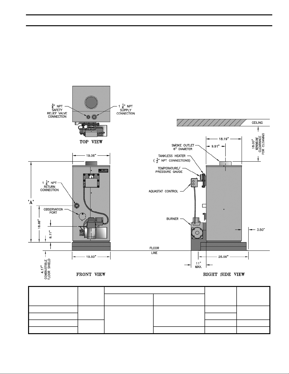
Table of Contents
I. Pre-Installation ....................................... 7
II. Knockdown Boiler Assembly ................ 9
III. Water Piping and Trim ......................... 12
IV. Venting .................................................18
V. Electrical and Sequence of Operation ..20
VI. Oil Piping .............................................
28
VII. System Start-Up ................................... 30
VIII. Service and Cleaning............................ 38
IX. Repair Parts ..........................................
40
X. Appendix
Low Water Cut Off ............................... 50
Boiler Model Number Dim. ‘A’
RSA85
RSA110 8.5
RSA125
RSA135 7 x 15 13.0 355
34¾
41¼
Figure 1: RSA Packaged Boiler (RSA85 / RSA135)
Minimum Recommended Chimney Sizes
In. x In. x Ft. (ht.) In. (dia.) x Ft. (ht.)
8 x 8 x 20
6 x 15
Water
Capacity
(gallons)
9.1
13.9 340
Weight (lb.)
Approx.
Shipping
300
5
Page 6
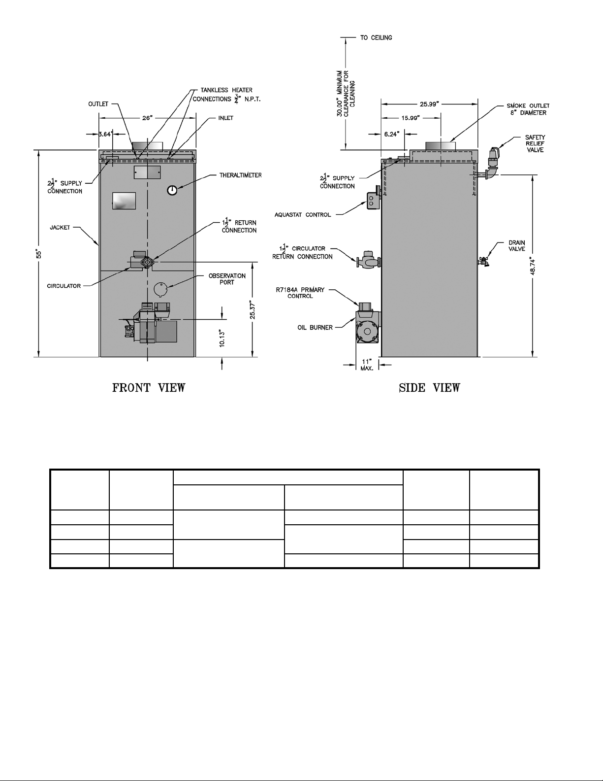
Figure 1A: RSA Packaged Boiler (RSA170 / RSA285)
Boiler
Model
Number
RSA170 WV-29-10
RSA195 WV-29-13A
RSA240 WV-29-16A
RSA285 WV-29-19A 9 x 20 34.6 690
Bare Boiler
Assembly
Minimum Recommended Chimney Sizes
In. x In. x Ft. (height) In. (dia.) x Ft. (height)
8 x 8 x 20
8 x 12 x 20
7 x 20 42.6 600
8 x 20
Water
Capacity
(gallons)
39.9 630
37.3 660
6
Approx.
Shipping
Weight (lb.)
Page 7

I. Pre-Installation
A. INSPECT SHIPMENT carefully for any signs of
damage.
1. ALL EQUIPMENT is carefully manufactured,
inspected and packed. Our responsibility ceases
upon delivery of the crated boiler to the carrier in
good condition.
2. ANY CLAIMS for damage or shortage of shipment
must led immediately against the carrier by
the consignee. No claims for variances from,
or shortage in orders, will be allowed by the
manufacturer unless presented within sixty (60) days
after receipt of goods.
B. LOCATE BOILER in front of nal position before
removing crate.
CAUTION
Do not drop boiler. Do not bump boiler jacket
against oor.
1. LOCATE so that smoke pipe connection to
chimney will be short and direct. BOILER IS
NOT SUITABLE FOR INSTALLATION ON
COMBUSTIBLE FLOOR unless combustible oor
shield, supplied by Burnham, is used. DO NOT
install on carpeting. See Figure 26 for oor shield
part number and installation instructions.
2. FOR BASEMENT INSTALLATION, provide a
solid base, such as concrete, if oor is not level, or if
water may be encountered on oor around boiler.
3. PROVIDE SERVICE CLEARANCE of at least 48”
from the front of the jacket for servicing of burner
and removal of tankless heater.
For minimum clearances to combustible materials. See
Figure 2.
WARNING
Do not support boiler by placing blocks at the
four (4) corners of the boiler.
Boiler base must be evenly supported under
entire base.
Do not operate boiler on combustible oor
without a factory supplie d floor shield.
Concrete over wood joists is considered
combust i b le floo r ing. D o not op erate
on ma s onry floors, which may contain
moisture.
Figure 2: Minimum Clearances to Combustible Materials
NOTE:
1. Listed clearances comply with American National Standard ANSI/NFPA 31, Installation of Oil Burning Equipment.
2. RSA™ boilers can be installed in rooms with clearances from combustible material as listed above. Listed clearances can not
be reduced for alcove or closet installations.
3. For reduced clearances to combustible material, protection must be provided as described in the above ANSI/NFPA 31
standard.
7
Page 8

C. PROVIDE COMBUSTION AND VENTILATION
AIR. Local code provisions may apply and should be
referenced.
WARNING
Adequate combustion and ventilation air must
be provided to assure proper combustion and
to maintain safe ambient air temperatures.
Do not install boiler where gasoline or other
ammable vapors or liquids, or sources of
hydrocarbons (i.e. bleaches, fabric softeners,
etc.) are used or stored.
1. Determine volume of space (boiler room). Rooms
communicating directly with the space in which
the appliances are installed, through openings not
furnished with doors, are considered a part of the
space.
Volume(ft3) = Length(ft) x Width(ft) x Height(ft)
2. Determine total input of all appliances in the space.
Add inputs of all appliances in the space and round
the result to the nearest 1000 BTU per hour.
3. Determine type of space. Divide Volume by total
input of all appliances in space. If the result is
greater than or equal to 50 ft3/1000 BTU per hour,
then it is considered an unconned space. If the
result is less than 50 ft3/1000 BTU per hour then the
space is considered a conned space.
4. For boiler located in an unconned space of a
conventionally constructed building, the fresh
air inltration through cracks around windows
and doors normally provides adequate air for
combustion and ventilation.
5. For boiler located in a conned space or an
unconned space in a building of unusually tight
construction, provide outdoor air with the use of two
permanent openings which communicate directly or
by duct with the outdoors or spaces (crawl or attic)
freely communicating with the outdoors. Locate one
opening within 12 inches of top of space. Locate
remaining opening within 12 inches of bottom of
space. Minimum dimension of air opening is 3
inches. Size each opening per following:
a. Direct communication with outdoors.
Minimum free area of 1 square inch per 4,000
BTU per hour input of all equipment in space.
Vertical ducts. Minimum free area of 1 square
b.
inch per 4,000 BTU per hour input of all
equipment in space. Duct cross-sectional area
shall be same as opening free area.
c. Horizontal ducts. Minimum free area of 1
square inch per 2,000 BTU per hour input of all
equipment in space. Duct cross-sectional area
shall be same as opening free area.
Alternate method for boiler located within
conned space. Use indoor air if two permanent
openings communicate directly with additional
space(s) of sufcient volume such that combined
volume of all spaces meet criteria for unconned
space. Size each opening for minimum free area
of 1 square inch per 1,000 BTU per hour input
of all equipment in spaces, but not less than 100
square inches.
6. Louvers and Grilles of Ventilation Ducts
a. All outside openings should be screened and
louvered. Screens used should not be smaller
than 1/4 inch mesh. Louvers will prevent the
entrance of rain and snow.
b. Free area requirements need to consider the
blocking effect of louvers, grilles, or screens
protecting the openings. If the free area of the
louver or grille is not known, assume wood
louvers have 20-25 percent free area and metal
louvers and grilles have 60-75 percent free area.
c. Louvers and grilles must be xed in the open
position, or interlocked with the equipment to
open automatically during equipment operation.
8
Page 9
II. Knock-Down Boiler Assembly
A. REMOVAL OF BOILER.
1. Remove, all boiler to skid, hold down fasteners.
Refer to Figure 3.
2. Carefully walk boiler to the edge of skid. Tilt the
boiler back, allowing an edge to rest on the oor,
and remove the skid.
Figure 3: Base on Skid
B. TEST HEAT EXCHANGER FOR LEAKS before
proceeding with jacket assembly. Heat exchanger,
canopy, and base are preassembled.
1. Install pressure gauge supplied, a hose to the city
water and a valve in the supply tapping. Plug
remainder of tappings.
2. Fill boiler with water and apply a pressure of at least
10 psig but no more than 30 psig.
WARNING
Do not apply more than 30 psig to boiler.
WARNING
Any combustion chamber which was damaged
must be replaced immediately.
CAUTION
If heat exchanger is not square on base DO NOT
twist. Carefully lift and reposition.
WARNING
Do not assemble boiler without cerafelt gaskets
between heat exchanger and combustion
chamber. Gaskets must also be between canopy
and heat exchanger.
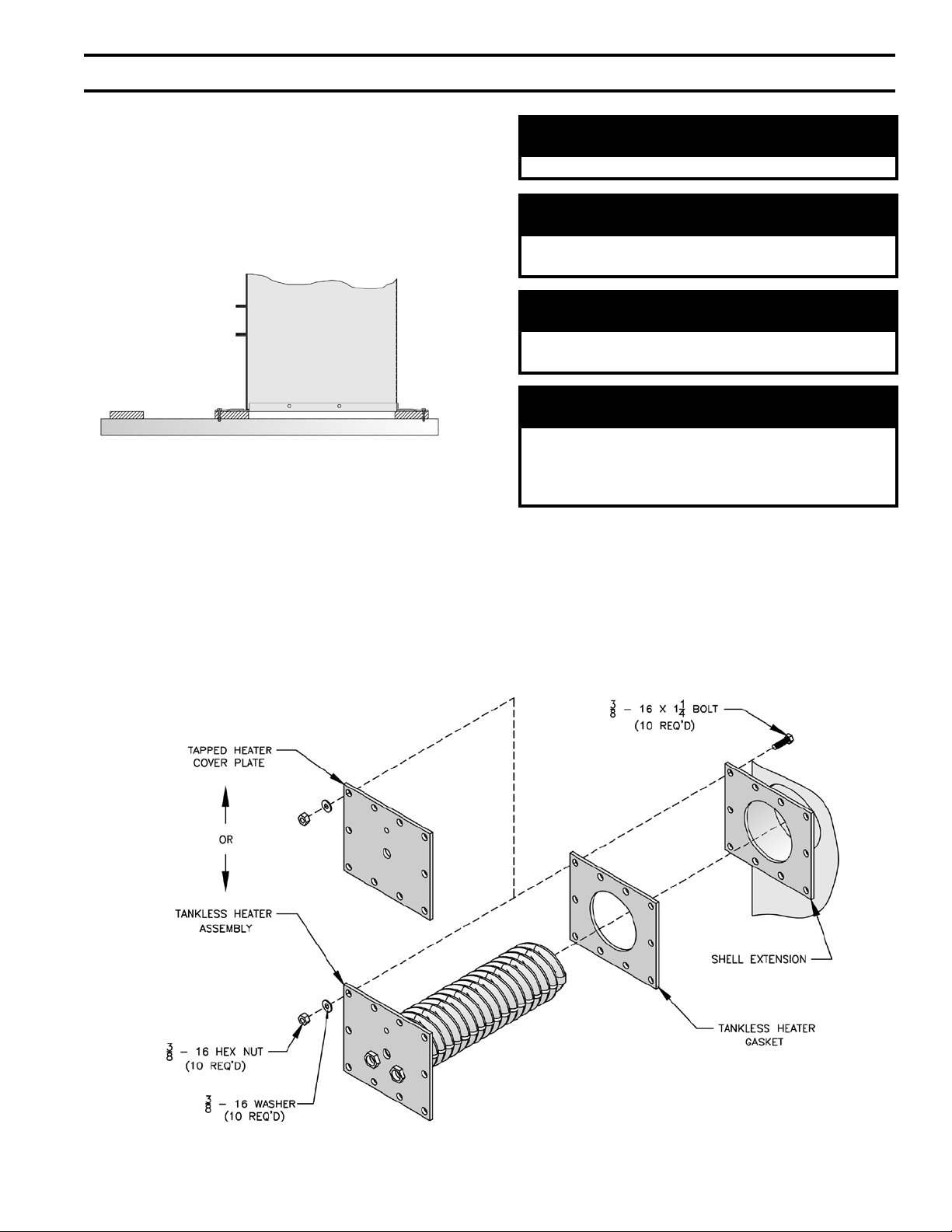
C. INSTALLING THE JACKET
1. Before jacket can be secured to boiler assembly
tankless heater coil or blank plate must be attached.
Using rubber gasket and bolts provided secure
heater coil or blank plate to boiler extension
by inserting the bolts from the backside of the
extension. Refer to Figure 4.
Figure 4: Coil Plate Attachment
9
Page 10
2. Bend jacket according to Figure 28. Starting
from the front, wrap the jacket around the boiler.
Make sure that return pipe, observation port and
shell extension t proper into there corresponding
clearance holes. Continue bending jacket around
until front panels meet.
3. Attach jacket to boiler assembly with provided
screws at appropriate locations. Make sure that the
jacket is at least ½” to ¾” off of the oor before
attaching.
4. Attach top panel with provided screws.
D. INSTALLATION OF BOILER CONTROLS
1. Install provided pressure/temperature gauge and
immersion well into appropriate holes on tankless
heater coil plate. Tighten so not to have any water
leaks.
2. Mount the aquastat control onto the immersion well.
Wire the control according to Figure 13 or 14, in the
Electrical and Sequence of Operation Section.
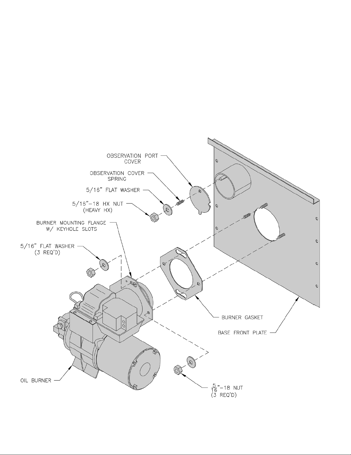
3. Mount burner on Base front panel and wire
according to instructions provided with the burner.
Refer to Figure 5.
10
Figure 5: Burner Mounting
Page 11

THIS PAGE IS LEFT INTENTIONALLY BLANK
11
Page 12
III. Water Piping and Trim
WARNING
Failure to properly pipe boiler may result in improper operation and damage to boiler or structure.
Oxygen contamination of boiler water will cause corrosion of iron and steel boiler components, and
can lead to boiler failure. Burnham’s Standard Warranty does not cover problems caused by oxygen
contamination of boiler water or scale (lime) build-up caused by frequent addition of water.
A. Design a piping system and install boiler which will
prevent oxygen contamination of boiler water and
frequent water additions.
1. There are many possible causes of oxygen
contamination such as:
a. Addition of excessive make-up water as a result
of system leaks.
b. Absorption through open tanks and ttings.
c. Oxygen permeable materials in the distribution
system.
2. In order to insure long product life, oxygen sources
should be eliminated. This can be accomplished by
taking the following measures:
a. Repairing system leaks to eliminate the need for
addition of make-up water.
b. Eliminating open tanks from the system.
c. Eliminating and/or repairing ttings which allow
oxygen absorption.
d. Use of non-permeable materials in the
distribution system.
e. Isolating the boiler from the system water by
installing a heat exchanger.
WARNING
System supply and return piping must be
connected to correct boiler pipe.
Burnham recommends sizing the system
circulator to supply sufcient ow (GPM) to
allow a 20°F temperature differential in the
system. When sizing the system circulator,
the pressure drop of all radiators, baseboard
and radiant tubing and all connecting piping
must be considered.
3. Connect System supply and return piping to
boiler. See Figures 8 and 9. Also, consult
I=B=R Installation and Piping Guides. Maintain
minimum ½ inch clearance from hot water piping to
combustible materials.
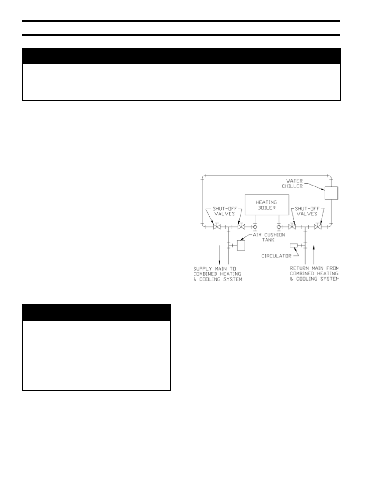
a. If this boiler is used in connection with
refrigeration systems, the boiler must be installed
so that the chilled medium is piped in parallel
with the heating boiler using appropriate valves
to prevent the chilled medium from entering
the boiler. See Figure 7. Also, consult I=B=R
Installation and Piping Guides.
Figure 7: Recommended Piping for Combination
Heating and Cooling (Refrigeration) System
b. If this boiler is connected to heating coils located
in air handling units where they may be exposed
to refrigerated air, the boiler piping must be
equipped with ow control valves to prevent
gravity circulation of boiler water during the
operation of the cooling system.
c. If boiler is used with an Alliance™ Indirect-Fired
Domestic Water Heater, install the Alliance™ as
a separate heating zone. Refer to the Alliance™
Installation, Operating, and Service Instructions
for additional information.
d. Use a system bypass if the boiler is to be
operated in a system which has a large volume
or excessive radiation where low boiler water
temperatures may be encountered (i.e. converted
gravity circulation system, etc.) The bypass
should be the same size as the supply and
return lines with valves located in the bypass
12
Page 13

and return line as illustrated in Figures 8 and 9
in order to regulate water ow for maintenance
of higher boiler water temperature. Set the
bypass and return valves to a half throttle
position to start. Operate boiler until the system
water temperature reaches its normal operating
range. Adjust the valves to maintain 180°F to
200°F boiler water temperature and greater the
120°F return temperature. Adjust both valves
simultaneously. Closing the boiler return valve
while opening the bypass valve will raise the
boiler return temperature. Opening the boiler
return valve while closing the by-pass valve will
lower the boiler return temperature.
e. A water boiler installed above radiation level
must be provided with a low water cutoff device
as part of the installation.
If a low water cut-off is required, it must be
mounted in the system piping above the boiler.
The minimum safe water level of a hot water
boiler is just above the highest water containing
cavity of the boiler; that is, a hot water boiler
must be full of water to operate safely.
B. Install Safety Relief Valve. See Figures 8 and 9.
Safety Relief Valve must be installed with spindle in
the vertical position. Installation of the relief valve
must be consistent with ANSI/ASME Boiler and
Pressure Vessel Code, Section IV.
WARNING
Safety (relief) valve discharge piping must be
piped near oor to eliminate potential of severe
burns. Do not pipe in any area where freezing
could occur. Do not install any shut-off valves,
plugs or caps.
C. Install Drain Valve in return piping. See Figures 8 and
9.
D. Oil, grease, and other foreign materials which
accumulate in new hot water and a new or reworked
system should be boiled out, and then thoroughly
ushed. A qualied water treatment chemical specialist
should be consulted for recommendations regarding
appropriate chemical compounds and concentrations
which are compatible with local environmental
regulations.
E. After the boiler and system have been cleaned and
ushed, and before relling the entire system add
appropriate water treatment chemicals, if necessary, to
bring the pH between 7 and 11.
WARNING
Installation is not complete unless a safety relief valve is installed as shown in Figure 1 or 1A.
13
Page 14
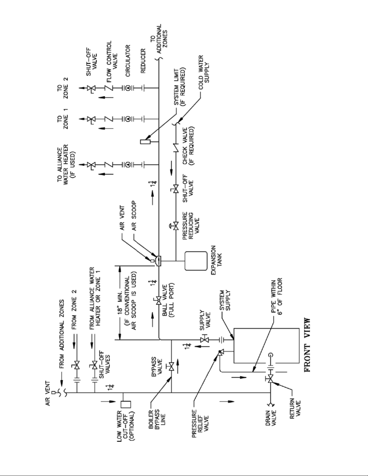
14
Figure 8: Recommended Water Piping for Circulator Zoned Heating Systems
Page 15
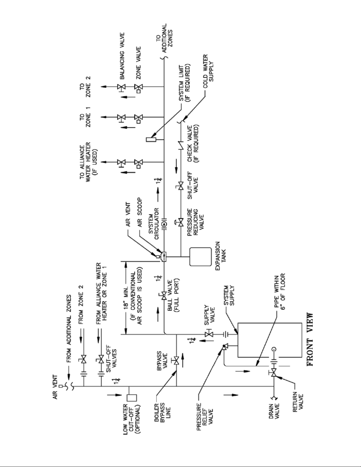
Figure 9: Recommended Water Piping for Zone Valve Zoned Heating Systems
15
Page 16

F. CONNECT TANKLESS HEATER PIPING AS
SHOWN IN FIGURE 10. See Table 1 for Tankless
Heater Rating.
WARNING
Install automatic mixing valve at tankless heater
outlet to avoid risk of burns or scalding due to
excessively hot water at xtures. Adjust and
maintain the mixing valve in accordance with
the manufacturer's instructions. Do not operate
tankless heater without mixing valve.
THE FOLLOWING GUIDELINES SHOULD BE
FOLLOWED WHEN PIPING THE TANKLESS HEATER:
1. FLOW REGULATION — If ow through the heater
is greater than its rating, the supply of adequate hot
water may not be able to keep up with the demand.
For this reason a ow regulator matching the heater
rating should be installed in the cold water line to
the heater. The ow regulator should preferably be
located below the inlet to the heater and a minimum
of 3’ away from the inlet so that the regulator is not
subjected to excess temperatures that may occur
during “off” periods when it is possible for heat
to be conducted back through the supply line. The
ow regulator also limits the ow of supply water
regardless of inlet pressure variations in the range of
20 to 125 psi.
2. TEMPERING OF HOT WATER — Installation of
an automatic mixing valve will lengthen the delivery
of the available hot water by mixing some cold
water with the hot. This prevents the possibility
of scalding hot water at the xtures. In addition,
savings of hot water will be achieved since the user
will not waste as much hot water while seeking a
water temperature. Higher temperature hot water
required by dishwashers and automatic washers is
possible by piping the hot water from the heater
prior to entering the mixing valve. The mixing valve
should be “trapped” by installing it below the cold
water inlet to heater to prevent lime formation in the
valve. Refer to Figure 10.
3. FLUSHING OF HEATER — All water contains
some sediment which settles on the inside of the
coil. Consequently, the heater should be periodically
backwashed. This is accomplished by installing
hose bibs as illustrated and allowing water at city
pressure to run into hose bib A, through the heater,
and out hose bib B until the discharge is clear. The
tees in which the hose bibs are located should be
the same size as heater connections to minimize
pressure drop.
4. HARD WATER — A water analysis is necessary to
determine the hardness of your potable water. This
is applicable to some city water and particularly to
well water. An appropriate water softener should
be installed based on the analysis and dealer’s
recommendation. This is not only benecial to the
tankless heater but to piping and xtures plus the
many other benets derived from soft water.
16
Page 17

Figure 10: Schematic Tankless Heater Piping
Table 1: Tankless Heater Ratings
Boiler Model
RSA85 & 110 3 12 3½ 15
RSA110, 125 & 135 3¼ 16
RSA125 & 135 3½ 19
Boiler Model
RSA170 3¾ 25½ 4 26½
RSA195, 240 & 285 4 29 4¼ 31
GPM PSID GPM PSID
GPM PSID GPM PSID
S350 S375
3¾ 25
STD. #7524 OPT. #7530
17
Page 18

IV. Venting
A. General Guidelines.
1. Vent system installation must be in accordance
with these instructions and applicable provisions of
local building codes. Contact local building or re
ofcials about restrictions and installation inspection
in your area.
2. The RSA Series is designed to be vented into a
reclay tile-lined masonry chimney or chimney
constructed from type-L vent or a factory
built chimney that complies with the type HT
requirements of UL103. The chimney or vent pipe
shall have a sufcient draft at all times, to assure
safe proper operation of the boiler. See Figure 11 for
recommended installation.
a. Install a draft regulator (supplied by installer)
following the instructions furnished with the
regulator. See Figure 12 for alternate regulator
locations.
b. With any new or replacement installation the
chimney has to be considered. Chimneys that
have a high heat loss become less suitable as
the heat loss of the home goes down and the
efciency of the boiler goes up. Most homes
have a chimney appropriate for the fuel and
the era in which the home was built. That may
have been a coal red or an inefcient oil red
boiler built into a home without insulation or
storm windows. With increasing fuel prices that
home probably has been insulated and tted with
storm windows so that the heat loss of the home
has been reduced. This requires less fuel to be
burned and sends less heat up the chimney.
A new boiler probably has a higher efciency
than the boiler being replaced. That probably
means that the stack temperature from the
new boiler will be lower than that from the
old boiler and with less room air being drawn
up the chimney to dilute the stack gases. The
combination of a large uninsulated chimney,
reduced ring rate, reduced ring time, lower
stack temperature and less dilution air can, in
some cases, contribute to the condensing of small
amounts of water vapor in the chimney. Such
condensation, when it occurs, can cause chimney
deterioration. In extreme cases, the chimney
may have to be lined to insulate the chimney and
thus prevent the condensation. The addition of
dilution air into the chimney may assist in drying
the chimney interior surfaces.
A massive chimney on a cold, or exposed outside
wall may have produced adequate draft when it
was red with a higher input and greater volumes
of heated gases. With reduced input and volume,
the draft may be severely affected. In one
instance our research showed a new chimney of
adequate sizing produced only -.035” W.C. after
30 minutes of continuous ring at 13.0% CO2.
Outside wall chimneys take longer to heat up and
can have .00” W.C. draft at burner start-up. You
may have to consider a special alloy chimney
ue liner with insulation around it and stabilizing
draft cap or even a draft inducing fan in severe
cases.
c. For the same reasons as in (2.) above, heat
extractors mounted into the breeching are not
recommended.
3. For minimum clearances to combustible materials
refer to Figure 2.
18
Page 19
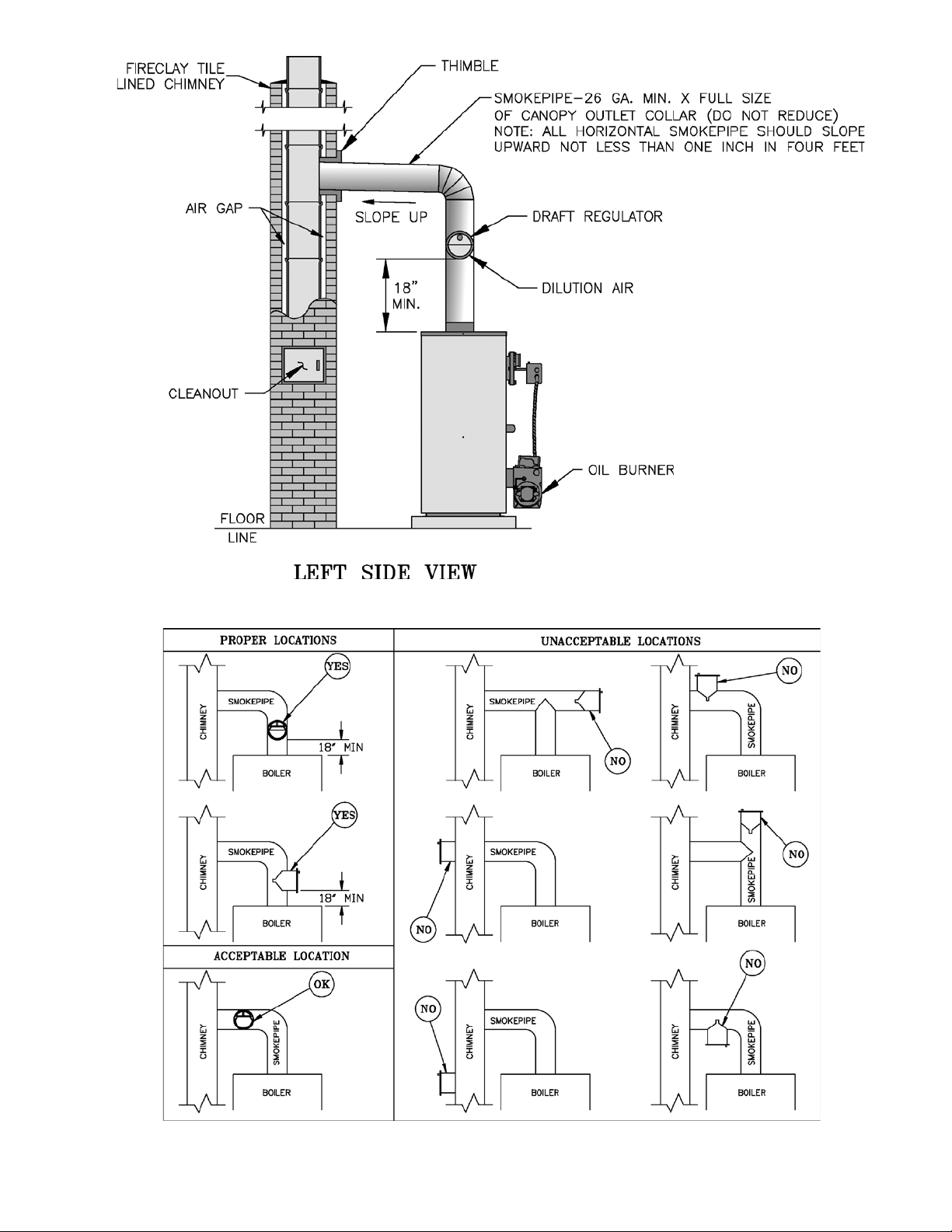
Figure 11: Recommended Smoke Pipe Arrangement and Chimney Requirements
Figure 12: Draft Regulator Locations
19
Page 20

V. Electrical
DANGER
Positively assure all electrical connections are unpowered before attempting installation or service of
electrical components or connections of the boiler or building. Lock out all electrical boxes with padlock
once power is turned off.
WARNING
Failure to properly wire electrical connections to the boiler may result in serious physical harm.
Electrical power may be from more than one source. Make sure all power is off before attempting any
electrical work.
Each boiler must be protected with a properly sized fused disconnect.
Never jump out or make inoperative any safety or operating controls.
The wiring diagrams contained in this manual are for reference purposes only. Refer to the wiring diagram
of any controls used with the boiler. Read, understand and follow all wiring instructions supplied with
the controls.
A. General
1. Install wiring and electrically ground boiler in
accordance with requirements of the authority
having jurisdiction, or in absence of such
requirements the National Electrical Code, ANSI/
NFPA 70, and/or the CSA C22.1 Electric Code.
2. A separate electrical circuit must be run from
the main electrical service with an over-current
device/disconnect in the circuit. A service switch is
recommended and may be required by some local
jurisdictions.
3. Wiring should conform to Figure 13 and/or 14.
B. System Controls and Wiring
1. Refer to National Electric Code or Local Electric
Codes for proper size and type of wire required.
Follow Code.
2. Use anti-short bushings on all wiring passing
through boiler jacket, junction boxes and/or control
boxes.
3. Use armored cable (BX) over all exposed line
voltage wiring.
4. If an Alliance indirect water heater is used, use
priority zoning. Do not use priority zoning for
Hydro-Air Systems.
5. Single Zone System – Refer to Figure 13 or 14 of
this manual for the electrical diagram for this type
of system. Connect the system circulator wire leads
to the proper locations on the Aquastat control,
L7224C/L7248C.
Connect the thermostat to the ‘T-T’ terminals on
the L7224C/L7248C control. Set thermostat heat
anticipator settings to 0.60 amps.
6. Conventional Circulator Zoned System – Refer to
Figure 15 for the electrical diagram for this type of
system.
Read, understand and follow all of the instructions
provided with the Honeywell R8888 control.
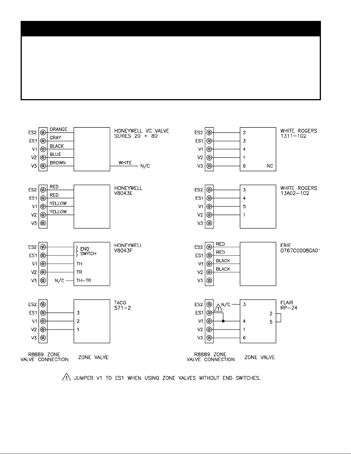
7. Conventional Zone Valve Zoned System – Refer
to Figure 16. Wiring to the most popular models of
zone valves are given in Figure 17.
Locate C1 and C2 inside the L7224C Honeywell
control. Connect the two (2) terminals to the system
circulator wire leads, supplied with boiler.
Connect the H1 and H2 terminals inside the R8889
to the ‘T-T’ terminals in the L7224C Honeywell
Control. Refer to Figure 16.
Connect the thermostat of each zone and the
circulator for that zone to R8889 panel. If an
Alliance indirect water heater is used, connect the
Alliance thermostat and circulator to the Zone 1
terminals of the R8889. Set thermostat anticipator
settings to 0.12 amps.
20
Page 21

Figure 13: “RSAL” Wiring Less Tankless, Single Circulator
Sequence of Operation
A call for heat by the thermostat energizes the L7224C/L7248C control which in turn energizes the Honeywell R4184D primary control to turn
on the burner. If burner ignites within approximately 45 seconds and the cad cell sees ame, the burner will continue to operate until the call for
heat is satised or the setting of the high limit is reached. The circulator will operate as long as the thermostat is calling for heat. If the thermostat is not satised and the high limit is reached, the circulator will continue to operate, and the burner will stop until the high limit is closed by a
drop in water temperature.
Figure 14: “RSAT” or “RSAR” Wiring with Tankless, Single Circulator
Sequence of Operation
A call for heat by the thermostat energizes the L7224C/L7248C control which in turn energizes the Honeywell R4184D primary control to turn
on the burner. If burner ignites within approximately 45 seconds and the cad cell sees ame the burner will continue to operate until the call for
heat is satised. The circulator will also operate when the thermostat calls for heat if the boiler water temperature is up to the setting of the low
limit in the L8124C control. If boiler water temperature is below the low limit setting the burner will operate but the circulator will not, giving
preference to the domestic hot water demand.
On call for heat by the thermostat the burner will continue to operate until the thermostat is satised or the setting of the high limit is reached. If
the thermostat is not satised when the high limit is reached the burner will stop but the circulator will continue to operate until the thermostat is
satised. Any time the boiler water temperature drops below the setting of the low limit the burner will be energized in order to maintain domes-
tic water temperature.
21
Page 22

22
Figure 15: Circulator Zoned Wiring for Honeywell R8888
Page 23
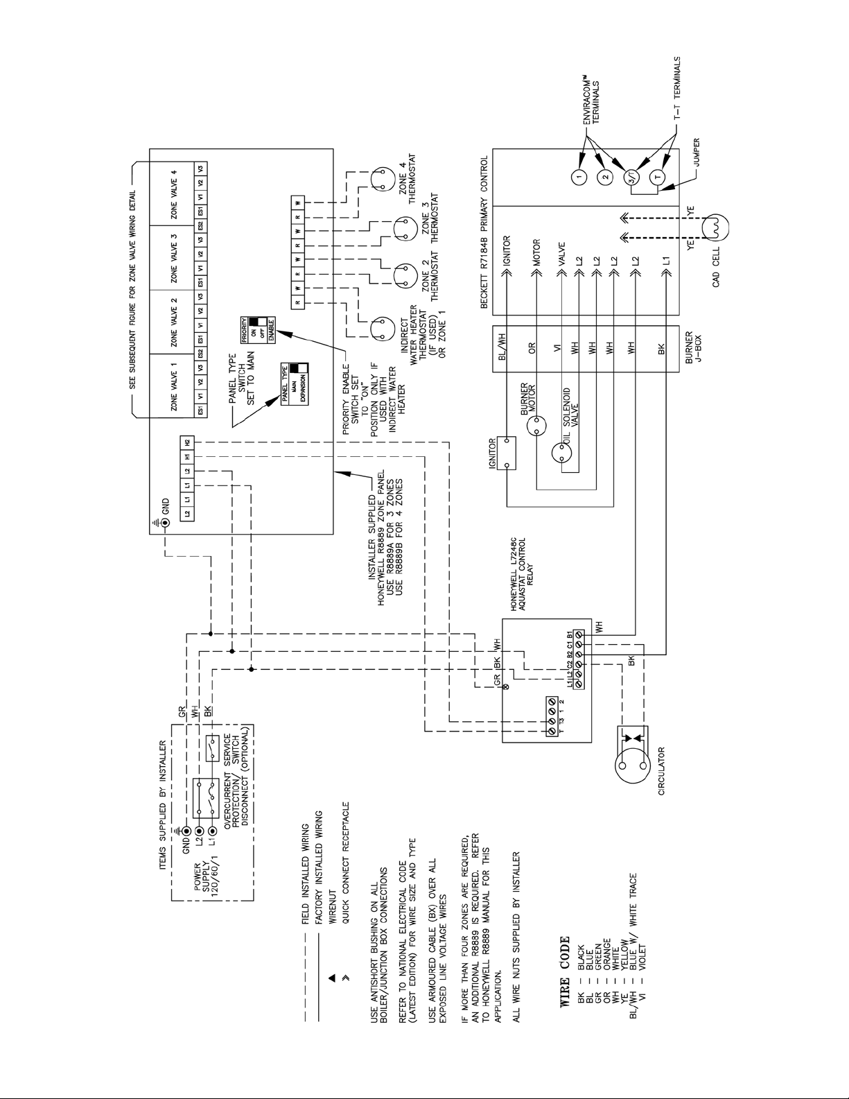
Figure 16: Zone Valve Zoned Wiring for R8889
23
Page 24
NOTICE
The Honeywell R8889 Control is available in two three (3) zone models and two four (4) zone models. Burnham
recommends using Model R8889A for three (3) zone systems and Model R8889B for four (4) zone systems.
Models R8889C and R8889D have less load capacity and may not operate with certain types of zone valves.
Up to four (4) R8889’s may be used together to provide up to sixteen (16) individual zones. Only one (1) zone,
the rst zone of the main control will provide priority zoning for the Alliance indirect water heater. If more
than four (4) zones are required, connect additional R8889’s by wiring the A, B and C terminals of each control
together. Each R8889 requires a 120 volt power supply. If more than one (1) R8889 is used, set the panel
type switch to “main” on the rst R8889 and set the panel type switch to “expansion” on the second, third or
fourth R8889.
24
Figure 17: Different Manufacturer’s Zone Valve Connections to Honeywell R8889
Page 25

NOTICE
The Burnham EC5000 Control includes a water temperature sensor. Mount this sensor to the system supply
piping.
8. Burnham EC5000 Circulator Zoned System – Refer
to Figure 18 of this manual for the electrical diagram
for this type of system. Wire the system as indicated
in that diagram. Refer to the manual provided with
the Burnham EC5000 Control for control operation
and setup details.
9. Burnham EC5000 Zone Valve Zoned System
– Refer to Figure 19 of this manual for the electrical
diagram for this type of system. Wire the system
as indicated in that diagram. Refer to the manual
provided with the Burnham EC5000 for control
operation and setup details.
25
Page 26

26
Figure 18: Circulator Zoning with EC5000 Wiring Schematic
Page 27

Figure 19: Zone Valve Zoned with EC5000 Wiring Schematic
27
Page 28

VI. Oil Piping
A. General.
1. Use exible oil line(s) so that burner can be
removed without disconnecting the oil supply.
2. A supply line fuel oil lter is recommended as a
minimum for all ring rates but a pleated paper fuel
oil lter is recommended for the lowest ring rate
application to prevent nozzle fouling.
3. Use Flared ttings only. Do not use compression
ttings.
4. Use of a high efciency micron lter (Garber or
equivalent) in addition to conventional lter is
highly recommended.
B. Single-pipe Oil Lines.
1. Standard burners are provided with single-stage
3450 rpm fuel units with the bypass plug removed
for single-pipe installations.
2. The single-stage fuel unit may be installed singlepipe with gravity feed or lift. Maximum allowable
lift is 8 feet. See Figure 20.
NOTICE
Oil piping must be absolutely airtight or leaks or
loss of prime may result. Bleed line and fuel unit
completely.
28
Figure 20: Single-Pipe Installation
Page 29

Table 2: Single-Stage Units (3450 RPM) -
Two Pipe Systems
Table 3: Two-Stage Units (3450 RPM) -
Two Pipe Systems
Maximum Length of Tubing
Lift "H"
(See Figure 21)
"H" + "R" (See Figure 21)
3/8" OD Tubing
(3 GPH)
0' 84' 100'
1' 78' 100'
2' 73' 100'
3' 68' 100'
4' 63' 100'
5' 57' 100'
6' 52' 100'
7' 47' 100'
8' 42' 100'
9' 36' 100'
10' 31' 100'
11' 26' 100'
12' 21' 83'
13' --- 62'
14' --- 41'
1/2" OD Tubing
(3 GPH)
Maximum Length of Tubing
Lift "H"
(See Figure 21)
0' 93' 100'
2' 85' 100'
4' 77' 100'
6' 69' 100'
8' 60' 100'
10' 52' 100'
12' 44' 100'
14' 36' 100'
16' 27' 100'
18' --- 76'
"H" + "R" (See Figure 21)
3/8" OD Tubing
1/2" OD Tubing
(3 GPH)
(3 GPH)
C. Two-Pipe Oil Lines
1. For two-piped systems, where more lift is required,
the two-stage fuel unit is recommended. Table
2 (single-stage) and Table 3 (two-stage) show
allowable lift and lengths of 3/8 inch and 1/2 inch
OD tubing for both suction and return lines. Refer
to Figure 21.
Figure 21: Two-Pipe Installation
29
Page 30

VII. System Start-Up
A. Verify that the venting, water piping, oil piping, and
electrical system are installed properly. Refer to
installation instructions contained in this manual.
B. Conrm all electrical, water and oil supplies are
turned off at the source and that the vent is clear from
obstructions.
WARNING
Completely read, understand and follow all
instructions in this manual before attempting
start up.
C. Fill entire heating system with water and vent air from
system. Use the following procedure on a Series Loop
or multi-zoned system installed as per Figure 8 or 9.
1. Close isolation valve in boiler supply piping.
2. Isolate all circuits by closing zone valves or
balancing valves.
3. Attach a hose to hose bib located just below
isolation valve in boiler supply piping. (Note
- Terminate hose at a suitable oor drain or outdoor
area).
4. Starting with one circuit at a time, open zone valve
or valve.
5. Open hose bib.
6. Open ll valve (Make-up water line should be
located directly after isolation valve in boiler supply
piping between air scoop and expansion tank).
7. Allow water to ow into drain until discharge from
hose is bubble free for 30 seconds.
8. When zone is completely purged of air, close zone
valve or balancing valve. Open the zone valve for
the next zone to be purged. Repeat this step until
all zones have been purged. At completion, open all
zone valves or valves.
WARNING
The maximum operating pressure of this boiler is
30 psig. Never exceed this pressure. Do not plug
or change pressure relief valve.
9. Close hose bib, continue lling the system until the
pressure gauge reads 12 psig. Close ll valve.
(Note - If make-up water line is equipped with
pressure reducing valve, system will automatically
ll to 12 psig.
10. Open isolation valve in boiler supply piping.
11. Remove hose from hose bib.
D. CONFIRM that the boiler and system have no water
leaks.
E. CHECK CONTROLS, WIRING AND BURNER to
be sure that all connections are tight and burner is
rigid. Verify that all electrical connections have been
completed, fuses installed, that the oil tank is lled and
oil lines have been tested.
F. LUBRICATION. Follow instruction on burner and
circulator label to lubricate, if oil lubricated. Most
motors currently used on residential type burners
employ permanently lubricated bearings and thus do
not require any eld lubrication. Water lubricated
circulators do not need eld lubrication.
G. ADJUST CONTROL SETTINGS with burner service
switch turned “ON”.
1. SET ROOM THERMOSTAT about 10°F below
room temperature.
2. PRESS RED RESET BUTTON on R7184B Oil
Primary Control and release.
3. On BOILERS WITHOUT TANKLESS HEATERS
equipped with L7248 electronic aquastat controller,
set High Limit (HL) at 180°F. This temperature can
be varied to suit installation requirements. L7248
controller has the High Limit adjustment range
from 180°F to 240°F (82°C to 116°C). High Limit
Differential is xed at 15°F (8°C).
4. On BOILERS WITH TANKLESS HEATERS
equipped with L7224 electronic aquastat controller,
set operating control (low limit [LL]) at 190°F and
high limit (HL) at 210°F. Operating control (low
limit) setting must be a minimum of 20°F below
high limit setting.
L7224 controller has the High Limit adjustment
range from 130°F to 240°F (55°C to 116°C), and
the Low Limit adjustment range from 110°F to
220°F (43°C to 104°C). High Limit Differential is
xed at 10°F (6°C), and Low Limit Differential has
adjustment range from 10°F (6°C) to 25°F (14°C).
5. ADJUSTING AQUASTAT CONTROLLER
SETTINGS. To discourage unauthorized changing
of Aquastat settings, a procedure to enter the
ADJUSTMENT mode is required. To enter the
ADJUSTMENT mode, press the UP, DOWN, and
I buttons (refer to Figure 22) simultaneously for
three seconds. Press the I button until the feature
requiring adjustment is displayed:
• HL_ High Limit.
• LL_ Low Limit.
• Ldf Low Limit Differential.
• °F °C.
30
Page 31

Figure 22: L7248/L7224 Circuit Board Layout -
Horizontal Mount
Then, press the UP and/or DOWN buttons to
move the set point to the desired value. After 60
seconds without any button inputs, the control will
automatically return to the RUN mode.
Note that L7224 Aquastat Controller will display all
four (4) above-listed adjustment features, but L7248
Aquastat Controller will not display Low Limit and
Low Limit Differential adjustment features.
6. DISPLAY READOUT
In the RUN mode, the Aquastat will ash "bt"
(boiler temp) followed by the temperature (i.e.,
220), followed by °F or °C.
To read boiler settings, press the I key to read the
parameter of interest. For example, press I High
Limit (HL) is displayed, followed by a three-digit
number, i.e., 220, followed by °F or °C. Pressing
the I button again (on L7224 models) will display
the Low Limit (LL) followed by a three-digit
number and the corresponding degree designator.
See Display Readout, Figure 23.
After approximately 60 seconds without any key
presses, the display will enter a dim display mode.
To return to the bright display mode, simply press
any key.
7. OPERATION
The L7224 model can be in any of four operational
states - Normal, High Limit, Low Limit and Error.
The controller moves back and forth from High
Limit to Normal to Low Limit state as part of
normal operation.
The L7248 model is restricted to three operational
states - Normal, High Limit and Error. The
controller moves back and forth from High Limit to
Normal state as part of normal operation.
For both models, the controller will enter the Error
state when there is an abnormal condition. The
operating states are:
a. Normal: Boiler temperature went below the
High Limit setting (minus the Differential) and
has not exceeded the High Limit setting; or the
boiler temperature went above the Low Limit
setting and has not gone below the Low Limit
setting (minus the Differential).
b. High Limit: Boiler temperature went above the
High Limit setting and has not dropped below
the High Limit setting (minus the Differential).
c. Low Limit: Boiler temperature went below
the Low Limit setting (minus the Low Limit
Differential) and has not gone above the Low
Limit setting.
d. Error: The controller has detected an error
condition (e.g., open sensor) and has shut down
the burner output. The ZC output is energized.
The controller continues to monitor the system
and automatically restarts if the error condition
clears. Refer to Table 4.
Table 4: LED Error Codes
Error
Code
Err1 Sensor fault; check sensor.
Err2 ECOM fault; check EnviraCOM™ wiring.
Err3 Hardware fault; replace control.
Err4 B1 fault; check B1 wiring/voltage.
Err5 Low Line; check L1-L2, 110 Vac.
Err6 Fuse; check ECOM wires, replace fuse.
Err7
Err8
EEPROM, HL, LL, Hdf, Ldf; reset to default values.
Restore desired settings.
Repeated B1 fault (voltage present at B1 when output is turned off); check B1 wiring/voltage.
Cause / Action
Figure 23: Display Readout Denitions
The operating sequence for the L7224/L7248 is
shown in Table 5. See Table 6 for Trouble Shooting
Guide.
8. HIGH LIMIT CONTROLLER
The High Limit opens and turns off the burner
when the water temperature reaches the setpoint.
The High Limit automatically resets after the water
temperature drops past the setpoint and through the
31
Page 32

Table 5: L7224 / L7248 Controller
Operating Sequence
Action System Response
Thermostat
calls for heat.
Boiler exceeds
the High Limit.
Thermostat is
satised.
Error condition
1-5.
Error
condition 6.
Error
condition 7.
Error
condition 8.
Circulator starts when water temperature is
above Low Limit setting (if applicable). Boiler
temperature is checked. Burner starts when
water temperature is below High Limit setting.
Burner is turned off. Burner restarts when the
water temperature drops below the High Limit
setting minus the Differential.
Circulator and burner turn off.
If an error condition is detected, all outputs except ZC are shut down. Burner is off. Control
continues to function and restarts when error is
corrected.
During the error check sequence, the system
checks for drift in the sensor and corrosion in
the connections.
EnviraCOM communication is not available.
The control has reset the High Limit, Low Limit
and Differential setting to a default setting and
will continue to run at those settings.
Performance of the system will be degraded.
If the error condition is detected, all outputs
except ZC are shut down. Burner is off. Control
continues to function and restarts when all
three user keys have been pressed longer than
60 seconds.
9. LOW LIMIT AND CIRCULATOR CONTROLLER
On a temperature rise, with the adjustable
Differential at the default setting of 10°F (6°C),
the burner circuit breaks and the circulator circuit
makes (assuming no call for heat is present) at the
Low Limit setpoint. On a temperature drop of 10°F
(6°C) below the Low Limit setpoint, the burner
circuit makes and the circulator circuit breaks. See
Figure 24.
Differential. The L7248 models have High Limit
Differential presets of 15°F (8°C). The L7224
Figure 24: Setpoints and Differentials
models have High Limit Differential presets of 10°F
(6°C).
Table 6: Trouble Shooting Guide
System Condition Diagnostic Condition Check Action
Boiler is cold, house is
cold.
Boiler is hot, house is
cold.
Display is OFF. 120 Vac System power. Turn system power on.
Display is ON. 24 Vac T-T No 24 V; replace control.
24 V present; disconnect thermostat,
short T-T.
120 Vac at B1-B2 • If no, replace control.
Refer to Err on display. -----
Display is ON. 120 Vac at C1-C2 • 120 Vac at C1-C2, check wiring
Boiler below the Low Limit temperature, wait for boiler to go above Low
Limit temperature.
Boiler above LL? If yes, check for
120 Vac between ZC and L2.
Boiler starts, check wiring and thermostat.
• If yes, check burner and wiring.
to pump.
• Wiring OK, is pump running?
• If not, replace the pump.
• If pump is running, check for
trapped air or closed zone valves
-----
• If no 120 Vac , replace control.
• If yes, check zone relays, circulators
and wiring.
32
Page 33

Table 7: Beckett AFG, AF, & SF Burners
Boiler Model
RSA85* .85 .75 x 80B 10
RSA110 1.10 .90 x 80B 8
RSA125 1.25 1.0 x 80B 7
RSA135 1.35 1.10 x 80B 9
RSA170 1.70 1.65 x 80A 7
RSA195 1.95 2.00 x 80B 7
RSA240 2.40 2.50 x 80B 7
RSA285 2.85 3.00 x 80B 7
* Equipped with low ring rate bafe
Firing Rate
(GPH)
Hago Nozzle
Table 7A: Becket AFG Burner
Boiler Model
RSAH85 .75 .65 x 80B 6
RSAH110 1.0 .85 x 80B 7
RSAH125 1.1 .90 x 80B 7
RSAH135 1.25 1.0 x 80B 9
Firing Rate
(GPH)
Hago Nozzle
Air Settings
Shutter Band Head (stop screw) Pump Pressure
140
0 N/A
100
Air Settings
Shutter Band
0 N/A 140
Head
(stop screw)
Pump Pressure
Table 7B: Carlin EZ-2HP Burner
Boiler Model Firing Rate Manufacturer GPH Angle Type Head Bar Air Band Setting
RSA85 .85
RSAH85 .75 .65
RSA110 1.10 .90
RSAH110 1.00 .85 .60
RSA125 1.25 1.10
RSAH125 1.10 .90 .85/1.00 .65
RSA135 1.35 1.20 W
RSAH135 1.25 1.10 A .85
Delavan
.75
60°
A .75 .60
.60/.65 .50
W
.85/1.00
A
1.10/1.25 .90
1.10/1.25
.75
.85
Figure 25: Electrode / Head Setting for
Beckett Burner
Figure 25A: Electrode / Head Setting for
Carlin EZ-1HP Burner
33
Page 34

H. REMOVE GUN ASSEMBLY
1. Check nozzle size, head size, gun setting, and
positioning of electrodes. This information is shown
in Figure 25 and Tables 7 and 7A for Beckett burner,
Figure 25A and Table 7B for Carlin EZ-1HP burner.
2. Reinstall gun assembly.
I. VERIFY OIL BURNER SETTINGS BEFORE
STARTING
BURNER AIR BAND AND AIR SHUTTER
1.
SETTINGS, see Tables 7 and 7A for Beckett burner,
Table 7B for Carlin EZ-1HP burner.
2. OPEN ALL OIL LINE VALVES.
3. Attach a plastic hose to fuel pump vent tting and
provide a container to catch the oil.
4. REMOVE GAUGE PORT PLUG from fuel pump
and install pressure gauge.
J. START OIL BURNER
1. Open vent tting on fuel pump.
2. TURN ‘ON’ BURNER service switch and allow
burner to run until oil ows from vent tting
in a SOLID stream without air bubbles for
approximately 10 seconds.
3. Close vent tting and burner ame should start
immediately after pre-purge is complete. Pre-purge
prevents burner ame until 10 seconds has elapsed
after initial power is applied to burner. During
pre-purge, the motor and ignitor will operate but the
oil valve will remain closed. Refer to Oil Primary
Control Instructions for more details.
4. For Carlin burner, refer to “Installation and
Operating Instructions for Packaged Heating/
Burner Units, Carlin Elite Oil Burner” (Form
CCT-569A) for instructions for Bleeding the Pump
and Starting the Burner.
K. ADJUST OIL PRESSURE
1. Locate oil pressure adjusting screw and turn screw
until Pressure Gauge reads the correct pump
pressure required for the specic boiler. Refer to
Tables 7 & 7A for Beckett burners or Table 7B for
Carlin burner (set pump pressure to 150 for Carlin
EZ-1HP Burner).
2. DO NOT REMOVE PRESSURE GAUGE until
later.
2. ADJUST DRAFT REGULATOR for a draft of -
.02” (water gauge) over the re after chimney has
reached operating temperature and while burner is
running.
3. READJUST AIR BANDS on burner for a light
orange colored ame while draft over the re is
-.02” w.c. Use a smoke test and adjust air for
minimum smoke (not to exceed #1) with a minimum
of excess air. Make nal check using suitable
instrumentation to obtain a CO2 of 11.5 to 12.5%
with draft of -.02” w.c. in re box. These settings
will assure a safe and efcient operating condition.
If the ame appears stringy instead of a solid ame,
try another nozzle of the same type. Flame should
be solid and compact. After all adjustments have
been made, recheck for a draft of -.02” w.c. over the
re.
4. TURN “OFF” BURNER and remove pressure
gauge. Install gauge port plug and tighten. Start
burner again.
Carlin Burner
1-4. Refer to “Installation and Operating Instructions
for Packaged Heating/Burner Units, Carlin Elite
Oil Burner” (Form CCT-569A) for instructions for
Bleeding the Pump and Starting the Burner.
5. Turn “off” Burner and remove pressure gauge.
Install gauge port plug and tighten. Start burner
again.
6. CAD Cell Location and Service. The burner is
supplied with a cadmium sulde ame detector
mounted at the factory, mounted on the bottom of
the transformer. See “Installation and Operating
Instructions for Packaged Heating/Burner Units,
Carlin Elite Oil Burner” (Form CCT-569A). To
service cad cell or to replace the plug in portion,
swing open the transformer. After service is
complete, be sure to fasten down the transformer.
M. FLAME FAILURE
The RSA boiler controls operate the burner
automatically. If for unknown reasons the burner
ceases to re and the reset button on the primary control
has tripped, the burner has experienced ignition failure.
Before pressing the reset button, call your serviceman
immediately.
L. OTHER ADJUSTMENTS
Beckett Burner
1. ADJUST THE AIR BAND AND/OR AIR
SHUTTER.
a. Adjust air supply by loosening lock screws and
moving the air shutter and if necessary the air
band. Refer to Tables 7 and 7A preliminary
settings.
34
WARNING
Do not attempt to start the burner when excess oil
has accumulated, when the unit is full of vapor, or
when the combustion chamber is very hot.
N. CHECK FOR CLEAN CUT OFF OF BURNER
1. AIR IN THE OIL LINE between fuel unit and
Page 35

nozzle will compress when burner is on and will
expand when burner stops, causing oil to squirt from
nozzle at low pressure as burner slows down and
causing nozzle to drip after burner stops. Usually
cycling the burner operation about 5 to 10 times will
rid oil line of this air.
2. IF NOZZLE CONTINUES TO DRIP, repeat step
N.1. If this does not stop the dripping, remove cut
off valve and seat, and wipe both with a clean cloth
until clean. Then replace and readjust oil pressure.
If dripping or after burn persist replace fuel pump.
O. HINTS ON COMBUSTION
1. NOZZLES— Although the nozzle is a relatively
inexpensive device, its function is critical to the
successful operation of the oil burner. The selection
of the nozzle supplied with the RSA boiler is the
result of extensive testing to obtain the best ame
shape and efcient combustion. Other brands of
the same spray angle and spray pattern may be
used but may not perform at the expected level of
CO2 and smoke. Nozzles are delicate and should
be protected from dirt and abuse. Nozzles are mass
produced and can vary from sample to sample. For
all of those reasons a spare nozzle is a desirable item
for a serviceman to carry.
2. FLAME SHAPE — Looking into the combustion
chamber through the ame plug hole, the ame
should appear straight with no sparklers rolling up
toward the top of the chamber. If the ame drags to
the right or left, sends sparklers upward or makes
wet spots on the combustion chamber, the nozzle
should be replaced. If the condition persists look
for fuel leaks, air leaks, water or dirt in the fuel as
described below.
3. FUEL LEAKS— Any fuel leak between the
pump and the nozzle will be detrimental to good
combustion results. Look for wet surfaces in the air
tube, under the ignitor, and around the air inlet. Any
such leaks should be repaired as they may cause
erratic burning of the fuel and in the extreme case
may become a re hazard.
4. AIR LEAKS— Any such leaks should be repaired,
as they may cause erratic burning of the fuel and in
extreme cases may become a re hazard.
There may be many possible causes of leaks in oil
lines such as:
a. Fitting leaks due to misared tubing or damaged
tting.
b. Fuel line leak due to crushed or bent tubing.
c. Filter connection leaks.
d. Tank connection leaks.
The following actions can eliminate air leaks:
a. Bleed pump as detailed in System Start-Up
Section of this manual.
b. Replace are ttings.
c. Replace oil supply line.
d. Repair oil lter leaks
e. Replace or repair tank ttings.
5. GASKET LEAKS— If 11.5% to 12.5% CO2 with a
#1 smoke cannot be obtained in stack, look for air
leaks around the canopy seal. Such air leaks will
cause a lower CO2 reading in the stack. The smaller
the ring rate the greater effect an air leak can have
on CO2 readings.
6. DIRT— A fuel lter is a good investment.
Accidental accumulation of dirt in the fuel system
can clog the nozzle strainer and produce a poor
spray pattern from the nozzle.
7. WATER— Water in the fuel, in large amounts, will
stall the fuel pump. Water in the fuel pump, in
smaller amounts, will cause excessive wear on the
pump, but more importantly water does not burn.
It chills the ame, causes smoke, and allows un-
burned fuel to pass through the combustion chamber
and clog the ueways of the boiler.
NOTICE
CHECK TEST PROCEDURE. A very good test for
isolating fuel side problems is to disconnect the
fuel system and with a 24" length of tubing, re
out of an auxiliary ve gallon pail of clean, fresh,
warm #2 oil from another source. If the burner runs
successfully when drawing out of the auxiliary
pail then the problem is isolated to the fuel or fuel
lines being used on the jobsite.
8. COLD OIL— If the oil temperature approaching
the fuel pump is 40°F or lower, poor combustion
or delayed ignition may result. Cold oil is harder
to atomize at the nozzle. Thus, the spray droplets
get larger and the ame shape gets longer. An
outside fuel tank that is above grade or has fuel lines
buried in the ground above the frost line is a good
candidate for cold oil. The best solution is to place
the tank and oil lines in the ground below the frost
line.
9. HIGH ALTITUDE INSTALLATIONS
Typically, the rule to use for high altitudes is to
increase the air supply by 4% per each 1000 ft.
above 2000 ft. altitude from sea level. This means
that the air setting will have to be higher than the
calibration marks in proportion to the altitude. Use
instruments and set for 11.5 to 12.5% CO2.
10. START-UP NOISE — Late ignition is the cause of
start-up noises. If it occurs recheck for electrode
settings, ame shape, air or water in the fuel lines.
11. SHUT DOWN NOISE — If the ame runs out of
air before it runs out of fuel, an after burn with
noise may occur. That may be the result of a faulty
cut-off valve in the fuel pump, or it may be air
35
Page 36
trapped in the nozzle line. It may take several ring
cycles for that air to be fully vented through the
nozzle. Water in the fuel or poor ame shape can
also cause shut down noises.
P. TEST CONTROLS
WARNING
Before installation of the boiler is considered
complete, the operation of all boiler controls must
be checked, particularly the primary control and
high limit control.
1. CHECK THERMOSTAT OPERATION. Raise and
lower thermostat setting as required to start and stop
burner.
2. VERIFY PRIMARY CONTROL SAFETY
FEATURES using procedures outlined in
Instructions furnished with control (See back of
Control Cover) or Instructions as follows:
WARNING
Service of this boiler should be undertaken only
by trained and skilled personnel from a qualied
service agency.
Simulate ame failure:
a.
• Follow the starting procedure to turn on the
burner.
• Close the hand valve in the oil supply line.
• Control enters recycle mode and tries
to restart burner after approximately 60
seconds.
• Safety switch should lock out in
approximately 15 seconds. Ignition and
motor should stop.
• Indicator light will ash ½ second on,
½ second off.
• Push red reset button to reset safety switch.
b.
Simulate ignition failure:
• Follow the starting procedure to turn on the
burner, but do not open the oil supply hand
valve.
• Safety switch should lock out in
approximately 15 seconds. Ignition and
motor should stop.
• Indicator light will ash ½ second on,
½ second off.
• Push red reset button to reset safety switch.
c.
Simulate power failure:
• Follow the starting procedure to turn on the
burner.
• With the burner running, turn off the power
to the system by tripping the circuit breaker
or removing the fuse.
• Burner should stop.
• Restore power. Burner should start.
3. VERIFY HIGH LIMIT OPERATION.
a. Adjust thermostat to highest setting.
b. Observe temperature gauge. When temperature
is indicated, adjust limit to setting below
observed temperature. Burner should stop.
c. Adjust limit to setting above observed
temperature. Burner should start.
d. Adjust thermostat to lowest setting. Adjust limit
to desired setting.
4. CHECK LOW WATER CUTOFF (if so equipped).
a. Adjust thermostat to highest setting.
b. With boiler operating, open drain valve and
slowly drain boiler.
c. Burner should stop when water level drops
below low water cutoff probe. Verify limit,
thermostat or other controls have not shut off
boiler.
d. Adjust thermostat to lowest setting. Rell
boiler.
Q. Boiler is now ready to be put into service.
IMPORTANT
IF, DURING NORMAL OPERATION, IT IS
NECESSARY TO ADD WATER MORE FREQUENTLY
THAN ONCE A MONTH, CONSULT A QUALIFIED
SERVICE TECHN ICIAN TO CHECK YOUR
SYSTEM FOR LEAKS.
A leaky system will increase the volume of make-up
water supplied to the boiler which can signicantly
shorten the life of the boiler. Entrained in make-up
water are dissolved minerals and oxygen. When the
fresh, cool make-up water is heated in the boiler the
minerals fall out as sediment and the oxygen escapes
as a gas. Both can result in reduced boiler life. The
accumulation of sediment can eventually isolate the
water from contacting the steel. When this happens
the steel in that area gets extremely hot and eventually
cracks. The presence of free oxygen in the boiler creates
a corrosive atmosphere which, if the concentration
becomes high enough, can corrode the steel through
from the inside. Since neither of these failure types are
the result of a manufacturing defect the warranty does
not apply. Clearly it is in everyone’s best interest to
prevent this type of failure. The maintenance of system
integrity is the best method to achieve this.
36
Page 37
INSTALLATION INSTRUCTIONS FOR SHIELD REQUIRED FOR COMBUSTIBLE FLOOR
This shield for combustible oors is intended for use only with the following Burnham oil-red boilers:
Use Part Number 6183504 for the following models:
RSA85 RSA110 RSA125 RSA135
ADDS 4-3/16” TO BOILER HEIGHT
Use Part Number 6183505 for the following models:
RSA170 RSA195 RSA240 RSA285
ADDS 5-3/8” TO BOILER HEIGHT
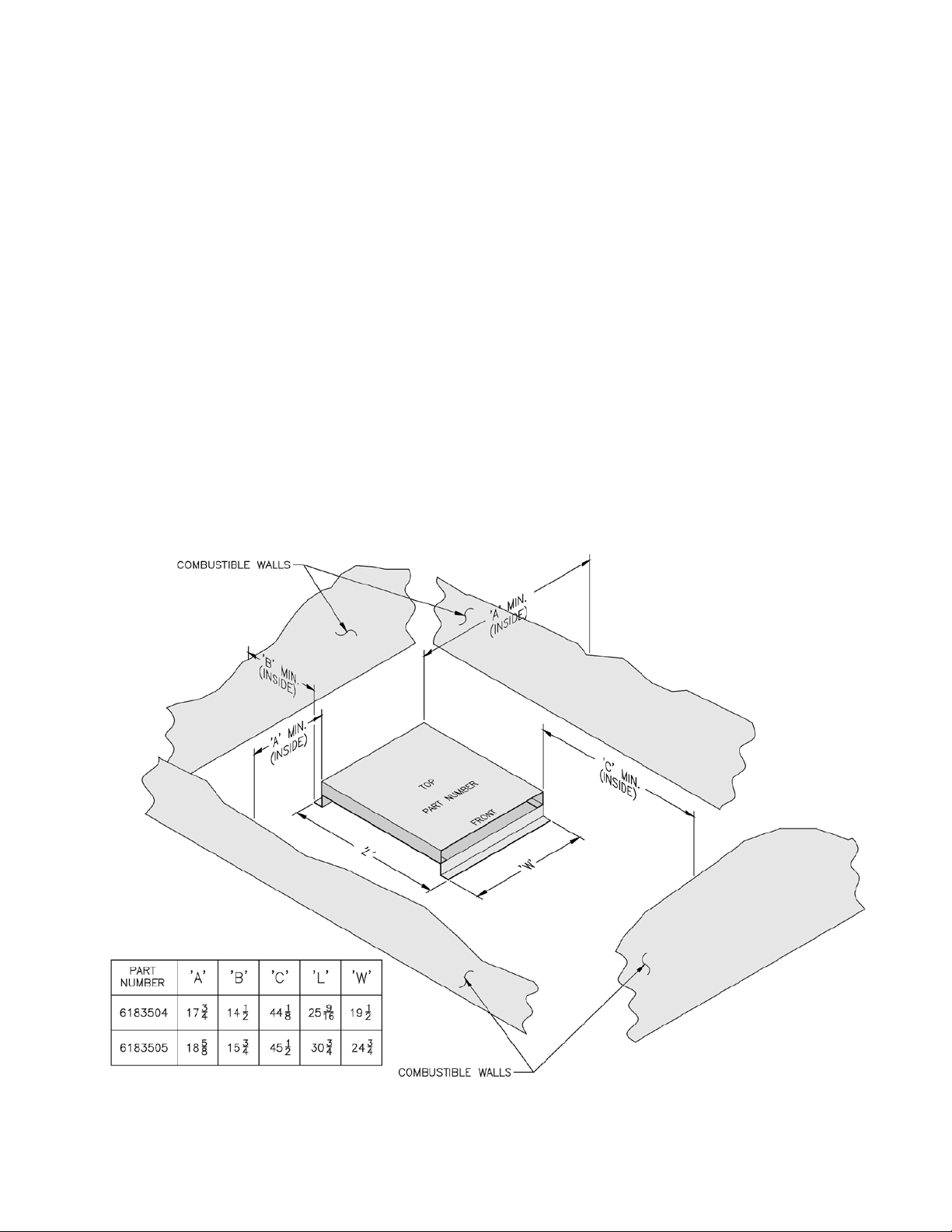
1) Place shield on combustible oor with “TOP” surface
upward and “FRONT” surface directly below the
expected position of the oil burner.
2) Locate shield such that clearances to combustible walls
are as indicated in Figure 26. These dimensions will
assure that the boiler jacket will be at least 18” from
the side and rear walls and 48” from the front wall, as
required by ANSI/NFPA 31.
3) Fasten shield to combustible oor to keep shield from
shifting position during setting of boiler.
4) Set boiler squarely on top of shield such that base plate
of boiler rests at on top surface of shield and does not
over-hang shield on any side. Conrm clearance to
combustible walls. Refer to Figure 2.
5) Do not enclose boiler (including shield) on all four
sides. Boiler may be enclosed on any three sides while
maintaining minimum clearances shown in Figure 2 for
each of those three sides.
Figure 26
37
Page 38
VIII. Service and Cleaning
NOTICE
BURNER SHUTDOWN: Open Service Switch
to turn off burner.
Manual Oil Supply Valve should be closed and
Electric Service to boiler turned off if boiler
will not be operated for an extended period
of time.
A. General. Inspection service and cleaning should be
conducted annually. Turn off electric power and
close oil supply valve while conducting service or
maintenance.
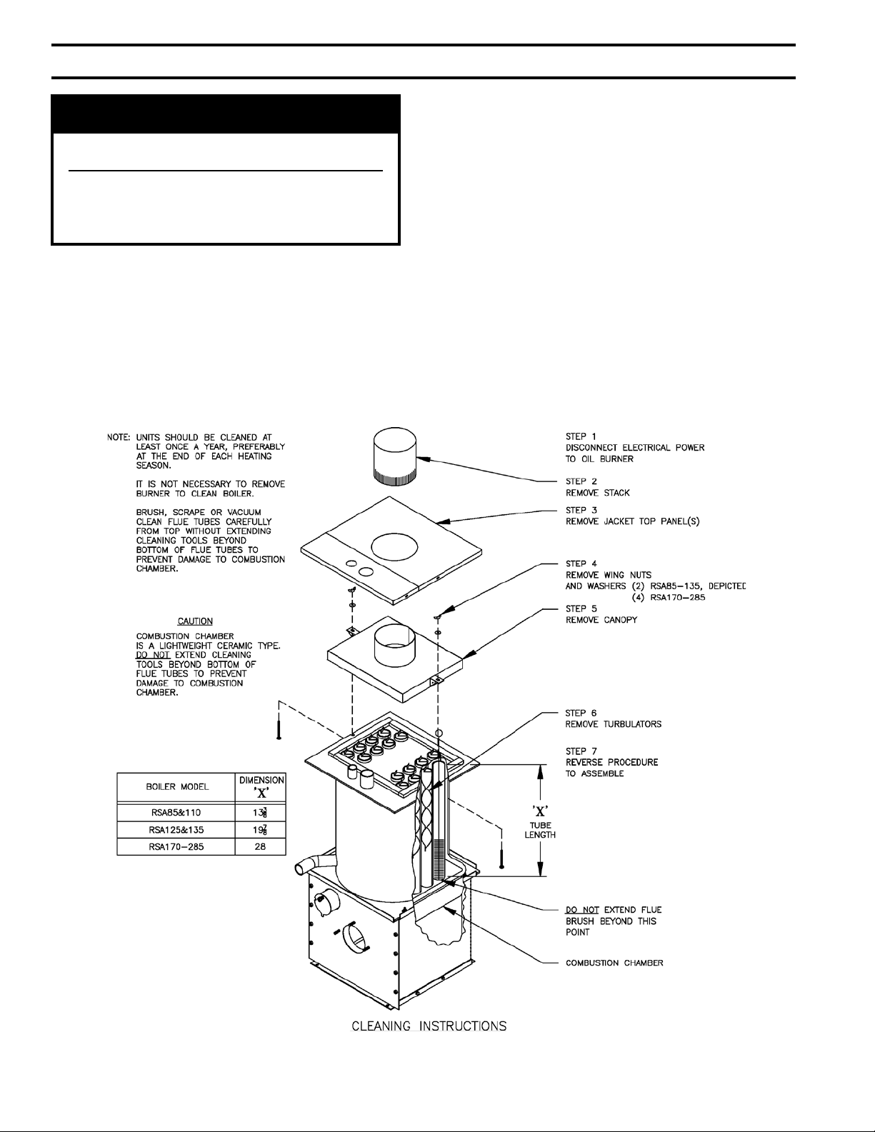
B. Firetubes and Combustion Chamber. (See Figure 27)
1. CLEAN THE FIRETUBES
a. Disconnect electric to burner and remove stack.
b. For access to the retubes, pull top jacket panel
off. Loosen wing nuts, that hold canopy down.
Without taking wing nuts off carriage bolts,
disengage bolts from slots on tubesheet. Pull
canopy off.
c. Remove turbulators.
d. Using a retube brush clean retubes. DO
NOT extend brush past the end of the bottom
tubesheet.
e. Assemble the boiler in reverse order.
Units should be cleaned at least once a year, preferably
at the end of each heating season.
It is not necessary to remove burner to clean boiler.
Brush, scrape, or vacuum from top.
38
Figure 27: Cleaning of RSA Boiler
Page 39

Important Product Safety Information
Refractory Ceramic Fiber Product
Warning:
The Repair Parts list designates parts that contain refractory ceramic fibers
(RCF). RCF has been classified as a possible human carcinogen. When
exposed to temperatures about 1805°F, such as during direct flame contact,
RCF changes into crystalline silica, a known carcinogen. When disturbed as a
result of servicing or repair, these substances become airborne and, if inhaled,
may be hazardous to your health.
AVOID Breathing Fiber Particulates and Dust
Precautionary Measures:
Do not remove or replace RCF parts or attempt any service or repair work
involving RCF without wearing the following protective gear:
1. A National Institute for Occupational Safety and Health (NIOSH)
approved respirator
2. Long sleeved, loose fitting clothing
3. Gloves
4. Eye Protection
• Take steps to assure adequate ventilation.
• Wash all exposed body areas gently with soap and water after contact.
• Wash work clothes separately from other laundry and rinse washing
machine after use to avoid contaminating other clothes.
• Discard used RCF components by sealing in an airtight plastic bag. RCF
and crystalline silica are not classified as hazardous wastes in the United
States and Canada.
First Aid Procedures
:
• If contact with eyes: Flush with water for at least 15 minutes. Seek
immediate medical attention if irritation persists.
• If contact with skin: Wash affected area gently with soap and water.
Seek immediate medical attention if irritation persists.
• If breathing difficulty develops: Leave the area and move to a location
with clean fresh air. Seek immediate medical attention if breathing
difficulties persist.
• Ingestion: Do not induce vomiting. Drink plenty of water. Seek
immediate medical attention.
39
Page 40

IX. Repair Parts
All RSA™ Repair Parts may be obtained through your local Burnham Wholesale distributor.
Should you require assistance in locating a Burnham distributor in your area, or have questions regarding the availability of Burnham products or repair parts, please contact Burnham
Customer Service at (717) 481-8400 or Fax (717) 481-8408.
For Carlin oil burner replacement parts, contact your wholesaler or Carlin:
CCT, Carlin Combustion Technology, Inc.
70 Maple Street
East Longmeadow, MA 01028
Tel: (413) 525-7700
Fax: (413) 525-8306
40
Page 41

ITEM DESCRIPTION PART NUMBER
1 Jacket Rear Top Panel 604350864
2 Jacket Front Top Panel 604350863
3
4 Temperature / Pressure Gauge 100282-03
5
6
7 Burner Primary Control, R7184B 80160847
Jacket Wrap-A-Round Panel, RSA85/110 60435087
Jacket Wrap-A-Round Panel, RSA125/135 60435088
Honeywell L7248C1014 Hi-Limit Control 100059-01
Honeywell L7224C1004 Limit Control 100862-01
Observation Port Cover 7026001
Observation Cover Sprint V1 8026015
Flat Washer, SAE, 5/16” 80860647
Hex Nut, 5/16” -18, Heavy 80860402
Fogire 28: Assembled Boiler
41
Page 42

NOTE: When ordering parts always give the serial number and model number shown on the boiler. Also provide the name of
the part(s) shown below:
42
Figure 29: RSA85-135 Bare Boiler Repair Parts
Page 43

ITEM QTY. DESCRIPTION PART NUMBER
1 2 Wing Nut, 1/4 -20 80860910
2 10 Washer, Flat 1/4 (SAE) 80860633
3 1 Canopy Assembly 6113509
4 2 1/2” Thick x 1” x 12-3/8” Cerafelt Strip 9206005
5 2 1/2” Thick x 1” x 12-3/8” Cerafelt Strip 9206005
6 2 Carriage Bolt, 1/4 -20 x 3” Lg. 80860119
7
8 1 Heat Exchanger Assembly
9 10 SA307B 3/8 -16 x 1-1/4” Bolt 80861360
10 1 Tankless Heater Gasket 8206036
11 1 Tapped Heater Cover Plate 7036030
12 1
13 10 Washer, Flat (USS), 3/8” 80860645
14 10 Hex Nut, 3/8 -16, Steel, Plain 80860400
15 2 1/2” Thick x 2” x 13-3/4” Cerafelt Strip 9206003
16 2 1/2” Thick x 2” x 18-1/2” Cerafelt Strip 9206003
17 1 Combustion Chamber 8203006
18 1 Cerablanket 8203512
19 1 Base Assembly 6183508
20 4 Machine Screw, Hex Head, 1/4 -20 x 1-1/4” 80860810
21 4 Hex Nut, 1/4 -20 (Heavy Hex) 80860407
‘A’
Turbulator 7116037
‘B’
Tankless Heater Coil, (Standard S350) (Includes Item 10) 6033509
Tankless Heater Coil, (Optional S375) (Includes Item 10) 6033510
BOILER MODEL
RSA85 12 603350112
RSA110 16 603350116
RSA125 12 603350212
RSA135 16 603350216
‘A’ ‘B’
43
Page 44

NOTE: When ordering parts always give the serial number and model number shown on the boiler. Also provide the name of
the part(s) shown below:
44
Figure 30: RSA170-285 Boiler Repair Parts
Page 45

ITEM DESCRIPTION PART NUMBER
1 Jacket Top Panel Assembly 60435022
2 Canopy Assembly 6113510
3 1/2” Thick x 1” x 23” Cerafelt Strip 9206005
4 1/2” Thick x 1” x 17” Cerafelt Strip 9206005
5
6 Tankless Heater Gasket 8036025
7
8 Blank Heater Cover Plate 7033501
9 Heat Exchanger Assembly
10 1/2” Thick x 2” x 25” Cerafelt Strip 9206003
11 1/2” Thick x 2” x 21” Cerafelt Strip 9206003
12 Combustion Chamber 8203003
13 Block Insulation Assembly Supplied with Item #12
14 Jacket Left Side Panel Assembly 60435061
15 Jacket Upper Front Panel Assembly 60435033
16 Jacket Lower Front Panel Assembly 60435042
17 Base Assembly with Insulation 6186031
18 Jacket Rear Panel Assembly 60435071
19 Jacket Right Side Panel Assembly 60435051
21 Hex Nut, 1/4 -20 (Heavy Hex) 80860407
Turbulator, See ‘A’ for Quantity
#7524 Tankless Heater Assembly (Includes Item 6) 6033507
#7530 Tankless Heater Assembly (Includes Item 6) 6033508
6113504
‘B’
BOILER MODEL
RSA85 12 603350112
RSA110 16 603350116
RSA125 12 603350212
RSA135 16 603350216
‘A’ ‘B’
45
Page 46

BECKETT BURNER PARTS LIST FOR RSA SERIES STEEL BOILERS
FOR REPLACEMENT OIL BURNER PARTS, CONTACT YOUR WHOLESALER OR THE BURNER
MANUFACTURER:
R. W. BECKETT CORP.
38251 CENTER RIDGE RD.
P. O. BOX 1289
ELYRIA, OHIO 44036
1-800-645-2876
NOTE: When ordering parts always give the serial and model numbers shown on the boiler and burner. Also, provide the
name of the part(s) and part(s) number as listed below.
Boiler Model RSA85 RSA110 RSA125 RSA135
Burner Model AFG AFG AFG AFG
Air Tube Combination AF60BN AF60XN AF60J2 AF60JZSS
Spec. No. BCB6211 BCB6212 BCB6213 BCB6214
Air Band 3492BKA 3492BKA 3492BKA 3492BKA
Air Band Nut 4150 4150 4150 4150
Air Band Screw 4198 4198 4198 4198
Air Shutter 3709BK 3709BK 3709BK 3709BK
Air Shutter Screw 4198 4198 4198 4198
Blower 2999 2999 2999 2999
Bulkhead Fitting 3488 3488 3488 3488
Bulkhead Fitting Locknut 3666 3666 3666 3666
Connector Tube Assembly 5636 5636 5636 5636
Coupling 2454 2454 2454 2454
Electrode Clamp 149 149 149 149
Electrode Clamp Screw 4219 4219 4219 4219
Electrode Insulator Assembly EA21502 EA21502 EA21502 EA21502
Spider Spacer Assembly 5653 5653 5653 5653
Escutcheon Plate 3493 3493 3493 3493
Flange and Air Tube Assembly 3146812 3146812 3146812 3146812
Gasket 31498 31498 31498 31498
Head 360003 360003 360006 360006
Head Screws 4221 4221 4221 4221
Hole Plug 2139 2139 2139 2139
Housing Assembly w/Inlet Bell 5624 5624 5624 5624
Motor 2456 2456 2456 2456
Nozzle Adapter 213 213 213 213
Nozzle Line Electrode Assembly NC6058 NC6058 NC6058 NC6048
Pump (Includes Valve) 21844 21844 21844 21844
Static Plate 31646 3383P 31646 31646
Ignitor 51771U 51771U 51771U 51771U
Ignitor Hinge Screw 4217 4217 4217 4217
Ignitor Holding Screw 4198 4198 4198 4198
Ignitor Gasket Kit 51304 51304 51304 51304
Wire Guard 3345 3345 3345 3345
Bafe 3708 N/A N/A N/A
46
Page 47

Ordering Information for Quality Replacement Parts
Figure 31: BECKETT AFG MODEL BURNER
47
Page 48

BECKETT BURNER PARTS LIST FOR RSA SERIES STEEL BOILERS
FOR REPLACEMENT OIL BURNER PARTS, CONTACT YOUR WHOLESALER OR THE BURNER
MANUFACTURER:
R. W. BECKETT CORP.
38251 CENTER RIDGE RD.
P. O. BOX 1289
ELYRIA, OHIO 44036
1-800-645-2876
Boiler Model RSA170 RSA195 RSA240/285
Burner Model AF AF SF
Air Tube Combination AF60XO AF60XP SF60FY
Spec. No. BCB114 BCB116 BCB211
1) Air Band 3492 3492 3492
Air Band Nut 4150 4150 460
Air Band Screw 4198 4198 4219
2) Air Shutter 3494 3494 3215
Air Shutter Screw 4198 4198 493
6) Blower 2459 2459 2288
7) Bulkhead Fitting 3488 3488 3488
8) Bulkhead Fitting Locknut 3666 3666 3666
9) Connector Tube Assembly 5636 5636 5636
10) Coupling 2454 2454 2433
11) Electrode Clamp 149 149 149
Electrode Clamp Screw 4219 4219 4219
12) Electrode Insulator Assembly EA21502 EA21502 EA21502
15) Spider Spacer Assembly 5653 5653 5653
16) Escutcheon Plate 3493 3493 3493
18) Flange and Air Tube Assembly 58115 58115 58115
Gasket 3616 3616 3616
19) Head 360012 360022 5434
Head Screws 4221 4221 4221
Hole Plug 2139 2139 2139
20) Housing Assembly w/Inlet Bell 5624 5624 53485
21) Motor 2456 2456 2364
22) Nozzle Adapter 213 213 213
23) Nozzle Line Electrode Assembly NC6048 NC6058 NC6048
25) Pump (Includes Valve) 21844 21844 21844
27) Static Plate 3383 3383 3383
28) Ignitor 51824U 51824U 51824U
29) Ignitor Hinge Screw 4217 4217 4217
30) Ignitor Holding Screw 4198 4198 4198
31) Ignitor Gasket Kit 51304 51304 51304
21) Wire Guard 3345 3345 3345
48
Page 49
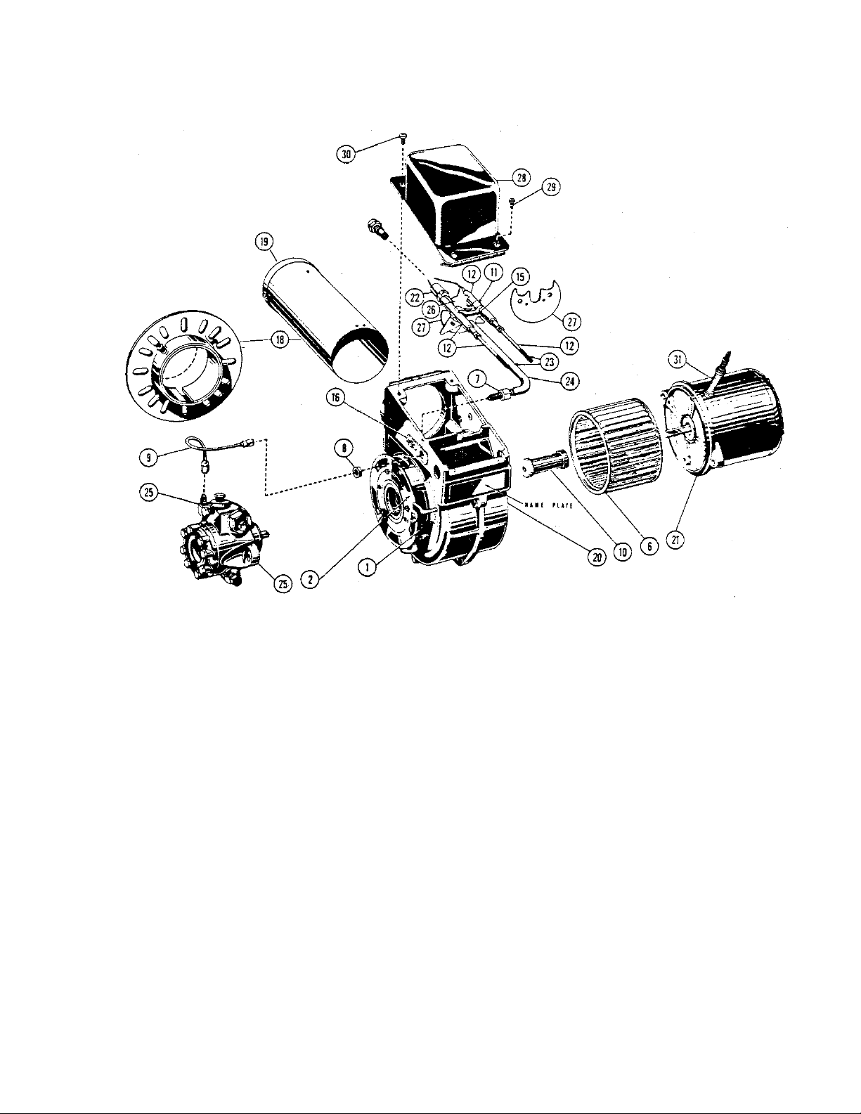
Figure 32: BECKETT AF and SF MODEL BURNERS
49
Page 50

X. Low Water Cut Off (LWCO)
WARNING
DO NOT ATTEMPT to cut factory wires to install an aftermarket Low Water Cut Off (LWCO).
Only use connections specically identied for Low Water Cut Off.
In all cases, follow the Low Water Cut Off (LWCO) manufacturer's instructions.
When
A low water cutoff is required to protect a hot water
boiler when any connected heat distributor (radiation)
is installed below the top of the hot water boiler (i.e.
baseboard on the same oor level as the boiler). In
addition, some jurisdictions require the use of a LWCO
with a hot water boiler.
Where
The universal location for a LWCO on both gas and
oil hot water boilers is above the boiler, in either the
supply or return piping. The minimum safe water level
of a water boiler is at the uppermost top of the boiler;
that is, it must be full of water to operate safely.
What Kind
Typically, in residential applications, a probe type
LWCO is used instead of a oat type, due to their
relative costs and the simplicity of piping for a probe
LWCO.
How to Pipe
A “tee” is commonly used to connect the probe LWCO
to the supply or return piping, as shown below.
draining the heating system. Many probe LWCO
manufacturers recommend an annual inspection of the
probe.
How to Wire
LWCO’s are available in either 120 VAC or 24 VAC
congurations. The 120 VAC conguration can be
universally applied to both gas and oil boilers by wiring
it in the line voltage service to the boiler (after the
service switch, if so equipped).
The presence of water in a properly installed LWCO
will cause the normally open contact of the LWCO to
close, thus providing continuity of the 120 VAC service
to the boiler.
It is recommended to supply power to the probe LWCO
with the same line voltage boiler service as shown
below.
LWCO Location
Select the appropriate size tee using the LWCO
manufacturer’s instructions. Often, the branch
connection must have a minimum diameter to
prevent bridging between the probe and the tee. Also,
the run of the tee must have a minimum diameter to
prevent the end of the probe from touching or being
located too close to the inside wall of the run of the tee.
Ideally, manual shutoff valves should be located
above the LWCO and the boiler to allow for servicing.
This will allow probe removal for inspection without
50
Wiring of Typical LWCO
A 24 VAC LWCO is used primarily for gas red
boilers where a 24 volt control circuit exists within the
boiler. However, a 24 VAC LWCO can only be used
if the boiler manufacturer has provided piping and
wiring connections and instructions to allow for this
application.
How to Test
Shut off fuel supply. Lower water level until water
level is BELOW the LWCO. Generate a boiler demand
by turning up thermostat. Boiler should not attempt to
operate. Increase the water level by lling the system.
The boiler should attempt to operate once the water
level is above the LWCO.
Page 51

SERVICE RECORD
DATE SERVICE PERFORMED
51
Page 52

LLiim
miitteedd
W
Waarrrraannttyy
FFoorrRReessiiddeennttiiaallGGrraaddeeWWaatteerraannddSStteeaammBBooiilleerrs
s
Using Cast Iron, Carbon Steel, Cast Aluminum,
or Stainless Steel Heat Exchangers
aannddPPaarrttss//AAcccceessssoorriiees
s
Subject to the terms and conditions set forth below, U.S. Boiler Company, Inc.
Lancaster, Pennsylvania hereby extends the following limited warranties to the original
owner of a residential grade water or steam boiler or U.S. Boiler Company, Inc. supplied
parts and/or accessories manufactured and shipped on or after July 1, 2008:
ONE YEAR LIMITED WARRANTY ON RESIDENTIAL GRADE BOILERS
AND PARTS / ACCESSORIES SUPPLIED BY U.S. BOILER COMPANY, INC.
U.S. Boiler Company, Inc. warrants to the original owner that its residential grade
water and steam boilers and parts/accessories comply at the time of manufacture with
recognized hydronic industry standards and requirements then in effect and will be
free of defects in material and workmanship under normal usage for a period of one
year from the date of original installation. If any part of a residential grade boiler or
any part or accessory provided by U.S. Boiler Company, Inc. is found to be defective
in material or workmanship during this one year period, U.S. Boiler Company, Inc.
will, at its option, repair or replace the defective part.
HEAT EXCHANGER WARRANTIES
U.S. Boiler Company, Inc. warrants to the original owner that the heat exchanger of its
residential grade boilers will remain free from defects in material and workmanship
under normal usage for time period specified in the chart below of the original owner at
the original place of installation. If a claim is made under this warranty during the “No
Charge” period from the date of original installation, U.S. Boiler Company, Inc. will, at its
option, repair or replace the heat exchanger. If a claim is made under this warranty after
the expiration of the “No Charge” period from the date of original installation, U.S. Boiler
Company, Inc. will, at its option and upon payment of the pro-rated service charge set
forth below, repair or replace the heat exchanger. The service charge applicable to a
heat exchanger warranty claim is based upon the number of years the heat exchanger
has been in service and will be determined as a percentage of the retail price of the heat
exchanger model involved at the time the warranty claim is made as follows:
NOTE: If the heat exchanger involved is no longer available due to product obsolescence
or redesign, the value used to establish the retail price will be the published price as
shown in the Burnham
Repair Parts Pricing where the heat exchanger last
appeared or the current retail price of the then nearest equivalent heat exchanger.
*MegaSteam Waterside Corrosion Warranty: U.S. Boiler Company, Inc. warrants the
cast iron sections of the MegaSteam boiler to resist Temperature Induced Chloride
Activated Graphitic Corrosion for a period of five years from the date of original
installation. In the event that any cast iron section of a Mega Steam boiler fails due to
this corrosion mechanism during this period, U.S. Boiler Company, Inc. will repair or
replace, at its option, the cast iron section assembly.
LIFETIME NIPPLE LEAKAGE WARRANTY
U.S. Boiler Company, Inc. warrants the cast iron and steel nipples that join the cast iron
boiler sections to be free of defects in material and workmanship for the lifetime of the
original owner at the original place of installation. In the event that such nipples are
found to be defective in material and workmanship during this period, U.S. Boiler
Company, Inc. will repair or replace at its option, the cast iron section assembly.
ADDITIONAL TERMS AND CONDITIONS
1. Applicability: The limited warranties set forth above are extended only to the
original owner at the original place of installation within the United States and
Canada. These warranties are applicable only to boilers, parts, or accessories
designated as residential grade by U.S. Boiler Company, Inc. and installed in a
single or two-family residence and do not apply to commercial grade products.
2. Components Manufactured by Others: Upon expiration of the one year limited
warranty on residential grade boilers, all boiler components manufactured by
others but furnished by U.S. Boiler Company, Inc. (such as oil burner, circulator
and controls) will be subject only to the manufacturer’s warranty, if any.
3. Proper Installation: The warranties extended by U.S. Boiler Company, Inc.
are conditioned upon the installation of the residential grade boiler, parts, and
accessories in strict compliance with U.S. Boiler Co., Inc. installation
instructions. U.S. Boiler Company, Inc. specifically disclaims liability of any
kind caused by or relating to improper installation.
4. Proper Use and Maintenance: The warranties extended by U.S. Boiler Company,
Inc. conditioned upon the use of the residential grade boiler, parts, and
accessories for its intended purposes and its maintenance accordance with U. S.
Boiler Company, Inc. recommendations and hydronics industry standards. For
proper installation, use, and maintenance, see all applicable sections of the
Installation and Operating, and Service Instructions Manual furnished with the unit.
5. This warranty does not cover the following:
a. Expenses for removal or reinstallation. The homeowner will be responsible
for the cost of removing and reinstalling the alleged defective part or its
replacement and all labor and material connected therewith, and
transportation to and from U.S. Boiler Company, Inc.
b. Components that are part of the heating system but were not furnished by
U.S. Boiler Company, Inc. as part of the residential boiler.
c. Improper burner adjustment, control settings, care or maintenance.
d. This warranty cannot be considered as a guarantee of workmanship of an
installer connected with the installation of the U.S. Boiler Company, Inc.
boiler, or as imposing on U.S. Boiler Company, Inc. liability of any nature for
unsatisfactory performance as a result of faulty workmanship in the
installation, which liability is expressly disclaimed.
e. Boilers, parts, or accessories installed outside the 48 contiguous United
States, the State of Alaska and Canada.
f. Damage to the boiler and/or property due to installation or operation of the
boiler that is not in accordance with the boiler installation and operating
instruction manual.
g. Any damage or failure of the boiler resulting from hard water or scale
buildup in the heat exchanger.
h. Any damage caused by improper fuels, fuel additives or contaminated
combustion air that may cause fireside corrosion and/or clogging of the
burner or heat exchanger.
i. Any damage resulting from combustion air contaminated with particulate
which cause clogging of the burner or combustion chamber including but
not limited to sheetrock or plasterboard particles, dirt, and dust particulate.
j. Any damage, defects or malfunctions resulting from improper operation,
maintenance, misuse, abuse, accident, negligence including but not limited to
operation with insufficient water flow, improper water level, improper water
chemistry, or damage from freezing.
k. Any damage caused by water side clogging due to dirty systems or
corrosion products from the system.
l. Any damage resulting from natural disaster.
m. Damage or malfunction due to the lack of required maintenance outlined in
the Installation and Operating Manual furnished with the unit.
6. Exclusive Remedy: U.S. Boiler Company, Inc. obligation for any breach of
these warranties is limited to the repair or replacement of its parts in
accordance with the terms and conditions of these warranties.
7. Limitation of Damages: Under no circumstances shall U.S. Boiler Company, Inc.
be liable for incidental, indirect, special or consequential damages of any kind
whatsoever under these warranties, including, but not limited to, injury or damage
to persons or property and damages for loss of use, inconvenience or loss of time.
U.S. Boiler Company, Inc. liability under these warranties shall under no
circumstances exceed the purchase price paid by the owner for the residential
grade boiler involved. Some states do not allow the exclusion or limitation of
incidental or consequential damages, so the above limitation or exclusion may not
apply to you.
8. Limitation of Warranties: These warranties set forth the entire obligation of U.S.
Boiler Company, Inc. with respect to any defect in a residential grade boiler, parts,
or accessories and U.S. Boiler Company, Inc. shall have no express obligations,
responsibilities or liabilities of any kind whatsoever other than those set forth
herein. These warranties are given in lieu of all other express warranties.
ALL APPLICABLE IMPLIED WARRANTIES, IF ANY, INCLUDING ANY
WARRANTY OF MERCHANTABILITY OR FITNESS FOR A PARTICULAR
PURPOSE ARE EXPRESSLY LIMITED IN DURATION TO A PERIOD OF ONE
YEAR EXCEPT THAT IMPLIED WARRANTIES, IF ANY, APPLICABLE TO
THE HEAT EXCHANGER IN A RESIDENTIAL GRADE BOILER SHALL
EXTEND TO THE ORIGINAL OWNER FOR THE TIME SPECIFIED IN THE
HEAT EXCHANGER SECTION SHOWN ABOVE AT THE ORIGINAL PLACE
OF INSTALLATION. SOME STATES DO NOT ALLOW LIMITATION ON HOW
LONG AN IMPLIED WARRANTY LASTS, SO THE ABOVE LIMITATION MAY
NOT APPLY TO YOU.
PROCEDURE FOR OBTAINING WARRANTY SERVICE
In order to assure prompt warranty service, the owner is requested to complete
and mail the Warranty Card provided with the product or register product online
at www.burnham.com within ten days after the installation of the boiler, although
failure to comply with this request will not void the owner’s rights under these
warranties. Upon discovery of a condition believed to be related to a defect in
material or workmanship covered by these warranties, the owner should notify
the installer, who will in turn notify the distributor. If this action is not possible or
does not produce a prompt response, the owner should write to U.S. Boiler
Company, Inc.,
C/O Burnham, P.O. Box 3079, Lancaster, PA 17604, giving
full particulars in support of the claim. The owner is required to make available
for inspection by U.S. Boiler Company, Inc. or its representative the parts
claimed to be defective and, if requested by U.S. Boiler Company, Inc. to ship
these parts prepaid to U.S. Boiler Company, Inc. at the above address for
inspection or repair. In addition, the owner agrees to make all reasonable efforts
to settle any disagreement arising in connection with a claim before resorting to
legal remedies in the courts.
THIS WARRANTY GIVES YOU SPECIFIC LEGAL RIGHTS AND YOU MAY
ALSO HAVE OTHER RIGHTS WHICH VARY FROM STATE TO STATE.
Years in Service 1-5 6 7 8 9 10 11 12 13 14 15 16 17 18 19 20 21 22 23 24 25+
Cast Iron Water 5 15 20 25 30 40 45 50 55 60 65 70 75
Cast Iron Steam*
Carbon Steel 5 15 20 25 30 40 45 50 55 60 65 70 75
Cast Aluminum 30 40 50 60 70
Stainless Steel 30 40 50 60 70
Service Charge as a % of Retail Price
No Charge 10
No Charge 10
No Charge 100
No Charge 100
No Charge 100
52
 Loading...