

Page 1
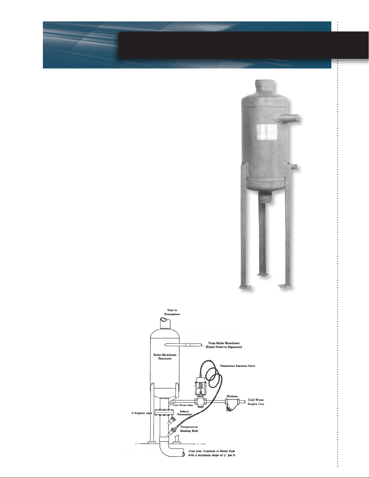
Bottom Blowdown Separator
• Eliminate precipitated solids from the bottom of the boiler.
• Cools blowdown to 140°F or below before dumping to
drain by introducing cooling water via an aftercooler.
• ASME Section VIII “UE” stamped separator
(“U” stamp available as option).
• Sized to accommodate ow based on boiler blowdown
line size and boiler operating pressure.
• Model Range:
14" diameter x 22" through 56" in height
for standard boilers.
(10" diameter x 14" high option available
for boilers under 1000 #/hour).
• Modular conguration to meet customer requirements
includes: separator, legs (or wall bracket), aftercooler,
temperature regulating valve and thermometer.
• Can be custom congured to meet customer requirements.
• Stainless steel striking plate standard and internal steel
restrictor plates standard.
• Multiple separators with manifold for high pressure
applications available.
Page 2
Bottom Blowdown Separator
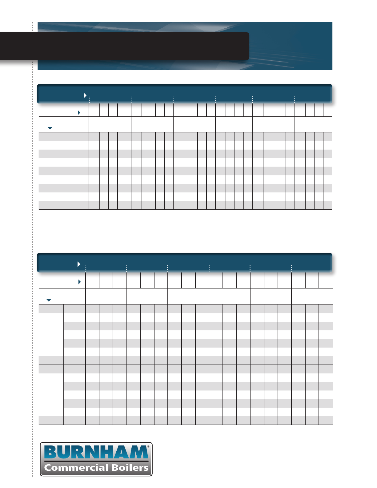
Chart A—Boiler Blowdown Separators
BLOWDOWN VALVE
SIZE SEPARATOR
DIMENSIONS H I D V H I D V H I D V H I D V H I D V H I D V
BOILER OPERATING
PRESSURE
0 – 15 14 1 2 2-1/2 20 1-1/4 3 4 20 1-1/2 3 4 20 2 4 5 34 2-1/2 5 6 34 3 6 5
16 – 50 20 1 2 2-1/2 20 1-1/4 3 4 34 1-1/2 3 4 34 2 4 5 34 2-1/2 5 6 34 3 6 5
51 – 100 20 1 3 2-1/2 34 1-1/4 4 4 34 1-1/2 4 4 34 2 5 5 34 2-1/2 6 6 34 3 8 6
101 – 125 34 1 3 3 34 1-1/4 4 4 34 1-1/2 4 4 34 2 5 5 56 2-1/2 6 6 – – – –
126 – 150 34 1 3 3 34 1-1/4 4 4 34 1-1/2 4 5 56 2 5 6 56 2-1/2 6 6 – – – –
151 – 175 34 1 3 4 34 1-1/4 4 4 34 1-1/2 4 5 56 2 5 6 56 2-1/2 6 8 – – – –
176 – 200 34 1 3 4 34 1-1/4 4 5 56 1-1/2 5 5 56 2 6 6 56 2-1/2 6 8 – – – –
201 – 225 34 1 4 4 56 1-1/4 4 5 56 1-1/2 5 5 56 2 6 6 56 2-1/2 8 8 – – – –
** 226 – 300 56 1 4 4 56 1-1/4 4 5 56 1-1/2 5 6 56 2 6 6 56 2-1/2 8 8 – – – –
* Miniature Boilers: 1/2" – 1" Blowdown Valve up to 1000 #/hour. Blowdown use 14" high, 1" Inlet, 2" Drain, 2-1/2" Vent.
** 251 – 300 PSIG required.
U Symbol Construction and Stamping. See price sheet for adder.
* 1"
11/4"
11/2"
2"
21/2"
3"
Chart B—Cooling Water Line & Valve Size
SEPARATOR
INLET SIZE
COOLING WATER
PRESSURE PSI 40# 60# 80# 40# 60# 80# 40# 60# 80# 40# 60# 80# 40# 60# 80# 40# 60# 80#
BOILER OPERATING
PRESSURE
0 – 50 1/2 1/2 1/2 1 1 3/4 1-1/4 1 1 1-1/4 1-1/4 1-1/4 1-1/2 1-1/2 1-1/4 2 2 2
Use for
50 – 70°F
Cooling
Water
Temperature
Use for
71 – 80°F
Cooling
Water
Temperature
51 – 100 1 3/4 3/4 1 1 1 1-1/4 1-1/4 1 1-1/2 1-1/4 1-1/4 2 2 2 2-1/2 2-1/2 2
101 – 125 1 3/4 3/4 1-1/4 1 1 1-1/4 1-1/4 1-1/4 2 1-1/2 1-1/4 2 2 2 2-1/2 2-1/2 2-1/2
126 – 175 1 1 1 1-1/4 1-1/4 1 1-1/4 1-1/4 1-1/4 2 2 1-1/2 2-1/2 2 2 2-1/2 2-1/2 2-1/2
176 – 225 1 1 1 1-1/4 1-1/4 1-1/4 1-1/2 1-1/4 1-1/4 2 2 2 2-1/2 2 2 3 2-1/2 2-1/2
226 – 250 1-1/4 1-1/4 1 1-1/4 1-1/4 1-1/4 1-1/2 1-1/4 1-1/4 2 2 2 2-1/2 2 2 3 2-1/2 2-1/2
251 – 300 1-1/4 1-1/4 1 1-1/4 1-1/4 1-1/4 1-1/2 1-1/4 1-1/4 2 2 2 2-1/2 2-1/2 2 3 3 2-1/2
0 – 50 3/4 1/2 1/2 1 1 1 1 1 1 1-1/4 1-1/4 1-1/4 2 1-1/2 1-1/2 2-1/2 2 2
51 – 100 1 3/4 3/4 1-1/4 1 1 1-1/4 1-1/4 1-1/4 2 1-1/2 1-1/4 2 2 2 2-1/2 2-1/2 2
101 – 125 1 1 3/4 1-1/4 1-1/4 1 1-1/4 1-1/4 1-1/4 2 2 1-1/2 2-1/2 2 2 2-1/2 2-1/2 2-1/2
126 – 175 1 1 1 1-1/4 1-1/4 1-1/4 1-1/4 1-1/4 1-1/4 2 2 2 2-1/2 2 2 3 2-1/2 2-1/2
176 – 225 1 1 1 1-1/4 1-1/4 1-1/4 1-1/4 1-1/4 1-1/4 2 2 2 2-1/2 2-1/2 2 4 3 2-1/2
226 – 250 1-1/4 1-1/4 1 1-1/4 1-1/4 1-1/4 1-1/4 1-1/4 1-1/4 2-1/2 2 2 2-1/2 2-1/2 2 4 3 2-1/2
251 – 300 1-1/4 1-1/4 1-1/4 1-1/2 1-1/4 1 1-1/2 1-1/2 1-1/2 2-1/2 2 2 2-1/2 2-1/2 2-1/2 4 3 2-1/2
1"
11/4"
11/2"
2"
21/2"
3"
©2012 Burnham Commercial
P.O. Box 3939 • Lancaster, PA 17604
Phone: 888.791.3790 • Fax: 717.293.5803
www.burnhamcommercial.com
Form No. PL81465601007-12/12-1Mc
Printed in the U.S.A.
 Loading...