

Burkert 8026, SE36, 8036 Quick Start Manual
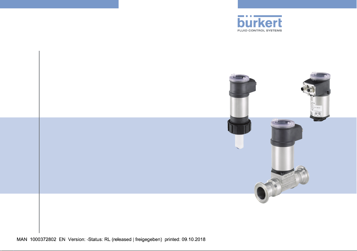
Type 8026 - 8036 - SE36
Flowmeter and Flow transmitter
Durchfluss-Messgerät und Durchfluss-Transmitter
Débitmètre et transmetteur de débit
Quickstart
English Deutsch Français
We reserve the right to make technical changes without notice.
Technische Änderungen vorbehalten.
Sous réserve de modifications techniques.
© Bürkert SAS, 2009 - 2018
Operating Instructions 1809/03_EU-ML 00567366 / Original_FR
Type 8026 - 8036 - SE36
Contents
1 ABOUT THE QUICKSTART .....................................................................4
1.1 Definition of the word "device" ................................................... 4
1.2 Validity of the quickstart ............................................................... 4
1.3 Symbols used ................................................................................. 4
2 INTENDED USE .............................................................................................5
3 BASIC SAFETY INFORMATION ............................................................6
4 GENERAL INFORMATION ........................................................................7
4.1 Manufacturer's address and international contacts ...............7
4.2 Warranty conditions ...................................................................... 7
4.3 Information on the Internet ..........................................................7
5 DESCRIPTION OF THE RATING PLATE ............................................8
6 TECHNICAL DATA ........................................................................................9
6.1 Conditions of use .......................................................................... 9
6.2 Conformity to standards and directives ................................... 9
6.3 Dimensions of devices ................................................................. 9
6.4 Materials ........................................................................................10
6.5 Fluid data .......................................................................................12
6.6 Electrical data ...............................................................................14
7 INSTALLATION AND WIRING ..............................................................16
7.1 Safety instructions .......................................................................16
7.2 Installation of a 8026 on a pipe ...............................................16
7.3 Installation of a 8036 on a pipe ...............................................18
7.4 Installation of a flow transmitter SE36 with sensor-fitting
S070 or S077 in a pipe .............................................................19
7.5 Wiring .............................................................................................21
8 ADJUSTMENT AND COMMISSIONING .........................................27
8.1 Safety instructions .......................................................................27
8.2 Knowing the Operating levels ..................................................27
8.3 Using the navigation button ......................................................28
8.4 Using the dynamic functions .....................................................30
8.5 Knowing the display ....................................................................30
8.6 Knowing the process level ........................................................32
8.7 Knowing the configuration level ...............................................34
9 MAINTENANCE AND TROUBLESHOOTING ............................... 41
9.1 Safety instructions .......................................................................41
9.2 If you encounter problems .........................................................41
10 PACKAGING, TRANSPORT .................................................................. 41
11 STORAGE ......................................................................................................41
12 DISPOSAL OF THE DEVICE ................................................................ 42
English
3
Type 8026 - 8036 - SE36
About the Quickstart
1 ABOUT THE QUICKSTART
This quickstart describes the entire life cycle of the device. Please
keep this quickstart in a safe place, accessible to all users and any
new owners.
This quickstart contains important safety information.
Failure to comply with these instructions can lead to hazardous
situations. Pay attention in particular to the chapters „Basic safety
information“ and „Intended use“.
▶ Irrespective the version of the device, this quickstart must be
read and understood.
The quickstart explains how to install, adjust, and start-up the device.
A detailed description of the device can be found in the related
Operating Instructions available on the internet at: www.burkert.com
1.1 Definition of the word "device"
The word "device" used within this quickstart refers to:
• the Type 8026 flowmeter,
• the Type 8036 flowmeter,
• or the Type SE36 flow transmitter.
1.2 Validity of the quickstart
This quickstart is valid for the following devices:
• Type 8026 flowmeter, from the version V2,
• Type 8036 flowmeter, from the version V2,
• Type SE36 flow transmitter, from the version V2.
These informations are available on the rating plate, see chap. 5.
1.3 Symbols used
Danger
Warns against an imminent danger.
▶ Failure to observe this warning can result in death or in serious
injury.
Warning
Warns against a potentially dangerous situation.
▶ Failure to observe this warning can result in serious injury or
even death.
Caution
Warns against a possible risk.
▶ Failure to observe this warning can result in substantial or minor
injuries.
notiCe
Warns against material damage.
4
English
Type 8026 - 8036 - SE36
Intended use
Indicates additional information, advice or important
recommendations.
Refers to information contained in this quickstart or in other
documents.
▶ Indicates an instruction to be carried out to avoid a danger, a
warning or a possible risk.
→ Indicates a procedure to be carried out.
Indicates the result of a specific instruction.
2 INTENDED USE
Use of the device that does not comply with the instructions
could present risks to people, nearby installations and the
environment.
Type 8026 flowmeter, Type 8036 flowmeter and Type SE36
flow transmitter associated with a sensor-fitting are intended to
measure the flow rate of liquids.
▶ Use this device in compliance with the characteristics and
commissioning and use conditions specified in the contractual
documents and in the Operating Instructions.
▶ Never use this device for security applications.
▶ Protect this device against electromagnetic interference, ultra-
violet rays and, when installed outdoors, the effects of climatic
conditions.
▶ Use this device only if in perfect working order.
▶ Requirements for the safe and proper operation of the device
are proper transport, storage and installation, as well as careful
operation and maintenance.
▶ Only use the device as intended.
English
5
3 BASIC SAFETY INFORMATION
This safety information does not take into account any contingencies
or occurrences that may arise during installation, use and maintenance of the device.
The operating company is responsible for the respect of the local
safety regulations including staff safety.
Danger due to electrical voltage.
▶ If a 12...36 V DC or a 14...36 V DC powered version is installed
either in a wet environment or outdoors, all the electrical voltages must be of max. 35 V DC.
▶ Disconnect the electrical power for all the conductors and iso-
late it before carrying out work on the system.
▶ Observe all applicable accident protection and safety regula-
tions for electrical equipment.
Danger due to high pressure in the installation.
▶ Stop the circulation of fluid, cut off the pressure and drain the
pipe before loosening the process connections.
Danger due to high temperatures of the fluid.
▶ Use safety gloves to handle the device.
▶ Stop the circulation of fluid and drain the pipe before loosening
the process connections.
Danger due to the nature of the fluid.
▶ Respect the prevailing regulations on accident prevention and
safety relating to the use of dangerous fluids.
Type 8026 - 8036 - SE36
Basic safety information
Various dangerous situations
To avoid injury take care:
▶ not to use the device for the measurement of gas flow rates.
▶ not to use the device in explosive atmospheres.
▶ not to use the device in an environment incompatible with the
materials it is made of.
▶ not to use fluid that is incompatible with the materials the device
is made of.
▶ not to make any modifications to the device.
▶ not to subject the device to mechanical loads.
▶ to prevent any unintentional power supply switch-on.
▶ to carry out the installation and maintenance work by qualified
and skilled staff with the appropriate tools.
▶ to guarantee a defined or controlled restarting of the process,
after a power supply interruption.
▶ to observe the general technical rules when installing and using
the device.
6
English
Type 8026 - 8036 - SE36
General information
notiCe
The device may be damaged by the fluid in contact with.
▶ Systematically check the chemical compatibility of the com-
ponent materials of the device and the fluids likely to come
into contact with the materials (for example: alcohols, strong
or concentrated acids, aldehydes, alkaline compounds, esters,
aliphatic compounds, ketones, halogenated aromatics or hydrocarbons, oxidants and chlorinated agents).
notiCe
Elements / Components sensitive to electrostatic discharges
▶ This device contains electronic components that are sensitive
to electrostatic discharges. They may be damaged if they are
touched by an electrostatically charged person or object. In the
worst case scenario, these components are instantly destroyed
or go out of order as soon as they are activated.
▶ To minimise or even avoid any damage due to an electro-
static discharge, take all the precautions described in the
EN 61340-5-1 norm.
▶ Also make sure that you do not touch any of the live electrical
components.
4 GENERAL INFORMATION
4.1 Manufacturer's address and international contacts
To contact the manufacturer of the device, use following address:
Bürkert SAS
Rue du Giessen
BP 21
F-67220 TRIEMBACH-AU-VAL
You may also contact your local Bürkert sales office.
The addresses of our international sales offices are available on the
internet at: www.burkert.com
4.2 Warranty conditions
The condition governing the legal warranty is the conforming use of
the device in observance of the operating conditions specified in the
Operating Instructions.
4.3 Information on the Internet
You can find the Operating Instructions and technical data sheets for
Type 8026, Type 8036 and Type SE36 at: www.burkert.com
English
7
Type 8026 - 8036 - SE36
8026 Flow-Meter V2
1
8
10
11
12
Description of the rating plate
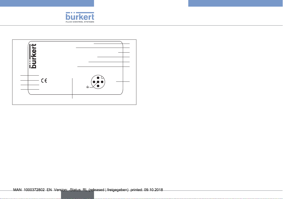
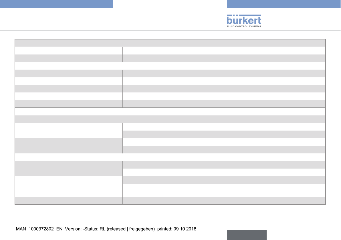
5 DESCRIPTION OF THE RATING PLATE
Supply: 14-36VDC
Output: 1x4-20mA 2xTransistors 500 mA Max
Cell: HALL INSERTION SHORT
Process: Temp -15/100°C
PN 10 Bar
Made in France
IP65-IP67 W41MT
9
Fig. 1: Rating plate of the Type 8026 flowmeter (example)
S-N:2024
00560861
2:NPN/PNP1
3:0V
4:NPN/PNP2
1:V+
2
3
4
5
6
7
1. Type of the device, measured variable and version
2. Power supply
3. Output specifications
4. Type of sensor
5. Fluid temperature range
6. Fluid pressure
7. Allocation of the pins on the M12 fixed connectors
8. Manufacturing code
9. Article number
10. Serial number
11. Conformity marking
12. Protection rating
8
English
Type 8026 - 8036 - SE36
Technical data
6 TECHNICAL DATA
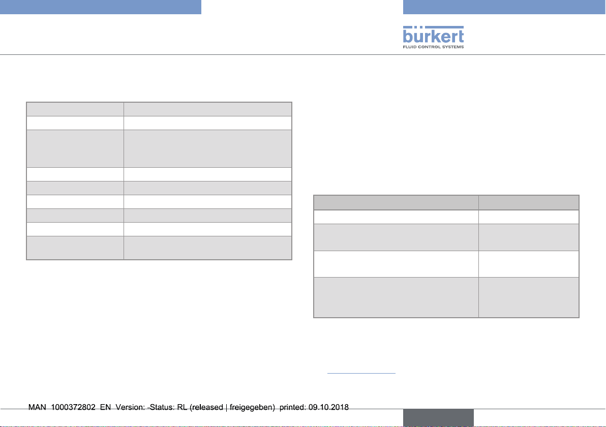
6.1 Conditions of use
Ambient temperature
Air humidity
Protection rating
according to
IEC / EN 60529
Operating conditions
Mobility of the device
Use
Degree of pollution
Installation category
Max. height above
sea level
–10...+60 °C
< 85%, non condensing
IP65 and IP67 with connectors plugged
in and tightened and electronic module
cover fully sealed
Continuous
Fixed
Indoor
Degree 2 according to UL / EN 61010-1
Category I according to UL / EN 61010-1
2000 m
6.2 Conformity to standards and directives
The applied standards, which verify conformity with the EU directives, can be found on the EU-type examination certificate and/or the
EU declaration of conformity (if applicable).
6.2.1 Conformity to the pressure equipment
directive
→ Make sure the device materials are compatible with the fluid.
→ Make sure the pipe DN and the nominal pressure PN are
adapted for the device.
Type 8026 flowmeter, Type S030, Type S070 and Type S077 fittings conform to Article 4, Paragraph 1 of the Pressure Equipment
Directive 2014/68/EU under the following conditions:
• Device used on a piping (PS = maximum admissible pressure;
DN = nominal diameter of the pipe)
Type of fluid Conditions
Fluid group 1, Article 4, Paragraph 1.c.i DN≤25
Fluid group 2, Article 4, Paragraph 1.c.i
Fluid group 1, Article 4, Paragraph 1.c.ii
Fluid group 2, Article 4, Paragraph 1.c.ii
DN≤32
or PSxDN≤1000
DN≤25
or PSxDN≤2000
DN≤200
or PS≤10
or PSxDN≤5000
6.3 Dimensions of devices
→ Please refer to the technical data sheets related to the device at:
www.burkert.com
English
9
Type 8026 - 8036 - SE36
Technical data
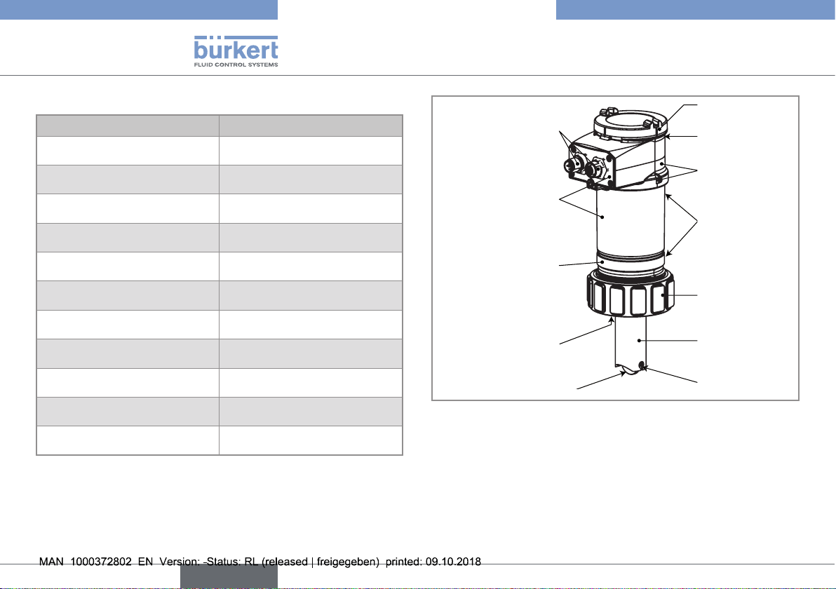
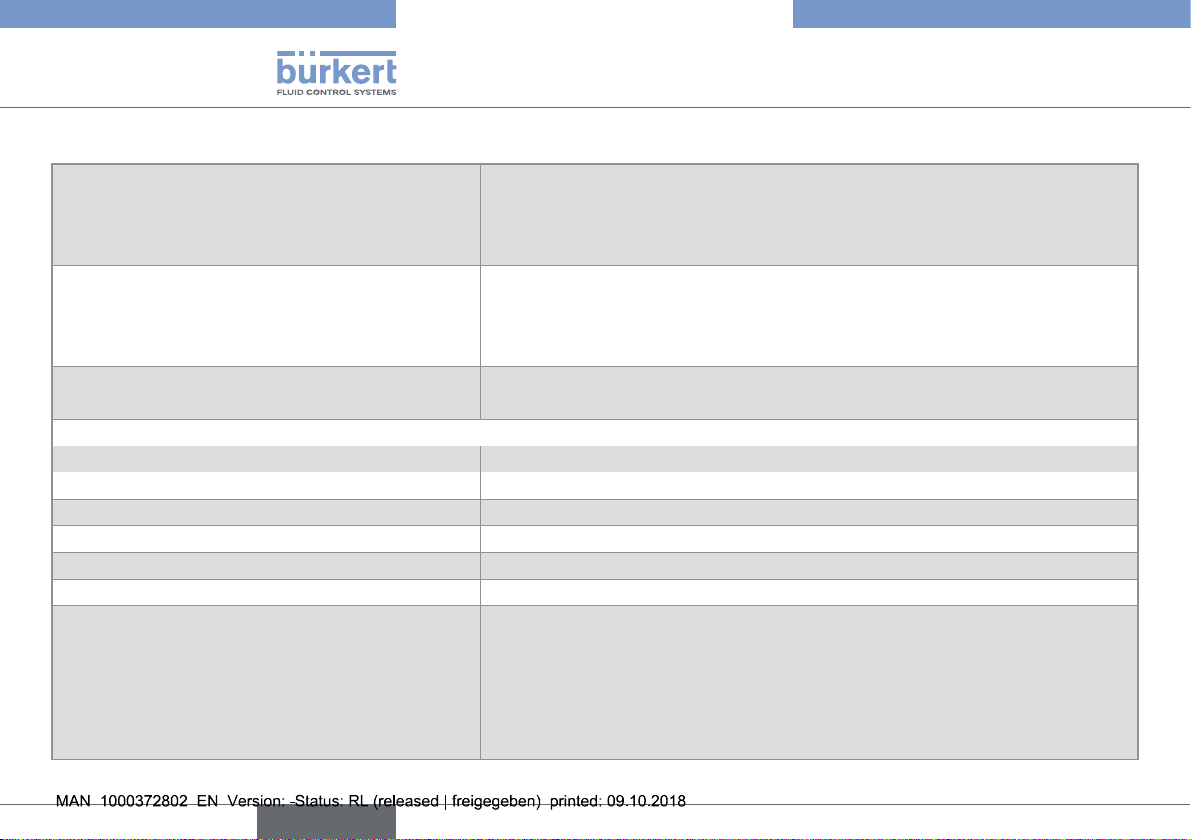
6.4 Materials
Part Material
Box / seals
Cover / seal PC / Silicone
Display module PC / PBT
M12 fixed connector
Fixed connector holder Stainless steel 1.4404 (316L)
Screws Stainless steel
Nut PC
Flow sensor holder / seal
(only 8026)
Axis and shaft of the paddle
wheel (only 8026)
Paddle wheel (only 8026) PVDF
Quarter-turn system (only SE36) PC
Stainless steel 1.4404,
PPS / EPDM
Nickel-plated brass
(stainless steel on request)
PVDF / FKM (default)
Ceramic (Al
2O3
)
PC
Nickel-plated brass
(or stainless steel)
Silicone
PPS
Stainless steel
EPDM
PPS
PC
FKM
PVDF
Fig. 2: Materials used in the flowmeter 8026
PVDF
Ceramic (Al
2O3
• Materials of the flowmeter 8026 in contact with the fluid: PVDF,
ceramic, FKM (default).
)
10
English
Type 8026 - 8036 - SE36
Technical data
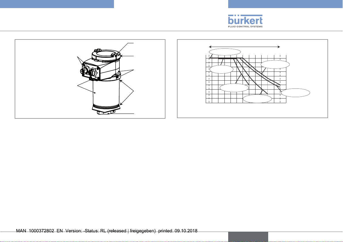
Nickel-plated brass
(or stainless steel)
Stainless steel
Fig. 3: Materials used in the flow transmitter SE36
PC
Silicone
PPS
EPDM
PC
A
P (bar)
10
9
8
7
6
5
4
3
2
1
0
A: Operating range
-10 +10 +30 +50 +70 +90 +110
PVDF +
PVC + PP
Metal
PVC (PN10)
PP (PN10)
Metal
(PN10)
PVDF (PN10)
T (°C)
Fig. 4: Fluid temperature / fluid pressure dependency for flowmeter 8026
associated to a fitting S020
English
11
Type 8026 - 8036 - SE36
Technical data
6.5 Fluid data
Pipe diameter
Type of fitting
Fluid temperature
• 8026
• 8036 • see the Operating Instructions, delivered with the fitting S030
• SE36 with a fitting S070 or S077 • see the Operating Instructions, delivered with the fitting S070 or S077
Fluid pressure
• 8026
• 8036 • see the Operating Instructions, delivered with the fitting S030
• SE36 with a fitting S070 or S077 • see the Operating Instructions, delivered with the fitting S070 or S077
Type of fluid
• 8026 and 8036 • Neutral or slightly aggressive fluids
• SE36 with fitting S070 or S077 • Viscous fluids, free of solid particles
Fluid viscosity
• 8026 and 8036 • 300 cSt max.
• SE36 with fitting S070 or S077 • see the Operating Instructions, delivered with the fitting S070 or S077
DN06 to DN400;
For fitting S020 or S030, the appropriate diameter is determined using the
flow rate / DN / fluid velocity graphs: refer to the Operating Instructions of the related fitting
• S020 for flowmeter 8026: see the Operating Instructions of the fitting
• S030 for flowmeter 8036: see the Operating Instructions of the fitting
• S070 or S077 for flow transmitter SE36: see the Operating Instructions of the fitting
• –15...+100 °C;
Also factor in the fluid temperature / fluid pressure dependency for the 8026 with fitting
S020: see Fig. 4
Also refer to the requirements of the Pressure Equipment Directive: see chap. 6.2.1
• PN10;
Also factor in the fluid temperature / fluid pressure dependency for the 8026 with fitting
S020: see Fig. 4
12
English
Type 8026 - 8036 - SE36
Technical data
Solid particle rate in the fluid
• 8026 and 8036 • ≤ 1 %
• SE36 with fitting S070 or S077 • 0 %
Flow rate measurement for 8026 and 8036
• Measurement range • 0.3...10 m/s
• Linearity • ±0.5 % of the full scale (10 m/s)
• Repeatability • ±0.4 % of the measured value
• Measurement deviation with standard K factor • ±2.5 % of the measured value
1)
1)
1)
• Measurement deviation with a Teach-in procedure • ±1 % of the measured value (at the value of the teach-in flow rate)
Flow rate measurement for SE36 with fitting S070 or S077
• Measurement range
- viscosity > 5 mPa.s - S070: 2...1200 I/min
- S077: 2...1200 I/min
- viscosity < 5 mPa.s - S070: 3...616 I/min
- S077: 3...616 I/min
• Measurement deviation
- with standard K-factor of the
sensor-fitting
- with K-factor determined with a teach-in
procedure or with the specific K-factor,
- S070: ±0.5 % of the measured value
- S077: ±1 % of the measured value
- S070: ±0.5 % of the measured value (at the value of the teach-in flow rate)
- S077: ±0.5 % of the measured value (at the value of the teach-in flow rate)
1)
1)
engraved on the fitting
1)
• Repeatability
• ±0.03 % of the measured value
1)
1)
1)
1)
Determined in the following reference conditions: fluid = water, water and ambiant temperatures = 20 °C, upstream and downstream dis-
tances respected, appropriate pipe dimensions.
English
13
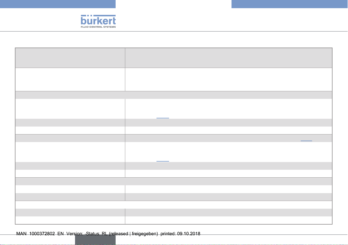
6.6 Electrical data
14...36 V DC power supply
version with 2 or 3 outputs (2 wires)
12...36 V DC power supply
version with 4 outputs (3 wires)
Specifications of the power source (not supplied)
of the UL devices
Current consumption
• version with 2 or 3 outputs (2 wires) • 25 mA max. (at 14 V DC)
• version with 4 outputs (3 wires) • 5 mA max. (at 12 V DC)
Current consumption, with loads on the transistors
Power consumption
Protection against polarity reversal
Protection against voltage spikes
Protection against short circuits
• Connection to main supply: permanent (through external SELV and through LPS
power supply)
• filtered and regulated
• oscillation rate: ±10 %
• Connection to main supply: permanent (through external SELV and through LPS
power supply)
• filtered and regulated
• oscillation rate: ±10 %
• Limited power source according to UL / EN 60950-1 standards
• or limited energy circuit according to UL / EN 61010-1, Paragraph 9.4
1 A max.
40 W max.
yes
yes
yes, transistor outputs
Type 8026 - 8036 - SE36
Technical data
14
English
 Loading...