

Page 1

BEDIENUNGSANLEITUNG 8025 UNIVERSAL ............................................... D-2
INSTRUCTION MANUAL 8025 UNIVERSAL .................................................. E-2
NOTICE D'UTILISATION 8025 UNIVERSAL ................................................... F-2
©BÜRKERT 1998 00555851 - Ind_D
Technische Änderungen vorbehalten
We reserve the right to make technical changes without notice
Sous réserve de modifications techniques
Page 2

INHALTSVERZEICHNIS
1 EINFÜHRUNG ............................................................................................................................... D-3
1.1 Auspacken und Kontrolle ......................................................................................................................... D-3
1.2 Allgemeine Hinweise ................................................................................................................................. D-3
1.3 Sicherheitshinweise ................................................................................................................................... D-3
1.4 Elektromagnetische Verträglichkeit ....................................................................................................... D-3
2 BESCHREIBUNG ..........................................................................................................................D-4
2.1 Transmitter Typenbezeichnung............................................................................................................... D-4
2.2 Durchfluss-Sensor Anschlussmöglichkeiten ...................................................................................... D-4
2.3 Aufbau und Messprinzip ........................................................................................................................... D-5
2.4 Abmessungen ............................................................................................................................................. D-6
2.5 Technische Daten ...................................................................................................................................... D-7
3 INSTALLATION ............................................................................................................................. D-9
3.1 Einbau ........................................................................................................................................................... D-9
3.1.1 Einbau der Schaltschrank-Ausführung ................................................................................... D-9
3.1.2 Einbau der Wandmontage-Ausführung............................................................................... D-10
3.2 Elektrischer Anschluss ........................................................................................................................... D-11
3.2.1 Allgemeine Hinweise zum elektrischen Anschluss........................................................... D-11
3.2.2 Einsatz der Kabelschellen ....................................................................................................... D-13
3.2.3 Einstellung des "SENSOR SUPPLY"-Schalters ............................................................... D-13
3.2.4 Einstellung der "FLOW SENSOR"- und "SENSOR INPUT LOAD"-Schalter .......... D-13
3.2.5 Elektrischer Anschluss, Schaltschrank-Ausführung, 13-30 VDC, ohne Relais ....... D-15
3.2.6 Elektrischer Anschluss, Schaltschrank-Ausführung, 13-30 VDC, mit Relais ........... D-17
3.2.7 Anschluss des Durchfluss-Sensors an den Transmitter 8025 Universal .................. D-18
3.2.8 Zuordnung der Kabelverschraubungen einer Wandmontage-Ausführung................ D-18
3.2.9 Elektrischer Anschluss, Wandmontage-Ausführung, 13-30 VDC .............................. D-19
3.2.10 Elektrischer Anschluss, Wandmontage-Ausführung, 115/230 VAC, ohne Relais . D-20
3.2.11 Elektrischer Anschluss, Wandmontage-Ausführung, 115/230 VAC, mit Relais ..... D-21
4 BEDIENUNG ............................................................................................................................... D-22
4.1 Bedien- und Anzeigeelemente des Transmitters ............................................................................ D-22
4.2 Normales Funktionsmenü ...................................................................................................................... D-23
4.3 Parametriermenü ..................................................................................................................................... D-23
4.3.1 Sprache ........................................................................................................................................ D-24
4.3.2 Einheiten ...................................................................................................................................... D-24
4.3.3 K-Faktor ....................................................................................................................................... D-25
4.3.4 Stromausgang ............................................................................................................................ D-26
4.3.5 Pulsausgang ............................................................................................................................... D-26
4.3.6 Relais ............................................................................................................................................ D-27
4.3.7 Filterfunktion und minimale Eingangsfrequenz .................................................................. D-28
4.3.8 Totalisator .................................................................................................................................... D-29
4.4 Testmenü ................................................................................................................................................... D-29
4.4.1 Offset-Abgleich ......................................................................................................................... D-29
4.4.2 Span-Abgleich ........................................................................................................................... D-30
4.4.3 Frequenzanzeige ........................................................................................................................ D-30
4.4.4 Durchfluss-Simulation .............................................................................................................. D-30
5 WARTUNG ................................................................................................................................... D-31
5.1 Hinweis Störung ...................................................................................................................................... D-31
5.2 Basis Einstellungen des 8025 bei Auslieferung ............................................................................. D-31
5.3 Maximalwerte zur Einstellung des Transmitters .............................................................................. D-31
5.4 Ersatzteil-Stückliste ................................................................................................................................ D-32
8025 UNIVERSAL
ANHANG ...................................................................................................................................... D-34
Durchfluss-Diagramme .......................................................................................................................... D-34
EG-Konformitätserklärung ..................................................................................................................... F-37
D-2-
Page 3

1 EINFÜHRUNG
Sehr geehrter Kunde,
8025 UNIVERSAL
LESEN SIE DIESE BEDIENUNGSANLEITUNG GRÜNDLICH, BEVOR SIE
DAS GERÄT MONTIEREN UND IN
BETRIEB NEHMEN.
1.1 Auspacken und Kontrolle
Bitte überprüfen Sie die Lieferung auf
Vollständigkeit und Transportschäden.
Um sicherzustellen, dass Sie das richtige
Gerät erhalten haben, vergleichen Sie die
Typenbezeichnung auf dem Typenschild
mit der nebenstehenden Liste. Bei Verlust
oder Schäden wenden Sie sich an Ihre
Bürkert Niederlassung.
1.2 Allgemeine Hinweise
Diese Druckschrift enthält keine
Garantiezusagen. Wir verweisen hierzu auf
unsere allgemeinen Verkaufs- und Lieferbedingungen.
Einbau und/oder Reparatur dürfen nur
durch eingewiesenes Personal erfolgen.
Sollten bei der Installation oder der
Inbetriebnahme Schwierigkeiten auftreten,
setzen Sie sich bitte sofort mit unserer
nächsten Niederlassung in Verbindung.
1.3 Sicherheitshinweise
Bürkert stellt verschiedene DurchflussTransmittern her. Jeder kann in einer Vielfalt
von Applikationen eingesetzt werden.
Gerne beraten wir hierzu intensiv. Es liegt
jedoch in der Verantwortung des Kunden,
das zu seiner Applikation optimal passende
Gerät zu wählen, es korrekt zu installieren
und instandzuhalten.
Dieses Symbol erscheint in der
Bedienungsanleitung jedesmal
wenn besondere Vorsicht
geboten ist, um eine
einwandfreie Installation,
Funktion und Betriebssicherheit
des Gerätes zu gewährleisten.
1.4 Elektromagnetische Verträglichkeit
Dieses Produkt erfüllt die grundlegenden
Anforderungen der Richtlinien
2004/108/EG (EMV) und 73/23/EG (DBT).
Dazu müssen die elektrischen Anschlussvorschriften befolgt werden.
Die Prüfung der Geräte wurde
entsprechend den folgenden EMV-Normen
durchgeführt:
- EN 61000-6-3
- EN 61000-6-2
- EN 61010-1
D-3-
Page 4

2 BESCHREIBUNG
8025 UNIVERSAL
2.1 Transmitter Typenbezeichnung
Durchfluss Transmitter 8025 "UNIVERSAL" Schaltschrank-Ausführung
Transmitter Spannung Bestell Nr.
4...20 mA, Impulsausgang, 2 Zähler, 2 Relais 13-30 VDC 419537
4...20 mA, Impulsausgang, 2 Zähler 13-30 VDC 419538
Durchfluss Transmitter 8025 "UNIVERSAL" Wandmontage-Ausführung
Transmitter Spannung Bestell Nr.
4...20 mA, Impulsausgang, 2 Zähler, 2 Relais 13-30 VDC 419540
4...20 mA, Impulsausgang, 2 Zähler 13-30 VDC 419541
4...20 mA, Impulsausgang, 2 Zähler, 2 Relais 115/230 VAC 419543
4...20 mA, Impulsausgang, 2 Zähler 115/230 VAC 419544
2.2 Durchfluss-Sensor Anschlussmöglichkeiten
Der Durchfluss Sensor, muss separat bestellt werden.
Der Transmitter 8025 Universal muss kann an folgenden Bürkert Sensoren mit
Frequenzausgang angeschlossen werden:
- 8030 standard, 8020 (Flügelrad aus PVDF mit integrierten Magneten)
- 8030 HT (Flügelrad aus Edelstahl)
- 8041 (Induktives Messprinzip) (außer 8025 Universal ref. 419543)
- 8039 (Optisches Messprinzip)
- 8071 (mit ovalen Rädern)
- 8031 (Turbine)
Bitte merken Sie sich:
- den Ausgangstyp, der Lastwiderstand und die Spannungsversorgung des Sensors, um
die Schalter des Transmitters 8025 korrekt zu positionnieren (siehe § 3.2.3 und 3.2.4)
- den K-Faktor des Sensors (vom Rohrdurchmesser abhängig) für die Kalibrierung des
Transmitters 8025 (siehe § 4.3.3).
D-4-
Page 5

2 BESCHREIBUNG
8025 UNIVERSAL
2.3 Aufbau und Messprinzip
Aufbau
Der Durchfluss-Transmitter für Schalttafeleinbau besteht aus einer Elektronik integriert im
Deckel.
Der elektrische Anschluss erfolgt über Klemmen.
Der Durchfluss-Transmitter für Wandmontage besteht aus einer Elektronik und einer
Anschlussplatine integriert in einem spritzwassergeschützten Kunststoffgehäuse in ABS,
Schutzart IP65.
Der elektrische Anschluss erfolgt über Klemmen durch drei Kabelverschraubungen.
Messprinzip
Der Sensor erzeugt durch die strömende Flüssigkeit eine durchflussproportionale
Messfrequenz.
Der Transmitter ist für einen Frequenzbereich von 0,5 oder 2,5 Hz bis 1400 Hz
entsprechend einem Durchfluss von 0,005 ml/s oder 0,025 ml/s bis zu
12884 l/s gültig. Als Ausgangssignal, steht ein eingeprägtes Normsignal 4...20 mA zur
Verfügung.
Der Messumformer ohne Relais benötigt zum Betrieb eine Spannungsversorgung von
13...30 VDC.
Der Transmitter in Wandmontage Ausführung kann mit einer optionellen
Spannungsversorgung 230/115 VAC ausgerüstet werden.
Die Grenzwerte der Messumformer mit 2 zusätzlichen Relais sind frei einstellbar.
D-5-
Page 6

2 BESCHREIBUNG
2.4 Abmessungen
Schaltschrank-Ausführung + Ausschneidschablone
38
88
76
25
8025 UNIVERSAL
95
80
76
50
88
Wandmontage-Ausführung
23
23
90
31.50
126
95
80
76
50
120
143
Fig. 2.1
Abdeckstreifen
3 Kabelverschraubungen
Abmessungen Durchfluss-Transmitter 8025 Universal
D-6-
Page 7

2 BESCHREIBUNG
8025 UNIVERSAL
2.5 Technische Daten
Umgebung
Umgebungstemperatur 0 bis 60 °C (Betriebs- und Lager)
Relative Feuchtigkeit max 80 %, nicht kondensierend
Schutzart IP 65 (Wandmontage und Deckel der Schaltschrank
Ausführung)
IP 20 (Schaltschrank-Ausführung, innerhalb des Schranks)
Werkstoffe
Gehäuse PC (Schaltschrank-Ausführung)
ABS (Wandmontage-Ausf.)
Deckel PC
Frontanzeige Polyester
Schrauben Edelstahl
Kabelverschraubungen PA
Kabelschellen PA
Elektrische Daten
Versorgungsspannung 13-30 VDC (L+) ± 10%, gefiltert u. geregelt, oder
115/230 VAC - 50/60 Hz (siehe technische
Angaben 115/230 VAC unten)
Umpolung geschützt
Stromaufnahme (Ohne Stromaufnahme des Pulsausgangs und der
Sensorversorgung):
≤ 70 mA, Ausführung mit Relais
≤ 30 mA, Ausführung ohne Relais
Stromausgang 4...20 mA, Strom- oder Senkemodus;
Max. Schleifenwiderstand:
1200 Ω bei 30 VDC; 900 Ω bei 24 VDC;
450 Ω bei 15 VDC; 300 Ω bei 13 VDC
1000 Ω bei einer 115/230 VAC-Versorgung
Pulsausgang polarisiert, potentialfrei, 5 - 30 VDC, 100 mA,
geschützt. Spannungsabfall bei 100 mA: 1,5 VDC
Relais-Ausgänge 2 Relais, 3 A, 230 VAC, frei einstellbar
2
Elektrische Verkabelung Durch abgeschirmtes Kabel, 1,5 mm
50 m max. Länge (Spannung, Puls- u. Strom-Ausgang)
2
max. Querschnitt (Relais)
1,5 mm
D-7-
max. Querschnitt,
Page 8

2 BESCHREIBUNG
Sensor-Anschluss
Signal Frequenz: 0,5 bis 1400 Hz oder 2,5 bis 1400 Hz,
einstellbar
Max. Spannung: 30 VDC
Pulstyp: Open Kollektor (NPN oder PNP), TTL,...
Sinustyp (Spule): Empfindlichkeit von typisch
80 mV Spitze-Spitze bei 250 Hz
Eingangsimpedanz je nach Position des "SENSOR INPUT LOAD"-
Auswahlschalters (siehe § 3.2.4)
Versorgung je nach Position des "SENSOR SUPPLY"-
Auswahlschalters:
5 VDC, max. 100 mA (Position 1)
12 VDC, max. 100 mA (Position 2)
11-28 VDC (L+ - 2 VDC), max. 100 mA (Position 3)
Technische Angaben, 115/230 VAC
Versorgte Spannung 27 VDC, geregelt
Max. Strom 250 mA
Integrierter Schutz Zeitsicherung von 250 mA
Leistung 6 VA
8025 UNIVERSAL
D-8-
Page 9

3 INSTALLATION
8025 UNIVERSAL
3.1 Einbau
Einbauvorschriften
Das Gerät muss vor dem Regen, vor Ultraviolettbestrahlung und
elektromagnetischen Störungen geschützt werden.
3.1.1 Schaltschrank-Ausführung (siehe Fig. 3.1)
Beachten Sie die in der Bedienungsanleitung des Sensors beschriebenen
Montageanweisungen. Dann bauen Sie das Gerät folgender Weise ein:
1. Für die Aussparung im Schaltschrank beachten Sie bitte die Anweisungen auf der
mitgelieferten Klebefolie. Achten Sie bitte genau auf die angegebenen Abmessungen.
2. Setzen Sie die Dichtung auf die Schrauben des Deckels auf.
Anmerkung: Bei einer zu dicken Schaltschrankwandung verwenden Sie bitte die 4
mitgelieferten M4x25 Schrauben.
3. Setzen Sie den Satz Deckel+Dichtung außerhalb des Schaltschranks auf die
Aussparung auf, Elektronikplatine nach Hinten.
4. Setzen Sie die 4 Scheiben auf die 4 Schrauben ein, dann befestigen Sie den
Transmitter mittels den 4 Bolzen an die Schaltschrankwandung.
5. Schließen Sie den Transmitter gemäß § 3.2 an.
6. Mittels den 4 mitgelieferten Kabelschellen die Kabel an die Schutzplatte befestigen.
Schraube
Kabelschelle
Fig. 3.1
Fächerscheibe
Bolzen
Dichtung
Einbau Schaltschrank- Ausführung
D-9-
Page 10

3 INSTALLATION
8025 UNIVERSAL
3.1.2 Wandmontage-Ausführung (siehe Fig. 3.2)
Beachten Sie die in der Bedienungsanleitung des abgesetzten Sensors beschriebenen
Montageanweisungen.
Der Transmitter für Wandmontage verfügt über 4 Befestigungsbohrungen im Gehäuse.
Die weißen Abdeckstreifen entfernen und Deckel öffnen, um an die Bohrungen zu
gelangen. Der Elektrische Anschluss ist in § 3.2. beschrieben.
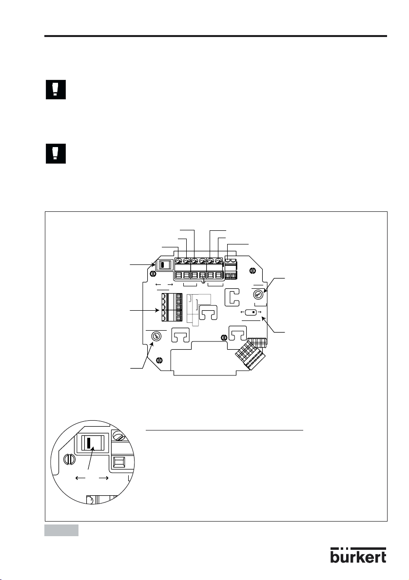
Fig. 3.2
Sicherung
SOURCE SINK
CURRENT
SENSOR SUPPLY
Iout L+ L-
FLOW SENSOR
1
+5V
2
+12V
3
L+
13..30Vdc
1
2
3
4
PE
Supply
PULSE INPUT
-
NC
+
NC
NC
COIL
REL2
PE
SUPPLY
NPN/PNP
3A/230VAC
P- P+
OUTPUT
PE PE
SENSOR
PULSE
INPUT LOAD
123
39K
470 2.2K
COIL
NPN
PNP
NPN
COIL
PNP
FLOW SENSOR
REL1
Einbau Wandmontage-Ausführung
Auswahl der Spannungsversorgung
115/230 V AC
230V
230V
230V
T 250 mA
LN
LN
5678910
D-10-
Page 11

3 INSTALLATION
8025 UNIVERSAL
3.2 Elektrischer Anschluss
3.2.1 Allgemeine Hinweise zum elektrischen Anschluss
● Das Gerät darf nicht bei angeschlossenem Netzkabel geöffnet werden.
● Die Anlage des Gebäudes, in dem der Transmitter installiert ist, muss
mit einem Schalter oder Überlastschalter gesichert sein. Dieser muss
ganz nah an dem Transmitter, zugänglich und als Schaltvorrichtung
für den Transmitter klar ausgezeichnet sein.
● Es ist ratsam, Sicherheitsvorrichtungen zu installieren:
Stromversorgung: Sicherung (300 mA- verzögert) und ein Schalter.
Relais: Höchstens 3 A-Sicherung und Überlastschalter (je nach
Anwendung).
● Setzen Sie nicht gleichzeitig im Selben Kabel eine gefährliche
Spannung und eine Sicherheits-Kleinspannung an die Relais an.
● Nur abgeschirmte Kabel mit einer Temperaturbeständigkeit bis mindestens 80°C
verwenden.
● Bei normalen Betriebsbedingungen kann das Messsignal über ein abgeschirmtes
Kabel mit einem Querschnitt von 0,75 mm2 übertragen werden.
● Die Signal-Leitung darf nicht in Kontakt mit stromführenden Leitungen mit höherer
Spannung oder Frequenz installiert werden.
● Wenn eine kombinierte Installation unumgänglich ist, sollten ein Mindestabstand
von 30 cm eingehalten werden.
● Bei Verwendung eines einzigen Kabels muss der Kabeldurchmesser zwischen 6 und
12 mm liegen; Wenn zwei Kabel gebraucht werden, setzen Sie die Mehrwegdichtung
ein und verwenden Sie Kabel mit einem 4-mm-Durchmesser.
● Es ist eine gefilterte und geregelte 13-30 VDC Stromversorgung zu verwenden.
● Vergewissern Sie die Äquipotentialität der Installation (Stromversorgung - Transmitter
- Flüssigkeit):
-Die verschiedene Erdungspunkte der Installation müssen aneinander
angeschlossen sein, damit die zwischen zwei Erdungspunkten
möglicherweise erzeugten Potentialdifferenzen beseitigt werden.
-Es muss auf vorschriftsmäßige Erdung der Abschirmung geachtet werden.
-Erden Sie den negativen Anschluss der Versorgungsquelle, um
Gleichtaktströme zu unterdrücken. Ist eine direkte Erdung unmöglich,
schließen Sie ein 100 nF/50 V-Kondensator zwischen dem negativen Anschluss
der Versorgungsquelle und der Erde.
Geben Sie darauf besonders acht, wenn das Gerät auf Kunststoffrohren installiert
wird, weil keine direkte Erdung möglich ist.
Zur Ordnungsgemäßen Erdung müssen alle die sich in der Nähe des Geräts
befindenden metallischen Apparate, wie Ventile oder Pumpen, an den selben
Erdungspunkt angeschlossen werden.
D-11-
Page 12
3 INSTALLATION
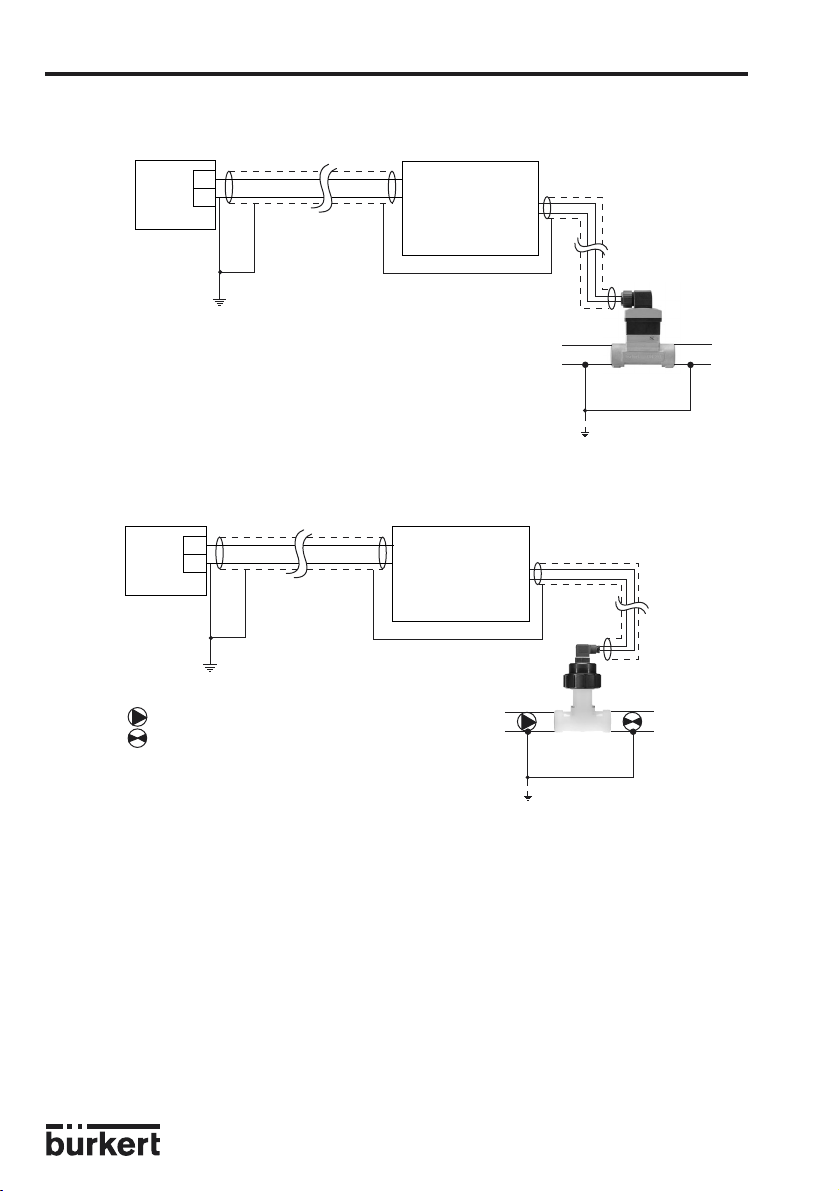
Prinzipschaltbild einer Äquipotentialität
8025 UNIVERSAL
Versorgung
Versorgung
Geräte wie Ventil,
Pumpe, usw...
+
-
(*)
8025
Wandmontageoder
SchaltschrankAusführung
8030
Metallische Rohre
+
-
(*)
8025
Wandmontageoder
SchaltschrankAusführung
8020
Kunststoffrohre
(*) ist keine direkte Erdung möglich, schließen Sie einen 100 nF/50V-Kondensator zwischen dem negativen
Anschluss der Versorgungsquelle und der Erde an.
D-12-
Page 13
3 INSTALLATION
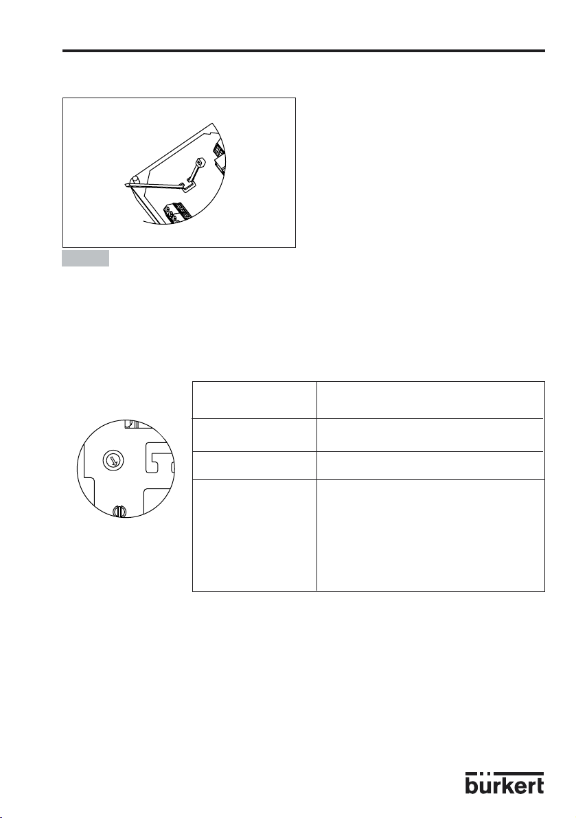
3.2.2 Einsatz der Kabelschellen
8025 UNIVERSAL
Bevor Sie das Gerät verkabeln, fädeln Sie
die mitgelieferten Kabelschellen in
Elektronikplatine bzw. 115/230 VACVersorgungsplatine, wenn vorhanden, ein.
Fig. 3.3
Einsatz der Kabelschellen
3.2.3 Einstellung des "SENSOR SUPPLY"-Schalters
Bevor Sie das Gerät verkabeln, überprüfen Sie bitte die korrekte Einstellung der Schalter
der Elektronikplatine des 8025 Universal.
SENSOR SUPPLY dem abgesetzten Sensor
Schalter versorgte Spannung
FLOW SENSOR
SENSOR SUPPLY
1
2
3
+5V
+12V
L+
Position 1 +5 VDC
Position 2 +12 VDC
Position 3 - entweder +27 VDC (bei einer
115/230 VAC-Versorgung des
8025 Universal)
- oder = Versorgungsspannung des
8025 Universal (bei einer 13-30 VDC
Versorgung des 8025 Universal)
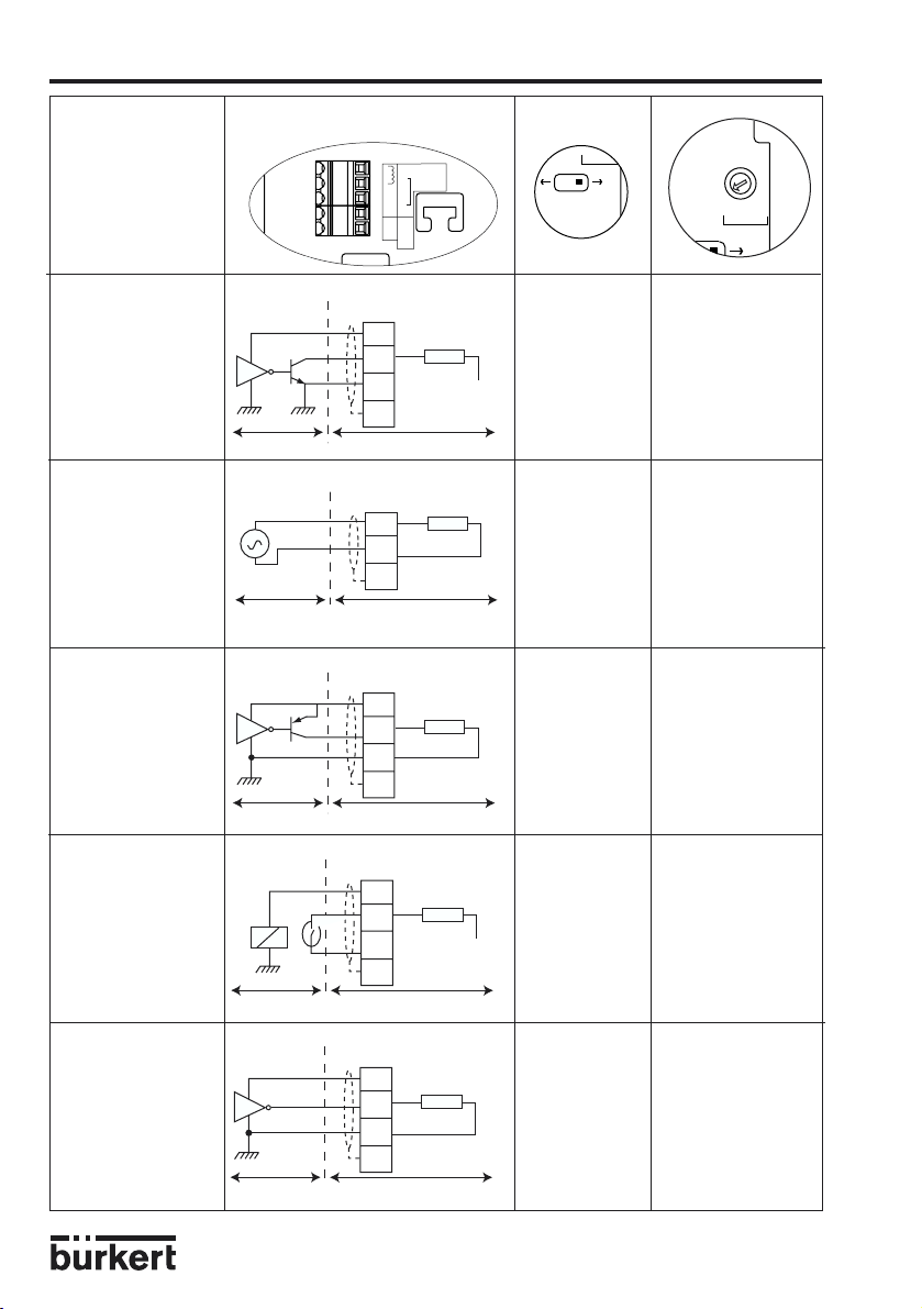
3.2.4 Einstellung der "FLOW SENSOR"- und "SENSOR INPUT LOAD"-Schalter
Bevor Sie das Gerät verkabeln, überprüfen Sie bitte die korrekte Einstellung der Schalter
der Elektronikplatine des 8025 Universal. Der "FLOW SENSOR"-Schalter entspricht dem
Typ des Sensors und der "SENSOR INPUT LOAD"-Schalter dem Typ des
Sensorausgangs.
D-13-
Page 14
3 INSTALLATION
FLOW SENSOR
COIL NPN/PNP
COIL
PNP
470 2.2
NPN
2
8025 UNIVERSAL
Ausgangssignal Anschluss des abgesetzten
des abgesetzten Sensors an den 8025 Universal
Sensors
FLOW SENSOR
UPPLY
Puls, NPN NPN/PNP - Position 1 (bei einem
SENSOR
Sinus (Spule) COIL Position 3
SENSOR
Supply
13..30Vdc
1
PULSE INPUT
SUPPLY
2
-
NC
3
+
NC
NC
4
PE
COIL
NPN/PNP
L2
Klemmen
"FLOW SENSOR"
3
1
2
PE
8025 UNIVERSAL
Klemmen
"FLOW SENSOR"
1
39 kΩ
2
PE
8025 UNIVERSAL
SENSOR INPUT
LOAD
1
3
39K
2
COIL
470 2.2K
PNP
NPN
Lastwiderstand
R
+5 V
R = 2,2 kΩ)
- Position 2 (bei einem
Lastwiderstand
R = 470 Ω)
(39 kΩ−-
Eingangsimpedanz)
Puls, PNP NPN/PNP Position 3
Klemmen
"FLOW SENSOR"
3
39 kΩ
(39 kΩ−-
Eingangsimpedanz)
1
2
PE
SENSOR
Ein-/Aus-Kontakt NPN/PNP - Position 1 (bei einem
(Reed-Relais, Lastwiderstand
zum Beispiel) R = 2,2 kΩ)
SENSOR
Normspannung NPN/PNP Position 3
0-5 VDC (39 kΩ−
(TTL, zum Beispiel) Eingangsimpedanz)
8025 UNIVERSAL
Klemmen
"FLOW SENSOR"
...
8025 UNIVERSAL
"FLOW SENSOR"
3
1
2
PE
Klemmen
3
1
R
39 kΩ
+5 V
- Position 2 (bei einem
Lastwiderstand
R = 470 Ω)
2
PE
8025 UNIVERSAL
D-14-
SENSOR
Page 15
3 INSTALLATION
8025 UNIVERSAL
3.2.5 Elektrischer Anschluss, Schaltschrank-Ausführung, 13-30 VDC,
ohne Relais
Bevor Sie das Gerät verkabeln, lesen Sie bitte § 3.2.1, 3.2.2, 3.2.3, 3.2.4
und 3.2.7.
Bauen Sie das Gerät in den Schaltschrank gemäß Einbauvorschriften des § 3.1.1.
Anschließend Kabel laut folgende Anschlusspläne anklemmen.
- Schalter nicht unter Spannung einstellen!
- Vergewissern Sie sich, dass Schalter "SENSOR SUPPLY", "FLOW
SENSOR" und "SENSOR INPUT LOAD" (siehe § 3.2.3 und 3.2..4) richtig
eingestellt sind, entsprechend der getrennten Sensor-Ausführung.
L+ (13-30 VDC)
4-20 mA-Ausgang
Schalter [1] :
siehe unten
Anschluss des getrennten
Durchfluss-Sensors: siehe
§ 3.2.7
"Dem getrennten Sensor
versorgte Spannung"-Schalter:
siehe § 3.2.3
SOURCE SINK
CURRENT
Iout
L- (0V)
Pulsausgang 팫
Pulsausgang 팬
Abschirmung der Versorgungs- und
Pulsausgangskabeln verbinden
SOURCE SINK
CURRENT
SENSOR SUPPLY
Iout L+ L-
FLOW SENSOR
1
+5V
2
+12V
3
L+
Supply
13..30Vdc
1
2
3
4
PE
PULSE INPUT
-
NC
+
NC
NC
COIL
NPN/PNP
REL2
P- P+
PE
SUPPLY
3A/230VAC
PULSE
OUTPUT
PE PE
REL1
COIL
FLOW SENSOR
39K
COIL
PNP
SENSOR
INPUT LOAD
470
"Lastwiderstand des getrennten
Sensors"-Schalter: siehe § 3.2.4
123
2.2K
NPN
NPN
PNP
"Typ des getrennten Sensors"Schalter: siehe § 3.2.4
Schalter [1], "Anschlussmodus des Stromausgangs":
- In Position "SOURCE", wenn der 4-20 mA-Ausgang an eine SPS als Quelle
ansgeschlossen ist.
- In Position "SINK", wenn der 4-20 mA-Ausgang an eine SPS als Senke
ansgeschlossen ist.
Fig. 3.4
Anschluss 8025 Universal, Schaltschrank-Ausführung, 13-30 VDC, ohne Relais
D-15-
Page 16

3 INSTALLATION
8025 UNIVERSAL
Anschluss des Schaltschrank-Transmitters 8025 Universal, 13-30 VDC, an eine SPS
Die 4-20 mA- und Puls-Ausgänge des Transmitters, 13-30 VDC können an eine SPS
angeschlossen werden. Entsprechend der SPS-Ausführung und dem Anschlussmodus
des 4-20 mA-Ausgangs muss der Schalter [1] auf der Platine in Position "SOURCE"
(Quelle Modus) oder in Position "SINK" (Senke Modus) gestellt werden (siehe folgende
Fig. und Fig. 3.4).
Anschluss des 4-20 mA-Ausgangs des
Transmitters 8025 als Quelle
4-20 mA
Schalter [1]
(siehe
Fig. 3.4)
SOURCE SINK
CURRENT
300 mA
+
-
Iout
Iout L+ L-
Supply
13..30Vdc
PE
P- P+
OUTPUT
PULSE
+
-
13-30 VDC
(*)
PE PE
INPUT LOAD
SENSOR
Anschluss des Pulsausgangs des 8025,
verkabelt in NPN Modus
13-30 VDC
Versorg.
300 mA
+
-
(*)
+
5-30 VDC
-
+
-
Anschluss des 4-20 mA-Ausgangs des
Transmitters 8025 als Senke
4-20 mA
Schalter [1]
(siehe
Fig. 3.4)
SOURCE SINK
CURRENT
300 mA
+
-
Iout
Iout L+ L-
13..30Vdc
+
-
13-30 VDC
PE PE
P- P+
PE
Supply
PULSE
OUTPUT
Anschluss des Pulsausgangs des 8025,
verkabelt in PNP Modus
+
5-30 VDC
-
+
-
SPS
13-30 VDC
Versorg.
+
300 mA
-
(*)
(*)
SENSOR
INPUT LOAD
SPS
SOURCE SINK
CURRENT
Iout L+ L-
Supply
13..30Vdc
PE PE
P- P+
PE
PULSE
OUTPUT
P-
8025:
NPN
SENSOR
INPUT LOAD
P+
SOURCE SINK
CURRENT
Iout L+ L-
Supply
13..30Vdc
PE PE
P- P+
PE
PULSE
OUTPUT
P-
8025:
PNP
SENSOR
INPUT LOAD
P+
(*) ist keine direkte Erdung möglich, schließen Sie einen 100 nF/50V-Kondensator zwischen dem negativen
Anschluss der Versorgungsquelle und der Erde an.
Fig. 3.5
Anschluss des Transmitters 8025 Universal, 13-30 VDC, an eine SPS
D-16-
Page 17

3 INSTALLATION
8025 UNIVERSAL
3.2.6 Elektrischer Anschluss, Schaltschrank-Ausführung, 13-30 VDC,
mit Relais
Bevor Sie das Gerät verkabeln, lesen Sie bitte § 3.2.1, 3.2.2, 3.2.3, 3.2.4
und 3.2.7.
Bauen Sie das Gerät in den Schaltschrank gemäß Einbauvorschriften des § 3.1.1.
Anschließend Kabel laut folgende Anschlusspläne anklemmen.
- Schalter nicht unter Spannung einstellen!
- Vergewissern Sie sich, dass Schalter "SENSOR SUPPLY", "FLOW
SENSOR" und "SENSOR INPUT LOAD" (siehe § 3.2.3 und 3.2..4) richtig
eingestellt sind, entsprechend der getrennten Sensor-Ausführung.
Pulsausgang 팫
Pulsausgang 팬
Abschirmung der Versorgungs- und
Pulsausgangskabeln verbinden
4-20 mA-Ausgang
Schalter [1]:
L+ (13-30 VDC)
L- (0V)
siehe Fig. 3.4
"Lastwiderstand des getrennten
Sensors"-Schalter: siehe § 3.2.4
123
2.2K
NPN
PNP
"Typ des getrennten Sensors"Schalter: siehe § 3.2.4
Anschluss des getrennten
Durchfluss-Sensors: siehe
§ 3.2.7
"Dem getrennten Sensor
versorgte Spannung"-
SOURCE SINK
CURRENT
SENSOR SUPPLY
Iout L+ L-
FLOW SENSOR
1
+5V
2
+12V
3
L+
Supply
13..30Vdc
1
2
3
4
PE
PULSE INPUT
-
NC
+
NC
NC
COIL
NPN/PNP
REL2
P- P+
PE
SUPPLY
3A/230VAC
PULSE
OUTPUT
PE PE
REL1
COIL
FLOW SENSOR
39K
COIL
PNP
SENSOR
INPUT LOAD
470
NPN
Schalter: siehe § 3.2.3
+
-
+
-
Anschluss Relais 1
an Typ 142
Anschluss Relais 2
an Typ 121
Relais-Kabel obligatorisch mittels mitgelieferten
Kabelschellen befestigen (siehe § 3.2.2)
Fig. 3.6
Anschluss 8025 Universal, Schaltschrank-Ausführung, 13-30 VDC, und AnschlussBeispiel für die Relais
Anschluss des Schaltschrank-Transmitters 8025 Universal, 13-30 VDC, mit Relais
an eine SPS
Die Anschlüsse der Strom- bzw. Pulsausgänge des 8025 Universal, SchaltschrankAusführung, 13-30 VDC, mit Relais erfolgen wie diejenigen der SchaltschrankAusführung, 13-30 VDC, ohne Relais (siehe Fig. 3.5, § 3.2.5).
D-17-
Page 18

3 INSTALLATION
8025 UNIVERSAL
3.2.7 Anschluss des Durchfluss-Sensors an den Transmitter 8025 Universal
Schließen Sie den getrennten Durchfluss-Sensor an die FLOW SENSOR-Klemmen der
Elektronikplatine, gemäß der Anschlussbelegung je nach Sensor-Ausführung, entweder
mit Sinus- (COIL) bzw. Puls-Ausgang, an. Zuvor müssen die Schalter der Elektronikplatine
richtig eingestellt werden (siehe § 3.2.3 und 3.2.4).
1
2
{
3
NC
4
FLOW SENSOR
PE
Abschirmung des Sensorkabels verbinden Abschirmung des Sensorkabels verbinden
FLOW SENSOR
1
2
3
4
NC
PE
Puls
L+5 VDC, +12 VDC oder L+ (je
nach Auswahl des "SENSOR
SUPPLY"-Schalters)
Sensor mit Sinusausgang Sensor mit Pulsausgang
NC = Nicht belegt
3.2.8 Zuordnung der Kabelverschraubungen einer WandmontageAusführung
Kabel durch die Kabelverschraubungen ziehen. Folgen Sie bitte folgende Zuordnung der
Verschraubungen, um die Verkabelung der Wandmontage-Ausführung zu erleichtern.
Ausgänge-Kabel
DurchflussSensor-Kabel
13-30 VDC oder
115/230 VAC
Versorgungskabel
Fig. 3.7
Zuordnung der Kabelverschraubungen, Wandmontage-Ausführung
D-18-
Page 19

3 INSTALLATION
8025 UNIVERSAL
3.2.9 Elektrischer Anschluss Wandmontage-Transmitter, 13-30 VDC,
ohne oder mit Relais
Bevor Sie das Gerät verkabeln, lesen Sie bitte § 3.2.1, 3.2.2, 3.2.3, 3.2.4
und 3.2.7.
Bauen Sie das Gerät gemäß Einbauvorschriften des § 3.1.2 an. Die vier Schrauben lösen
und den Deckel öffnen. Kabelverschraubungen aufschrauben.
Folgen Sie bitte die in § 3.2.8 angegebene Zuordnung der Verschraubungen.
Anschließend Kabel laut folgende Anschlusspläne anklemmen.
- Schalter nicht unter Spannung einstellen!
- Vergewissern Sie sich, dass Schalter "SENSOR SUPPLY", "FLOW
SENSOR" und "SENSOR INPUT LOAD" (siehe § 3.2.3 und 3.2.4) richtig
eingestellt sind, entsprechend der getrennten Sensor-Ausführung.
Pulsausgan 팫
PE
P- P+
PULSE
OUTPUT
Pulsausgan 팬
Abschirmung der Versorgungs- und
Pulsausgangskabeln verbinden
PE PE
SENSOR
INPUT LOAD
123
39K
2.2K
470
COIL
PNP
NPN
NPN
COIL
PNP
FLOW SENSOR
REL1
"Lastwiderstand des getrennten
Sensors"-Schalter: siehe § 3.2.4
"Typ des getrennten Sensors"Schalter: siehe § 3.2.4
L+ (13-30 VDC)
4-20 mA-Ausgang
Schalter [1]:
siehe Fig. 3.4
Anschluss des
getrennten DurchflussSensors: siehe § 3.2.7
L- (0V)
SOURCE SINK
CURRENT
SENSOR SUPPLY
Iout L+ L-
FLOW SENSOR
1
+5V
2
+12V
3
L+
Supply
13..30Vdc
1
2
3
4
PE
PULSE INPUT
-
NC
+
NC
NC
COIL
REL2
SUPPLY
NPN/PNP
3A/230VAC
"Dem getrennten
Sensor versorgte Spannung"Schalter: siehe § 3.2.3
Anschluss der Relais
(je nach Ausführung, siehe beispiel Fig 3.6)
Relais-Kabel obligatorisch mittels mitgelieferten
Kabelschellen befestigen (siehe § 3.2.2)
Fig. 3.8
Anschluss 8025 Universal, Wandmontage-Ausführung, 13-30 VDC
Anschluss des Transmitters 8025 Universal, 13-30 VDC, an eine SPS
Die Anschlüsse der Strom- bzw. Pulsausgänge des 8025 Universal, WandmontageAusführung, 13-30 VDC, ohne oder mit Relais erfolgen wie diejenigen der SchaltschrankAusführung, 13-30 VDC (siehe Fig. 3.5, § 3.2.5).
D-19-
Page 20

3 INSTALLATION
8025 UNIVERSAL
3.2.10 Elektrischer Anschluss Wandmontage-Transmitter, 115/230 VAC,
ohne Relais
Bevor Sie das Gerät verkabeln, lesen Sie bitte § 3.2.1, 3.2.2, 3.2.3, 3.2.4
und 3.2.7.
Bauen Sie das Gerät gemäß Einbauvorschriften des § 3.1.2 an. Die vier Schrauben lösen
und den Deckel öffnen. Kabelverschraubungen aufschrauben.
Folgen Sie bitte die in § 3.2.8 angegebene Zuordnung der Verschraubungen.
Anschließend Kabel laut folgende Anschlusspläne anklemmen.
- Schalter nicht unter Spannung einstellen!
- Vergewissern Sie sich, dass Schalter "SENSOR SUPPLY", "FLOW
SENSOR" und "SENSOR INPUT LOAD" (siehe § 3.2.3 und 3.2.4) richtig
eingestellt sind, entsprechend der getrennten Sensor-Ausführung.
PE
SUPPLY
NPN/PNP
3A/230VAC
P- P+
PULSE
OUTPUT
Durchgeschleifte
Abschirmung*
PE PE
SENSOR
INPUT LOAD
123
39K
2.2K
470
COIL
PNP
NPN
NPN
COIL
PNP
FLOW SENSOR
REL1
Sicherung
T 250 mA
5678910
115 VAC oder 230 VACAuswahlschalter
230V
230V
230V
LN
LN
{
Weißer Draht* P+
Brauner Draht* P-
Schwarzer Draht* L-
Roter Draht * L+
Grüner Draht * 4-20 mA
Schalter [1]:
siehe Fig. 3.4
Anschluss des
getrennten
DurchflussSensors: siehe
SENSOR SUPPLY
§ 3.2.7
SOURCE SINK
CURRENT
FLOW SENSOR
1
+5V
2
+12V
3
L+
Iout L+ L-
Supply
13..30Vdc
1
2
3
4
PE
PULSE INPUT
-
NC
+
NC
NC
COIL
REL2
* im Werk verdrahtet
Fig. 3.9
Anschluss 8025 Universal, Wandmontage-Ausführung, 115/230 VAC, ohne Relais
Alle Kabel hier befestigen
Anschluss des 4-20 mA-Ausgangs des 8025
an eine SPS: siehe § 3.2.11, Fig. 3.10
Abschirmung der Ausgangskabeln
verbinden
+
5-30 VDC
-
+
-
Anschluss des Pulsausgangs des 8025,
verkabelt in NPN Modus an eine SPS
D-20-
Anschluss der
115/230 VACVersorgung
Iout
L+
L-
P-
P+
P-
P+
+
5-30 VDC
-
+
-
Anschluss des Pulsausgangs des 8025,
verkabelt in PNP Modus an eine SPS
Page 21

3 INSTALLATION
8025 UNIVERSAL
3.2.11 Elektrischer Anschluss Wandmontage-Transmitter, 115/230 VAC,
mit Relais
Bevor Sie das Gerät verkabeln, lesen Sie bitte § 3.2.1, 3.2.2, 3.2.3, 3.2.4
und 3.2.7.
Bauen Sie das Gerät gemäß Einbauvorschriften des § 3.1.2 an. Die vier Schrauben lösen
und den Deckel öffnen. Kabelverschraubungen aufschrauben.
Folgen Sie bitte die in § 3.2.8 angegebene Zuordnung der Verschraubungen.
Anschließend Kabel laut folgende Anschlusspläne anklemmen.
- Schalter nicht unter Spannung einstellen!
- Vergewissern Sie sich, dass Schalter "SENSOR SUPPLY", "FLOW
SENSOR" und "SENSOR INPUT LOAD" (siehe § 3.2.3 und 3.2.4) richtig
eingestellt sind, entsprechend der getrennten Sensor-Ausführung.
Weißer Draht* P+
Brauner Draht* P-
Schwarzer Draht* L-
Roter Draht * L+
Grüner Draht * 4-20 mA
Durchgeschleifte
Abschirmung*
Schalter [1]:
siehe Fig. 3.4
Anschluss des
getrennten
DurchflussSensors: siehe
§ 3.2.7
SOURCE SINK
CURRENT
SENSOR SUPPLY
Iout L+ L-
FLOW SENSOR
1
+5V
2
+12V
3
L+
Supply
13..30Vdc
1
2
3
4
PE
NC
NC
COIL
PE
PULSE INPUT
SUPPLY
-
+
NC
NPN/PNP
REL2
3A/230VAC
P- P+
PULSE
OUTPUT
PE PE
REL1
COIL
FLOW SENSOR
39K
COIL
PNP
* im Werk verdrahtet
{
Relais 2 Relais 1
(siehe Beispiel Fig. 3.6)
{
Relais-Kabel obligatorisch mittels mitgelieferten
Kabelschellen befestigen (siehe § 3.2.2)
L+
-
+
4-20 mA
Anschluss des 4-20 mA-Ausgangs
des 8025 als Senke an eine SPS
Iout
L-
Iout
Iout
-
+
4-20 mA
Anschluss des 4-20 mA-Ausgangs
des 8025 als Quelle an eine SPS
SENSOR
INPUT LOAD
123
2.2K
470
NPN
NPN
PNP
Alle Kabel hier
befestigen
Abschirmung der
Ausgangskabeln
verbinden
Sicherung
T 250 mA
5678910
115 VAC oder 230 VACAuswahlschalter
230V
230V
230V
LN
LN
{
Anschluss der
115/230 VACVersorgung
P-
P+
Anschluss des Pulsausgangs
des 8025 an eine SPS:
siehe § 3.2.10 Fig. 3.9
Fig. 3.10
Anschluss 8025 Universal, Wandmontage-Ausführung, 115/230 VAC, mit Relais
D-21-
Page 22

4 BEDIENUNG
8025 UNIVERSAL
Die Bedienung gliedert sich in 3 Ebenen.
A) Anzeigen
Hier werden der Durchfluss, der Ausgangsstrom, der Haupttotalisator und
Tagestotalisator angezeigt. In diesem Menü wird auch der Tagestotalisator zurückgestellt.
B) Parametrieren
Hier werden alle notwendigen Einstellungen (Sprache, Einheiten, K-Faktor, 4...20 mA
Messbereich, Pulsausgang, Relais, Filter) durchgeführt.
Hier werden auch der Haupttotalisator und der Tagestotalisator gleichzeitig zurückgestellt.
C) Testen
In diesem Menü kann ein Durchfluss simuliert werden. Es ermöglicht einen Prozess "im
trockenen Zustand" zu testen.
Hier wird auch die Frequenz des Sensors angezeigt.
Hier können die Grundeinstellungen (Offset, Span) des Gerätes verändert werden.
4.1 Bedien- und Anzeigeelemente des Transmitters
Inkrementiertaste
Zahlenwert je Stelle
verändern von 0 bis 9
Menü durchlaufen
(Numerische Werte)
Wahltaste
Stelle auswählen
Menü durchlaufen
Relais 1 Status
D-22-
Bestätigungstaste
Eingabe und Menüpunkte
Relais 2 Status
Page 23

4 BEDIENUNG
.
4.2 Normales Funtionsmenü
Im normalen Funktionsmenü werden folgende Grössen angezeigt:
8025 UNIVERSAL
45,6 L/m
16,45
0......9
80529 L
6247 L
4.3 Parametriermenü: gleichzeitig während 5 Sekunden
Im Parametriermenü werden folgende Grössen eingestellt:
SPRACHE
EINHEIT
K-FAKTOR
STROM
Durchfluss in der gewünschten Einheit (siehe Kalibrationsmenü).
Ausgangssignal 4...20 mA proportional zum Durchfluss
mA
entsprechend dem gewählten Messbereich
Haupttotalisator in der gewünschten Einheit (siehe
Kalibrationsmenü). Wird im Kalibrationsmenü zurückgestellt.
Tagestotalisator in der selben Einheit wie der Haupttotalisator.
Er unterscheidet sich von dem anderen durch einen Punkt nach
der Einheit. Wird mit gleichzeitigem Drücken, während 2
Sekunden, der Tasten zurückgestellt.
ENTER
Auswahl der Sprache zwischen deutsch, englisch, französisch
und italienisch.
Auswahl der Einheit für die Durchfussanzeige und den
Totalisator.
Eingabe des K-Faktors aus Tabelle oder Teach-in Funktion zur
Bestimmung des spezifischen K-Faktors.
Festlegung des 4...20 mA Messbereiches.
0......9
0......9
PULS
RELAIS
FILTER
TOTAL
ENDE
Parametrierung des Pulsausgangs (Einheit und Menge).
Parametrierung der Relais. Diese Meldung erscheint nicht wenn
die Option Relais nicht gerüstet ist.
Auswahl der Dämpfung. Zwei Filtertypen mit jeweils 10
Dämpfungsstufen stehen zur Verfügung.
Auswhal der min. Eingangsfrequenz.
Rückstellung der Totalisatoren.
Zurück ins Funktionsmenü und Speicherung der neuen
Parameter.
D-23-
Page 24

4 BEDIENUNG
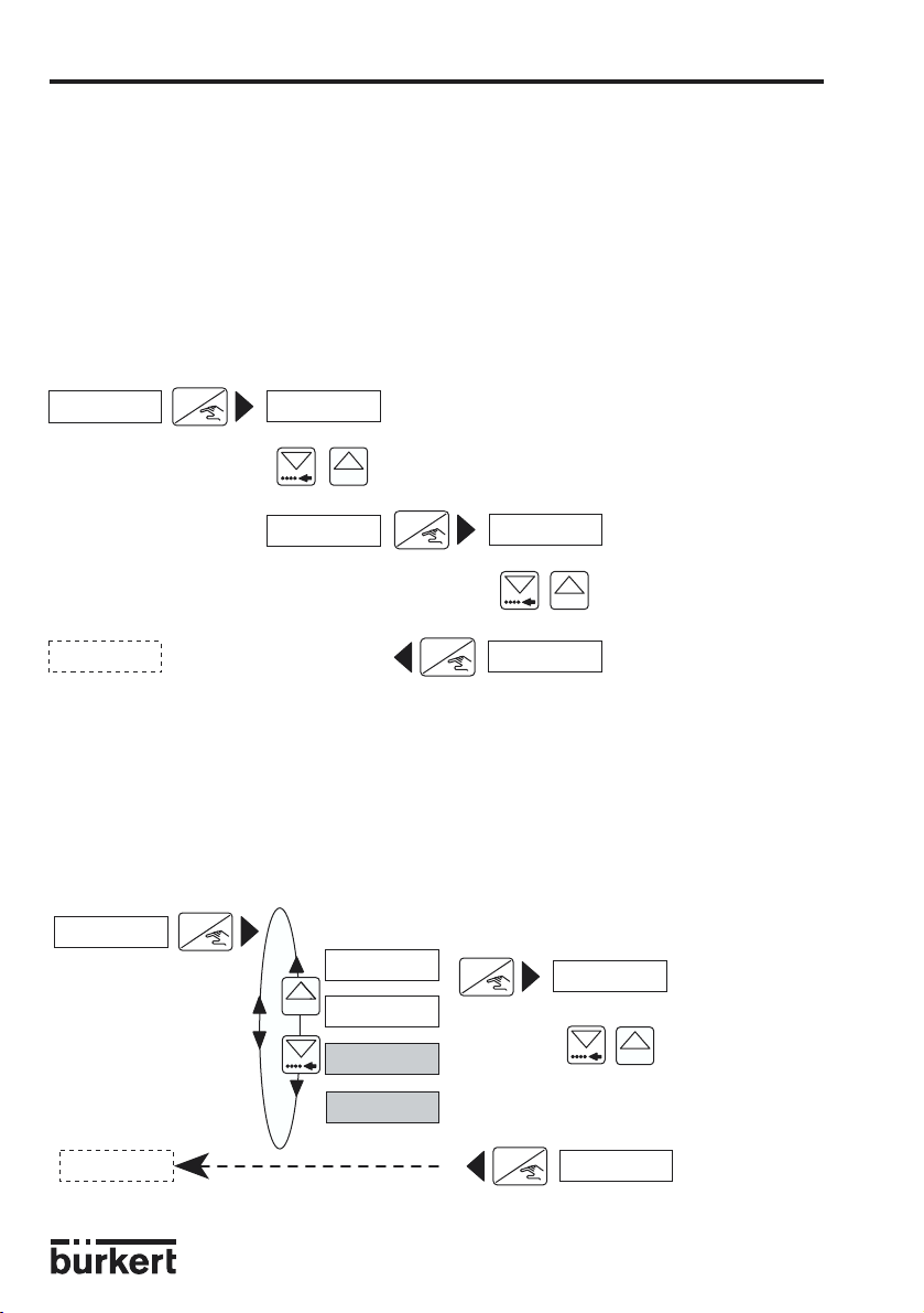
4.3.1 Sprache
ENTER
LANGUAGE
0......9
ENGLISH
DEUTSCH
FRANCAIS
8025 UNIVERSAL
Die gewünschte Sprache wird
durch die Entertaste bestätigt und
dabei gleich aktiv.
UNIT
4.3.2 Einheiten
EINHEIT
ENTER
ENTER
DURCHFLU
0......9
TOTAL
ITALIANO
0......9
m LIT/SEC
m
LIT/MIN
m
LIT/H
LIT/SEC
LIT/MIN
LIT/H
M3/MIN
M3/H
US GAL/S
US GAL/M
US GAL/H
IMP GA/S
IMP GA/M
IMP GAL/H
m
LITER
ENTER
Falls metrische Einheiten
ENTER
Der Durchfluss kann in
jeder Einheit mit 0, 1, 2
oder 3 Kommastellen
angezeigt werden.
ENTER
KOMMA 0
KOMMA 1
0......9
KOMMA 2
KOMMA 3
ENTER
Hinweis:
Die Rückkehr in das Hauptmenü
erfolgt nur über das Untermenü
K-FACTOR
K-FACTOR
Falls US/GB Einheit
ENTER
0...9
LITER
M3
"TOTAL".
Das Untermenü "TOTAL" ist nur bei metrischen Einheiten aktiviert.
D-24-
Page 25

4 BEDIENUNG
8025 UNIVERSAL
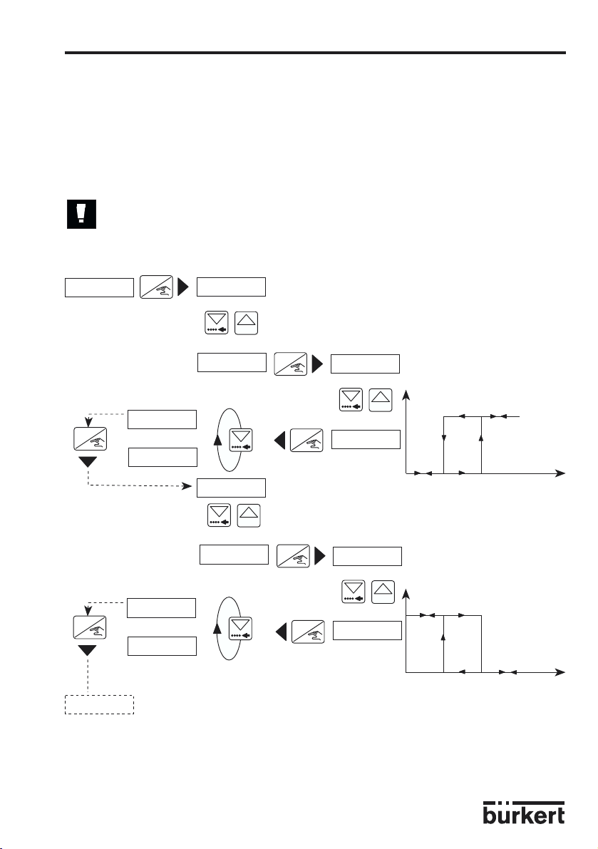
4.3.3 K-Faktor
In diesem Menü wird der K-Faktor des Fittings eingegeben . Mit dem "Teach in" , kann
aber der K-Faktor, spezifisch zu den Applikationsbedingungen, praktisch ermittelt werden.
Dazu muss der Benutzer nur eine bekannte Menge durch seine Anlage fliessen lassen.
Beispiel: Um die Menge genau bestimmen zu können, füllt der Benutzer z. B. einen
Behälter von 100 Liter. Bei der Meldung "TEACH JA" drückt er die Entertaste, um die
Messung zu starten. Die Meldung "ABF ENDE" (Abfüllen Ende) erscheint. Dann schaltet er
die Pumpe ein (oder macht ein Ventil auf). Wenn sein Behälter voll ist, schaltet er die
Pumpe ab (oder macht das Ventil zu). Ein Drücken auf die Entertaste stoppt die Messung.
Der Benutzer wird dann aufgefordert, die Menge (100 Liter) einzugeben. Nach
Bestätigung wird der berechnete K-Faktor angezeigt.
Hinweis: Es wird der zuletzt eingegebene oder bestimmte K-Faktor in Anspruch
genommen.
K.FAKTOR
STROM
STROM
ENTER
TEACH N
0......9
TEACH JA
Start der Messung
ENTER
K =00.00
0......9
ENTER
ENTER
0......9
K= 117.60
ENTER
ABF ENDE
Stop der Messung
Eingabe der gemessenen Menge. Die
Einheit ist die selbe wie für den Durchfluss
K= 79.30
Anzeige des berechneten K-Faktors
Eingabe des K-Faktors
aus den Tabellen
Eingabe des
Dezimalpunkt des KFaktors
0000.0 L
ENTERENTER
Anmerkung: Die Dezimalstelle wird durch gleichzeitigen Druck der Tasten
versetzt. Sie wird, von der blinkenden Stelle aus, stets nach rechts versetzt. Zwei
Positionen sind möglich: «0000.0» und «000.00».
0......9
0100.0 L
0......9
D-25-
Page 26
4 BEDIENUNG
8025 UNIVERSAL
4.3.4 Stromausgang
Hier wird der Durchfluss-Messbereich eingegeben, der dem Stromausgang 4...20 mA
entspricht, z. B. 0 bis 180 l/min entspricht 4...20 mA. Der Messbereichsanfang kann
grösser als das Messbereichsende sein, z. B. 0 bis 180 l/min entspricht 20...4 mA
(invertiertes Ausgangssignal).
Der Maximalwert des Ausgangsignales muss den Werten der Tafel in §5.3 entsprechen.
Es gelten die Einstellungen (Einheit und Kommastelle), die für die Durchflussanzeige
gewählt worden sind.
STROM
PULS
ENTER
4= 0000
0......9
4= 0000
Eingabe des Messbereichsanfangs
ENTER
ENTER
20= 0000
0......9
20= 0180
Eingabe des
Messbereichsendes
4.3.5 Pulsausgang
In diesem Menü wird der Pulsausgang parametriert. Es wird die Durchflussmenge die
einem Puls entsprechen soll, festgelegt. Zuerst wird die Einheit und dann der Wert
eingegeben. Beispiel: 1 Impuls entspricht 5 L.
ENTER
PULS
ENTER
PU=000.00
0......9
Eingabe der Menge
die einem Puls
entspricht
0......9
LITER
M3
USGAL
RELAIS
IMPGAL
D-26-
ENTER
PU=005.00
Page 27
4 BEDIENUNG
1-=0000
0......9
ENTER
0......9
ENTER
ENTER
ENTER
0......9
0......9
ENTER
1- (8) 1+ (10)
invertieren ja
zu
offen
Kontakt
ENTER
ENTER
1- (8) 1+ (10)
invertieren nein
Durchfluss
zu
offen
Kontakt
1
-=0008
1+=0000
1+=0010
2-=0000
2-=0040
2+=0000
2+=0044
RELAIS
INV NEIN
INV JA
INV JA
INV NEIN
FILTER
Durchfluss
8025 UNIVERSAL
4.3.6 Relais
Hier erfolgt die Parametrierung der Grenzkontakte. Für jedes Relais werden 2 Grenzwerte
eingegeben; 1- und 1+ bzw. 2- und 2+. Der Benutzer hat auch die Möglichkeit die Relais
zu invertieren. Es sind die Einheit und die Kommastelle, die im Untermenü "EINHEIT"
gewählt worden sind, aktiv.
Die maximalen Werte der Grenzwerte müssen den Werten des §5.3 entsprechen.
Die folgende Bedingung muss eingehalten werden: 1- ≤ 1+, 2- ≤ 2+.
Erhöhung des Digits
durch fortlaufendes
Digit Änderung des
ersten Grenzwertes
Drücken
D-27-
Page 28
4 BEDIENUNG
8025 UNIVERSAL
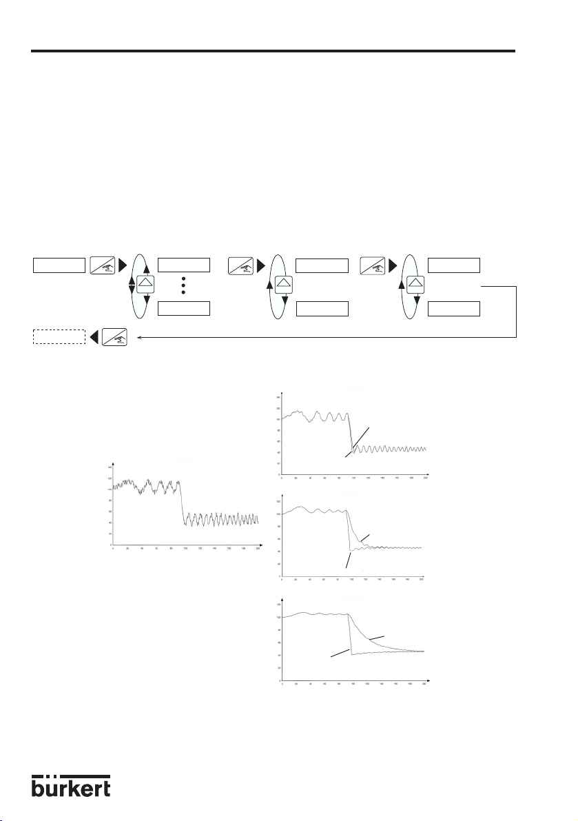
4.3.7 Filterfunktion und minimale Eingangsfrequenz
Die Filterfunktion bietet einen Messwertglättungseffekt, um Schwankungen des
Ausgangsstroms und der Anzeige zu unterdrücken. Es stehen 2 Filtertypen (schnell und
langsam) zur Verfügung. Jeder dieser Filtertypen hat 10 Stufen (von 0 bis 9, wobei 0
keinen Messwertglättungseffekt hat).
Das "schnelle" Filter wird für schnelle Änderungen bei schwankendem Durchfluss
verwendet. (Bei schneller Schließung des Ventils benötigt das Filter einige Sekunden, um
den Nullpunkt zu erreichen, das schnelle Filter dagegen reagiert sofort).
Das "langsame" Filter muss unter ungünstigen Messbedingungen verwendet werden.
FILTER
TOTAL
ENTER
ENTER
0......9
FILTER 0
FILTER 9
ENTER
LANGSAM
0......9
SCHNELL
ENTER
F=0,5 HZ
0......9
F=2,5 HZ
Aus dem folgenden Diagramm ist ersichtlich, wie die verschiedenen Filter das
Durchflussignal über die Zeit beeinflussen.
FILTER 3
langsam
FILTER 0 - Istwert
schnell
FILTER 6
langsam
schnell
FILTER 9
langsam
schnell
Die minimale Eingangsfrequenz wirkt auf die Erfassungszeit eines nullen Durchflusses:
1,2 s bei 2,5 Hz und 5,2 s bei 0,5 Hz.
Die minimale Eingangsfrequenz muss entspechend der Ausgangsfrequenz des
Messelementes ausgewählt werden.
D-28-
Page 29
4 BEDIENUNG
8025 UNIVERSAL
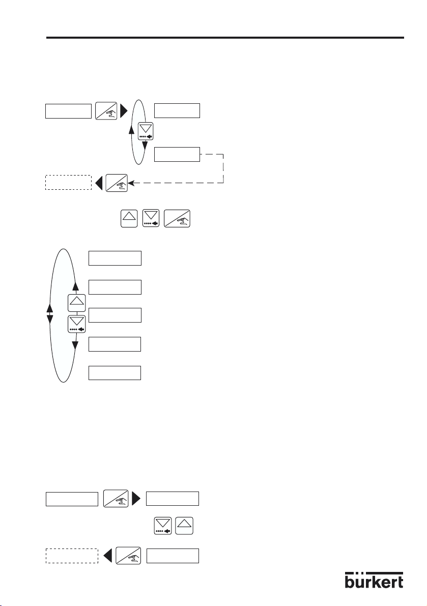
4.3.8 Totalisator
Hier werden der Haupt- und Tagestotalisator zurückgestellt. Die Rückstellung erfolgt erst
wenn die Entertaste, bei der Stelle "ENDE" im Parametriermenü, gedrückt wird.
TOTAL
ENTER
RES NEIN
RES JA
ENDE
4.4 Testmenü: gleichzeitig während 5 Sekunden
Im Testmenü werden folgende Abgleiche und Überprüfungen durchgeführt:
0......9
ENTER
0......9
OFFSET
SPAN
FREQUENZ
DURCHFLU
ENDE
ENTER
Abgleich des Nullpunktes (4 mA).
Abgleich der Spanne (20 mA).
Anzeige der Frequenz des Sensors.
Eingabe des zu simulierenden Durchflusses. Die Ausgänge
reagieren entsprechend dieser Eingabe.
Zurück ins Funktionsmenü und Abspeicherung der neuen Parameter
für OFFSET und SPAN. Ist einer der 2 Werte fehlerhaft, zeigt das
Gerät auf "OFFSET", und neue Werte, für OFFSET und SPAN, müssen
eingegeben werden.
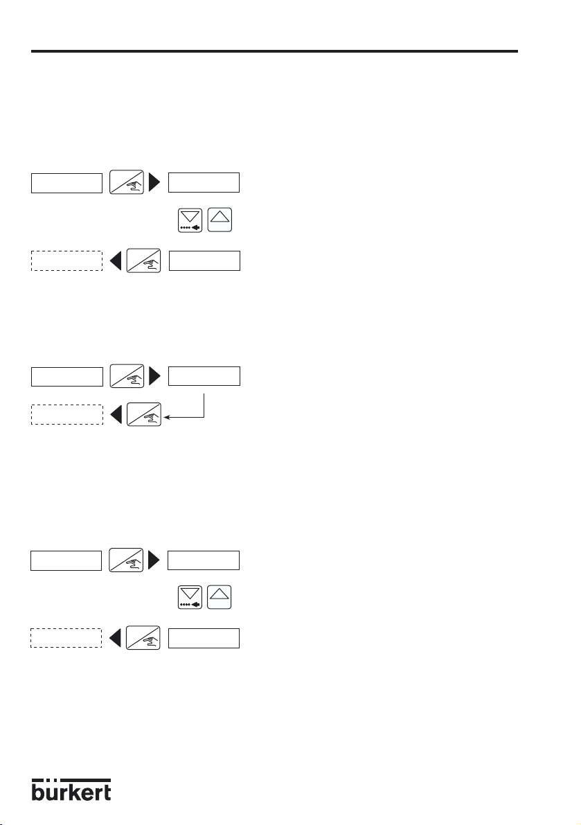
4.4.1 Offset-Abgleich
Der Kunde hat hier die Möglichkeit die Grundeinstellung der 4 mA zu korrigieren. Dazu
braucht er nur ein Strommessgerät. Wenn bei der Anzeige "OFFSET" die Entertaste
gedrückt wird, werden 4 mA vom Transmitter erzeugt. Stimmt dieser Wert nicht, kann er
korrigiert werden in dem der gemessene Wert eingegeben wird.
OFFSET
ENTER
OF
= 4.00
SPAN
ENTER
OF
0......9
= 4.02
Eingabe des gemessenen Wertes
D-29-
Page 30
4 BEDIENUNG
8025 UNIVERSAL
4.4.2 Span-Abgleich
Der Kunde hat hier die Möglichkeit die Grundeinstellung der 20 mA zu korrigieren. Der
Verlauf ist identisch zum Offset. Wenn bei der Anzeige "SPAN" die Entertaste gedrückt
wird, werden 20 mA vom Transmitter erzeugt. Stimmt dieser Wert nicht, kann er korrigiert
werden in dem der gemessene Wert eingegeben wird.
SPAN
ENTER
SP=20.00
0......9
FREQUENZ
ENTER
SP=19.90
Eingabe des gemessenen Wertes
4.4.3 Frequenzanzeige
Hier wird die Frequenz des Sensors angezeigt. Die Anzeige bleibt so lange die Entertaste
nicht gedrückt wird.
FREQUENZ
DURCHFLU
ENTER
ENTER
195.3 HZ
4.4.4 Durchfluss-Simulation
In diesem Menü kann ein Durchfluss simuliert werden. Der Benutzer hat damit die
Möglichkeit, seine ganze Anlage ohne Flüssigkeit zu prüfen. Der simulierte Wert wirkt sich
auf den Stromausgang und die Relais aus, aber nicht auf den Pulsausgang. Es sind die
Einheit und die Kommastelle, die im Untermenü "ENIHEIT" gewählt worden sind, aktiv.
DURCHFLU
ENTER
ENTER
DURCHFLU
00.00L/S
0......9
46.25L/S
Durchflusswert eingeben
Die Simulation ist aktiv, bis der Benutzer in ein anderes Untermenü geht.
D-30-
Page 31

5 WARTUNG
8025 UNIVERSAL
5.1 Hinweis Störung
Bei korrektem Einbau sind die Geräte wartungsfrei. Sollten trotzdem im Betrieb
Verunreinigungen oder Verstopfungen vorkommen, kann das Gerät (Messrad, Lager)
gereinigt werden. Dazu verwendet man im Normalfall Wasser oder ein geeignetes
Reinigungsmittel.
Wenn die Meldung "ERROR" auf der Anzeige erscheint, sind die Kalibrationsdaten verloren
gegangen. Nach Drücken der Entertaste wird das Hauptmenü erreicht, aber das Gerät
befindet sich in der Basis Einstellung (siehe § 5.2). Der Transmitter muss neu kalibriert
werden. Sollte diese Meldung öfters erscheinen, schicken Sie das Gerät zur
Niederlassung zurück.
5.2 Basis Einstellungen des 8025 bei Auslieferung
Sprache: Englisch
Einheit Durchfluss: L/s
Einheit Totalisatoren: L
Dezimalstellen: 2
K-Faktor: 100.00
Strom 4 mA: 00.00
20 mA: 00.00
Pulsausgang Einheit: L
PU: 000.10
Relais 1-: 00.00
1+: 00.00
Invert.: JA
2-: 00.00
2+: 00.00
Invert.: JA
Filter: Filter 2, schnell
Eingangfrequenz 2,5 Hz
5.3 Maximalwerte zur Einstellung des 8025 "UNIVERSAL" Transmitters
Durchfluss Strom 4...20 mA Grenzwert Relais
max Wert min. Unterschied max Wert
ml/s 1.400.000/K 100/K 1.400.000/K
ml/min 84.000.000/K 6.000/K 84.000.000/K
ml/H 5.040.000.000/K 360.000/K 5.040.000.000/K
l/s 1.400/K 0.1/K 1.400/K
l/min 84.000/K 6/K 84.000/K
l/H 5.040.000/K 360/K 5.040.000/K
m3/s 1,4/K 0,0001/K 1,4/K
m3/min 84/K 0,006/K 84/K
m3/H 5.040/K 0,36/K 5.040/K
US gal/s 1.400/K 0.1/K 1.400/K
US gal/min 84.000/K 6/K 84.000/K
US gal/H 5.040.000/K 360/K 5.040.000/K
Imp gal/s 1.400/K 0.1/K 1.400/K
Imp gal/min 84.000/K 6/K 84.000/K
Imp gal/H 5.040.000/K 360/K 5.040.000/K
D-31-
Page 32

5 WARTUNG
8025 UNIVERSAL
5.4 Ersatzteil-Stückliste
Ausführung für Schaltschrankmontage
Position Bezeichnung Bestell-Nummer
Satz mit 8 "FLOW"-Folien ohne "Relais"-Markierung 553191
Satz mit 8 "FLOW"-Folien mit "Relais"-Markierung 553192
1 Deckel aus PC , mit Fenster und Schrauben 555849
2 Elektronik-Platine ohne Relais + Schutzplatte + Montageblatt 557000
Elektronik-Platine mit Relais + Schutzplatte + Montageblatt 557001
3 Satz Montagezubehör (Schrauben, Fächerscheiben, Bolzen,
Kabelschellen) 554807
4 Dichtung 419350
Fig. 5.1
3
3
4
2
Ersatzteil-Explosionszeichnung, Ausführung für Schaltschrankmontage
D-32-
3
1
3
Page 33

5 WARTUNG
Ausführung für Feldmontage
Position Bezeichnung Bestell-Nummer
1 Komplettes Gehäuse IP65 418389
2 Versorgungsplatine 115/230 VAC 555722
3 Elektronik-Platine ohne Relais + Schutzplatte + Montageblatt 557000
Elektronik-Platine mit Relais + Schutzplatte + Montageblatt 557001
8025 UNIVERSAL
Fig. 5.2
Ersatzteil-Explosionszeichnung, Ausführung für Wandmontage
D-33-
Page 34

ANHANG
Durchfluss-Diagramm (l/min, DN in mm und m/s)
3
/h
m
5000
l/min
500
100
50
10
5
1
0.5
0.1
0.05
0.01
0.005
50000
10000
5000
1000
500
100
50
20
10
5
3
2
1
0.5
0.3
0.2
2000
1000
500
200
100
50
20
10
5
2
1
0.5
0.2
0.1
0.05
0.02
0.01
0.1 0.3 0.5 1 2 3 5 100.2
Durchflussgeschwindigkeit
l/s
Durchfluss
8025 UNIVERSAL
DN 400
DN 350
DN 300
DN 250
DN 200
DN 150
DN 125
DN 100
DN 80
DN 65
DN 50
DN 40
DN 32
DN 25
DN 20
DN 15
DN 08
DN 06
m/s
Auswahlbeispiel:
Vorgabe:
Nominaler Durchfluss: 10m3/h
Ermittlung mit idealer
Durchflussgeschwindigkeit: 2...3 m/s
Aus dem Diagramm resultiert die
erforderliche Nennweite von DN 40.
D-34-
Page 35

ANHANG
Durchfluss-Diagramm (gpm, DN in inch und fps)
8025 UNIVERSAL
gpm
20000
10000
5000
2000
1000
500
200
100
50
20
Durchfluss
10
5
2
1
0.5
0.2
0.1
0.05
16'' DN400
14'' DN350
12'' DN300
10'' DN250
8'' DN200
6'' DN150
5'' DN125
4'' DN100
3'' DN80
2 1/2'' DN65
2'' DN50
1 1/2'' DN40
1 1/4'' DN32
1'' DN25
3/4'' DN20
1/2'' DN15
1/4'' DN08
1/4'' DN06
Auswahlbeispiel:
0.02
0.01
Durchflussgeschwindigkeit
Vorgabe:
Nominaler Durchfluss: 50 gpm
Ermittlung mit idealer
Durchflussgeschwindigkeit: 8 fps
Aus dem Diagramm resultiert die
erforderliche Nennweite von 1 1/2"
D-35-
fps
30200.3 0.5 1 2 3 5 10
Page 36

8025 UNIVERSAL
D-36-
Page 37

8025 UNIVERSAL
D-37-
Page 38

8025 UNIVERSAL
D-38-
Page 39

8025 UNIVERSALTABLE OF CONTENTS
1 INTRODUCTION............................................................................................................................. E-2
1.1 Unpacking and Control ............................................................................................................................... E-2
1.2 About this Manual ........................................................................................................................................ E-2
1.3 User's Responsibility for Safety ................................................................................................................ E-2
1.4 Electromagnetic Compatibility .................................................................................................................. E-2
2 SPECIFICATION ............................................................................................................................ E-3
2.1 Transmitter Specification ........................................................................................................................... E-3
2.2 Bürkert sensors which can be connected to a 8025 Universal ...................................................... E-3
2.3 Design and Measuring Principle .............................................................................................................. E-4
2.4 Dimensions..................................................................................................................................................... E-5
2.5 Technical Data .............................................................................................................................................. E-6
3 INSTALLATION .............................................................................................................................. E-8
3.1 Mounting ......................................................................................................................................................... E-8
3.2 Electrical Connection ............................................................................................................................... E-10
3.2.1 Electrical connection recommendations (all versions)................................................... E-10
3.2.2 How to use the cable clips .................................................................................................... E-12
3.2.3 Using switch "SENSOR SUPPLY"...................................................................................... E-12
3.2.4 Using switches "FLOW SENSOR" and "SENSOR INPUT LOAD" ........................... E-12
3.2.5 Electrical wiring, panel-mounted version, 13-30 VDC, without relay ........................ E-14
3.2.6 Electrical wiring, panel-mounted version, 13-30 VDC, with relays ............................ E-16
3.2.7 Connecting the remote flow sensor.................................................................................... E-17
3.2.8 Allocation of the cable glands of a wall-mounted version............................................. E-17
3.2.9 Electrical wiring, wall-mounted version, 13-30 VDC, with or without relay ............. E-18
3.2.10 Electrical wiring, wall-mounted version, 115/230 VAC, without relay ...................... E-19
3.2.11 Electrical wiring, wall-mounted version, 115/230 VAC, with relays .......................... E-20
4 OPERATION .................................................................................................................................. E-21
4.1 Transmitter Operating and Control Elements .................................................................................... E-21
4.2 Operation Mode Display ......................................................................................................................... E-22
4.3 Calibration Mode Display ........................................................................................................................ E-22
4.3.1 Languages.................................................................................................................................. E-23
4.3.2 Engineering Units ..................................................................................................................... E-23
4.3.3 K-Factor ...................................................................................................................................... E-24
4.3.4 Output Current.......................................................................................................................... E-24
4.3.5 Pulse Output.............................................................................................................................. E-25
4.3.6 Relay ............................................................................................................................................ E-26
4.3.7 Filter Function and min. input frequency............................................................................ E-27
4.3.8 Totalizer ....................................................................................................................................... E-28
4.4 Test Menu .................................................................................................................................................... E-28
4.4.1 Offset-Compensation ............................................................................................................. E-28
4.4.2 Span-Compensation ............................................................................................................... E-29
4.4.3 Frequency Display.................................................................................................................... E-29
4.4.4 Flow Simulation......................................................................................................................... E-29
5 MAINTENANCE ............................................................................................................................ E-30
5.1 Trouble-shooting ....................................................................................................................................... E-30
5.2 Factory Settings of 8025 "UNIVERSAL" transmitter ....................................................................... E-30
5.3 Limit values for 8025 "UNIVERSAL" setting...................................................................................... E-30
5.4 Spare Parts List ......................................................................................................................................... E-31
APPENDIX .......................................................................................................................................... E-33
Flow charts ............................................................................................................................................................................ E-33
EC Conformity...................................................................................................................................................................... F-37
E-1-
Page 40

Dear Customer,
8025 UNIVERSAL1 INTRODUCTION
BEFORE INSTALLING OR USING THIS
PRODUCT, PLEASE TAKE OUR
ADVICE AND READ THE ENTIRE
MANUAL THOROUGHLY.
This will enable you to fully profit from all of
the advantages offered by this product.
1.1 Unpacking and Control
Please verify that the product is complete
and free from any damage.
Compare the Type specifications on the
label to the adjacent list to ensure that you
have received the proper unit. If there is
any loss or damage, please contact your
local Bürkert subsidiary.
1.2 About this Manual
This manual does not contain any warranty
statement. Please refer to our general
terms of sale and delivery.
Only properly-trained staff should install
and/or repair this product. If difficulties
should occur at the time of installation,
please contact your nearest Bürkert sales
office for assistance.
1.3 User's Responsibility for Safety
Bürkert manufactures a broad range of flow
transmitters. While each of these products
is designed to operate in a wide variety of
applications, it is the user's responsibility to
select a transmitter model that is
appropriate for the application, install it
properly, and maintain all components.
Special attention must be paid to the
chemical resistance of the transmitter
against the fluids which are directly
contacting the product.
This symbol appears in the
manual to call special attention
to instructions that affect the
safe installation, function and
use of the product.
1.4 Electromagnetic compatibility
This device fulfills the essential
requirements of te directives 2004/108/EC
(EMC) and 73/23/EC (DBT).
In order to comply with the directives, the
wiring instructions must be followed.
The device has been tested according to
the following EMC standards:
- EN 61000-6-3
- EN 61000-6-2
- EN 61010-1
E-2-
Page 41

8025 UNIVERSAL2 SPECIFICATION
2.1 Transmitter designation
Transmitter 8025 "UNIVERSAL" Panel version
Designation Power supply Order code
4-20 mA, 2 relays, pulse output, 2 totalizers 13-30 VDC 419537
4-20 mA, pulse output, 2 totalizers 13-30 VDC 419538
Transmitter flow 8025 "UNIVERSAL" Wall-mounted version
Designation Power supply. Order code
4-20 mA, 2 relays, pulse output, 2 totalizers 13-30 VDC 419540
4-20 mA, pulse output, 2 totalizers 13-30 VDC 419541
4-20 mA, 2 relays, pulse output, 2 totalizers 230 VAC 419543
4-20 mA, pulse output, 2 totalizers 230 VAC 419544
2.2 Burkert Sensors which can be connected to a 8025 Universal
The Flow sensor is not supplied with the transmitter 8025 "UNIVERSAL"; It has to be
ordered separately.
The following Burkert flow sensors with a frequency output can be connected to a 8025
Universal transmitter:
- 8030 standard, 8020 (PVDF paddle-wheel with integrated magnets)
- 8030 HT (stainless steel paddle-wheel)
- 8041 (Inductive) (except 8025 Universal ref. 419543)
- 8039 (Optical)
- 8071 (oval gear)
- 8031 (turbine)
Please note:
- the type of output, the supply voltage and the input load of the sensor to correctly
position the switches of the transmitter 8025 (see § 3.23 and 3.2.4)
- the K factor of the sensor (depends on the pipe diameter) to calibrate the transmitter
8025 (see § 4.3.3).
E-3-
Page 42

8025 UNIVERSAL2 SPECIFICATION
2.3 Design and Measuring Principle
Design
The panel version consists of an electronic board integrated in a front-cover.
The output signals are available on terminal strips on the electronic board.
The wall-mount version consists of a transducer with display in a splash-proof plastic IP65
enclosure.
The output signals are provided on a terminal strip inside the electronical enclosure via 3
cable glands
Measuring Principle
The sensor produces pulses, which frequency is proportional to the flow.
The transducer has a measuring range of 0.5 or 2.5 to 1400 Hz corresponding to a flow
range from 0.005 ml/s or 0.025 ml/s to 12884 l/s.
A 4-20 mA standard output signal proportional to the flow is available.
The transducer requires a power supply of 13-30 VDC.
The thresholds values of the transducer with two additional relays are freely adjustable.
OPTION: The flow transmitter in wall-mount version can be fitted with a 115/230 VAC
power supply.
E-4-
Page 43

2 SPECIFICATION
2.4 Dimensions
Panel-mounted version + drilling jig
88
76
8025 UNIVERSAL
38
25
95
80
76
50
88
Wall-mounted version
23
23
90
31.50
95
80
76
50
126
covering strip
covering strip
120
143
Fig. 2.1
Cable-glands
Dimensions of flow transmitter 8025 Universal
E-5-
Page 44

2 SPECIFICATION
8025 UNIVERSAL
2.5 Technical data
Environment
Ambient temperature 0 to 60 °C (use and storage)
Relative humidity max 80 %, non condensated
Protection rating IP65 (wall-mounted and front side of panel-mounted version)
IP20 (rear side of panel-mounted version)
Materials
Housing PC (panel-mounted) - ABS (wall-mounted)
Cover PC
Front foil Polyester
Screws Stainless steel
Cable glands PA
Cable clip PA
Electrical features
Power supply 13-30 VDC (L+) ± 10%, filtered and regulated, or
Polarity reversal protected
Current consumption (Without consumption of pulse output and sensor
Output current 4...20 mA, sourcing or sinking mode connection
Pulse output polarized, potential free, 5 - 30 VDC, 100 mA,
Relay output 2 relays, 3 A, 230 VAC, programmable
Electrical wiring Through shielded cable, 1.5 mm
115/230 VAC - 50/60 Hz (see technical specifications
115/230 VAC, below)
supply):
≤ 70 mA version with relays
≤ 20 mA version without relay
Loop impedance max:
1200 Ω at 30 VDC; 900 Ω at 24 VDC;
450 Ω at 15 VDC; 300 Ω at 13 VDC;
1000 Ω when supplied with 115/230 VAC
protected. Line drop at 100 mA: 1.5 VDC
2
50 m max. length (P. supply, current and pulse outputs)
max. cross-section 1.5 mm2 (relay)
max. cross-section,
E-6-
Page 45

2 SPECIFICATION
Sensor connection
8025 UNIVERSAL
Signal Frequency: 0.5 to 1400 Hz or 2.5 to 1400 Hz,
Input impedance depending on selection made with switch
Power supply depending on selection made with switch "SENSOR
Technical specifications 115/230 VAC
Voltage supplied 27 VDC regulated
Max. current 250 mA
Integrated protection fuse 250 mA temporised
Power 6 VA
adjustable;
Max. voltage: 30 VDC
Pulse type: open collector (NPN or PNP), TTL ...
Sinus type (coil): sensitivity of 80 mV peak-peak
typical at 250 Hz
"SENSOR INPUT LOAD" (see § 3.2.4)
SUPPLY":
5 VDC, max. 100 mA (Position 1)
12 VDC, max. 100 MA (Position 2)
11-28 VDC (L+ - 2 VDC), max. 100 mA
E-7-
Page 46

8025 UNIVERSAL3 INSTALLATION
3.1 Mounting
Installation Guidelines
The device must be protected from the rain, constant heat radiation and
other environmental influences such as magnetic fields or direct
exposure to sunlight.
3.1.1 Panel-mounted version (fig. 3.1)
Respect the installation specifications described in the instruction manual of the remote
sensor.
Follow the instructions below to install the transmitter:
1. Use the supplied drilling jig to cut away the necessary opening in the panel. Make sure
to scrupulously respect the dimensions indicated.
2. Place the gasket on the 4 screws of the cover.
Note: Use the 4 M4x25 screws supplied if the panel door is too thick.
3. Place the cover+gasket set on the cut-away with the electronic board facing the inside
of the panel.
4. Insert the 4 washers onto the 4 screws and fit the device to the panel using the 4 nuts.
5. Connect according to instructions described in chapter 3.2.
6. Use the supplied 4 cable clips to fit the cables to the protective plate.
Screw
Cable clip
Fig. 3.1
Washer
Nut
Gasket
Mounting 8025 Universal, panel-mounted version
E-8-
Page 47

3 INSTALLATION
8025 UNIVERSAL
3.1.2 Wall-mounted version (fig. 3.2)
Respect the installation specifications described in the instruction manual of the remote
sensor.
The transmitter in wall-mounted version is equipped with 4 fixing holes in the bottom
enclosure. Remove the white blanking stripes and the cover to access to fixing holes .
The electrical wiring is described in section 3.2.
Fig. 3.2
Switch for power supply
selection 115/230 V AC
5678910
SOURCE SINK
CURRENT
SENSOR SUPPLY
Iout L+ L-
FLOW SENSOR
1
+5V
2
+12V
3
L+
13..30Vdc
1
2
3
4
PE
Supply
NC
NC
COIL
PE
PULSE INPUT
SUPPLY
-
+
NC
NPN/PNP
REL2
3A/230VAC
P- P+
OUTPUT
Fuse
PE PE
SENSOR
PULSE
INPUT LOAD
123
39K
470 2.2K
COIL
NPN
PNP
NPN
COIL
PNP
FLOW SENSOR
REL1
Mounting 8025 Universal, wall-mounted version
T 250 mA
LN
LN
230V
230V
230V
E-9-
Page 48

8025 UNIVERSAL3 INSTALLATION
3.2 Electrical Connection
3.2.1 Electrical connection recommendations (all versions)
● Do not open and wire the device with the power supply connected.
● The electrical installation of the building where the transmitter is
installed must be secured by a switch or a circuit breaker.
It should be installed near the transmitter, be easily accessible and be
clearly identified as the switchgear of the transmitter.
● It is recommended to put security devices on :
Power supply: Fuse (300 mA - temporised) and an interrupter
Relay: 3A max. fuse and circuit breaker (depending on application).
● Do not apply in the same cable both a dangerous voltage and a very
low safety voltage to the relays.
● Use shielded cables with a temperature limit of 80°C minimum.
● For normal operating conditions the measuring signal can be transmitted by a
shielded cable of 0.75 mm2 cross section.
● The line must not be installed in combination with carrying lines with a higher
voltage or frequency.
● If a combined installation cannot be avoided, a minimum space of 30 cm should be
respected.
● The cable diameter must be between 6 and 12 mm;
If 2 cables are needed, use the supplied multiway seal and 4-mm diameter cables.
● The 13-30 VDC power supply must be filtered and regulated.
● Ensure the equipotentiality of the installation (power supply - transmitter - medium):
- The various earth spots in the installation have to be connected together to
eliminate the potential differences that may occur between different earthes.
- Observe faultless grounding of the cable shielding.
- Earth the negative terminal of the power supply to suppress the common mode
currents. If direct earthing is not possible insert a 100 nF / 50 V-capacitor
between the negative terminal and the earth.
Special attention has to be paid if the device is installed on plastic pipes because
there is no direct earthing possible.
Proper earthing is performed by earthing together the metallic devices such as pumps
or valves, that are as close as possible to the transmitter.
E-10-
Page 49

3 INSTALLATION
Equipotentiality skeleton diagram
8025 UNIVERSAL
Power sypply
Power supply
+
-
(*)
+
-
(*)
Metallic devices
(valve, pump,...)
8025
Panel- or wallmounted version
8030
Metallic pipes
8025
Panel- or wallmounted version
8020
Plastic pipes
(*) If direct earthing is impossible, connect a 100 nF/50 V capacitor between the negative terminal and the earth.
E-11-
Page 50

3.2.2 How to use the cable clips
8025 UNIVERSAL3 INSTALLATION
Before wiring the device, insert the
supplied cable clips into the cuts of the
electronic board and, if fitted, into the cut
of the 115/230 VAC power supply board.
Fig. 3.3
Using the cable clips
3.2.3 Using switch "SENSOR SUPPLY"
Before connecting the remote sensor to the 8025 Universal, make sure that switch
"SENSOR SUPPLY" on the electronic board of the 8025 Universal is correctly positioned.
Switch Voltage supplied
SENSOR SUPPLY to the remote sensor
FLOW SENSOR
SENSOR SUPPLY
1
+5V
2
3
+12V
L+
Position 1 +5 VDC
Position 2 +12 VDC
Position 3 - either +27 VDC (if the 8025 Universal
is powered by a 115/230 VAC supply)
- or = supply voltage of the 8025
Universal (if the 8025 Universal
is powered by a 13-30 VDC supply)
3.2.4 Using switches "FLOW SENSOR" and "SENSOR INPUT LOAD"
Before connecting the remote sensor to the 8025 Universal, make sure that switch
"FLOW SENSOR" to select the type of sensor connected and switch "SENSOR INPUT
LOAD" to select the type of sensor output, on the electronic board of the 8025 Universal,
are correctly positioned.
E-12-
Page 51

8025 UNIVERSAL3 INSTALLATION
Output signal Connecting remote sensor to
of remote sensor the 8025 Universal
UPPLY
Pulse, NPN NPN/PNP - Position 1 (for a
SENSOR
Sinus (coil) COIL Position 3
SENSOR
Supply
13..30Vdc
1
PULSE INPUT
2
NC
3
NC
NC
4
PE
FLOW SENSOR
COIL
L2
Terminals
"FLOW SENSOR"
3
1
2
PE
8025 UNIVERSAL
Terminals
"FLOW SENSOR"
1
2
PE
8025 UNIVERSAL
SUPPLY
-
+
NPN/PNP
R
39 kΩ
+5 V
2
COIL
470 2.2
PNP
NPN
COIL NPN/PNP
FLOW SENSOR
SENSOR INPUT
LOAD
3
39K
COIL
470 2.2K
PNP
load resistance
R = 2,2 kΩ)
- Position 2 (for a
load resistance
R = 470 Ω)
(input impedance
of 39 kΩ)
2
NPN
1
Pulse, PNP NPN/PNP Position 3
Terminals
"FLOW SENSOR"
3
39 kΩ
(input impedance
of 39 kΩ)
1
2
PE
SENSOR
On/Off contact NPN/PNP - Position 1 (for a
(Reed relay, load resistance
for example) R = 2,2 kΩ)
SENSOR
0-5 VDC NPN/PNP Position 3
standard signal (input impedance
(TTL, for example) of 39 kΩ)
8025 UNIVERSAL
"FLOW SENSOR"
...
8025 UNIVERSAL
"FLOW SENSOR"
Terminals
3
1
2
PE
Terminals
3
1
R
39 kΩ
+5 V
- Position 2 (for a
load resistance
R = 470 Ω)
2
PE
SENSOR
8025 UNIVERSAL
E-13-
Page 52

8025 UNIVERSAL3 INSTALLATION
3.2.5 Electrical wiring, panel-mounted version, 13-30 VDC, without relay
Before wiring the device, please read § 3.2.1, 3.2.2, 3.2.3, 3.2.4 and 3.2.7
carefully.
Install the transmitter as described in § 3.1.1. Connect the terminals according to the pin
assignment described below.
- Only manipulate the switches when the device is not powered.
- Make sure switches "SENSOR SUPPLY", "FLOW SENSOR" and
"SENSOR INPUT LOAD" are correctly positioned according to the
separate sensor version (see § 3.2.3 and 3.2.4).
L+ (13-30 VDC)
4-20 mA output
Switch [1] :
see below
Remote flow sensor
connection:
see § 3.2.7
Switch "Voltage supplied to
the remote sensor":
see § 3.2.3
SOURCE SINK
CURRENT
Iout
L- (0V)
Pulse output 팫
Pulse output 팬
Connect the shielding of the power supply and
pulse output cables
SOURCE SINK
CURRENT
SENSOR SUPPLY
Iout L+ L-
FLOW SENSOR
1
+5V
2
+12V
3
L+
Supply
13..30Vdc
1
2
3
4
PE
PULSE INPUT
-
NC
+
NC
NC
COIL
REL2
PE
SUPPLY
NPN/PNP
3A/230VAC
P- P+
PULSE
OUTPUT
PE PE
REL1
COIL
FLOW SENSOR
39K
COIL
PNP
SENSOR
INPUT LOAD
470
Switch "Load impedance of
remote sensor": see § 3.2.4
123
2.2K
NPN
NPN
PNP
Switch "Type of remote sensor":
see § 3.2.4
Switch [1], "Current output connection mode":
- Set to "SOURCE" position if 4-20 mA output is connected to a PLC in sourcing
mode
- Set to "SINK" position if 4-20 mA output is connected to a PLC in sinking mode
Fig. 3.4
Wiring the 8025 Universal, panel-mounted version, 13-30 VDC, without relay
E-14-
Page 53

8025 UNIVERSAL3 INSTALLATION
Connecting the 8025 Universal, panel-mounted version, 13-30 VDC, to a PLC
The 4-20 mA and pulse outputs of the transmitter with a 13-30 VDC supply, can be
connected to a PLC. Depending on the PLC type and the connection mode of the current
output, set switch [1] to position "SOURCE" (sourcing mode) or "SINK" (sinking mode)
(see fig. below and 3.4).
Connection of the 8025 current
output in sourcing mode
4-20 mA
Switch [1]
(see fig. 3.4)
SOURCE SINK
CURRENT
300 mA
+
-
Iout
Iout L+ L-
Supply
13..30Vdc
PE
P- P+
PULSE
OUTPUT
+
-
13-30 VDC
(*)
PE PE
SENSOR
INPUT LOAD
Connection of the 8025 pulse output
(wired in NPN mode)
13-30 VDC
P. Supply
300 mA
+
-
(*)
+
5-30 VDC
-
+
-
Connection of the 8025 current
output in sinking mode
4-20 mA
Switch [1]
(see fig. 3.4)
SOURCE SINK
CURRENT
300 mA
+
-
Iout
Iout L+ L-
Supply
13..30Vdc
PE
P- P+
PULSE
OUTPUT
+
-
13-30 VDC
PE PE
Connection of the 8025 pulse output
(wired in PNP mode)
+
5-30 VDC
-
+
-
PLC
13-30 VDC
P. Supply
300 mA
+
-
(*)
(*)
SENSOR
INPUT LOAD
PLC
SOURCE SINK
CURRENT
Iout L+ L-
13..30Vdc
SOURCE SINK
PE PE
P- P+
PE
Supply
PULSE
OUTPUT
P-
8025:
NPN
SENSOR
INPUT LOAD
P+
CURRENT
Iout L+ L-
13..30Vdc
Supply
PE PE
P- P+
PE
PULSE
OUTPUT
P-
8025:
PNP
SENSOR
INPUT LOAD
P+
(*) If direct earthing is impossible, connect a 100 nF/50 V capacitor between the negative terminal and the earth.
Fig. 3.5
Wiring the 8025 Universal, 13-30 VDC, to a PLC
E-15-
Page 54

3 INSTALLATION
8025 UNIVERSAL
3.2.6 Electrical wiring, panel-mounted version, 13-30 VDC, with relays
Before wiring the device, please read § 3.2.1, 3.2.2, 3.2.3, 3.2.4 and 3.2.7
carefully.
Install the transmitter as described in § 3.1.1. Connect the terminals according to the pin
assignment described below.
- Only manipulate the switches when the device is not powered.
- Make sure switches "SENSOR SUPPLY", "FLOW SENSOR" and
"SENSOR INPUT LOAD" are correctly positioned according to the
separate sensor version (see § 3.2.3 and 3.2.4).
L+ (13-30 VDC)
L- (0V)
4-20 mA output
Pulse output 팫
Pulse output 팬
Connect the shielding of the power supply and
pulse output cables e
Switch [1]:
(see fig. 3.4)
Remote flow sensor
connection: see § 3.2.7
Switch "Voltage supplied
to the remote sensor":
see § 3.2.3
SENSOR SUPPLY
+
-
SOURCE SINK
CURRENT
FLOW SENSOR
1
+5V
2
+12V
3
L+
Iout L+ L-
Supply
13..30Vdc
1
2
3
4
PE
PULSE INPUT
SUPPLY
-
NC
+
NC
NC
COIL
NPN/PNP
REL2
3A/230VAC
PE PE
REL1
COIL
FLOW SENSOR
39K
COIL
PNP
SENSOR
INPUT LOAD
470
NPN
P- P+
PE
PULSE
OUTPUT
+
Switch "Load impedance of
remote sensor": see § 3.2.4
123
2.2K
NPN
PNP
Switch "Type of remote sensor":
see § 3.2.4
Connection of relay 1 to the
-
Type 142
Connection of relay 2 to the
Type 121
Relay cables must be fitted here to the board using the
supplied cable clips (see § 3.2.2)
Fig. 3.6
Wiring the 8025 Universal, panel-mounted version, 13-30 VDC, and connection
examples for the relays
Connecting the 8025 Universal, panel-mounted version, 13-30 VDC, to a PLC
The 4-20 mA and pulse outputs of the transmitter with a 13-30 VDC supply and relays
can be connected to a PLC in the same way as the panel-mounted version without relay
(see Fig. 3.5, § 3.2.5).
E-16-
Page 55

3 INSTALLATION
8025 UNIVERSAL
3.2.7 Connecting the remote flow sensor
Connect the remote flow sensor to the "FLOW SENSOR" terminal strip of the electronic
board, by respecting the pin assignment according to the output type of the remote
sensor, either sinus output or pulse output. First of all, correctly configure the "SENSOR
SUPPLY" switch (see § 3.2.3) and the "FLOW SENSOR" switch (see § 3.2.4).
Pulse
L+5 VDC, +12 VDC or L+
(depending on switch
NC
"SENSOR SUPPLY")
Shielding of the sensor cable
FLOW SENSOR
1
2
{
3
NC
4
PE
Shielding of the sensor cable
FLOW SENSOR
1
2
3
4
PE
Sensor with a sinus output Sensor with a pulse ouput
NC = Not connected
3.2.8 Allocation of the cable glands of the wall-mounted versions
Pass the cables through the cable glands by preferably respecting the following allocation
in order to ease the wiring:
Output cables
Flow sensor cable
13-30 VDC or
115/230 VAC
supply cable
Fig. 3.7
Allocation of the cable glands, wall-mounted versions
E-17-
Page 56

3 INSTALLATION
8025 UNIVERSAL
3.2.9 Electrical wiring, wall-mounted, 13-30 VDC, with or without relay
Before wiring the device, please read § 3.2.1, 3.2.2, 3.2.3, 3.2.4 and 3.2.7
carefully.
Install the device as described in § 3.1.2. Unscrew the 4 screws of the cover and unscrew
the cable glands. Pass the cables through the cable glands by preferably respecting the
allocation indicated in § 3.2.8.
Connect the terminals according to the pin assignment described below.
- Only manipulate the switches when the device is not powered.
- Make sure switches "SENSOR SUPPLY", "FLOW SENSOR" and
"SENSOR INPUT LOAD" are correctly positioned according to the
separate sensor version (see § 3.2.3 and 3.2.4).
Pulse output 팫
P- P+
PE
OUTPUT
Pulse output 팬
PE PE
PULSE
COIL
REL1
Connect the shielding of the power supply and pulse
output cables
Switch "Load impedance of
SENSOR
INPUT LOAD
39K
470
COIL
PNP
NPN
FLOW SENSOR
123
2.2K
NPN
PNP
remote sensor": see § 3.2.4
Switch "Type of remote
sensor": see § 3.2.4
4-20 mA output
Switch [1]:
(see fig. 3.4)
Remote flow sensor
connection: see
§ 3.2.7
L- (0V)
L+ (13-30 VDC)
SOURCE SINK
CURRENT
FLOW SENSOR
SENSOR SUPPLY
1
+5V
2
+12V
3
L+
Iout L+ L-
Supply
13..30Vdc
1
2
3
4
PE
PULSE INPUT
-
NC
+
NC
NC
COIL
NPN/PNP
REL2
SUPPLY
3A/230VAC
Switch "Voltage
supplied to the
remote sensor":
see § 3.2.3
Connection of the relays
(depending on version, see ex. Fig 3.6)
Relay cables must be fitted here to the board using
the supplied cable clips (see § 3.2.2)
Fig. 3.8
Wiring 8025 Universal, wall-mounted version, 13-30 VDC
Connection of transmitter 8025, wall-mounted, 13-30 VDC, to a PLC
The 4-20 mA and pulse outputs of the transmitter in a wall-mounted version, with a 13-30
VDC supply, can be connected to a PLC in the same way as the panel-mounted version
without relay (see Fig. 3.5, § 3.2.5).
E-18-
Page 57

3 INSTALLATION
8025 UNIVERSAL
3.2.10 Electrical wiring, wall-mounted, 115/230 VAC, without relay
Before wiring the device, please read § 3.2.1, 3.2.2, 3.2.3, 3.2.4 and 3.2.7
carefully.
Install the device as described in § 3.1.2. Unscrew the 4 screws of the cover and unscrew
the cable glands. Pass the cables through the cable glands by preferably respecting the
allocation indicated in § 3.2.8.
Connect the terminals according to the pin assignment described below.
- Only manipulate the switches when the device is not powered.
- Make sure switches "SENSOR SUPPLY", "FLOW SENSOR" and
"SENSOR INPUT LOAD" are correctly positioned according to the
separate sensor version (see § 3.2.3 and 3.2.4).
White wire * P+
Brown wire * P-
Black wire * L-
Red wire * L+
Green wire * 4-20 mA
Switch [1]:
(see fig. 3.4)
Remote flow
sensor
connection:
see § 3.2.7
SENSOR SUPPLY
SOURCE SINK
CURRENT
FLOW SENSOR
1
+5V
2
3
Iout L+ L-
Supply
13..30Vdc
1
PULSE INPUT
2
-
NC
3
+
NC
NC
4
PE
COIL
REL2
+12V
L+
P- P+
PE
SUPPLY
NPN/PNP
3A/230VAC
PULSE
OUTPUT
PE PE
Loop through shield*
SENSOR
INPUT LOAD
123
39K
2.2K
470
COIL
PNP
NPN
NPN
COIL
PNP
FLOW SENSOR
REL1
Fuse
T 250 mA
5678910
115 VAC / 230 VAC
switch
230V
230V
230V
LN
LN
{
* Factory prewired
Fig. 3.9
Wiring 8025 Universal, wall-mounted version, 115/230 VAC, without relay
All the cables must be
fitted here
To connect the current output to a
PLC: see § 3.2.11, Fig. 3.10
Connect the shielding
of the output cables
+
-
+
Connecting the pulse output
to a PLC, NPN mode
E-19-
5-30 VDC
-
Iout
L+
L-
Connection of the
115/230 VAC
power supply
P+
P-
P+
P-
+
5-30 VDC
-
+
-
Connecting the pulse
output to a PLC, PNP mode
Page 58

3 INSTALLATION
8025 UNIVERSAL
3.2.11 Electrical wiring, wall-mounted, 115/230 VAC, with relays
Before wiring the device, please read § 3.2.1, 3.2.2, 3.2.3, 3.2.4 and 3.2.7
carefully.
Install the device as described in § 3.1.2. Unscrew the 4 screws of the cover and unscrew
the cable glands. Pass the cables through the cable glands by preferably respecting the
allocation indicated in § 3.2.8.
Connect the terminals according to the pin assignment described below.
- Only manipulate the switches when the device is not powered.
- Make sure switches "SENSOR SUPPLY", "FLOW SENSOR" and
"SENSOR INPUT LOAD" are correctly positioned according to the
separate sensor version (see § 3.2.3 and 3.2.4).
White wire * P+
Brown wire * P-
Black wire * L-
Red wire * L+
Green wire * 4-20 mA
Switch [1]:
(see fig. 3.4)
Remote flow
sensor
connection:
see § 3.2.7
SENSOR SUPPLY
SOURCE SINK
CURRENT
FLOW SENSOR
1
+5V
2
+12V
3
L+
Iout L+ L-
Supply
13..30Vdc
1
2
3
4
PE
PULSE INPUT
-
NC
+
NC
NC
COIL
REL2
PE
SUPPLY
NPN/PNP
3A/230VAC
P- P+
PULSE
OUTPUT
Loop through shield*
PE PE
SENSOR
INPUT LOAD
123
39K
2.2K
470
COIL
PNP
NPN
NPN
COIL
PNP
FLOW SENSOR
REL1
Fuse
T 250 mA
5678910
115 VAC / 230 VAC
switch
230V
230V
230V
LN
LN
{
{
* Factory prewired
{
All the cables must be
fitted here
Relay cables must be fitted here to the board
using the supplied cable clips (see § 3.2.2)
Iout
Iout
Iout
4-20 mA
Connecting the current
output in sourcing mode
L-
-
+
Connecting the current
output in sinking mode
Fig. 3.9
L+
-
+
4-20 mA
Wiring 8025 Universal, wall-mounted version, 115/230 VAC, without relay
E-20-
Connect the shielding
of the output cables
Connection of the
115/230 VAC
power supply
P-
To connect the pulse
output to a PLC:
see § 3.2.10 Fig. 3.9
P+
Page 59

8025 UNIVERSAL4 OPERATION
The operation of the 8025 is classified according to three levels.
A) Display
This menu displays flow, output current, main totalizer and daily totalizer. The daily totalizer
can also be reset in this menu.
B) Parameter Definition
All the necessary settings, such as the language, engineering units, K-factor, 4-20 mA
measuring range, pulse output, relay and filter are carried through in this menu.
Here, the main, as well as the daily totalizer are simultaneously reset.
C) Testing
A flow can be simulated in this menu, which allows to test a process in the "dry-run
condition".
This menu also displays the sensor frequency and allows to change the basic settings
(Offset, Span) of the device.
4.1 Transmitter Operating and Control Elements
To scroll-up the menus
or increase a value
To scroll-down the menus or
select a digit to be modified
Relay 1 status
E-21-
Validate chosen
parameter or menu
Relay 2 status
Page 60

4 OPERATION
.
4.2 Operation Mode Display
The following variables are displayed in the operation mode:
8025 UNIVERSAL
45,6 L/m
16,45
0......9
80529 L
6247 L
4.3 Calibration Mode
Press simultaneously for 5 seconds
The following variables can be set in the parameter definition menu:
ENTER
LANGUAGE
K-FAKTOR
CURRENT
Flow rate in the required engineering unit (see calibration menu).
4-20 mA output signal, proportional to the flow
mA
according to the selected measuring range
Main totalizer in the required engineering unit (see calibration
menu). Reset in the calibration menu.
Daily totalizer in the same engineering unit as the main totalizer.
A point behind the unit differentiates it from the main totalizer.
Reset by simultaneously pressing the keys for 2
seconds.
Language selection between English, German, French and
Italian.
Selection of engineering units to display flow rate and totalizer.
UNIT
Input of K-factor according to chart or Teach-in function in order
to determine the specific K-factor.
Setting of the 4-20 mA measuring range.
0......9
0......9
PULSE
RELAY
FILTER
TOTAL
END
Parameter definition of pulse output (unit and quantity).
Parameter definition of relays. This message only appears if the
relay option has been installed.
Dampening selection. There are ten different steps and 2
filtering modes available.
Selection of the min. input frequency.
Totalizer resetting.
Return to operation mode and storage of new parameters.
E-22-
Page 61

4.3.1 Language
ENTER
LANGUAGE
0......9
ENGLISH
DEUTSCH
FRANCAIS
8025 UNIVERSAL4 OPERATION
The required language is
confirmed and activated via the
Enter-key.
UNIT
ENTER
4.3.2 Engineering Units
UNIT
ENTER
FLOW
0......9
TOTAL
ITALIANO
ENTER
ENTER
m LIT/SEC
m
LIT/MIN
m
LIT/H
LIT/SEC
LIT/MIN
0......9
LIT/H
M3/MIN
M3/H
US GAL/S
US GAL/M
US GAL/H
IMP GA/S
IMP GA/M
IMP GAL/H
If metric units
m
LITER
0...9
LITER
The flow can be
displayed in any
engineering unit with 0,
1, 2 or 3 decimal digits.
ENTER
DEC PT 0
DEC PT 1
0......9
DEC PT 2
DEC PT 3
ENTER
M3
K-FACTOR
K-FACTOR
Note: Return to the main menu via the sub-menu "TOTAL".
The "TOTAL" menu is only activated for metric units. Choose of US (or IMP) flow units
enforces US (or IMP) units for volume measurements.
ENTER
If US/IMP units
E-23-
Page 62

4 OPERATION
8025 UNIVERSAL
4.3.3 K-Factor
Enter the K-factor of the fitting in this menu (min 0.01 ... max 80000). The "Teach in"
function allows to practically detemine the application specific K-factor. The user only
needs to run a known quantity of liquid through the system.
Example: In order to determine a quantity as accurately as possible, fill a tank of 100
litres. When the message "TEACH YES" appears, press the Enter key to start the measuring
procedure. The message "FILL END" (end of filling) will appear. Then switch on a pump or
open a valve. As soon as the tank is full, switch off the pump or close the valve. Pressing
Enter stops the measurement. Finally enter the measured volume (100 liters). The
calculated K-factor is displayed after validation.
Note: The transmitter uses the last entered or determined K-Factor.
K.FACTOR
CURRENT
ENTER
TEACH NO
0......9
ENTER
ENTER
K =00.00
0......9
0......9
K= 117.60
Entering of K-factor as
specified in the charts.
Setting number of decimals
ENTER
0000.0 L
0......9
Entering the measured quantity.
Same unit as for flow.
ENTERENTER
0100.0 L
0......9
CURRENT
TEACH Y
Start of measurement.
ENTER
FILL END
Stop of
measurement.
K= 79.30
Display of calculated
K-factor.
Note: A decimal point can be entered by simultaneously pressing keys . It will
always be positioned to the right of the flashing digit. Two positions are possible,
«0000.0» or «000.00»
4.3.4 Output current
The measuring range of the flow, corresponding to the 4-20 mA output current is
entered here, i.e. 0 to 180 l/min corresponds to 4-20 mA. The beginning of the measuring
range can be larger than the end of it, i.e. 0 to 180 l/min corresponds to 20...4 mA
(inverted output signal).
The settings (unit and decimal place), as selected for the flow indication will apply.
Check the acceptability of max values and minimum difference in §5.3.
E-24-
Page 63

4 OPERATION
8025 UNIVERSAL
CURRENT
PULSE
ENTER
4= 0000
0......9
4= 0000
Entering the beginning of the
measuring range
ENTER
20= 0000
Entering the end of the
0......9
measuring range
ENTER
20= 0180
4.3.5 Pulse output
In this menu, the parameters of the pulse output are defined, and the volume
corresponding to one pulse is entered. First enter the unit, then the value.
Example: 1 pulse corresponds to 5 L
ENTER
PULSE
LITER
0......9
USGAL
M3
ENTER
PU = 000.00
0......9
Input of the quantity
corresponding to one
pulse
IMPGAL
RELAY
ENTER
The pulse unit is set by the flow unit. Metric unit will be m3 or Liter
E-25-
PU = 005.00
Page 64

8025 UNIVERSAL4 OPERATION
4.3.6 Relay
The parameter definition of the limit contacts is done in this menu. Two limit values are
entered for each relay ; 1- and 1+ or 2- and 2+. The user also has the possibility to invert
the relays. The unit and decimal place, as selected in the sub-menu "UNIT" are
activated.Check the acceptability of max values in §5.3.
The following condition must be observed: 1- ≤ 1+, 2- ≤ 2+.
RELAY
ENTER
ENTER
ENTER
INV NO
INV YES
INV YES
INV NO
1-=0000
0......9
1-=0008
2-=0000
0......9
2-=0040
ENTER
ENTER
ENTER
ENTER
1+=0000
0......9
1+=0010
2+=0000
0......9
2+=0044
Contact
closed
open
Contact
closed
open
invert no
1- (8) 1+ (10)
invert yes
1- (8) 1+ (10)
Flow
Flow
FILTER
E-26-
Page 65

8025 UNIVERSAL
4.3.7 Filter function and minimal input frequency
The filter function provides a damping effect to prevent fluctuation within the output
current and display. There are two types of filter (fast and slow) each with 10 levels of
damping from 0 to 9 with 0 having no damping effect.
The "fast" filter is used when rapid changes within the varying flow can occur. (In case of
quick valve shut off, the slow filter will take a few seconds to reach zero, while the fast
filter will react immediately).
The "slow" filter may be used in bad measuring conditions.
FILTER
TOTAL
ENTER
FILTER 0
0......9
FILTER 9
ENTER
ENTER
0......9
SLOW
FAST
ENTER
F=0,5 HZ
0......9
F=2,5 HZ
From the diagram below it is possible to see how the different filters influence the flow
output over time.
FILTER 3
slow
FILTER 0 - Direct
measurement
fast
FILTER 6
slow
fast
FILTER 9
fast
slow
The min. input frequency depends on the min. output frequency of the measuring element.
The detection time of a zero flow depends on the input frequency: 1.2 s at 2.5 Hz and
5.2 s at 0.5 Hz.
E-27-
Page 66

4 OPERATION
8025 UNIVERSAL
4.3.8 Totalizer
The main and daily totalizers are reset in this menu. The reset procedure only starts when
Enter is pressed, at the "END" position in the parameter definition menu.
TOTAL
ENTER
RES NO
RES YES
END
ENTER
4.4 Test Menu: Press simultaneously for 5 seconds
The following compensations and tests are carried through in the test menu:
OFFSET
SPAN
0......9
FREQUENC
FLOW
END
0......9
Zero-compensation (4 mA).
Span-compensation (20 mA).
Indication of sensor frequency.
Entering the flow rate to be simulated. The outputs will react in
accordance to this input.
Return to the operation mode and storage of new parameters for
OFFSET and SPAN. If one of the two values is erroneous, the
device point on "OFFSET", and new values must be entered.
4.4.1 Offset-compensation
Here, the customer has the option to correct the basic setting of 4 mA. He only needs
one current meter. When Enter is pressed while "OFFSET" is displayed, the transmitter
produces 4 mA. If this value is incorrect, it can be corrected by entering the measured
value.
OFFSET
ENTER
OF
= 4.00
ENTER
SPAN
ENTER
OF
0......9
= 4.02
Entering the measured value
E-28-
Page 67

4 OPERATION
8025 UNIVERSAL
4.4.2 Span-compensation
Here, the customer has the option to correct the basic adjustment of 20 mA. The
procedure is identical to the Off-set procedure. When Enter is pressed while "SPAN" is
indicated, the transmitter produces 20 mA. If this value is incorrect, it can be corrected by
entering the measured value.
SPAN
ENTER
=20.00
SP
0......9
FREQUENC
ENTER
SP=
19.90
Entering the measured value
4.4.3 Frequency display
Here, the sensor frequency is displayed until the Enter key is pressed.
FREQUENC
ENTER
ENTER
195.3 HZ
FLOW
4.4.4 Flow simulation
A flow can be simulated in this menu. This allows the user to test his system without any
liquid. Even though the simulated value influences the output current and the relays, it has
no impact on the pulse output. Unit and decimal place, as selected in the sub-menu
"UNIT" are active.
FLOW
ENTER
FLOW
ENTER
00.00L/S
0......9
46.25L/S
Enter flow value
The simulation is active until the user enters into another sub-menu.
E-29-
Page 68

8025 UNIVERSAL5 MAINTENANCE
5.1 Trouble-shooting
The message "ERROR" on the display indicates that calibration data has been lost. By
pressing ENTER, the user can access the operation menu but the device works with the
factory settings (see §5.2). The transmitter must be re-calibrated. If this message appears
more often, please return the product to the factory.
Please refer to specific manual for the sensor maintenance.
5.2 Factory-settings of 8025 "UNIVERSAL" transmitter at Delivery
Language: English
Unit of flow: L/s
Unit of totalizers: L
Decimal points: 2
K-factor: 100.00
Current: 4 mA: 00.00
20 mA: 00.00
Pulse output unit: L
PU: 000.10
Relay: 1-: 00.00
1+: 00.00
Invert: YES
2-: 00.00
2+: 00.00
Invert: YES
Filter: Filter 2, fast
5.3 Limit values for setting 8025 "UNIVERSAL" transmitter.
Flow Current 4-20 mA Switch Relais
Unit max value min. difference max value
ml/s 1.400.000/K 100/K 1.400.000/K
ml/min 84.000.000/K 6.000/K 84.000.000/K
ml/H 5.040.000.000/K 360.000/K 5.040.000.000/K
l/s 1.400/K 0.1/K 1.400/K
l/min 84.000/K 6/K 84.000/K
l/H 5.040.000/K 360/K 5.040.000/K
m3/s 1,4/K 0,0001/K 1,4/K
m3/min 84/K 0,006/K 84/K
m3/H 5.040/K 0,36/K 5.040/K
US gal/s 1.400/K 0.1/K 1.400/K
US gal/min 84.000/K 6/K 84.000/K
US gal/H 5.040.000/K 360/K 5.040.000/K
Imp gal/s 1.400/K 0.1/K 1.400/K
Imp gal/min 84.000/K 6/K 84.000/K
Imp gal/H 5.040.000/K 360/K 5.040.000/K
E-30-
Page 69

8025 UNIVERSAL5 MAINTENANCE
5.4 Spare parts
Spare parts 8025 panel version
Position Specification Ordering code
Set of 8 "FLOW" folios without "RELAY" marking 553191
Set of 8 "FLOW" folios with "RELAY" marking 553192
1 Cover with window and screws 555849
2 Electronic board without relay + protective plate
+ mounting instruction sheet 557000
Electronic board with relays + protective plate
+ mounting instruction sheet 557001
3 Mounting accessories (screws, lockwashers, bolts, cable clips) 554807
4 Gasket 419350
Fig. 5.1
3
3
4
2
Spare parts explosion drawing 8025 Universal, panel-mounted version
E-31-
3
1
3
Page 70

5 MAINTENANCE
Spare parts 8025 wall-mount version
Position Specification Ordering code
1 Complete enclosure IP65 418389
2 Power supply board 115/230 VAC 555722
3 Electronic board without relay + protective plate
+ mounting instruction sheet 557000
Electronic board with relays + protective plate
+ mounting instruction sheet 557001
8025 UNIVERSAL
Fig. 5.2
Spare parts explosion drawing 8025 wall-mounted version
E-32-
Page 71

APPENDIX
Flow chart (l/min, DN in mm and m/s)
3
/h
m
5000
l/min
500
100
50
10
5
1
0.5
0.1
0.05
0.01
0.005
50000
10000
5000
1000
500
100
50
20
10
5
3
2
1
0.5
0.3
0.2
2000
1000
500
200
100
50
20
10
5
2
1
0.5
0.2
0.1
0.05
0.02
0.01
0.1 0.3 0.5 1 2 3 5 100.2
l/s
Flow
Flow velocity
8025 UNIVERSAL
DN 400
DN 350
DN 300
DN 250
DN 200
DN 150
DN 125
DN 100
DN 80
DN 65
DN 50
DN 40
DN 32
DN 25
DN 20
DN 15
DN 08
DN 06
m/s
Example:
Specifications:
Nominal flow: 10m3/h
Determination with
ideal flow velocity: 2...3 m/s
With these specifications, the required orifice,
as defined by the flow chart is DN 40.
E-33-
Page 72

APPENDIX
Flow chart (gpm, DN in inch and ft/s)
8025 UNIVERSAL
gpm
20000
10000
5000
2000
1000
500
200
100
Flow
0.5
0.2
0.1
0.05
50
20
10
16'' DN400
14'' DN350
12'' DN300
10'' DN250
8'' DN200
6'' DN150
5'' DN125
4'' DN100
3'' DN80
2 1/2'' DN65
2'' DN50
1 1/2'' DN40
1 1/4'' DN32
1'' DN25
3/4'' DN20
1/2'' DN15
1/4'' DN08
5
2
1
1/4'' DN06
Example:
0.02
0.01
fps
30200.3 0.5 1 2 3 5 10
Flow velocity
Specifications:
Nominal flow: 50 gpm
Determination with
ideal flow velocity: 8 fps
With these specifications, the required orifice,
as defined by the flow chart is DN 1 1/2".
E-34-
Page 73

8025 UNIVERSAL
E-35-
Page 74

8025 UNIVERSAL
E-36-
Page 75

8025 UNIVERSALSOMMAIRE
1 INTRODUCTION............................................................................................................................ F-2
1.1 Contrôle de la livraison .............................................................................................................................. F-2
1.2 Recommandations générales ................................................................................................................... F-2
1.3 Consignes de sécurité ............................................................................................................................... F-2
1.4 Compatibilité électromagnétique ............................................................................................................F-2
2 DESCRIPTION ............................................................................................................................... F-3
2.1 Désignation du transmetteur ....................................................................................................................F-3
2.2 Capteurs connectables au transmetteur 8025 Universal ................................................................ F-3
2.3 Construction et principe de mesure ...................................................................................................... F-4
2.4 Dimensions.................................................................................................................................................... F-5
2.5 Caractéristiques techniques .................................................................................................................... F-6
3 INSTALLATION ............................................................................................................................. F-8
3.1 Montage .........................................................................................................................................................F-8
3.2 Raccordement électrique ....................................................................................................................... F-10
3.2.1 Consignes de raccordement électrique (toutes versions) .............................................. F-10
3.2.2 Mise en place des serre-câbles .............................................................................................F-12
3.2.3 Utilisation du sélecteur de tension "SENSOR SUPPLY" ................................................ F-12
3.2.4 Utilisation du sélecteur de type de capteur distant FLOW SENSOR" et
du sélecteur de type de sortie capteur "SENSOR INPUT LOAD" ............................... F-12
3.2.5 Raccordement électrique, version encastrable, 13-30 VDC, sans relais ................... F-14
3.2.6 Raccordement électrique, version encastrable, 13-30 VDC, avec relais ................... F-14
3.2.7 Raccordement du capteur de débit distant ........................................................................ F-17
3.2.8 Utilisation des presse-étoupes de la version murale ........................................................ F-17
3.2.9 Raccordement électrique, version murale, 13-30 VDC, sans ou avec relais ............ F-18
3.2.10 Raccordement électrique, version murale, 115/230 VAC, sans relais ....................... F-19
3.2.11 Raccordement électrique, version murale, 115/230 VAC, avec relais ....................... F-20
4 CONFIGURATION ...................................................................................................................... F-21
4.1 Touches de programmation................................................................................................................... F-21
4.2 Menu principal ........................................................................................................................................... F-22
4.3 Menu calibration ....................................................................................................................................... F-22
4.3.1 Langue ........................................................................................................................................... F-23
4.3.2 Unités ............................................................................................................................................. F-23
4.3.3 Facteur K ...................................................................................................................................... F-24
4.3.4 Sortie courant .............................................................................................................................. F-25
4.3.5 Sortie impulsion .......................................................................................................................... F-25
4.3.6 Relais ............................................................................................................................................. F-26
4.3.7 Filtre et fréquence d'entrée minimale .................................................................................... F-27
4.3.8 Totalisateur ................................................................................................................................... F-28
4.4 Menu test .................................................................................................................................................... F-28
4.4.1 Réglage de l'offset ..................................................................................................................... F-28
4.4.2 Réglage du span ........................................................................................................................ F-29
4.4.3 Affichage de la fréquence ........................................................................................................ F-29
4.4.4 Simulation d'un débit ................................................................................................................. F-29
5 MAINTENANCE ........................................................................................................................... F-30
5.1 Maintenance électronique ...................................................................................................................... F-30
5.2 Configuration des transmetteurs 8025 à la livraison...................................................................... F-30
5.3 Valeurs limites de configuration ........................................................................................................... F-30
5.4 Liste des pièces de rechange............................................................................................................... F-31
5.4.1 Pièces de rechange version encastrable ............................................................................. F-31
5.4.2 Pièces de rechange version murale ...................................................................................... F-32
ANNEXES ............................................................................................................................................ F-33
Abaques débit/vitesse/diamètre .......................................................................................................... F-33
Certificat de conformité .......................................................................................................................... F-37
F-1-
Page 76

1 INTRODUCTION
8025 UNIVERSAL
L'utilisation de ce transmetteur nécessite
l'acquisition et la connexion d'un capteur
indépendant.
Pour utiliser pleinement et en toute
confiance les fonctions de cet appareil,
Nous vous recommandons de lire
attentivement la présente notice
d'emploi avant la mise en service.
1.1 Contrôle de la livraison
Après avoir déballé l'appareil, vérifier que
celui-ci n'est pas endommagé et que la
livraison est complète.
En cas d'erreur ou de problème, contacter
immédiatement votre fournisseur.
1.2 Recommandations générales
Ce manuel ne contient pas de conditions
de garantie. Pour cela nous vous prions de
vous référer à nos conditions générales de
vente.
L'installation et toutes les interventions
éventuelles sont à effectuer par un
personnel qualifié. Si des difficultés
apparaissent lors de la mise en service,
veuillez ne pas entreprendre de
manipulations hasardeuses, mais prenez
contact avec votre fournisseur.
1.3 Consignes de sécurité
Bürkert commercialise une large gamme de
capteurs de débit. Comme chacun de ces
produits est conçu pour fonctionner dans
une grande variété d'applications, il est de
la responsabilité de l'utilisateur de
déterminer le capteur approprié à son
application, de l'installer correctement et
d'assurer sa maintenance.
Ce symbole apparait dans le
manuel chaque fois qu'une
attention particulière est
requise pour assurer un
fonctionnement correct de
l'installation et une sécurité
totale de l'utilisateur.
1.4 Compatibilité électromagnétique
Cet appareil est conforme aux exigences
essentielles des directives 2004/108/CE
(CEM) et 73/23/CE (DBT).
Pour rester en conformité avec ces
directives, les instructions de raccordement
électrique doivent être suivies.
Les appareils ont été vérifiés suivant les
normes CEM :
- EN 61000-6-3
- EN 61000-6-2
- EN 61010-1
F-2-
Page 77

8025 UNIVERSAL2 DESCRIPTION
2.1 Désignation du transmetteur
Transmetteur de débit 8025 "UNIVERSAL" Version encastrable
Désignation Alim. Réf. de cde
4...20 mA, 2 relais, sortie impulsion, 2 totalisateurs 13-30 VDC 419537
4...20 mA, sortie impulsion, 2 totalisateurs 13-30 VDC 419538
Transmetteur de débit 8025 "UNIVERSAL" Version murale
Désignation Alim. Réf. de cde
4...20 mA, 2 relais, sortie impulsion, 2 totalisateurs 13-30 VDC 419540
4...20 mA, sortie impulsion, 2 totalisateurs 13-30 VDC 419541
4...20 mA, 2 relais, sortie impulsion, 2 totalisateurs 115/230 VAC 419543
4...20 mA, sortie impulsion, 2 totalisateurs 115/230 VAC 419544
2.2 Capteurs connectables au transmetteur 8025 UNIVERSAL
Les capteurs ne sont pas fournis avec le transmetteur.
Les capteurs de débit Burkert suivants, à sortie fréquence, peuvent être raccordés au
8025 Universal :
- 8030 standard, 8020 (Ailette PVDF munie d'aimants)
- 8030 HT (Ailette en acier inoxydable)
- 8041 (Inductif) (sauf 8025 Universal réf. 419543)
- 8039 (Optique)
- 8071 (Roues ovales)
- 8031 (Turbine)
Veuillez noter :
- le type de sortie, la tension d'alimentation et l'impédance de charge du capteur distant
pour positionner les sélecteurs du transmetteur 8025. (cf § 3.2.3 et 3.2.4)
- le facteur K du capteur (fonction du diamètre de la conduite) pour calibrer le
transmetteur 8025 (cf § 4.3.3)
F-3-
Page 78

8025 UNIVERSAL2 DESCRIPTION
2.3 Construction et principe de mesure
Construction
Le transmetteur de débit encastrable se compose d'une carte électronique intégrée dans
une face-avant.
Les signaux de sortie sont disponibles aux bornes des connecteurs sur la carte
électronique.
Le transmetteur de débit mural se compose d'une carte électronique intégrée dans un
boitier.
Les signaux de sortie sont disponibles, par l'intermédiaire de 3 presses-étoupes, aux
bornes des connecteurs sur la carte électronique.
Principe de mesure
Le capteur transmet des impulsions dont la fréquence est proportionnelle au débit.
Le transmetteur gère une gamme de fréquence de 0,5 Hz ou 2,5 Hz à 1400 Hz, pour un
débit compris entre 0,005 ml/s ou 0,025 ml/s et 12884 l/sec.
Le signal de sortie normalisé 4-20 mA est proportionnel à la fréquence du signal d'entrée.
Le transmetteur nécessite une tension d'alimentation 13...30 VDC ou 115/230 VAC.
Dans les versions avec relais, les valeurs de seuils et le sens de fonctionnement sont
programmables.
F-4-
Page 79

2 DESCRIPTION
2.4 Dimensions
Version encastrable + plan de découpe
88
76
88
Version murale
8025 UNIVERSAL
38
95
25
95
80
76
50
126
80
76
50
Fig. 2.1
90
31.50
23
23
bande de recouvrement
3 Presse-étoupes
Dimensions transmetteur de débit 8025 Universal
F-5-
120
143
Page 80

2 DESCRIPTION
8025 UNIVERSAL
2.5 Caractéristiques techniques
Environnement
Température ambiante 0 à 60 °C (utilisation et stockage)
Humidité relative max 80 %, non condensée
Indice de protection IP 65 (mural et face avant version encastrable)
IP 20 (face arrière version encastrable)
Matériaux
Boîtier PC (encastrable) - ABS (mural)
Couvercle PC
Face avant Polyester
Vis Acier inoxydable
Presse-étoupes PA
Serre-câbles PA
Caractéristiques électriques
Alimentation 13-30 VDC (L+) ± 10%, filtrée et régulée, ou
115/230 VAC - 50/60 Hz (voir Spécifications
techniques 115/230 VAC, ci-contre)
Inversion de polarité protégé
Consommation (Hors consommation sortie impulsion et
alimentation capteur) :
≤ 70 mA version avec relais
≤ 30 mA version sans relais
Sortie courant 4...20 mA, configurable en mode puits/source ;
Résistance de boucle max :
1200 Ω à 30 VDC; 900 Ω à 24 VDC;
450 Ω à 15 VDC; 300 Ω à 13 VDC
1000 Ω pour une alimentation 115/230 VAC
Sortie impulsion polarisée, libre de potentiel, 5 - 30 VDC, 100 mA,
protégée. Chute de tension à 100 mA : 1,5 VDC
Sorties relais 2 relais, 3 A, 230 VAC, programmables
2
Raccordement électrique Par câble blindé section max. 1,5 mm
50 m max. (alimentation, sortie courant et impulsion)
section max. 1,5 mm2 (relais)
F-6-
, longueur
Page 81

8025 UNIVERSAL2 DESCRIPTION
Connexion capteur
Signal Fréquence : 0,5 à 1400 Hz ou 2,5 à 1400 Hz,
programmable ;
Tension max. : 30 VDC
Type impulsionnel : NPN ou PNP, collecteur
ouvert, TTL, ...
Type sinusoïdal (bobine) : sensibilité de 80 mV
crête-crête typique à 250 Hz.
Impédance d'entrée selon position du sélecteur "SENSOR INPUT
LOAD" (voir § 3.2.4)
Alimentation selon position du sélecteur "SENSOR SUPPLY" :
5 VDC, 100 mA max. (Position 1)
12 VDC, 100 mA max. (Position 2)
11-28 VDC (L+ - 2 VDC), 100 mA max. (Position 3)
Spécifications techniques de l'alimentation 115/230 VAC
Tension fournie 27 VDC régulée
Courant max. 250 mA
Protection intégrée fusible 250 mA temporisé
Puissance 6 VA
F-7-
Page 82

8025 UNIVERSAL3 INSTALLATION
3.1 Montage
Conditions d'installation
L'appareil doit être protégé de la pluie, des rayonnements ultraviolets et
des perturbations électromagnétiques.
3.1.1 Version encastrable (voir fig. 3.1)
Respecter les consignes de montage du capteur distant.
Assembler l'appareil de la façon suivante :
1. Utiliser le gabarit fourni pour découper l'ouverture dans l'armoire. Veiller à respecter
scrupuleusement les cotes indiquées.
2. Placer le joint d'étanchéité sur les 4 vis du couvercle.
Remarque : Utiliser les 4 vis M4x25 fournies si l'épaisseur de la paroi le nécessite.
3. Placer l'ensemble couvercle + joint sur la découpe, côté carte électronique vers
l'intérieur de l'armoire.
4. Insérer les 4 rondelles sur les 4 vis et fixer le contrôleur sur l'armoire à l'aide des 4
écrous.
5. Connecter selon les instructions décrites dans le chapitre 3.2.
6. Utiliser les 4 serre-câbles fournis pour fixer les câbles à la plaque de protection.
Fig. 3.1
Rondelle
Vis
Ecrou
Joint
Serre-câble
Montage 8025 version encastrable
F-8-
Page 83

3 INSTALLATION
8025 UNIVERSAL
3.1.2 Version murale (voir fig. 3.2)
Respecter les consignes de montage du capteur distant.
Le transmetteur de débit en version murale dispose de 4 trous de fixation dans le fond du
boîtier. Retirer les bandes de recouvrement et ouvrir le couvercle pour accéder aux trous
de fixation . Le raccordement électrique est décrit au § 3.2.
Fig. 3.2
Fusible
SOURCE SINK
CURRENT
SENSOR SUPPLY
Iout L+ L-
FLOW SENSOR
1
+5V
2
+12V
3
L+
13..30Vdc
1
2
3
4
PE
Supply
PULSE INPUT
-
NC
+
NC
NC
COIL
REL2
PE
SUPPLY
NPN/PNP
3A/230VAC
P- P+
OUTPUT
PE PE
SENSOR
REL1
COIL
FLOW SENSOR
INPUT LOAD
39K
470 2.2K
COIL
NPN
PNP
PULSE
Montage 8025 version murale
Sélecteur de tension
d'alimentation 115/230 V AC
123
NPN
PNP
T 250 mA
5678910
LN
LN
230V
230V
230V
F-9-
Page 84

8025 UNIVERSAL3 INSTALLATION
3.2 Raccordement électrique
3.2.1 Consignes de raccordement électrique (toutes versions)
● Ne pas ouvrir, ne pas câbler l'appareil sous tension.
● L'installation électrique du bâtiment dans lequel est installé le
transmetteur doit comporter un interrupteur ou un disjoncteur.
Celui-ci doit être installé à proximité immédiate du transmetteur, être
facilement accessible et être marqué comme étant le dispositif de
coupure du transmetteur.
● Il est recommandé d‘utiliser des dispositifs de sécurité pour:
Alimentation: un fusible (300 mA - temporisé) et un interrupteur
Relais: un fusible 3A max. et un coupe circuit (selon l‘application).
● Ne pas appliquer dans un même câble une tension dangeureuse et
une très basse tension de sécurité (TBTS) sur le relais.
● Utiliser des câbles blindés ayant une température limite de fonctionnement de
80°C min.
● Dans des conditions normales d‘utilisation, du câble blindé de section 0,75 mm
2
suffit à la transmission du signal.
● Ne pas installer la ligne à proximité de câbles de forte puissance ou haute fréquence ;
si une pose contiguë est inévitable, respecter une distance minimale de 30 cm.
● Le diamètre du câble passant par le presse-étoupe doit être compris entre 6 et
12 mm ; lorsque 2 câbles sont nécessaires, utiliser le joint à double perçage,
le diamètre des câbles devant alors être de 4 mm.
● L‘alimentation 13-30 VDC doit être filtrée et régulée.
● Assurer l‘équipotentialité de l‘installation (alimentation - transmetteur- fluide) :
- raccorder les différentes terres de l’installation les unes aux autres afin de
supprimer les différences de potentiel pouvant se créer entre elles.
- relier correctement le blindage du câble d'alimentation à la terre, aux deux
extrémités.
- raccorder la borne négative de l‘alimentation à la terre pour supprimer les
courants de mode commun. Si cette liaison n‘est pas réalisable directement,
un condensateur de 100 nF / 50 V peut être branché entre la borne négative et la
terre.
Une attention toute particulière doit être apportée lorsque l'appareil est installé sur des
conduites en plastique, car la mise à la terre ne peut pas être directe.
Pour réaliser une mise à la terre adéquate, il faut relier à la même terre les différents
appareils métalliques tels que vanne ou pompe se trouvant le plus près possible du
transmetteur.
F-10-
Page 85

3 INSTALLATION
Schémas de principe d'une équipotentialité :
8025 UNIVERSAL
Alimentation
Alimentation
+
-
(*)
+
-
(*)
Appareils tels que
vanne, pompe,...
8025
Version murale
ou encastrable
8030
Conduites métalliques
8025
Version murale
ou encastrable
8020
Conduites plastiques
(*) si une mise à la terre directe est impossible,
brancher un condensateur de 100 nF / 50 V entre la
borne négative de l‘alimentation et la terre.
F-11-
Page 86

3 INSTALLATION
3.2.2 Mise en place des serre-câbles
8025 UNIVERSAL
Avant de câbler l'appareil, insérer les
serre-câbles fournis dans les encoches de
la carte électronique et, si elle existe, de la
carte alimentation 115/230 VAC.
Fig. 3.3
Mise en place des serre-câbles
3.2.3 Utilisation du sélecteur de tension "SENSOR SUPPLY"
Avant de raccorder le capteur distant au transmetteur 8025 UNIVERSAL, vérifier que le
sélecteur de tension "SENSOR SUPPLY" sur la carte électronique du 8025 UNIVERSAL
est positionné correctement.
Interrupteur Tension fournie
FLOW SENSOR
SENSOR SUPPLY
1
2
3
+5V
+12V
L+
SENSOR SUPPLY au capteur distant
Position 1 +5 VDC
Position 2 +12 VDC
Position 3 - soit +27 VDC (si le 8025 Universal
est alimenté en 115/230 VAC)
- soit = tension d'alimentation du
8025 Universal (si le 8025 Universal
est alimenté en 13-30 VDC)
3.2.4 Utilisation des sélecteurs "FLOW SENSOR" et "SENSOR INPUT LOAD"
Avant de raccorder le capteur distant au transmetteur 8025 UNIVERSAL, vérifier que le
sélecteur de type de capteur "FLOW SENSOR" et le sélecteur de type de sortie capteur
"SENSOR INPUT LOAD" sur la carte électronique du 8025 UNIVERSAL sont positionnés
correctement.
F-12-
Page 87

3 INSTALLATION
8025 UNIVERSAL
Signal de sortie Raccordement du capteur
du capteur de distant au 8025 Universal
débit distant
UPPLY
Impulsionnel NPN NPN/PNP - Position 1 (pour une
Supply
13..30Vdc
1
2
NC
3
NC
4
PE
FLOW SENSOR
Bornier
"FLOW SENSOR"
3
PULSE INPUT
SUPPLY
-
+
NC
COIL
NPN/PNP
L2
R
1
2
+5 V
PE
CAPTEUR
Sinusoïdal (bobine) COIL Position 3
8025 UNIVERSAL
Bornier
"FLOW SENSOR"
1
39 kΩ
2
PE
CAPTEUR
8025 UNIVERSAL
2
COIL
470 2.2
PNP
NPN
COIL NPN/PNP
FLOW SENSOR
SENSOR INPUT
LOAD
1
3
39K
2
COIL
470 2.2K
PNP
NPN
résistance de charge
R = 2,2 kΩ)
- Position 2 (pour une
résistance de charge
R = 470 Ω)
(39 kΩ d'impédance
d'entrée)
Impulsionnel PNP NPN/PNP Position 3
Bornier
"FLOW SENSOR"
3
39 kΩ
(39 kΩ d'impédance
d'entrée)
1
2
PE
CAPTEUR
Contact Tout ou Rien NPN/PNP - Position 1 (pour une
(relais Reed, résistance de charge
par exemple) R = 2,2 kΩ)
CAPTEUR
Tension normalisée NPN/PNP Position 3
0-5 VDC (39 kΩ d'impédance
(TTL, par exemple) d'entrée)
8025 UNIVERSAL
Bornier
"FLOW SENSOR"
...
8025 UNIVERSAL
"FLOW SENSOR"
3
1
2
PE
Bornier
3
1
R
39 kΩ
+5 V
- Position 2 (pour une
résistance de charge
R = 470 Ω)
2
PE
CAPTEUR
8025 UNIVERSAL
F-13-
Page 88

3 INSTALLATION
8025 UNIVERSAL
3.2.5 Raccordement électrique, version encastrable, 13-30 VDC, sans
relais
Avant de démarrer le câblage électrique, lire attentivement les § 3.2.1,
3.2.2, 3.2.3, 3.2.4 et 3.2.7.
Installer le transmetteur dans l'armoire selon les consignes du § 3.1.1. Connecter les
borniers suivant les indications suivantes.
- Ne pas manipuler les interrupteurs sous tension.
- Veiller à configurer correctement les sélecteurs "SENSOR SUPPLY",
"FLOW SENSOR" et "SENSOR INPUT LOAD" (voir § 3.2.3 et 3.2.4) en
fonction de la version du capteur de débit distant.
L+ (13-30 VDC)
Sortie 4-20 mA
Interrupteur [1] :
voir ci-dessous
Raccordement du capteur
de débit distant :
voir § 3.2.7
Sélecteur "Tension fournie au
capteur distant" : voir § 3.2.3
SOURCE SINK
CURRENT
Iout
L- (0V)
Sortie impulsion 팫
Sortie impulsion 팬
Raccorder le blindage du câble d'alimentation
et du câble de la sortie impulsion
SOURCE SINK
CURRENT
SENSOR SUPPLY
Iout L+ L-
FLOW SENSOR
1
+5V
2
+12V
3
L+
Supply
13..30Vdc
1
2
NC
3
NC
4
PE
PE
PULSE INPUT
SUPPLY
-
+
NC
COIL
NPN/PNP
REL2
3A/230VAC
P- P+
PULSE
OUTPUT
PE PE
REL1
COIL
FLOW SENSOR
39K
COIL
PNP
SENSOR
INPUT LOAD
470
NPN
Sélecteur "Impédance de charge
du capteur distant" : voir § 3.2.4
123
2.2K
NPN
PNP
Interrupteur "Type de
capteur distant" : voir § 3.2.4
Interrupteur [1], "Mode de raccordement de la sortie courant" :
- en position "SOURCE" si la sortie 4-20 mA est raccordée à un automate en mode
source
- en position "SINK" si la sortie 4-20 mA est raccordée à un automate en mode
puits
Fig. 3.4
Connexion 8025 Universal, encastrable, 13-30 VDC, sans relais
F-14-
Page 89

3 INSTALLATION
8025 UNIVERSAL
Raccordement du transmetteur 8025 encastrable, 13-30 VDC, à un automate
La sortie 4-20 mA et la sortie impulsion du transmetteur 13-30 VDC peuvent être
connectées à un automate. En fonction du type d'automate et du raccordement de la
sortie courant, l'interrupteur [1] doit être placé en position "SOURCE" (mode source) ou
en position "SINK" (mode puits) (voir fig. ci-dessous et fig. 3.4).
Raccordement de la sortie courant du
8025 en mode source
4-20 mA
Interrupteur [1]
(voir fig. 3.4)
SOURCE SINK
CURRENT
300 mA
+
-
Iout
Iout L+ L-
Supply
13..30Vdc
PE
P- P+
PULSE
OUTPUT
+
-
13-30 VDC
(*)
PE PE
INPUT LOAD
SENSOR
Raccordement de la sortie impulsion
câblée en mode NPN du 8025
13-30 VDC
Alimentation
300 mA
+
-
(*)
+
5-30 VDC
-
+
-
Raccordement de la sortie courant du
8025 en mode puits
4-20 mA
Interrupteur [1]
(voir fig. 3.4)
SOURCE SINK
CURRENT
300 mA
+
-
Iout
Iout L+ L-
Supply
13..30Vdc
PE
P- P+
PULSE
OUTPUT
+
-
13-30 VDC
PE PE
Raccordement de la sortie impulsion
câblée en mode PNP du 8025
13-30 VDC
Alimentation
Automate
+
300 mA
-
(*)
+
5-30 VDC
-
+
-
(*)
SENSOR
INPUT LOAD
Automate
SOURCE SINK
CURRENT
Iout L+ L-
13..30Vdc
SOURCE SINK
PE PE
P- P+
PE
Supply
PULSE
OUTPUT
P-
8025:
NPN
SENSOR
INPUT LOAD
P+
CURRENT
Iout L+ L-
Supply
13..30Vdc
PE PE
P- P+
PE
PULSE
OUTPUT
P-
8025:
PNP
SENSOR
INPUT LOAD
P+
(*) si une mise à la terre directe est impossible, brancher un condensateur de 100 nF / 50 V entre la borne
négative de l‘alimentation et la terre.
Fig. 3.5
Raccordement du transmetteur 8025 Universal, 13-30 VDC, à un automate
F-15-
Page 90

3 INSTALLATION
8025 UNIVERSAL
3.2.6 Raccordement électrique, version encastrable, 13-30 VDC, avec
relais
Avant de démarrer le câblage électrique, lire attentivement les § 3.2.1,
3.2.2, 3.2.3, 3.2.4 et 3.2.7.
Installer le transmetteur dans l'armoire selon les consignes du § 3.1.1. Connecter les
borniers suivant les indications suivantes.
- Ne pas manipuler les interrupteurs sous tension.
- Veiller à configurer correctement les sélecteurs "SENSOR SUPPLY",
"FLOW SENSOR" et "SENSOR INPUT LOAD" (voir § 3.2.3 et 3.2.4) en
fonction de la version du capteur de débit distant.
L+ (13-30 VDC)
L- (0V)
Sortie 4-20 mA
Interrupteur [1] :
Sortie impulsion 팫
Sortie impulsion 팬
Raccorder le blindage du câble d'alimentation
et du câble de la sortie impulsion
voir Fig. 3.4
Sélecteur "Impédance de charge
du capteur distant" : voir § 3.2.4
123
2.2K
NPN
PNP
Interrupteur "Type de
capteur distant" : voir § 3.2.4
Raccordement relais 1 au
Type 142
Raccordement du
capteur de débit
distant : voir § 3.2.7
Sélecteur "Tension
fournie au capteur
distant" : voir § 3.2.3
SENSOR SUPPLY
+
-
SOURCE SINK
CURRENT
FLOW SENSOR
1
+5V
2
+12V
3
L+
Iout L+ L-
Supply
13..30Vdc
1
2
3
4
PE
PULSE INPUT
-
NC
+
NC
NC
COIL
NPN/PNP
REL2
P- P+
PE
SUPPLY
3A/230VAC
PULSE
OUTPUT
PE PE
REL1
COIL
FLOW SENSOR
39K
COIL
PNP
SENSOR
INPUT LOAD
470
NPN
+
-
Raccordement relais 2 au
Type 121
Fixer obligatoirement les câbles relais à
l'aide des serre-câbles fournis (voir § 3.2.2)
Fig. 3.6
Connexion 8025 Universal, encastrable, 13-30 VDC, et exemples de connexions
des relais
Raccordement du transmetteur 8025 encastrable, 13-30 VDC, avec relais, à un
automate
Les raccordements de la sortie courant et de la sortie impulsion du transmetteur
encastrable, 13-30 VDC, avec relais sont identiques à ceux de la version encastrable sans
relais (voir Fig. 3.5 du § 3.2.5).
F-16-
Page 91

3 INSTALLATION
8025 UNIVERSAL
3.2.7 Raccordement du capteur de débit distant
Raccorder le capteur de débit distant au connecteur FLOW SENSOR de la carte
électronique, en respectant l'attribution des broches selon que le capteur distant est
pourvu d'une sortie sinusoïdale (COIL) ou d'une sortie impulsion. Au préalable, configurer
l'interrupteur SENSOR SUPPLY (voir § 3.2.3) et l'interrupteur FLOW SENSOR de la
carte électronique (voir § 3.2.4).
Impulsion
L+5 VDC, +12 VDC ou L+
(fonction du sélecteur
NC
SENSOR SUPPLY)
Blindage du câble du capteur
FLOW SENSOR
1
2
{
3
NC
4
PE
Blindage du câble du capteur
1
2
3
4
PE
FLOW SENSOR
Capteur à sortie sinusoïdale Capteur à sortie impulsions
NC = Non connecté
3.2.8 Utilisation des presse-étoupes de la version murale
Afin de faciliter le câblage d'une version murale, passer les câbles à travers les presseétoupes en respectant de préférence l'attribution suivante :
Câbles sorties
Câble capteur
de débit
Câble alimentation
13-30 VDC ou
115/230 VAC
Fig. 3.7
Utilisation des presse-étoupes, version murale
F-17-
Page 92

3 INSTALLATION
8025 UNIVERSAL
3.2.9 Raccordement électrique, version murale, 13-30 VDC, sans ou
avec relais
Avant de démarrer le câblage électrique, lire attentivement les § 3.2.1,
3.2.2, 3.2.3, 3.2.4 et 3.2.7.
Installer le transmetteur dans l'armoire selon les consignes du § 3.1.2. Dévisser les 4 vis
du couvercle puis dévisser les presse-étoupes. Passer les câbles à travers les presseétoupes en respectant de préférence l'attribution décrite au § 3.2.8.
Connecter les borniers suivant les indications ci-dessous.
- Ne pas manipuler les interrupteurs sous tension.
- Veiller à configurer correctement les sélecteurs "SENSOR SUPPLY",
"FLOW SENSOR" et "SENSOR INPUT LOAD" (voir § 3.2.3 et 3.2.4) en
fonction de la version du capteur de débit distant.
Sortie impulsion 팫
P- P+
PE
PULSE
OUTPUT
Sortie impulsion 팬
Raccorder le blindage des câbles d'alimentation et de
la sortie impulsion
PE PE
REL1
COIL
FLOW SENSOR
39K
COIL
PNP
SENSOR
INPUT LOAD
470
NPN
123
2.2K
NPN
PNP
Sélecteur "Impédance de
charge du capteur distant" :
voir § 3.2.4
Interrupteur "Type de
capteur distant" : voir § 3.2.4
Sortie 4-20 mA
Interrupteur [1] :
voir Fig 3.4
Raccordement du
capteur de débit
distant : voir § 3.2.7
L- (0V)
L+ (13-30 VDC)
SOURCE SINK
CURRENT
FLOW SENSOR
SENSOR SUPPLY
1
+5V
2
+12V
3
L+
Iout L+ L-
Supply
13..30Vdc
1
2
3
4
PE
PULSE INPUT
-
NC
+
NC
NC
COIL
NPN/PNP
REL2
SUPPLY
3A/230VAC
Sélecteur "Tension
fournie au capteur distant" :
voir § 3.2.3
Raccordement des relais
(selon version, voir ex. Fig 3.6)
Fixer obligatoirement les câbles relais à
l'aide des serre-câbles fournis (voir § 3.2.2)
Fig. 3.8
Connexion du 8025 Universal, version murale, 13-30 VDC
Raccordement du transmetteur 8025 mural, 13-30 VDC, à un automate
Les raccordements de la sortie courant, et de la sortie impulsion du transmetteur mural,
13-30 VDC, sont identiques à ceux de la version du transmetteur encastrable, 13-30
VDC (voir Fig. 3.5 du § 3.2.5).
F-18-
Page 93

3 INSTALLATION
8025 UNIVERSAL
3.2.10 Raccordement électrique, version murale, 115/230 VAC, sans relais
Avant de démarrer le câblage électrique, lire attentivement les § 3.2.1,
3.2.2, 3.2.3, 3.2.4 et 3.2.7.
Installer le transmetteur dans l'armoire selon les consignes du § 3.1.2. Dévisser les 4 vis
du couvercle puis dévisser les presse-étoupes. Passer les câbles à travers les presseétoupes en respectant de préférence l'attribution décrite au § 3.2.8. Connecter les
borniers suivant les indications ci-dessous.
- Ne pas manipuler les interrupteurs sous tension.
- Veiller à configurer correctement les sélecteurs "SENSOR SUPPLY",
"FLOW SENSOR" et "SENSOR INPUT LOAD" (voir § 3.2.3 et 3.2.4) en
fonction de la version du capteur de débit distant.
Fil blanc* P+
Fil marron* P-
Fil noir* L-
Fil rouge* L+
Fil vert* 4-20 mA
Interrupteur [1] :
voir Fig 3.4
Raccordement
capteur de
débit distant:
voir § 3.2.7
SENSOR SUPPLY
* pré-cablé en usine
Fil de reprise de blindage*
SOURCE SINK
CURRENT
FLOW SENSOR
1
+5V
2
+12V
3
L+
Iout L+ L-
Supply
13..30Vdc
1
2
3
4
PE
NC
NC
COIL
PE
PULSE INPUT
SUPPLY
-
+
NC
NPN/PNP
REL2
3A/230VAC
P- P+
PULSE
OUTPUT
PE PE
REL1
COIL
FLOW SENSOR
Point de fixation obligatoire
des câbles
Raccordement de la sortie courant à
un automate : voir § 3.2.11, Fig. 3.10
SENSOR
INPUT LOAD
123
39K
2.2K
470
COIL
PNP
NPN
NPN
PNP
Raccorder le blindage
des câbles des sorties
+
5-30 VDC
-
Fusible
5678910
Iout
L+
L-
T 250 mA
P-
Sélecteur 115 VAC
ou 230 VAC
Raccordement
de l'alimentation
115/230 VAC
P+
P-
P+
+
-
230V
230V
230V
LN
LN
{
5-30 VDC
Fig. 3.9
+
-
Raccordement de la sortie impulsion
cablée en mode NPN à un automate
Raccordement de la sortie impulsion
cablée en mode PNP à un automate
+
-
Connexion du 8025 Universal, version murale, 115/230 VAC, sans relais
F-19-
Page 94

3 INSTALLATION
8025 UNIVERSAL
3.2.11 Raccordement électrique, version murale, 115/230 VAC, avec relais
Avant de démarrer le câblage électrique, lire attentivement les § 3.2.1,
3.2.2, 3.2.3, 3.2.4 et 3.2.7.
Installer le transmetteur dans l'armoire selon les consignes du § 3.1.2. Dévisser les 4 vis
du couvercle puis dévisser les presse-étoupes. Passer les câbles à travers les presseétoupes en respectant de préférence l'attribution décrite au § 3.2.8. Connecter les
borniers suivant les indications ci-dessous.
- Ne pas manipuler les interrupteurs sous tension.
- Veiller à configurer correctement les sélecteurs "SENSOR SUPPLY",
"FLOW SENSOR" et "SENSOR INPUT LOAD" (voir § 3.2.3 et 3.2.4) en
fonction de la version du capteur de débit distant.
Fil blanc* P+
Fil marron* P-
Fil noir* L-
Fil rouge* L+
Fil vert* 4-20 mA
Fil de reprise de blindage*
Interrupteur [1] :
voir Fig 3.4
Raccordement
capteur de
débit distant:
voir § 3.2.7
SOURCE SINK
CURRENT
SENSOR SUPPLY
Iout L+ L-
FLOW SENSOR
1
+5V
2
+12V
3
L+
Supply
13..30Vdc
1
2
3
4
PE
PULSE INPUT
NC
NC
NC
COIL
REL2
PE
SUPPLY
-
+
NPN/PNP
3A/230VAC
P- P+
PULSE
OUTPUT
PE PE
REL1
COIL
FLOW SENSOR
* pré-cablé
en usine
{
Relais 2 Relais 1
(voir ex. Fig. 3.6)
{
Fixer obligatoirement les câbles relais à
l'aide des serre-câbles fournis (voir § 3.2.2)
L+
-
+
4-20 mA
Raccordement de la sortie
courant en mode puits
Iout
Iout
Iout
-
+
4-20 mA
Raccordement de la sortie
courant en mode source
SENSOR
INPUT LOAD
123
39K
2.2K
470
COIL
PNP
NPN
NPN
PNP
Point de fixation
obligatoire des
câbles
L-
Raccorder le blindage
des câbles des sorties
Fusible
T 250 mA
5678910
Sélecteur 115 VAC
ou 230 VAC
230V
230V
230V
LN
LN
{
Raccordement
de l'alimentation
115/230 VAC
P-
P+
Raccordement de la sortie
impulsion à un automate :
voir § 3.2.10 Fig. 3.9
Fig. 3.10
Connexion du 8025 Universal, version murale, 115/230 VAC, sans relais
F-20-
Page 95

8025 UNIVERSAL4 CONFIGURATION
La programmation et l'utilisation du transmetteur 8025 "UNIVERSAL" se font suivant 3
menus identiques quelle que soit la version de l'appareil (encastrable ou murale).
Menu principal
Le menu principal affiche les valeurs du débit, du courant de sortie, du totalisateur
principal et du totalisateur journalier. C'est également dans ce menu que le totalisateur
journalier est remis à zéro.
Menu calibration
Le menu calibration permet la programmation des paramètres de fonctionnement liés à la
mesure du débit (langue, unités, facteur-K, sortie 4...20 mA, sortie impulsions, seuils des
relais, filtre).
La remise à zéro simultanée des 2 totalisateurs est effectuée dans ce menu.
Menu test
Le menu test permet de simuler un débit pour contrôler le fonctionnement de la sortie
courant et des relais.
Il permet de mesurer la fréquence de rotation de l'ailette et de modifier le réglage de la
sortie courant (offset et span).
4.1 Touches de programmation du transmetteur
Faire défiler les menus
ou incrémenter une
valeur numérique
Faire défiler les menus ou
sélectionner un chiffre à
modifier
Voyant état relais 1
F-21-
Touche de validation
(paramètres et
option de menu)
Voyant état relais 2
Page 96

4.2 Menu principal
.
Dans le menu principal, les grandeurs suivantes sont affichées:
8025 UNIVERSAL4 CONFIGURATION
45,6 L/m
16,45
0......9
80529 L
6247 L
4.3 Menu calibration: pression simultanée pendant 5 s.
Dans ce menu, les grandeurs suivantes sont programmées:
LANGUE
UNITE
FACT .K
COURANT
0......9
IMPULS
Débit dans l'unité souhaitée (voir menu calibration).
Courant de sortie 4...20 mA proportionnel au débit et fonction
mA
du domaine de mesure calibré.
Totalisateur principal dans l'unité souhaitée (voir menu
calibration). Remise à zéro dans le menu calibration.
Totalisateur journalier dans la même unité que le totalisateur
principal. Un point décimal derrière l'unité le différencie du
totalisateur principal. Remise à zéro par pression simultanée
pendant 2 s des touches .
ENTER
Choix de la langue des messages (allemand,anglais,français,...).
Choix de l'unité pour le débit et les totalisateurs.
(reset du totalisateur)
Entrée du facteur-K ou détermination automatique par la
fonction "Teach in". (reset du totalisateur).
Choix du domaine de mesure correspondant au courant de
sortie 4...20 mA.
Programmation de la sortie impulsion (unité et quantité).
0......9
RELAIS
FILTRE
TOTAL
FIN
Programmation des seuils des relais. Ce message n'apparait pas
sur les appareils sans l'option relais.
Choix du filtre. 2 types de filtre avec chacun 10 niveaux
d'amortissement.
Choix de la fréquence d'entrée min.
Remise à zéro simultanée des 2 totalisateurs.
Retour au menu principal, contrôle des paramètres saisis et
enregistrement des nouveaux paramètres de calibration.
F-22-
Page 97

4 CONFIGURATION
8025 UNIVERSAL
4.3.1 Langue
LANGUE ENGLISH
ENTER
DEUTSCH
0......9
FRANCAIS
ENTER
ITALIANO
UNITE
4.3.2 Unité
UNITE
ENTER
Remarque: Le
retour au menu
principal
s'effectue
après la
sélection de
l'unité de
volume
"TOTAL".
Le sous-menu
DEBIT
0......9
TOTAL
ENTER
ENTER
La langue souhaitée devient active
dès que la touche ENTER est
pressée.
m LIT/SEC
m
LIT/MIN
m
LIT/H
LIT/SEC
LIT/MIN
0......9
LIT/H
M3/MIN
M3/H
US GAL/S
US GAL/M
US GAL/H
IMP GA/S
IMP GA/M
IMP GAL/H
Si unité métrique
.LITRE
m
Le débit peut être affiché
dans toutes les unités avec
1, 2 ou 3 décimales.
ENTER
DEC PT 0
DEC PT 1
0......9
DEC PT 2
DEC PT 3
ENTER
"TOTAL" est activé pour les unités
métriques.
0...9
LITRE
M3
FACT. K
ENTER
FACT. K
Pour l' unité de débit US GAL/temps (ou IMP GAL/temps), l'unité de volume US GAL ( ou
IMP GAL) est automatiquement validée.
Si unité anglo-saxonne
F-23-
Page 98

4 CONFIGURATION
8025 UNIVERSAL
4.3.3 Facteur-K
Dans cette option l'utilisateur introduit le facteur-K du capteur connecté (valeur comprise
entre 0,01 et 80000). La fonction "Teach in" permet de déterminer expérimentalement le
facteur-K spécifique du raccord. Pour cela faire circuler un volume déterminé de liquide
dans l'installation.
Exemple: Détermination d'un volume, l'utilisateur disposant d'une cuve de 100 litres. Au
message "TEACH OUI"appuyer sur la touche enter, pour démarrer la mesure, et mettre une
pompe en route (ou ouvrir une vanne). Le message "FIN COMP" (fin comptage) apparait.
Lorsque la cuve est pleine, éteindre la pompe (ou fermer la vanne) et par une pression sur
la touche enter, arrêter la mesure. puis saisir le volume compté (100 litres). Après
validation (enter), la valeur calculée du facteur-K est affichée.
Remarque: La valeur du facteur-K prise en compte est la dernière calculée ou introduite.
FACT. K
COURANT
COURANT
ENTER
TEACH N
0......9
TEACH O
Début de la mesure
ENTER
ENTER
ENTER
K=00.00
ou
et
Saisie de la valeur du facteur K
du capteur (0,01 à 80000).
0......9
Déplacement du point décimal
du facteur-K.
0......9
K= 117.60
FIN COMP
Fin de la mesure
K= 79.30
Affichage de la valeur calculée du facteur-K
ENTER
Saisie du volume
mesuré. L'unité de
mesure est celle du
totalisateur.
ENTERENTER
Remarque: Le point décimal est déplacé par appui simultané sur les
touches .
0......9
Il sera toujours placé à droite du chiffre clignotant. Deux positions sont
possibles: "0000.0" ou "000.00".
0000.0 L
0......9
0100.0 L
F-24-
Page 99

4 CONFIGURATION
8025 UNIVERSAL
4.3.4 Sortie courant
Dans cette option, l'utilisateur programme l'échelle de mesure correspondant à la sortie
courant 4...20 mA, par ex. 0 à 180 l/min correspond à 4...20 mA. Le courant de sortie peut
être inversé, c. à d. 0...180 l/min correspond à 20...4 mA.
Les paramètres sélectionnés pour l'affichage du débit (unités et nombre de décimales)
sont pris en compte.
Vérifier les valeurs maximales et écarts minimaux acceptables dans le tableau §5.3
COURANT
ENTER
IMPULS
4= 0000
0......9
4= 0000
Entrée de la borne sup. ou inf. du
domaine de mesure
ENTER
20= 0000
Entrée de la deuxième
borne du domaine de
0......9
mesure
ENTER
20= 0180
4.3.5 Sortie impulsion
Cette option permet la programmation de la sortie impulsion. Sélectionner un volume de
liquide correspondant à une impulsion. Sélectionner l'unité puis la valeur.
(Exemple: 5 L correspondent à 1 impulsion).
ENTER
IMPULS
ENTER
PU=000.00
Saisie du volume
correspondant à 1
impulsion
ENTER
0......9
PU=005.00
RELAIS
0......9
LITRE
M3
USGAL
IMPGAL
L'unité d'impulsion est déterminée par l'unité de débit, pour une unité métrique les
impulsions seront en litre ou M
3.
F-25-
Page 100

4 CONFIGURATION
8025 UNIVERSAL
4.3.6 Relais
Les seuils des relais sont programmés dans cette option. Pour chaque relais, 2 seuils sont
introduits; 1- et 1+ respectivement 2- et 2+. Le sens de fonctionnement des relais peut
être inversé. Les paramètres sélectionnés pour l'affichage du débit (unités de mesure et
nombre de décimales) sont pris en compte.
Vérifier les valeurs maximales acceptables dans le tableau §5.3
La condition suivante doit être respectée: 1- ≤ 1+, 2- ≤ 2+.
RELAIS
Changement de digit de
la valeur inférieure du 1°
seuil.
ENTER
ENTER
INV NON
INV OUI
ENTER
INV OUI
INV NON
1-=0000
0......9
1-=0008
2-=0000
0......9
2-=0040
Incrément du digit par impulsions successives, ou
automatique en maintenant la touche numérique enfoncée.
ENTER
ENTER
ENTER
ENTER
1+=0000
0......9
1+=0010
2+=0000
0......9
2+=0044
Contact
fermé
ouvert
Contact
fermé
ouvert
inverser non
1- (8) 1+ (10)
inverser oui
1- (8) 1+ (10)
Débit
Débit
FILTRE
F-26-
 Loading...